EP3993398A1 - System, information processing device, information processing method, and program - Google Patents
System, information processing device, information processing method, and program Download PDFInfo
- Publication number
- EP3993398A1 EP3993398A1 EP19934585.1A EP19934585A EP3993398A1 EP 3993398 A1 EP3993398 A1 EP 3993398A1 EP 19934585 A EP19934585 A EP 19934585A EP 3993398 A1 EP3993398 A1 EP 3993398A1
- Authority
- EP
- European Patent Office
- Prior art keywords
- sensor
- filter
- wavelength band
- light
- event
- Prior art date
- Legal status (The legal status is an assumption and is not a legal conclusion. Google has not performed a legal analysis and makes no representation as to the accuracy of the status listed.)
- Granted
Links
Images



Classifications
-
- H—ELECTRICITY
- H04—ELECTRIC COMMUNICATION TECHNIQUE
- H04N—PICTORIAL COMMUNICATION, e.g. TELEVISION
- H04N23/00—Cameras or camera modules comprising electronic image sensors; Control thereof
- H04N23/60—Control of cameras or camera modules
-
- G—PHYSICS
- G02—OPTICS
- G02B—OPTICAL ELEMENTS, SYSTEMS OR APPARATUS
- G02B5/00—Optical elements other than lenses
- G02B5/20—Filters
- G02B5/208—Filters for use with infrared or ultraviolet radiation, e.g. for separating visible light from infrared and/or ultraviolet radiation
-
- H—ELECTRICITY
- H04—ELECTRIC COMMUNICATION TECHNIQUE
- H04N—PICTORIAL COMMUNICATION, e.g. TELEVISION
- H04N23/00—Cameras or camera modules comprising electronic image sensors; Control thereof
- H04N23/10—Cameras or camera modules comprising electronic image sensors; Control thereof for generating image signals from different wavelengths
- H04N23/11—Cameras or camera modules comprising electronic image sensors; Control thereof for generating image signals from different wavelengths for generating image signals from visible and infrared light wavelengths
-
- H—ELECTRICITY
- H04—ELECTRIC COMMUNICATION TECHNIQUE
- H04N—PICTORIAL COMMUNICATION, e.g. TELEVISION
- H04N23/00—Cameras or camera modules comprising electronic image sensors; Control thereof
- H04N23/10—Cameras or camera modules comprising electronic image sensors; Control thereof for generating image signals from different wavelengths
- H04N23/12—Cameras or camera modules comprising electronic image sensors; Control thereof for generating image signals from different wavelengths with one sensor only
-
- H—ELECTRICITY
- H04—ELECTRIC COMMUNICATION TECHNIQUE
- H04N—PICTORIAL COMMUNICATION, e.g. TELEVISION
- H04N25/00—Circuitry of solid-state image sensors [SSIS]; Control thereof
- H04N25/10—Circuitry of solid-state image sensors [SSIS]; Control thereof for transforming different wavelengths into image signals
- H04N25/11—Arrangement of colour filter arrays [CFA]; Filter mosaics
- H04N25/13—Arrangement of colour filter arrays [CFA]; Filter mosaics characterised by the spectral characteristics of the filter elements
-
- H—ELECTRICITY
- H04—ELECTRIC COMMUNICATION TECHNIQUE
- H04N—PICTORIAL COMMUNICATION, e.g. TELEVISION
- H04N25/00—Circuitry of solid-state image sensors [SSIS]; Control thereof
- H04N25/10—Circuitry of solid-state image sensors [SSIS]; Control thereof for transforming different wavelengths into image signals
- H04N25/11—Arrangement of colour filter arrays [CFA]; Filter mosaics
- H04N25/13—Arrangement of colour filter arrays [CFA]; Filter mosaics characterised by the spectral characteristics of the filter elements
- H04N25/131—Arrangement of colour filter arrays [CFA]; Filter mosaics characterised by the spectral characteristics of the filter elements including elements passing infrared wavelengths
-
- H—ELECTRICITY
- H04—ELECTRIC COMMUNICATION TECHNIQUE
- H04N—PICTORIAL COMMUNICATION, e.g. TELEVISION
- H04N25/00—Circuitry of solid-state image sensors [SSIS]; Control thereof
- H04N25/10—Circuitry of solid-state image sensors [SSIS]; Control thereof for transforming different wavelengths into image signals
- H04N25/11—Arrangement of colour filter arrays [CFA]; Filter mosaics
- H04N25/13—Arrangement of colour filter arrays [CFA]; Filter mosaics characterised by the spectral characteristics of the filter elements
- H04N25/133—Arrangement of colour filter arrays [CFA]; Filter mosaics characterised by the spectral characteristics of the filter elements including elements passing panchromatic light, e.g. filters passing white light
-
- H—ELECTRICITY
- H04—ELECTRIC COMMUNICATION TECHNIQUE
- H04N—PICTORIAL COMMUNICATION, e.g. TELEVISION
- H04N25/00—Circuitry of solid-state image sensors [SSIS]; Control thereof
- H04N25/47—Image sensors with pixel address output; Event-driven image sensors; Selection of pixels to be read out based on image data
-
- H—ELECTRICITY
- H04—ELECTRIC COMMUNICATION TECHNIQUE
- H04N—PICTORIAL COMMUNICATION, e.g. TELEVISION
- H04N25/00—Circuitry of solid-state image sensors [SSIS]; Control thereof
- H04N25/70—SSIS architectures; Circuits associated therewith
- H04N25/703—SSIS architectures incorporating pixels for producing signals other than image signals
- H04N25/707—Pixels for event detection
-
- H—ELECTRICITY
- H04—ELECTRIC COMMUNICATION TECHNIQUE
- H04N—PICTORIAL COMMUNICATION, e.g. TELEVISION
- H04N25/00—Circuitry of solid-state image sensors [SSIS]; Control thereof
- H04N25/70—SSIS architectures; Circuits associated therewith
- H04N25/76—Addressed sensors, e.g. MOS or CMOS sensors
- H04N25/77—Pixel circuitry, e.g. memories, A/D converters, pixel amplifiers, shared circuits or shared components
Definitions
- the present invention relates to a system, an information processing device, an information processing method, and a program.
- an event-driven vision sensor that allows pixels to detect a change in an intensity of incident light and to asynchronously generate a signal.
- the event-driven vision sensor is advantageous in being operable at a high speed with low power consumption compared to a frame-based vision sensor configured to scan all pixels at each predetermined cycle, or more specifically, an image sensor such as a CCD (Charge Coupled Device) image sensor or a CMOS (Complementary Metal Oxide Semiconductor) image sensor. Technologies related to such event-driven vision sensors are described, for example, in PTL 1 and PTL 2.
- an object of the present invention is to provide a system, an information processing device, an information processing method, and a program that, when processing is to be executed based on an event signal generated when a change in the intensity of light is detected by an event-driven vision sensor, make it possible to execute different processes depending on a wavelength band of light in which the intensity change has occurred.
- a system including an event-driven vision sensor that includes a sensor array where a first sensor and a second sensor are arranged in a predetermined pattern, the first sensor generating a first event signal when detecting a change in an intensity of light incident through a first filter, the first filter selectively passing light in a first wavelength band, the second sensor generating a second event signal when detecting a change in an intensity of light incident through a second filter, the second filter selectively passing light in a second wavelength band that is different from the first wavelength band, and an information processing device that includes a first processing section and a second processing section, the first processing section executing a first process on the basis of the first event signal, the second processing section executing a second process different from the first process on the basis of the second event signal.
- an information processing device including a first processing section that executes a first process, on the basis of a first event signal that a first sensor generates when detecting a change in an intensity of light incident through a first filter, the first sensor being arranged in a predetermined pattern in a sensor array of an event-driven vision sensor, the first filter selectively passing light in a first wavelength band, and a second processing section that executes a second process, on the basis of a second event signal that a second sensor generates when detecting a change in an intensity of light incident through a second filter, the second process being different from the first process, the second sensor being arranged together with the first sensor in the predetermined pattern in the sensor array, the second filter selectively passing light in a second wavelength band that is different from the first wavelength band.
- an information processing method including the steps of executing a first process, on the basis of a first event signal that a first sensor generates when detecting a change in an intensity of light incident through a first filter, the first sensor being arranged in a predetermined pattern in a sensor array of an event-driven vision sensor, the first filter selectively passing light in a first wavelength band, and executing a second process, on the basis of a second event signal that a second sensor generates when detecting a change in an intensity of light incident through a second filter, the second process being different from the first process, the second sensor being arranged together with the first sensor in the predetermined pattern in the sensor array, the second filter selectively passing light in a second wavelength band that is different from the first wavelength band.
- a program for causing a computer to function as an information processing device that includes a first processing section that executes a first process, on the basis of a first event signal that a first sensor generates when detecting a change in an intensity of light incident through a first filter, the first sensor being arranged in a predetermined pattern in a sensor array of an event-driven vision sensor, the first filter selectively passing light in a first wavelength band, and a second processing section that executes a second process, on the basis of a second event signal that a second sensor generates when detecting a change in an intensity of light incident through a second filter, the second process being different from the first process, the second sensor being arranged together with the first sensor in the predetermined pattern in the sensor array, the second filter selectively passing light in a second wavelength band that is different from the first wavelength band.
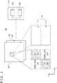
- FIG. 1 is a diagram illustrating a schematic configuration of a system according to a first embodiment of the present invention.
- a system 10 includes a vision sensor 100 and an information processing device 200.
- the vision sensor 100 which is of an event-driven type, includes a sensor array 120 where sensors 110 are arranged.
- the sensors 110 generate event signals when detecting a change in an intensity of light incident through an undepicted optical system, or more specifically, when detecting a luminance change in the light. If a sensor 110 detects no intensity change in the light, this sensor 110 does not generate an event signal. Therefore, the vision sensor 100 asynchronously generates the event signals.
- the event signals outputted from the vision sensor 100 include sensor identification information (e.g., the position of a pixel), the polarity of luminance change (luminance increase or decrease), and a timestamp.
- a filter 300 corresponding to the vision sensor 100 is disposed.
- the filter 300 includes first filters 310 and second filters 320.
- the first filters 310 selectively pass light in a first wavelength band.
- the second filters 320 selectively pass light in a second wavelength band that is different from the first wavelength band.
- the first filters 310 and the second filters 320 are alternately arranged in two directions on a plane (depicted as an x-direction and a ⁇ -direction orthogonal to each other).
- the filter 300 is disposed such that the first filters 310 and the second filters 320 respectively correspond to one or more sensors 110 in the vision sensor 100.
- the sensors 110 include first sensors 111 on which light is incident through the first filters 310, and second sensors 112 on which light is incident through the second filters 320.
- the first sensors 111 and the second sensors 112 are arranged in a predetermined pattern in the sensor array 120, or more specifically, arranged in the same pattern as that of the first filters 310 and the second filters 320 included in the filter 300.
- First event signals generated by the first sensors 111 and second event signals generated by the second sensors 112 can be distinguished from each other by the sensor identification information included in the event signals.
- the information processing device 200 includes, as functional parts, a first processing section 210 and a second processing section 220.
- the first processing section 210 and the second processing section 220 are implemented by a computer having, for example, a communication interface, a processor, and a memory, and realized by allowing the processor to operate according to a program stored in the memory or received through the communication interface.
- the first processing section 210 executes a first process on the basis of the first event signals generated by the first sensors 111 in the vision sensor 100.
- the second processing section 220 executes a second process on the basis of the second event signals generated by the second sensors 112 in the vision sensor 100. The second process is different from the second process.
- the information processing device 200 may be, for example, incorporated in the same hardware as the vision sensor 100, may be a terminal device disposed in the same space as the vision sensor 100 to communicate with the vision sensor 100, or may be a server device connected to the vision sensor 100 through a network.
- An alternative is to allow the terminal device to implement some functions of the information processing device 200 and allow the server device to implement the other functions.
- the above-described system 10 can be used for a process of estimating the own position of the game controller on the basis of an event detected by the vision sensor 100.
- the first filters 310 included in the filter 300 selectively pass the light in the visible light region
- the second filters 320 selectively pass the light in the infrared light region.
- the first processing section 210 executes a position/posture calculation process by using surrounding environment information, on the basis of the first event signals that the first sensors 111 generate when detecting visible light events.
- the second processing section 220 corrects the position and the posture calculated by processing performed by the first processing section 210, on the basis of the second event signals that the second sensors 112 generate when detecting infrared light events emitted by IR (infrared) markers disposed around the game controller. This correction reduces drift errors that occur in a case where only the position/posture calculation process using the surrounding environment information is executed.
- FIG. 2 is a flowchart illustrating an example of processing in the first embodiment of the present invention.
- event signals received by the information processing device 200 (step S101) are the first event signals generated by the first sensors 111 included in the vision sensor 100 ("YES" in step S102)
- the first processing section 210 executes the first process (step S103).
- the second processing section 220 performs the second process (step S104).
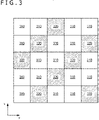
- FIG. 3 is a diagram illustrating an alternative example of a filter and sensor arrangement pattern in the first embodiment of the present invention.
- the first filters 310 and the second filters 320 are unevenly arranged in the filter 300. More specifically, although the first filters 310 and the second filters 320 are alternately arranged in two directions on a plane (depicted as the x-direction and the ⁇ -direction orthogonal to each other), the ratio between the first filters 310 and the second filters 320 is 2:1 in each direction. In the sensors 110, too, the first and second sensors 111 and 112 are similarly arranged in an uneven pattern.
- the infrared light event is surely detected even if the second filters 320 are spaced apart from each other in the arrangement pattern depicted in the example of the FIG. 3 .
- arranging the filters and the sensors in the above-described uneven pattern makes it possible to relatively enlarge the region of the first filters 310 and thus increase the resolution of the visible light event.
- FIG. 4 is a diagram illustrating a schematic configuration of a system according to a second embodiment of the present invention.
- a system 20 includes the vision sensor 100, which is of the event-driven type, and an information processing device 400.
- the vision sensor 100 has the same configuration as in the first embodiment.
- a filter 500 disposed in correspondence with the vision sensor 100 includes first to fourth filters 510 to 540, which selectively pass light in four different respective wavelength bands.
- the first to fourth filters 510 to 540 are arranged in such a pattern that they are alternately disposed in two directions on a plane (depicted as the x-direction and the ⁇ -direction orthogonal to each other) in correspondence with the one or more sensors 110 of the vision sensor 100, respectively.
- the sensor 110 are divided into first to fourth sensors 111 to 114 on which light is incident respectively through the first to fourth filters 510 to 540.
- the first to fourth sensors 111 to 114 are arranged in a predetermined pattern in the sensor array 120, or more specifically, arranged in the same pattern as that of the first to fourth filters 510 to 540 included in the filter 500.
- first to fourth event signals respectively generated by the first to fourth sensors 111 to 114 can be distinguished from one another by the sensor identification information included in the event signals.
- the information processing device 400 includes, as functional parts, first to eighth processing sections 410 to 480.
- the first to eighth processing sections 410 to 480 are implemented by a computer having, for example, a communication interface, a processor, and a memory, and realized by allowing the processor to operate according to a program stored in the memory or received through the communication interface.
- the first to fourth processing sections 410 to 440 in the information processing device 400 execute first to fourth processes, which are different from one another, on the basis of the first to fourth event signals respectively generated by the first to fourth sensors 111 to 114 in the vision sensor 100, as is the case with the first and second processing sections 210 and 220 in the first embodiment described earlier.
- the fifth to eighth processing sections 450 to 480 in the information processing device 400 execute fifth to eighth processes, which are different from one another (also different from the first to fourth processes mentioned above), on the basis of event signals that are generated simultaneously or successively at predetermined or shorter time intervals by two or more of the first to fourth sensors 111 to 114 in the vision sensor 100.
- the event signals are generated by the sensors on which light is incident through the filters that selectively pass light in the respective wavelength bands.
- the fifth to eighth processing sections 450 to 480 execute the predetermined processes on the basis of the event signals that are generated simultaneously or at the predetermined or shorter time intervals by two or more different sensors adjacent or close to each other in the arrangement pattern of the first to fourth sensors 111 to 114.
- the above-described system 20 can be used for a process of tracking markers that are configured to emit light having different wavelengths and are attached to a plurality of objects moving in the angle of view of the vision sensor 100.
- the system 20 is able to identify and track the markers that emit light having eight different wavelengths in a predetermined blinking pattern as depicted in FIG. 5 .
- the wavelength band of light remains unchanged as described in conjunction with the present embodiment, it is necessary to vary the marker's blinking pattern as depicted in FIG. 6 in order to identify the markers with use of the event signals.
- the cycle of the blinking pattern becomes longer with an increase in the number of types of markers to be identified. This increases latency despite the use of an event-driven vision sensor that operates at a high speed.
- An example of the present embodiment makes it possible to identify, for example, eight different markers while maintaining latency by applying the same blinking pattern to the markers as depicted in FIG. 5 .
- the first to eighth processing sections 410 to 480 of the information processing device 400 execute a process of tracking different types of markers, respectively.
- FIG. 7 is a diagram illustrating an alternative example of a filter and sensor arrangement pattern in the second embodiment of the present invention.
- the first to fourth filters 510 to 540 included in the filter 500 are arranged alternately in two directions on a plane (depicted as the x-direction and the ⁇ -direction orthogonal to each other).
- the first to fourth filters 510 to 540 are arranged alternately only in the x-direction.
- the first to fourth filters 510 to 540 are arranged in a striped pattern in the ⁇ -direction.
- the first to fourth sensors 111 to 114 are arranged in a similar striped pattern.
- an event occurring in a region less than four times as large as the filter size may be blocked in the x-direction by a filter passing light in a different wavelength band.
- such blocking does not occur in the ⁇ -direction.
- an event occurring in a region two or more times as large as the filter size is detected in both the x-direction and the ⁇ -direction without being blocked.
- the filter and sensor arrangement pattern can be changed as needed depending, for example, on the size of an event to be detected in respective directions.
- FIG. 8 is a diagram illustrating a schematic configuration of a system according to a third embodiment of the present invention.
- a system 30 includes a vision sensor 600, which is of an event-driven type, and an information processing device 700.
- the filter 500 disposed in correspondence with the vision sensor 600 has a configuration similar to that of the second embodiment described earlier.
- the sensors arranged in a sensor array 620 of the vision sensor 600 include sensors 610A and sensors 610B.
- the sensors 610A are in a first subgroup whose light intensity change detection threshold value is set to a first threshold value.
- the sensors 610B are in a second subgroup whose light intensity change detection threshold value is set to a second threshold value that is smaller than the first threshold value.
- the sensors 610A in the first subgroup and the sensors 610B in the second subgroup are disposed so as to respectively include first to fourth sensors 611A to 614A and 611B to 614B. Beams of light transmitted through the first to fourth filters 510 to 540 are respectively incident on the first to fourth sensors 611A to 614A and 611B to 614B.
- the first sensors 611A and 611B include the sensor 611A in the first subgroup and the sensor 611B in the second subgroup. The same is true for the second to fourth sensors.
- the information processing device 700 includes, as functional parts, 16 processing sections 710-1, 710-2, ..., 710-16.
- the processing sections 710-1, 710-2, ..., 710-16 are implemented by a computer having, for example, a communication interface, a processor, and a memory, and realized by allowing the processor to operate according to a program stored in the memory or received through the communication interface.
- the processing section 710-1 which is one of the functional parts, executes a predetermined process when event signals are generated by both the sensor 611A in the first subgroup and the sensor 611B in the second subgroup, which are included in the vision sensor 600.
- the processing section 710-2 executes a process different from the process executed by the processing section 710-1 when an event signal is generated by the sensor 611B in the second subgroup although no event signal is generated by the sensor 611A in the first subgroup.
- the first processing section (the first processing section 410 in the second embodiment), which executes the first process on the basis of the first event signals generated by the first sensors 611A and 611B, executes two different subprocesses, according to the above-mentioned type of event signal generation by the sensors 611A and 611B in the individual subgroups.
- the same is true for the relation between the processing sections 710-3 to 710-16 and the second to eighth processing sections 420 to 480 in the second embodiment.
- subprocesses is merely used to compare with the processes executed, for example, by the first processing section in the first and second embodiments.
- the details of the subprocesses may be the same as those of the processes executed, for example, by the first processing section in the first and second embodiments.
- the above-described system 30 can be used for a process of tracking markers that are attached to a plurality of objects moving in the angle of view of the vision sensor 600, as is the case with the second embodiment described earlier.
- the system 30 is able to identify and track 16 different markers that emit light having eight different wavelengths in two blinking patterns differing in light intensity, as depicted in FIG. 9 .
- the two different blinking patterns include a first pattern and a second pattern.
- the first pattern blinks at a light intensity not lower than a detection threshold value of the sensor 610A in the first subgroup.
- the second pattern blinks at a light intensity lower than the detection threshold value of the sensor 610A in the first subgroup and not lower than the detection threshold value of the sensor 610B in the second subgroup.
- An example of the present embodiment makes it possible to identify more different markers while maintaining latency by applying the same blinking pattern to the markers, as is the case with the second embodiment.
- the processing sections 710-1 to 710-16 of the information processing device 700 execute a process of tracking different types of markers, respectively.
- an alternative may be to set three or more different blinking intensities for the markers, define three or more sensor subgroups having threshold values corresponding to the respective blinking intensities, and thus execute a larger number of different processes, or more specifically, track different types of markers.
- an information processing device executes processing based on event signals generated by event-driven vision sensors corresponding to filters that are disposed to selectively pass light in a predetermined wavelength band in correspondence with the event-driven vision sensors, it is possible to execute different processes depending on the wavelength band of light in which an intensity change has occurred.
- the resolution of event detection decreases with an increase in the number of types of filters, such a resolution decrease can be compensated for by publicly-known technologies such as interpolation and extrapolation.
- the uneven arrangement pattern of filters and sensors in the first embodiment which is described with reference to FIG. 3
- the striped arrangement pattern of filters and sensors in the second embodiment which is described with reference to FIG. 7
- the sensor 610A in the first subgroup and the sensor 610B in the second subgroup may be arranged in a striped pattern in the x-direction or the ⁇ -direction instead of being each alternately arranged in the x-direction and the ⁇ -direction.
- the embodiments of the present invention can be used in a situation where, for example, game controllers, smartphones, and various moving vehicles (e.g., automobiles, electric vehicles, hybrid electric vehicles, motorcycles, bicycles, personal mobilities, airplanes, drones, and robots) acquire information regarding a surrounding environment, estimate the own position from the position of a peripheral object, or detect a flying object and take evasive action.
- various moving vehicles e.g., automobiles, electric vehicles, hybrid electric vehicles, motorcycles, bicycles, personal mobilities, airplanes, drones, and robots
Landscapes
- Engineering & Computer Science (AREA)
- Signal Processing (AREA)
- Multimedia (AREA)
- Physics & Mathematics (AREA)
- Spectroscopy & Molecular Physics (AREA)
- General Physics & Mathematics (AREA)
- Optics & Photonics (AREA)
- Health & Medical Sciences (AREA)
- Toxicology (AREA)
- Length Measuring Devices By Optical Means (AREA)
- Transforming Light Signals Into Electric Signals (AREA)
- Color Television Image Signal Generators (AREA)
- Studio Devices (AREA)
- Photometry And Measurement Of Optical Pulse Characteristics (AREA)
Abstract
Description
- The present invention relates to a system, an information processing device, an information processing method, and a program.
- There is known an event-driven vision sensor that allows pixels to detect a change in an intensity of incident light and to asynchronously generate a signal. The event-driven vision sensor is advantageous in being operable at a high speed with low power consumption compared to a frame-based vision sensor configured to scan all pixels at each predetermined cycle, or more specifically, an image sensor such as a CCD (Charge Coupled Device) image sensor or a CMOS (Complementary Metal Oxide Semiconductor) image sensor. Technologies related to such event-driven vision sensors are described, for example, in
PTL 1 andPTL 2. -
- [PTL 1]
Japanese Translation of PCT for Patent No. 2014-535098 - [PTL 2]
Japanese Patent Laid-open No. 2018-85725 - However, although the above-mentioned advantage of event-driven vision sensors is known, it can hardly be said that peripheral technologies based on characteristics different from those of conventional vision sensors, such as frame-based vision sensors, are adequately proposed.
- In view of the above circumstances, an object of the present invention is to provide a system, an information processing device, an information processing method, and a program that, when processing is to be executed based on an event signal generated when a change in the intensity of light is detected by an event-driven vision sensor, make it possible to execute different processes depending on a wavelength band of light in which the intensity change has occurred.
- According to an aspect of the present invention, there is provided a system including an event-driven vision sensor that includes a sensor array where a first sensor and a second sensor are arranged in a predetermined pattern, the first sensor generating a first event signal when detecting a change in an intensity of light incident through a first filter, the first filter selectively passing light in a first wavelength band, the second sensor generating a second event signal when detecting a change in an intensity of light incident through a second filter, the second filter selectively passing light in a second wavelength band that is different from the first wavelength band, and an information processing device that includes a first processing section and a second processing section, the first processing section executing a first process on the basis of the first event signal, the second processing section executing a second process different from the first process on the basis of the second event signal.
- According to another aspect of the present invention, there is provided an information processing device including a first processing section that executes a first process, on the basis of a first event signal that a first sensor generates when detecting a change in an intensity of light incident through a first filter, the first sensor being arranged in a predetermined pattern in a sensor array of an event-driven vision sensor, the first filter selectively passing light in a first wavelength band, and a second processing section that executes a second process, on the basis of a second event signal that a second sensor generates when detecting a change in an intensity of light incident through a second filter, the second process being different from the first process, the second sensor being arranged together with the first sensor in the predetermined pattern in the sensor array, the second filter selectively passing light in a second wavelength band that is different from the first wavelength band.
- According to yet another aspect of the present invention, there is provided an information processing method including the steps of executing a first process, on the basis of a first event signal that a first sensor generates when detecting a change in an intensity of light incident through a first filter, the first sensor being arranged in a predetermined pattern in a sensor array of an event-driven vision sensor, the first filter selectively passing light in a first wavelength band, and executing a second process, on the basis of a second event signal that a second sensor generates when detecting a change in an intensity of light incident through a second filter, the second process being different from the first process, the second sensor being arranged together with the first sensor in the predetermined pattern in the sensor array, the second filter selectively passing light in a second wavelength band that is different from the first wavelength band.
- According to still another aspect of the present invention, there is provided a program for causing a computer to function as an information processing device that includes a first processing section that executes a first process, on the basis of a first event signal that a first sensor generates when detecting a change in an intensity of light incident through a first filter, the first sensor being arranged in a predetermined pattern in a sensor array of an event-driven vision sensor, the first filter selectively passing light in a first wavelength band, and a second processing section that executes a second process, on the basis of a second event signal that a second sensor generates when detecting a change in an intensity of light incident through a second filter, the second process being different from the first process, the second sensor being arranged together with the first sensor in the predetermined pattern in the sensor array, the second filter selectively passing light in a second wavelength band that is different from the first wavelength band.
- According to the above-described configurations, when processing is to be executed based on an event signal generated when a change in the intensity of light is detected by an event-driven vision sensor, it is possible to execute different processes depending on the wavelength band of light in which the intensity change has occurred.
-
- [
FIG. 1 ]
FIG. 1 is a diagram illustrating a schematic configuration of a system according to a first embodiment of the present invention. - [
FIG. 2 ]
FIG. 2 is a flowchart illustrating an example of processing in the first embodiment of the present invention. - [
FIG. 3 ]
FIG. 3 is a diagram illustrating an alternative example of a filter and sensor arrangement pattern in the first embodiment of the present invention. - [
FIG. 4 ]
FIG. 4 is a diagram illustrating a schematic configuration of a system according to a second embodiment of the present invention. - [
FIG. 5 ]
FIG. 5 is a diagram illustrating an example of a marker's blinking pattern in a specific example of the second embodiment. - [
FIG. 6 ]
FIG. 6 is a diagram illustrating the marker's blinking pattern in a case where the wavelength band of light remains unchanged. - [
FIG. 7 ]
FIG. 7 is a diagram illustrating an alternative example of a filter and sensor arrangement pattern in the second embodiment of the present invention. - [
FIG. 8 ]
FIG. 8 is a diagram illustrating a schematic configuration of a system according to a third embodiment of the present invention. - [
FIG. 9 ]
FIG. 9 is a diagram illustrating an example of a marker's blinking pattern in a specific example of the third embodiment. - Preferred embodiments of the present invention will now be described in detail with reference to the accompanying drawings. In this document and the accompanying drawings, components having substantially identical functional configurations are designated by the same reference signs and will not be redundantly described.
-
FIG. 1 is a diagram illustrating a schematic configuration of a system according to a first embodiment of the present invention. In an example depicted inFIG. 1 , asystem 10 includes avision sensor 100 and aninformation processing device 200. Thevision sensor 100, which is of an event-driven type, includes asensor array 120 wheresensors 110 are arranged. Thesensors 110 generate event signals when detecting a change in an intensity of light incident through an undepicted optical system, or more specifically, when detecting a luminance change in the light. If asensor 110 detects no intensity change in the light, thissensor 110 does not generate an event signal. Therefore, thevision sensor 100 asynchronously generates the event signals. The event signals outputted from thevision sensor 100 include sensor identification information (e.g., the position of a pixel), the polarity of luminance change (luminance increase or decrease), and a timestamp. - In the present embodiment, a
filter 300 corresponding to thevision sensor 100 is disposed. Thefilter 300 includesfirst filters 310 andsecond filters 320. Thefirst filters 310 selectively pass light in a first wavelength band. Thesecond filters 320 selectively pass light in a second wavelength band that is different from the first wavelength band. Thefirst filters 310 and thesecond filters 320 are alternately arranged in two directions on a plane (depicted as an x-direction and a γ-direction orthogonal to each other). Thefilter 300 is disposed such that thefirst filters 310 and thesecond filters 320 respectively correspond to one ormore sensors 110 in thevision sensor 100. - Consequently, in the present embodiment, the
sensors 110 includefirst sensors 111 on which light is incident through thefirst filters 310, andsecond sensors 112 on which light is incident through thesecond filters 320. Thefirst sensors 111 and thesecond sensors 112 are arranged in a predetermined pattern in thesensor array 120, or more specifically, arranged in the same pattern as that of thefirst filters 310 and thesecond filters 320 included in thefilter 300. First event signals generated by thefirst sensors 111 and second event signals generated by thesecond sensors 112 can be distinguished from each other by the sensor identification information included in the event signals. - The
information processing device 200 includes, as functional parts, afirst processing section 210 and asecond processing section 220. Thefirst processing section 210 and thesecond processing section 220 are implemented by a computer having, for example, a communication interface, a processor, and a memory, and realized by allowing the processor to operate according to a program stored in the memory or received through the communication interface. Thefirst processing section 210 executes a first process on the basis of the first event signals generated by thefirst sensors 111 in thevision sensor 100. Meanwhile, thesecond processing section 220 executes a second process on the basis of the second event signals generated by thesecond sensors 112 in thevision sensor 100. The second process is different from the second process. More specifically, in a case where a light intensity change (event) has occurred only in the first wavelength band at a position in the angle of view of thevision sensor 100, only thefirst sensors 111 generate the first event signals to let only thefirst processing section 210 execute processing. Meanwhile, in a case where the event has occurred only in the second wavelength band at another position in the angle of view of thevision sensor 100, only thesecond sensors 112 generate the second event signals to let only thesecond processing section 220 execute processing. - Further, the
information processing device 200 may be, for example, incorporated in the same hardware as thevision sensor 100, may be a terminal device disposed in the same space as thevision sensor 100 to communicate with thevision sensor 100, or may be a server device connected to thevision sensor 100 through a network. An alternative is to allow the terminal device to implement some functions of theinformation processing device 200 and allow the server device to implement the other functions. - When, for example, the
vision sensor 100 and thefilter 300 are incorporated in a game controller, the above-describedsystem 10 can be used for a process of estimating the own position of the game controller on the basis of an event detected by thevision sensor 100. In this case, thefirst filters 310 included in thefilter 300 selectively pass the light in the visible light region, and thesecond filters 320 selectively pass the light in the infrared light region. In theinformation processing device 200, thefirst processing section 210 executes a position/posture calculation process by using surrounding environment information, on the basis of the first event signals that thefirst sensors 111 generate when detecting visible light events. Meanwhile, thesecond processing section 220 corrects the position and the posture calculated by processing performed by thefirst processing section 210, on the basis of the second event signals that thesecond sensors 112 generate when detecting infrared light events emitted by IR (infrared) markers disposed around the game controller. This correction reduces drift errors that occur in a case where only the position/posture calculation process using the surrounding environment information is executed. -
FIG. 2 is a flowchart illustrating an example of processing in the first embodiment of the present invention. In the example depicted inFIG. 2 , in a case where event signals received by the information processing device 200 (step S101) are the first event signals generated by thefirst sensors 111 included in the vision sensor 100 ("YES" in step S102), thefirst processing section 210 executes the first process (step S103). Meanwhile, in a case where the received event signals are not the first event signals, but are the second event signals generated by thesecond sensors 112 included in the vision sensor 100 ("NO" in step S102), thesecond processing section 220 performs the second process (step S104). -
FIG. 3 is a diagram illustrating an alternative example of a filter and sensor arrangement pattern in the first embodiment of the present invention. In the example depicted inFIG. 3 , thefirst filters 310 and thesecond filters 320 are unevenly arranged in thefilter 300. More specifically, although thefirst filters 310 and thesecond filters 320 are alternately arranged in two directions on a plane (depicted as the x-direction and the γ-direction orthogonal to each other), the ratio between thefirst filters 310 and thesecond filters 320 is 2:1 in each direction. In thesensors 110, too, the first andsecond sensors second filters 320 are spaced apart from each other in the arrangement pattern depicted in the example of theFIG. 3 . In this case, arranging the filters and the sensors in the above-described uneven pattern makes it possible to relatively enlarge the region of thefirst filters 310 and thus increase the resolution of the visible light event. -
FIG. 4 is a diagram illustrating a schematic configuration of a system according to a second embodiment of the present invention. In an example depicted inFIG. 4 , asystem 20 includes thevision sensor 100, which is of the event-driven type, and aninformation processing device 400. In the present embodiment, thevision sensor 100 has the same configuration as in the first embodiment. However, afilter 500 disposed in correspondence with thevision sensor 100 includes first tofourth filters 510 to 540, which selectively pass light in four different respective wavelength bands. The first tofourth filters 510 to 540 are arranged in such a pattern that they are alternately disposed in two directions on a plane (depicted as the x-direction and the γ-direction orthogonal to each other) in correspondence with the one ormore sensors 110 of thevision sensor 100, respectively. - Consequently, in the present embodiment, the
sensor 110 are divided into first tofourth sensors 111 to 114 on which light is incident respectively through the first tofourth filters 510 to 540. The first tofourth sensors 111 to 114 are arranged in a predetermined pattern in thesensor array 120, or more specifically, arranged in the same pattern as that of the first tofourth filters 510 to 540 included in thefilter 500. As is the case with the first embodiment described above, first to fourth event signals respectively generated by the first tofourth sensors 111 to 114 can be distinguished from one another by the sensor identification information included in the event signals. - The
information processing device 400 includes, as functional parts, first toeighth processing sections 410 to 480. The first toeighth processing sections 410 to 480 are implemented by a computer having, for example, a communication interface, a processor, and a memory, and realized by allowing the processor to operate according to a program stored in the memory or received through the communication interface. Of the first toeighth processing sections 410 to 480, the first tofourth processing sections 410 to 440 in theinformation processing device 400 execute first to fourth processes, which are different from one another, on the basis of the first to fourth event signals respectively generated by the first tofourth sensors 111 to 114 in thevision sensor 100, as is the case with the first andsecond processing sections - Meanwhile, the fifth to
eighth processing sections 450 to 480 in theinformation processing device 400 execute fifth to eighth processes, which are different from one another (also different from the first to fourth processes mentioned above), on the basis of event signals that are generated simultaneously or successively at predetermined or shorter time intervals by two or more of the first tofourth sensors 111 to 114 in thevision sensor 100. For example, in a case where a change has occurred in the intensity of light in two wavelength bands at a position in the angle of view of thevision sensor 100, the event signals are generated by the sensors on which light is incident through the filters that selectively pass light in the respective wavelength bands. Therefore, the fifth toeighth processing sections 450 to 480 execute the predetermined processes on the basis of the event signals that are generated simultaneously or at the predetermined or shorter time intervals by two or more different sensors adjacent or close to each other in the arrangement pattern of the first tofourth sensors 111 to 114. - The above-described
system 20 can be used for a process of tracking markers that are configured to emit light having different wavelengths and are attached to a plurality of objects moving in the angle of view of thevision sensor 100. For example, in a case where the first tofourth filters 510 to 540 selectively pass light in the green, blue, red, and infrared light regions, respectively, thesystem 20 is able to identify and track the markers that emit light having eight different wavelengths in a predetermined blinking pattern as depicted inFIG. 5 . In a case, for example, where the wavelength band of light remains unchanged as described in conjunction with the present embodiment, it is necessary to vary the marker's blinking pattern as depicted inFIG. 6 in order to identify the markers with use of the event signals. In this case, however, the cycle of the blinking pattern becomes longer with an increase in the number of types of markers to be identified. This increases latency despite the use of an event-driven vision sensor that operates at a high speed. An example of the present embodiment makes it possible to identify, for example, eight different markers while maintaining latency by applying the same blinking pattern to the markers as depicted inFIG. 5 . In this case, the first toeighth processing sections 410 to 480 of theinformation processing device 400 execute a process of tracking different types of markers, respectively. -
FIG. 7 is a diagram illustrating an alternative example of a filter and sensor arrangement pattern in the second embodiment of the present invention. In the above-described example depicted inFIG. 4 , the first tofourth filters 510 to 540 included in thefilter 500 are arranged alternately in two directions on a plane (depicted as the x-direction and the γ-direction orthogonal to each other). In the example depicted inFIG. 7 , however, the first tofourth filters 510 to 540 are arranged alternately only in the x-direction. In other words, the first tofourth filters 510 to 540 are arranged in a striped pattern in the γ-direction. In thesensors 110, too, the first tofourth sensors 111 to 114 are arranged in a similar striped pattern. In this case, an event occurring in a region less than four times as large as the filter size may be blocked in the x-direction by a filter passing light in a different wavelength band. However, such blocking does not occur in the γ-direction. Meanwhile, in the above-described example depicted inFIG. 4 , an event occurring in a region two or more times as large as the filter size is detected in both the x-direction and the γ-direction without being blocked. As described above, the filter and sensor arrangement pattern can be changed as needed depending, for example, on the size of an event to be detected in respective directions. -
FIG. 8 is a diagram illustrating a schematic configuration of a system according to a third embodiment of the present invention. In an example depicted inFIG. 8 , asystem 30 includes avision sensor 600, which is of an event-driven type, and aninformation processing device 700. In the present embodiment, thefilter 500 disposed in correspondence with thevision sensor 600 has a configuration similar to that of the second embodiment described earlier. However, the sensors arranged in asensor array 620 of thevision sensor 600 includesensors 610A andsensors 610B. Thesensors 610A are in a first subgroup whose light intensity change detection threshold value is set to a first threshold value. Thesensors 610B are in a second subgroup whose light intensity change detection threshold value is set to a second threshold value that is smaller than the first threshold value. Thesensors 610A in the first subgroup and thesensors 610B in the second subgroup are disposed so as to respectively include first tofourth sensors 611A to 614A and 611B to 614B. Beams of light transmitted through the first tofourth filters 510 to 540 are respectively incident on the first tofourth sensors 611A to 614A and 611B to 614B. In other words, in the present embodiment, thefirst sensors sensor 611A in the first subgroup and thesensor 611B in the second subgroup. The same is true for the second to fourth sensors. - The
information processing device 700 includes, as functional parts, 16 processing sections 710-1, 710-2, ..., 710-16. The processing sections 710-1, 710-2, ..., 710-16 are implemented by a computer having, for example, a communication interface, a processor, and a memory, and realized by allowing the processor to operate according to a program stored in the memory or received through the communication interface. The processing section 710-1, which is one of the functional parts, executes a predetermined process when event signals are generated by both thesensor 611A in the first subgroup and thesensor 611B in the second subgroup, which are included in thevision sensor 600. The processing section 710-2 executes a process different from the process executed by the processing section 710-1 when an event signal is generated by thesensor 611B in the second subgroup although no event signal is generated by thesensor 611A in the first subgroup. Stated differently, in the present embodiment, the first processing section (thefirst processing section 410 in the second embodiment), which executes the first process on the basis of the first event signals generated by thefirst sensors sensors eighth processing sections 420 to 480 in the second embodiment. It should be noted that the term "subprocesses" is merely used to compare with the processes executed, for example, by the first processing section in the first and second embodiments. The details of the subprocesses may be the same as those of the processes executed, for example, by the first processing section in the first and second embodiments. - The above-described
system 30 can be used for a process of tracking markers that are attached to a plurality of objects moving in the angle of view of thevision sensor 600, as is the case with the second embodiment described earlier. For example, thesystem 30 is able to identify and track 16 different markers that emit light having eight different wavelengths in two blinking patterns differing in light intensity, as depicted inFIG. 9 . The two different blinking patterns include a first pattern and a second pattern. The first pattern blinks at a light intensity not lower than a detection threshold value of thesensor 610A in the first subgroup. The second pattern blinks at a light intensity lower than the detection threshold value of thesensor 610A in the first subgroup and not lower than the detection threshold value of thesensor 610B in the second subgroup. An example of the present embodiment makes it possible to identify more different markers while maintaining latency by applying the same blinking pattern to the markers, as is the case with the second embodiment. In this case, the processing sections 710-1 to 710-16 of theinformation processing device 700 execute a process of tracking different types of markers, respectively. For example, an alternative may be to set three or more different blinking intensities for the markers, define three or more sensor subgroups having threshold values corresponding to the respective blinking intensities, and thus execute a larger number of different processes, or more specifically, track different types of markers. - According to the foregoing embodiments of the present invention, when an information processing device executes processing based on event signals generated by event-driven vision sensors corresponding to filters that are disposed to selectively pass light in a predetermined wavelength band in correspondence with the event-driven vision sensors, it is possible to execute different processes depending on the wavelength band of light in which an intensity change has occurred. Although the resolution of event detection decreases with an increase in the number of types of filters, such a resolution decrease can be compensated for by publicly-known technologies such as interpolation and extrapolation.
- It should be noted that modifications described in conjunction with one of the foregoing embodiments are also applicable to another one of the foregoing embodiments. For example, the uneven arrangement pattern of filters and sensors in the first embodiment, which is described with reference to
FIG. 3 , is also applicable to the second and third embodiments. Further, the striped arrangement pattern of filters and sensors in the second embodiment, which is described with reference toFIG. 7 , is also applicable to the first and third embodiments. In the third embodiment, thesensor 610A in the first subgroup and thesensor 610B in the second subgroup may be arranged in a striped pattern in the x-direction or the γ-direction instead of being each alternately arranged in the x-direction and the γ-direction. - The embodiments of the present invention can be used in a situation where, for example, game controllers, smartphones, and various moving vehicles (e.g., automobiles, electric vehicles, hybrid electric vehicles, motorcycles, bicycles, personal mobilities, airplanes, drones, and robots) acquire information regarding a surrounding environment, estimate the own position from the position of a peripheral object, or detect a flying object and take evasive action.
- While the preferred embodiments of the present invention have been described in detail with reference to the accompanying drawings, the present invention is not limited to such preferred embodiments. It should be understood that various modifications and corrections will become apparent to persons of ordinary skill in the art, and that such modifications and corrections are intended to be obviously included within the technical scope described in claims.
-
- 10, 20, 30: System
- 100, 600: Event-driven vision sensor
- 110: Sensor
- 120: Sensor array
- 200, 400, 700: Information processing device
- 210: First processing section
- 220: Second processing section
- 300, 500: Filter
Claims (10)
- A system comprising:an event-driven vision sensor that includes a sensor array where a first sensor and a second sensor are arranged in a predetermined pattern, the first sensor generating a first event signal when detecting a change in an intensity of light incident through a first filter, the first filter selectively passing light in a first wavelength band, the second sensor generating a second event signal when detecting a change in an intensity of light incident through a second filter, the second filter selectively passing light in a second wavelength band that is different from the first wavelength band; andan information processing device that includes a first processing section and a second processing section, the first processing section executing a first process on a basis of the first event signal, the second processing section executing a second process different from the first process on a basis of the second event signal.
- The system according to claim 1,wherein the first filter selectively passes light in a visible light region, andthe second filter selectively passes light in an infrared light region.
- The system according to claim 1 or 2,wherein the sensor array is configured such that a third sensor is arranged in the predetermined pattern together with the first sensor and the second sensor, the third sensor generating a third event signal when detecting a change in an intensity of light incident through a third filter, the third filter selectively passing light in a third wavelength band that is different from the first wavelength band and the second wavelength band, andthe information processing device further includes a third processing section that executes a third process on a basis of the third event signal.
- The system according to any one of claims 1 to 3, wherein the information processing device further includes a fourth processing section, the fourth processing section executing a fourth process on a basis of the first event signal and the second event signal that are generated simultaneously or successively at predetermined or shorter time intervals by the first sensor and the second sensor adjacent or close to each other in the predetermined pattern.
- The system according to any one of claims 1 to 4,wherein at least the first sensor includes a sensor in a first subgroup and a sensor in a second subgroup, the first subgroup having a first threshold value as a light intensity change detection threshold value, the second subgroup having a second threshold value as the light intensity change detection threshold value, the second threshold value being smaller than the first threshold value, andat least the first processing section executes a first subprocess when the first event signals are generated by both the sensor in the first subgroup and the sensor in the second subgroup, and executes a second subprocess different from the first subprocess when the first event signal is generated by the sensor in the second subgroup and not by the sensor in the first subgroup.
- The system according to any one of claims 1 to 5,
wherein the sensor array is configured such that the first sensor and the second sensor are each arranged in a first direction and a second direction, the second direction being orthogonal to the first direction, and the predetermined pattern is configured such that the first sensor and the second sensor are each alternately arranged in the first direction and the second direction. - The system according to any one of claims 1 to 5,
wherein the sensor array is configured such that the first sensor and the second sensor are each arranged in a first direction and a second direction, the second direction being orthogonal to the first direction, and the predetermined pattern is configured such that the first sensor and the second sensor are arranged alternately only in the first direction. - An information processing device comprising:a first processing section that executes a first process, on a basis of a first event signal that a first sensor generates when detecting a change in an intensity of light incident through a first filter, the first sensor being arranged in a predetermined pattern in a sensor array of an event-driven vision sensor, the first filter selectively passing light in a first wavelength band; anda second processing section that executes a second process, on a basis of a second event signal that a second sensor generates when detecting a change in an intensity of light incident through a second filter, the second process being different from the first process, the second sensor being arranged together with the first sensor in the predetermined pattern in the sensor array, the second filter selectively passing light in a second wavelength band that is different from the first wavelength band.
- An information processing method comprising the steps of:executing a first process, on a basis of a first event signal that a first sensor generates when detecting a change in an intensity of light incident through a first filter, the first sensor being arranged in a predetermined pattern in a sensor array of an event-driven vision sensor, the first filter selectively passing light in a first wavelength band; andexecuting a second process, on a basis of a second event signal that a second sensor generates when detecting a change in an intensity of light incident through a second filter, the second process being different from the first process, the second sensor being arranged together with the first sensor in the predetermined pattern in the sensor array, the second filter selectively passing light in a second wavelength band that is different from the first wavelength band.
- A program for causing a computer to function as an information processing device, the information processing device comprising:a first processing section that executes a first process, on a basis of a first event signal that a first sensor generates when detecting a change in an intensity of light incident through a first filter, the first sensor being arranged in a predetermined pattern in a sensor array of an event-driven vision sensor, the first filter selectively passing light in a first wavelength band; anda second processing section that executes a second process, on a basis of a second event signal that a second sensor generates when detecting a change in an intensity of light incident through a second filter, the second process being different from the first process, the second sensor being arranged together with the first sensor in the predetermined pattern in the sensor array, the second filter selectively passing light in a second wavelength band that is different from the first wavelength band.
Applications Claiming Priority (1)
| Application Number | Priority Date | Filing Date | Title |
|---|---|---|---|
| PCT/JP2019/025306 WO2020261408A1 (en) | 2019-06-26 | 2019-06-26 | System, information processing device, information processing method, and program |
Publications (3)
| Publication Number | Publication Date |
|---|---|
| EP3993398A1 true EP3993398A1 (en) | 2022-05-04 |
| EP3993398A4 EP3993398A4 (en) | 2023-01-25 |
| EP3993398B1 EP3993398B1 (en) | 2025-11-12 |
Family
ID=74060840
Family Applications (1)
| Application Number | Title | Priority Date | Filing Date |
|---|---|---|---|
| EP19934585.1A Active EP3993398B1 (en) | 2019-06-26 | 2019-06-26 | System, information processing device, information processing method, and program |
Country Status (6)
| Country | Link |
|---|---|
| US (1) | US11985396B2 (en) |
| EP (1) | EP3993398B1 (en) |
| JP (1) | JP7323614B2 (en) |
| KR (1) | KR102645637B1 (en) |
| CN (1) | CN114041284B (en) |
| WO (1) | WO2020261408A1 (en) |
Cited By (6)
| Publication number | Priority date | Publication date | Assignee | Title |
|---|---|---|---|---|
| WO2023239454A1 (en) * | 2022-06-10 | 2023-12-14 | Sony Interactive Entertainment Inc. | Synchronous dynamic vision sensor led ai tracking system and method |
| US11995226B2 (en) | 2022-06-10 | 2024-05-28 | Sony Interactive Entertainment Inc. | Dynamic vision sensor tracking based on light source occlusion |
| US12029971B2 (en) | 2022-06-10 | 2024-07-09 | Sony Interactive Entertainment LLC | Hybrid pixel dynamic vision sensor tracking using IR and ambient light (or depth sensor) |
| US12059609B2 (en) | 2022-06-10 | 2024-08-13 | Sony Interactive Entertainment Inc. | Asynchronous dynamic vision sensor LED AI tracking system and method |
| US12064682B2 (en) | 2022-06-10 | 2024-08-20 | Sony Interactive Entertainment Inc. | Deployment of dynamic vision sensor hybrid element in method for tracking a controller and simultaneous body tracking, slam or safety shutter |
| US12210674B2 (en) | 2022-06-10 | 2025-01-28 | Sony Interactive Entertainment Inc. | Dynamic vision sensor based eye and/or facial tracking |
Families Citing this family (2)
| Publication number | Priority date | Publication date | Assignee | Title |
|---|---|---|---|---|
| JP2022147021A (en) * | 2021-03-23 | 2022-10-06 | ソニーセミコンダクタソリューションズ株式会社 | Imaging element, imaging device, and method for controlling imaging element |
| WO2025003011A1 (en) * | 2023-06-27 | 2025-01-02 | Sony Semiconductor Solutions Corporation | An image sensor, a computer vision device, a method and a computer program for capturing event-based image data for computer vision |
Family Cites Families (7)
| Publication number | Priority date | Publication date | Assignee | Title |
|---|---|---|---|---|
| US7435943B1 (en) | 2007-03-29 | 2008-10-14 | Avago Technologies Ecbu Ip Pte Ltd | Color sensor with infrared correction having a filter layer blocking a portion of light of visible spectrum |
| KR101880998B1 (en) | 2011-10-14 | 2018-07-24 | 삼성전자주식회사 | Apparatus and Method for motion recognition with event base vision sensor |
| KR102331920B1 (en) | 2014-12-26 | 2021-11-29 | 삼성전자주식회사 | Sensor for motion information, illumination information and proximity information, and method for operating processor using the sensor |
| US20180146149A1 (en) | 2016-11-21 | 2018-05-24 | Samsung Electronics Co., Ltd. | Event-based sensor, user device including the same, and operation method of the same |
| US10516841B2 (en) | 2017-03-08 | 2019-12-24 | Samsung Electronics Co., Ltd. | Pixel, pixel driving circuit, and vision sensor including the same |
| US10348994B2 (en) | 2017-04-06 | 2019-07-09 | Samsung Electronics Co., Ltd. | Intensity image acquisition from dynamic vision sensors |
| CN109461173B (en) | 2018-10-25 | 2022-03-04 | 天津师范大学 | A Fast Corner Detection Method for Time Domain Vision Sensor Signal Processing |
-
2019
- 2019-06-26 KR KR1020217040435A patent/KR102645637B1/en active Active
- 2019-06-26 WO PCT/JP2019/025306 patent/WO2020261408A1/en not_active Ceased
- 2019-06-26 EP EP19934585.1A patent/EP3993398B1/en active Active
- 2019-06-26 JP JP2021528725A patent/JP7323614B2/en active Active
- 2019-06-26 CN CN201980097631.0A patent/CN114041284B/en active Active
- 2019-06-26 US US17/610,534 patent/US11985396B2/en active Active
Cited By (6)
| Publication number | Priority date | Publication date | Assignee | Title |
|---|---|---|---|---|
| WO2023239454A1 (en) * | 2022-06-10 | 2023-12-14 | Sony Interactive Entertainment Inc. | Synchronous dynamic vision sensor led ai tracking system and method |
| US11995226B2 (en) | 2022-06-10 | 2024-05-28 | Sony Interactive Entertainment Inc. | Dynamic vision sensor tracking based on light source occlusion |
| US12029971B2 (en) | 2022-06-10 | 2024-07-09 | Sony Interactive Entertainment LLC | Hybrid pixel dynamic vision sensor tracking using IR and ambient light (or depth sensor) |
| US12059609B2 (en) | 2022-06-10 | 2024-08-13 | Sony Interactive Entertainment Inc. | Asynchronous dynamic vision sensor LED AI tracking system and method |
| US12064682B2 (en) | 2022-06-10 | 2024-08-20 | Sony Interactive Entertainment Inc. | Deployment of dynamic vision sensor hybrid element in method for tracking a controller and simultaneous body tracking, slam or safety shutter |
| US12210674B2 (en) | 2022-06-10 | 2025-01-28 | Sony Interactive Entertainment Inc. | Dynamic vision sensor based eye and/or facial tracking |
Also Published As
| Publication number | Publication date |
|---|---|
| US20220217288A1 (en) | 2022-07-07 |
| US11985396B2 (en) | 2024-05-14 |
| EP3993398B1 (en) | 2025-11-12 |
| CN114041284A (en) | 2022-02-11 |
| KR20220023989A (en) | 2022-03-03 |
| WO2020261408A1 (en) | 2020-12-30 |
| EP3993398A4 (en) | 2023-01-25 |
| JP7323614B2 (en) | 2023-08-08 |
| JPWO2020261408A1 (en) | 2020-12-30 |
| KR102645637B1 (en) | 2024-03-11 |
| CN114041284B (en) | 2024-08-20 |
Similar Documents
| Publication | Publication Date | Title |
|---|---|---|
| US11985396B2 (en) | System, information processing device, information processing method, and program | |
| JP6264477B2 (en) | Method and apparatus for projective space monitoring | |
| EP2729915B1 (en) | A method and apparatus for projective volume monitoring | |
| US10171757B2 (en) | Image capturing device, image capturing method, coded infrared cut filter, and coded particular color cut filter | |
| US10018722B2 (en) | Measurement apparatus | |
| EP3993403B1 (en) | Sensor control device, sensor control method, and program | |
| JP2020148483A (en) | Image processing equipment, ranging equipment, methods and programs | |
| JP2020026990A (en) | Image processing device | |
| JP2019078626A (en) | Distance detection device, imaging apparatus, distance detection method, and program | |
| JPWO2020261408A5 (en) | Systems, vision sensors, information processing equipment, information processing methods and programs | |
| EP4372419A1 (en) | Object detection device and object detection method | |
| US10326954B2 (en) | Image sensor for focus detection | |
| EP3993404A1 (en) | System, information processing device, information processing method, and program | |
| JP5771955B2 (en) | Object identification device and object identification method | |
| WO2021215116A1 (en) | Image recognition device and image recognition method | |
| Marefat et al. | A hemispherical omni-directional bio inspired optical sensor | |
| JP7505530B2 (en) | Abnormality determination device, abnormality determination method, and abnormality determination program | |
| EP3511900A1 (en) | Image processing device and light distribution control system | |
| Tawada et al. | A new optical HMT system based on image processing | |
| US9473704B2 (en) | Camera apparatus, and method of generating view finder image signal | |
| KR20140059245A (en) | Method and device for adapting a filter property of an adaptive color filter and for operating an image sensor |
Legal Events
| Date | Code | Title | Description |
|---|---|---|---|
| STAA | Information on the status of an ep patent application or granted ep patent |
Free format text: STATUS: THE INTERNATIONAL PUBLICATION HAS BEEN MADE |
|
| PUAI | Public reference made under article 153(3) epc to a published international application that has entered the european phase |
Free format text: ORIGINAL CODE: 0009012 |
|
| STAA | Information on the status of an ep patent application or granted ep patent |
Free format text: STATUS: REQUEST FOR EXAMINATION WAS MADE |
|
| 17P | Request for examination filed |
Effective date: 20211205 |
|
| AK | Designated contracting states |
Kind code of ref document: A1 Designated state(s): AL AT BE BG CH CY CZ DE DK EE ES FI FR GB GR HR HU IE IS IT LI LT LU LV MC MK MT NL NO PL PT RO RS SE SI SK SM TR |
|
| DAV | Request for validation of the european patent (deleted) | ||
| DAX | Request for extension of the european patent (deleted) | ||
| A4 | Supplementary search report drawn up and despatched |
Effective date: 20230102 |
|
| RIC1 | Information provided on ipc code assigned before grant |
Ipc: H04N 9/04 20060101ALI20221220BHEP Ipc: H04N 5/369 20110101ALI20221220BHEP Ipc: H04N 5/3745 20110101ALI20221220BHEP Ipc: H04N 9/07 20060101ALI20221220BHEP Ipc: H04N 5/351 20110101ALI20221220BHEP Ipc: H04N 5/232 20060101ALI20221220BHEP Ipc: H04N 5/33 20060101AFI20221220BHEP |
|
| STAA | Information on the status of an ep patent application or granted ep patent |
Free format text: STATUS: EXAMINATION IS IN PROGRESS |
|
| 17Q | First examination report despatched |
Effective date: 20240613 |
|
| 17Q | First examination report despatched |
Effective date: 20240626 |
|
| REG | Reference to a national code |
Ref country code: DE Ref legal event code: R079 Free format text: PREVIOUS MAIN CLASS: H04N0005330000 Ipc: H04N0023600000 Ref document number: 602019078152 Country of ref document: DE |
|
| GRAP | Despatch of communication of intention to grant a patent |
Free format text: ORIGINAL CODE: EPIDOSNIGR1 |
|
| STAA | Information on the status of an ep patent application or granted ep patent |
Free format text: STATUS: GRANT OF PATENT IS INTENDED |
|
| RIC1 | Information provided on ipc code assigned before grant |
Ipc: H04N 25/707 20230101ALI20250526BHEP Ipc: H04N 25/47 20230101ALI20250526BHEP Ipc: H04N 23/11 20230101ALI20250526BHEP Ipc: H04N 25/77 20230101ALI20250526BHEP Ipc: H04N 25/131 20230101ALI20250526BHEP Ipc: H04N 25/13 20230101ALI20250526BHEP Ipc: H04N 23/60 20230101AFI20250526BHEP |
|
| INTG | Intention to grant announced |
Effective date: 20250610 |
|
| GRAS | Grant fee paid |
Free format text: ORIGINAL CODE: EPIDOSNIGR3 |
|
| GRAA | (expected) grant |
Free format text: ORIGINAL CODE: 0009210 |
|
| STAA | Information on the status of an ep patent application or granted ep patent |
Free format text: STATUS: THE PATENT HAS BEEN GRANTED |
|
| P01 | Opt-out of the competence of the unified patent court (upc) registered |
Free format text: CASE NUMBER: UPC_APP_7192_3993398/2025 Effective date: 20250916 |
|
| AK | Designated contracting states |
Kind code of ref document: B1 Designated state(s): AL AT BE BG CH CY CZ DE DK EE ES FI FR GB GR HR HU IE IS IT LI LT LU LV MC MK MT NL NO PL PT RO RS SE SI SK SM TR |
|
| REG | Reference to a national code |
Ref country code: CH Ref legal event code: F10 Free format text: ST27 STATUS EVENT CODE: U-0-0-F10-F00 (AS PROVIDED BY THE NATIONAL OFFICE) Effective date: 20251112 Ref country code: GB Ref legal event code: FG4D |
|
| REG | Reference to a national code |
Ref country code: DE Ref legal event code: R096 Ref document number: 602019078152 Country of ref document: DE |
|
| REG | Reference to a national code |
Ref country code: IE Ref legal event code: FG4D |
|
| REG | Reference to a national code |
Ref country code: NL Ref legal event code: FP |
|
| PG25 | Lapsed in a contracting state [announced via postgrant information from national office to epo] |
Ref country code: ES Free format text: LAPSE BECAUSE OF FAILURE TO SUBMIT A TRANSLATION OF THE DESCRIPTION OR TO PAY THE FEE WITHIN THE PRESCRIBED TIME-LIMIT Effective date: 20251112 |
|
| REG | Reference to a national code |
Ref country code: LT Ref legal event code: MG9D |
|
| PG25 | Lapsed in a contracting state [announced via postgrant information from national office to epo] |
Ref country code: NO Free format text: LAPSE BECAUSE OF FAILURE TO SUBMIT A TRANSLATION OF THE DESCRIPTION OR TO PAY THE FEE WITHIN THE PRESCRIBED TIME-LIMIT Effective date: 20260212 |
|
| PG25 | Lapsed in a contracting state [announced via postgrant information from national office to epo] |
Ref country code: FI Free format text: LAPSE BECAUSE OF FAILURE TO SUBMIT A TRANSLATION OF THE DESCRIPTION OR TO PAY THE FEE WITHIN THE PRESCRIBED TIME-LIMIT Effective date: 20251112 Ref country code: AT Free format text: LAPSE BECAUSE OF FAILURE TO SUBMIT A TRANSLATION OF THE DESCRIPTION OR TO PAY THE FEE WITHIN THE PRESCRIBED TIME-LIMIT Effective date: 20251112 Ref country code: HR Free format text: LAPSE BECAUSE OF FAILURE TO SUBMIT A TRANSLATION OF THE DESCRIPTION OR TO PAY THE FEE WITHIN THE PRESCRIBED TIME-LIMIT Effective date: 20251112 |
|
| REG | Reference to a national code |
Ref country code: AT Ref legal event code: MK05 Ref document number: 1857828 Country of ref document: AT Kind code of ref document: T Effective date: 20251112 |
|
| PG25 | Lapsed in a contracting state [announced via postgrant information from national office to epo] |
Ref country code: RS Free format text: LAPSE BECAUSE OF FAILURE TO SUBMIT A TRANSLATION OF THE DESCRIPTION OR TO PAY THE FEE WITHIN THE PRESCRIBED TIME-LIMIT Effective date: 20260212 |
|
| PG25 | Lapsed in a contracting state [announced via postgrant information from national office to epo] |
Ref country code: IS Free format text: LAPSE BECAUSE OF FAILURE TO SUBMIT A TRANSLATION OF THE DESCRIPTION OR TO PAY THE FEE WITHIN THE PRESCRIBED TIME-LIMIT Effective date: 20260312 |
|
| PG25 | Lapsed in a contracting state [announced via postgrant information from national office to epo] |
Ref country code: PT Free format text: LAPSE BECAUSE OF FAILURE TO SUBMIT A TRANSLATION OF THE DESCRIPTION OR TO PAY THE FEE WITHIN THE PRESCRIBED TIME-LIMIT Effective date: 20260312 |
|
| PG25 | Lapsed in a contracting state [announced via postgrant information from national office to epo] |
Ref country code: PL Free format text: LAPSE BECAUSE OF FAILURE TO SUBMIT A TRANSLATION OF THE DESCRIPTION OR TO PAY THE FEE WITHIN THE PRESCRIBED TIME-LIMIT Effective date: 20251112 |
|
| PG25 | Lapsed in a contracting state [announced via postgrant information from national office to epo] |
Ref country code: LV Free format text: LAPSE BECAUSE OF FAILURE TO SUBMIT A TRANSLATION OF THE DESCRIPTION OR TO PAY THE FEE WITHIN THE PRESCRIBED TIME-LIMIT Effective date: 20251112 |
|
| PG25 | Lapsed in a contracting state [announced via postgrant information from national office to epo] |
Ref country code: BG Free format text: LAPSE BECAUSE OF FAILURE TO SUBMIT A TRANSLATION OF THE DESCRIPTION OR TO PAY THE FEE WITHIN THE PRESCRIBED TIME-LIMIT Effective date: 20251112 |