EP3993340A1 - Iot gateway for industrial control systems, associated devices, systems and methods - Google Patents
Iot gateway for industrial control systems, associated devices, systems and methods Download PDFInfo
- Publication number
- EP3993340A1 EP3993340A1 EP20306310.2A EP20306310A EP3993340A1 EP 3993340 A1 EP3993340 A1 EP 3993340A1 EP 20306310 A EP20306310 A EP 20306310A EP 3993340 A1 EP3993340 A1 EP 3993340A1
- Authority
- EP
- European Patent Office
- Prior art keywords
- electronic controller
- electrical
- database
- monitoring system
- additional control
- Prior art date
- Legal status (The legal status is an assumption and is not a legal conclusion. Google has not performed a legal analysis and makes no representation as to the accuracy of the status listed.)
- Pending
Links
Images
Classifications
-
- G—PHYSICS
- G05—CONTROLLING; REGULATING
- G05B—CONTROL OR REGULATING SYSTEMS IN GENERAL; FUNCTIONAL ELEMENTS OF SUCH SYSTEMS; MONITORING OR TESTING ARRANGEMENTS FOR SUCH SYSTEMS OR ELEMENTS
- G05B19/00—Program-control systems
- G05B19/02—Program-control systems electric
- G05B19/418—Total factory control, i.e. centrally controlling a plurality of machines, e.g. direct or distributed numerical control [DNC], flexible manufacturing systems [FMS], integrated manufacturing systems [IMS] or computer integrated manufacturing [CIM]
- G05B19/4183—Total factory control, i.e. centrally controlling a plurality of machines, e.g. direct or distributed numerical control [DNC], flexible manufacturing systems [FMS], integrated manufacturing systems [IMS] or computer integrated manufacturing [CIM] characterised by data acquisition, e.g. workpiece identification
-
- H—ELECTRICITY
- H04—ELECTRIC COMMUNICATION TECHNIQUE
- H04L—TRANSMISSION OF DIGITAL INFORMATION, e.g. TELEGRAPHIC COMMUNICATION
- H04L63/00—Network architectures or network communication protocols for network security
- H04L63/10—Network architectures or network communication protocols for network security for controlling access to devices or network resources
-
- G—PHYSICS
- G05—CONTROLLING; REGULATING
- G05B—CONTROL OR REGULATING SYSTEMS IN GENERAL; FUNCTIONAL ELEMENTS OF SUCH SYSTEMS; MONITORING OR TESTING ARRANGEMENTS FOR SUCH SYSTEMS OR ELEMENTS
- G05B19/00—Program-control systems
- G05B19/02—Program-control systems electric
- G05B19/418—Total factory control, i.e. centrally controlling a plurality of machines, e.g. direct or distributed numerical control [DNC], flexible manufacturing systems [FMS], integrated manufacturing systems [IMS] or computer integrated manufacturing [CIM]
- G05B19/4185—Total factory control, i.e. centrally controlling a plurality of machines, e.g. direct or distributed numerical control [DNC], flexible manufacturing systems [FMS], integrated manufacturing systems [IMS] or computer integrated manufacturing [CIM] characterised by the network communication
-
- G—PHYSICS
- G06—COMPUTING OR CALCULATING; COUNTING
- G06Q—INFORMATION AND COMMUNICATION TECHNOLOGY [ICT] SPECIALLY ADAPTED FOR ADMINISTRATIVE, COMMERCIAL, FINANCIAL, MANAGERIAL OR SUPERVISORY PURPOSES; SYSTEMS OR METHODS SPECIALLY ADAPTED FOR ADMINISTRATIVE, COMMERCIAL, FINANCIAL, MANAGERIAL OR SUPERVISORY PURPOSES, NOT OTHERWISE PROVIDED FOR
- G06Q50/00—Information and communication technology [ICT] specially adapted for implementation of business processes of specific business sectors, e.g. utilities or tourism
- G06Q50/06—Energy or water supply
-
- G—PHYSICS
- G16—INFORMATION AND COMMUNICATION TECHNOLOGY [ICT] SPECIALLY ADAPTED FOR SPECIFIC APPLICATION FIELDS
- G16Y—INFORMATION AND COMMUNICATION TECHNOLOGY SPECIALLY ADAPTED FOR THE INTERNET OF THINGS [IoT]
- G16Y10/00—Economic sectors
- G16Y10/35—Utilities, e.g. electricity, gas or water
-
- G—PHYSICS
- G16—INFORMATION AND COMMUNICATION TECHNOLOGY [ICT] SPECIALLY ADAPTED FOR SPECIFIC APPLICATION FIELDS
- G16Y—INFORMATION AND COMMUNICATION TECHNOLOGY SPECIALLY ADAPTED FOR THE INTERNET OF THINGS [IoT]
- G16Y40/00—IoT characterised by the purpose of the information processing
- G16Y40/30—Control
-
- H—ELECTRICITY
- H02—GENERATION; CONVERSION OR DISTRIBUTION OF ELECTRIC POWER
- H02J—ELECTRIC POWER NETWORKS; CIRCUIT ARRANGEMENTS OR SYSTEMS FOR SUPPLYING OR DISTRIBUTING ELECTRIC POWER; SYSTEMS FOR STORING ELECTRIC ENERGY
- H02J13/00—Circuit arrangements for providing remote monitoring or remote control of equipment in a power distribution network
- H02J13/18—Circuit arrangements for providing remote monitoring or remote control of equipment in a power distribution network characterised by the remotely-controlled equipment, e.g. converters or transformers
- H02J13/333—Circuit arrangements for providing remote monitoring or remote control of equipment in a power distribution network characterised by the remotely-controlled equipment, e.g. converters or transformers the equipment forming part of substations
-
- H—ELECTRICITY
- H04—ELECTRIC COMMUNICATION TECHNIQUE
- H04L—TRANSMISSION OF DIGITAL INFORMATION, e.g. TELEGRAPHIC COMMUNICATION
- H04L41/00—Arrangements for maintenance, administration or management of data switching networks, e.g. of packet switching networks
- H04L41/28—Restricting access to network management systems or functions, e.g. using authorisation function to access network configuration
-
- H—ELECTRICITY
- H04—ELECTRIC COMMUNICATION TECHNIQUE
- H04L—TRANSMISSION OF DIGITAL INFORMATION, e.g. TELEGRAPHIC COMMUNICATION
- H04L67/00—Network arrangements or protocols for supporting network services or applications
- H04L67/01—Protocols
- H04L67/12—Protocols specially adapted for proprietary or special-purpose networking environments, e.g. medical networks, sensor networks, networks in vehicles or remote metering networks
-
- H—ELECTRICITY
- H04—ELECTRIC COMMUNICATION TECHNIQUE
- H04W—WIRELESS COMMUNICATION NETWORKS
- H04W4/00—Services specially adapted for wireless communication networks; Facilities therefor
- H04W4/30—Services specially adapted for particular environments, situations or purposes
- H04W4/38—Services specially adapted for particular environments, situations or purposes for collecting sensor information
-
- H—ELECTRICITY
- H04—ELECTRIC COMMUNICATION TECHNIQUE
- H04W—WIRELESS COMMUNICATION NETWORKS
- H04W4/00—Services specially adapted for wireless communication networks; Facilities therefor
- H04W4/70—Services for machine-to-machine communication [M2M] or machine type communication [MTC]
-
- G—PHYSICS
- G05—CONTROLLING; REGULATING
- G05B—CONTROL OR REGULATING SYSTEMS IN GENERAL; FUNCTIONAL ELEMENTS OF SUCH SYSTEMS; MONITORING OR TESTING ARRANGEMENTS FOR SUCH SYSTEMS OR ELEMENTS
- G05B2219/00—Program-control systems
- G05B2219/20—Pc systems
- G05B2219/24—Pc safety
- G05B2219/24215—Scada supervisory control and data acquisition
-
- G—PHYSICS
- G06—COMPUTING OR CALCULATING; COUNTING
- G06F—ELECTRIC DIGITAL DATA PROCESSING
- G06F9/00—Arrangements for program control, e.g. control units
- G06F9/06—Arrangements for program control, e.g. control units using stored programs, i.e. using an internal store of processing equipment to receive or retain programs
- G06F9/44—Arrangements for executing specific programs
- G06F9/455—Emulation; Interpretation; Software simulation, e.g. virtualisation or emulation of application or operating system execution engines
- G06F9/45533—Hypervisors; Virtual machine monitors
-
- H—ELECTRICITY
- H02—GENERATION; CONVERSION OR DISTRIBUTION OF ELECTRIC POWER
- H02J—ELECTRIC POWER NETWORKS; CIRCUIT ARRANGEMENTS OR SYSTEMS FOR SUPPLYING OR DISTRIBUTING ELECTRIC POWER; SYSTEMS FOR STORING ELECTRIC ENERGY
- H02J13/00—Circuit arrangements for providing remote monitoring or remote control of equipment in a power distribution network
- H02J13/13—Circuit arrangements for providing remote monitoring or remote control of equipment in a power distribution network characterised by the transmission of data to equipment in the power network
-
- Y—GENERAL TAGGING OF NEW TECHNOLOGICAL DEVELOPMENTS; GENERAL TAGGING OF CROSS-SECTIONAL TECHNOLOGIES SPANNING OVER SEVERAL SECTIONS OF THE IPC; TECHNICAL SUBJECTS COVERED BY FORMER USPC CROSS-REFERENCE ART COLLECTIONS [XRACs] AND DIGESTS
- Y02—TECHNOLOGIES OR APPLICATIONS FOR MITIGATION OR ADAPTATION AGAINST CLIMATE CHANGE
- Y02P—CLIMATE CHANGE MITIGATION TECHNOLOGIES IN THE PRODUCTION OR PROCESSING OF GOODS
- Y02P90/00—Enabling technologies with a potential contribution to greenhouse gas [GHG] emissions mitigation
- Y02P90/80—Management or planning
-
- Y—GENERAL TAGGING OF NEW TECHNOLOGICAL DEVELOPMENTS; GENERAL TAGGING OF CROSS-SECTIONAL TECHNOLOGIES SPANNING OVER SEVERAL SECTIONS OF THE IPC; TECHNICAL SUBJECTS COVERED BY FORMER USPC CROSS-REFERENCE ART COLLECTIONS [XRACs] AND DIGESTS
- Y04—INFORMATION OR COMMUNICATION TECHNOLOGIES HAVING AN IMPACT ON OTHER TECHNOLOGY AREAS
- Y04S—SYSTEMS INTEGRATING TECHNOLOGIES RELATED TO POWER NETWORK OPERATION, COMMUNICATION OR INFORMATION TECHNOLOGIES FOR IMPROVING THE ELECTRICAL POWER GENERATION, TRANSMISSION, DISTRIBUTION, MANAGEMENT OR USAGE, i.e. SMART GRIDS
- Y04S40/00—Systems for electrical power generation, transmission, distribution or end-user application management characterised by the use of communication or information technologies, or communication or information technology specific aspects supporting them
- Y04S40/18—Network protocols supporting networked applications, e.g. including control of end-device applications over a network
-
- Y—GENERAL TAGGING OF NEW TECHNOLOGICAL DEVELOPMENTS; GENERAL TAGGING OF CROSS-SECTIONAL TECHNOLOGIES SPANNING OVER SEVERAL SECTIONS OF THE IPC; TECHNICAL SUBJECTS COVERED BY FORMER USPC CROSS-REFERENCE ART COLLECTIONS [XRACs] AND DIGESTS
- Y04—INFORMATION OR COMMUNICATION TECHNOLOGIES HAVING AN IMPACT ON OTHER TECHNOLOGY AREAS
- Y04S—SYSTEMS INTEGRATING TECHNOLOGIES RELATED TO POWER NETWORK OPERATION, COMMUNICATION OR INFORMATION TECHNOLOGIES FOR IMPROVING THE ELECTRICAL POWER GENERATION, TRANSMISSION, DISTRIBUTION, MANAGEMENT OR USAGE, i.e. SMART GRIDS
- Y04S40/00—Systems for electrical power generation, transmission, distribution or end-user application management characterised by the use of communication or information technologies, or communication or information technology specific aspects supporting them
- Y04S40/20—Information technology specific aspects, e.g. CAD, simulation, modelling, system security
Definitions
- the present disclosure relates to industrial control systems and associated methods, and is especially applicable to electrical substations.
- Electrical substations are key elements of electrical transmission and distribution networks. They play a critical role in allowing electrical utilities to deliver electric power to their customers in a safe and reliable way.
- Electrical substations usually comprise various electrical devices such as transformers and electrical switchgear devices connected to a power grid. Most electrical substations also comprise an industrial control system overseeing the operation of the substation in order to enable remote supervision and control of the substation.
- SCADA Supervisory Control And Data Acquisition
- IoT Internet of Things
- wireless sensor networks could be deployed in substations to gather data that cannot be accessed through existing industrial control systems. The gathered data is then sent to a remote server connected for further processing.
- the remote server could be advantageously interfaced with the industrial control system in order to gather data generated by the control devices and/or by the electrical devices, for example to enable a third-party service provider to provide services such as real time analytics.
- loT networked sensors and systems are permanently connected to public global telecommunication networks such as the Internet and often rely on software and online platforms provided by third-party vendors.
- electrical substations are strategic assets and they cannot be allowed to suffer outages, disruption, or data loss resulting from unauthorized access to the local industrial control system.
- An aspect of the invention relates to an electronic controller for an industrial control system, said electronic controller comprising:
- the invention may advantageously comprise one or more of the following technical features, considered alone or according to all possible technical combinations:
- an electrical substation comprises:
- one or more wireless sensors are placed in the electrical substation and are configured to send data to the additional control system.
- a method comprises, by an electronic controller connected to one or more electrical device of an electrical substation:
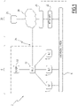
- Figure 1 illustrates an exemplary electrical substation 2 comprising an industrial control system 4 and a plurality of electrical devices 6.
- the electrical devices 6 are configured to perform one or more functions related to the distribution of electrical power, such as interrupting electrical currents, transforming or converting electrical voltages and currents, modifying attributes (such as amplitude or frequency) of electrical voltages and currents, selectively providing reactive power, measuring electrical values, and the like.
- the electrical devices 6 may be connected to a power grid. For example, at least some of the electrical devices 6 are interfaced with one or more power lines, such as medium voltage (MV) power lines.
- MV medium voltage
- the electrical devices 6 may include voltage transformers, power factor compensation (PFC) devices, electrical switchgear devices such as breakers or switches or relays, or any suitable electrical power management system.
- PFC power factor compensation
- electrical switchgear devices such as breakers or switches or relays, or any suitable electrical power management system.
- the electrical devices 6 may be outfitted with one or more sensor, such as voltage sensors, current sensors, power meters, temperature sensors, sensors configured to measure an internal state (such as a position of a moving part) of the electrical device, and more generally, any sensor capable of measuring relevant physical or environmental values.
- sensor such as voltage sensors, current sensors, power meters, temperature sensors, sensors configured to measure an internal state (such as a position of a moving part) of the electrical device, and more generally, any sensor capable of measuring relevant physical or environmental values.
- the industrial control system 4 is coupled to at least some of the electrical devices 6 in order to automatically oversee the operation of the substation 2, for example to enable remote supervision and control of the substation 2.
- the electrical devices 6 may be actuators (e.g., they perform one or more functions in response to a command issued by the control system 4) and/or sensors (e.g., they generate and send data to the control system 4).
- the industrial control system 4 is a SCADA system.
- control system 4 may comprise one or more control devices 8 such as Intelligent Electrical Devices (IED), a main controller 10 and a supervisory device 12.
- IED Intelligent Electrical Devices
- main controller 10 a main controller 10
- supervisory device 12 a supervisory device
- each device 8 is an electronic controller configured to be associated to (e.g., directly interfaced with) one or more electrical devices 6, said controller 8 being configured to receive data and/or issue commands to the connected electrical device(s) 6.
- Each device 8 is further connected to the main controller 10 and is preferably configured to forward data to the controller 10 and/or receive, from the controller 10, data and/or command signals to be relayed to one or more devices 6.
- one or more electrical devices 6 may comprise embedded control circuitry similar to the controller 8. Thus, said devices 6 may be directly interfaced with the main controller 10. In other words, some electrical devices 6 may be connected directly to the controller 10, and some other electrical devices 6 could be connected to the main controller 10 through a control device 8.
- the main controller 10 may comprise electronic circuitry configured to perform various operations, and may include a processor and a memory device (or any suitable non-transitory computer readable data storage media).
- the memory device has program instructions or computer code stored therein for automatically performing one or more of the functions described herein when said program instructions or computer code are executed by the processor.
- the processor is a generic processor, such as a microprocessor or a microcontroller, or a specific purpose processor such as a digital signal processor (DSP) or a graphical processor unit (GPU).
- DSP digital signal processor
- GPU graphical processor unit
- one or more functions of the controller 10 could be implemented by an application-specific integrated circuit (ASIC) or by a field-programmable gate array (FPGA), or by analog circuitry.
- ASIC application-specific integrated circuit
- FPGA field-programmable gate array
- the controller 10 is a programmable logic controller (PLC) or a remote terminal unit (RTU).
- PLC programmable logic controller
- RTU remote terminal unit
- the electrical devices 6 and the control devices 8 are connected to the main controller 10 through wired communication links, such as electrical cables or through a data communication bus.
- the supervisory system 12 is based on site or based in a remote location, and comprises a computer server or a computer workstation connected to the main controller 10, preferably through a secure communications link.
- an additional control and/or monitoring system 20 (also named “loT system” in what follows) is associated to the electrical substation 2.
- the additional control and/or monitoring system 20 comprises a wireless sensor network comprising one or more wireless sensors 22.
- a wireless sensor network comprising one or more wireless sensors 22.
- the wireless sensors 22 are deployed in the substation 2.
- the sensors 22 are able to measure physical and/or environmental conditions in the substation 2 and to collect data relating to the operation of the electrical devices 6, such as electrical voltages, currents, power, power factor values, temperatures, or the like.
- the sensors 22 are in communication with a remote software platform 24 through telecommunications networks such as the internet, or a low power wide area network, or the like.
- the remote software platform 24 is hosted on a remote computer server and may be provided as a cloud-based software service.
- the remote software platform 24 may be configured to process data collected by the sensors 22, for example to provide real time analytics of the operating condition of the substation 2.
- the remote software platform 24 may be referred to as "remote server 24".
- the sensors 22 may be wirelessly connected to a local communication gateway device 23 connected to the remote server 24. Data is exchanged between the sensors 22 and the remote server 24 through the local communication gateway device 23.
- the remote server 24 can be accessed by a client device 25, such as a cell phone, or a digital tablet, or a computer, or any appropriate computing device.
- a client device 25 such as a cell phone, or a digital tablet, or a computer, or any appropriate computing device.
- the sensors 22 could be omitted.
- the additional system 20 (and/or the remote server 24) may be interfaced with the industrial control system 4 only to gather data generated by the control devices and/or by the electrical devices 6.
- This setup could, for example, be used to gather data measured by the control system 4 (such as temperature values or the like), for example to enable a third-party service provider to provide services such as real time analytics, without having to add dedicated sensors for this purpose.
- the additional system 20 is independent from the control system 4.
- the additional system 20 operates independently from the control system 4.
- the communications link used by the control system 4 to communicate with the remote server or workstation 12 is different from the communications link established between the sensors 22 and the software platform 24.
- the remote software platform 24 is able to access and collect data collected or stored by the control system 4.
- the main controller 10 is communicatively coupled to the remote software platform 24, through a communication link 26, such as the internet.
- the main controller 10 may be connected to the local communication gateway device 23, although a direct connection to the remote server 24 can also be envisioned, as illustrated in Figure 1 .
- the main controller 10 comprises a first communication interface, for connecting one or more electrical devices 6, and a second communication interface, for connecting the remote software platform 24.
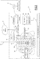
- the main controller 10 is configured to implement a real-time operating system 30 and a real-time database 32.
- the real-time database 32 is configured to store data associated to the connected electrical devices 6, such as data gathered from the electrical devices 6, and/or data describing the internal state of one or more electrical devices 6, and/or data meant to be sent to electrical devices 6 (such as command signals or data collected from other electrical devices 6).
- the database 32 centralizes all real-time data generated and/or consumed by the connected electrical devices 6 during operation of the substation 4.
- the controller 10 is also configured to implement an interface 34 for exchanging data with the connected electrical devices 6, said interface 34 being coupled to the database 32.
- the controller 10 is able to be interfaced to electrical devices 6 (eventually through controllers 8) through a wide range of physical media and industrial communication protocols.
- the interface 34 may comprise one or more interface modules (also named device modules) each adapted to handle communication with at least one connected electrical device 6 according to a predefined communication protocol.
- the interface modules are numbered 341 through 348in the example illustrated on Figure 2 .
- said industrial communication protocols may include at least one of the following protocols and technologies: IEC standards such as IEC60870-5-101, IEC60870-5-103 or IEC60870-5-104, Modbus, Ethernet, Industrial Ethernet, DNP3, or the like.
- IEC standards such as IEC60870-5-101, IEC60870-5-103 or IEC60870-5-104, Modbus, Ethernet, Industrial Ethernet, DNP3, or the like.
- the interface 34 can also be adapted (for example through local acquisition module 348) to accommodate electrical devices 6 that are connected to the module 10 through a non-standard or proprietary physical media or protocol (such as module 347 in the illustrated example).
- the interface modules 341-348 are implemented in the main controller 10 by suitable software code executed by the operating system 30 and/or by electronic circuitry.
- Configuration files 38 may be stored in a memory of the main controller 10.
- the configuration files 38 may be used to define configuration parameters and options related to the electrical devices 6 (e.g., to define a list of connected devices 6, and/or to define parameters of the communication links between the devices 6 and the controller 10).
- the modules 341-348 may read the device configuration files 38 in order to establish and operate the communication link between the main controller 10 and the electrical devices 6.
- a configuration file 38 is defined for each module 341-348, or for each device 6.
- the configuration files 38 may be structured computer files, such as XML files (Extensible Markup Language), or JSON files (Javascript Object Notation), or any appropriate data structure.
- interface 34 could be implemented differently.
- the interface 34 could be compatible with only some of the aforementioned protocols and technologies, or with other protocols and technologies. A different number of protocols could be used.
- the database 32 centralizes, in real time, the information exchanged between the connected electrical devices 6 and the control system 4.
- each entry of the database 32 may correspond to an abstracted entity capable of generating data and/or consuming data (e.g., a sensor generates data, and an actuator consumes data, such as set point values or command signals).
- an abstracted entity capable of generating data and/or consuming data (e.g., a sensor generates data, and an actuator consumes data, such as set point values or command signals).
- Said abstracted entity may, for example, correspond to an electrical device 6, or to a sensor coupled to said electrical device 6, or to an actuator coupled to said electrical device 6.
- An electrical device 6 connected to the control system 4 can be represented by one or more entries in the database if said electrical device 6 comprises one or more sensors or actuator.
- the information (or data) stored in each entry in the database may include set point values and/or command signals (such as a command to close or open a switchgear device) and/or measured values (for example, values of physical or electrical conditions measured by sensors).
- the data may also comprise a source address or a destination address for addressing the device on the corresponding communication link, and/or an identifier for identifying of the corresponding entity or device.
- writing and reading access to the database 32 is controlled by the interface 34.
- the database 32 can be seamlessly updated in real time with information exchanged between the different electrical devices 6 over the different communication links.
- the interface 34 is configured to provide an advanced programming interface (API) 340 configured to allow a third party entity (such as the additional system 20, or the remote server 24) to request data from the database 32, while preventing said third party entities from writing data into the database 32.
- API advanced programming interface
- the advanced programming interface 340 acts as a gateway for interfacing third-party entities and provides only read access to the database 32.
- the advanced programming interface 340 is, for example, implemented by program code executed by the processor of the controller 10.
- the advanced programming interface 340 comprises one or more public functions or methods adapted to be called from the additional system 20, for example from applications (such as IoT related applications) running on the controller 10 and/or on the remote platform 24. Said public functions or methods are configured to interact with the database 32, for example through internal private functions and/or methods implemented in the advanced programming interface.
- the advanced programming interface 340 is devoid of (i.e., does not comprise) any public function or method for writing data in the database 32.
- the advanced programming interface 340 may be configured to grant read access to only some part of the data stored in the database 32, e.g. by providing public functions and/or methods configured to give access only to some specific data stored in the database 32. This selective access could be defined based on a security policy defined by an administrator of the control system 4, and/or based on security credentials provided by the additional system 20.
- the advanced programming interface 340 protects the contents of the database 32 from unauthorized interference from third party systems and/or vendors. Said third party systems and/or vendors are nonetheless able to read data from the database 32, to an extent allowed by the administrator of the system 2. Thus, the additional system 20 can be safely interfaced with the industrial control system 4.
- the controller 10 may be further configured to implement a user interface 36 for allowing a trusted user to access at least some of the data stored in the database 32.
- the user interface 36 may comprise a web server 360, as well as various functions to support the operation of the web server 360, such as synchronization 362 and communication 364 functions.
- the user interface 36 can be omitted in most embodiments.
- the additional system 20 comprises a software application 42, configured to run the operating system 30 of the main controller 10.
- the application 42 may configured to request read access to the database 32 in order to acquire data stored in the database 32 and send at least some of the acquired data to the remote software platform 24.
- the application 42 may be developed by third party vendors with the purpose of interacting with the remote server 24 and, where applicable, with the sensors 22.
- the additional system 20 comprises an acquisition interface 40 configured to connect the wireless sensors 22 to the software application 42.
- the interface 40 could be omitted.
- the application 42 may be further configured to interact with various services and elements provided by the additional system 20, such as a webserver 44, and may be configured to generate log files 46 and/or read configuration files 48, these examples being given only for non-limiting exemplary purposes. It is to be noted that different architectures capable of achieving similar purposes could be used instead in alternative embodiments. For example, the application 42 could be omitted.
- the application 42 (and more generally the additional system 20) is unable to write data in the database 32 (this is depicted by the barrier symbol 50 on Figure 2 ).
- the application 42 may also be prevented from reading some data stored in the database 32, as explained previously.
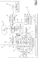
- a main controller 100 suitable for use in the control system 4 is similar to the previously described main controller 10.
- the main controller 100 is further configured to implement an embedded virtual machine 102 comprising a programming language interpreter 104 capable of running one or more software applications.
- the virtual machine 102 is accessible from both the gateway software layer 340 and the remote software platform 24.
- the read requests received from the remote software platform 24 are processed in the virtual machine 102.
- said read requests are processed only in the virtual machine 102.
- the remote software platform 24 is prevented from accessing other parts of the main controller 10. Remote requests can be monitored more easily, and unauthorized requests may be more effectively denied. Furthermore, the execution of remote requests in the controlled execution environment of the virtual machine 102 is the less likely to disrupt the normal operation of the main controller 10.
- using a virtual machine 102 can prevent malicious code sent by a third party entity through the remote server 24 from acting on the data exchanged between the electrical devices 6 and the control system 4. This also facilitates the integration of commercial IoT libraries, since the virtual machine 102 can provide a standardized environment independent from the architecture of the controller 10 and of the operating system 30.
- the contents of the database 32 are even more protected from unauthorized interference emanating from the additional control system 20 (as illustrated by the symbols 106 and 108 on Figure 3 ).
- main controller 100 is similar or identical to the operation of embodiments of the main controller 10.
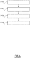
- a read request is received by the controller 10 from the additional system 20, for example from the remote server or from the application 42.
- the read request comprises a call to the application programming interface 340.
- the read request may be analyzed by the interface 340 to determine whether it is allowable or not.
- the read request is accepted by the controller 10.
- the controller 10 retrieves the requested data from the database, for example by calling internal private functions and/or methods of the interface 340 that are responsible for interacting with the database 32.
- the requested data is transmitted to the additional system 20 (e.g., is sent to the remote server 24 or to the application 42).
- the method steps described above could be executed in a different order.
- One or several method steps could be omitted or replaced by equivalent steps, or combined or dissociated into different method steps.
- the disclosed exemplary embodiment is not intended to be limiting and does not prevent other methods steps to be executed without departing from the scope of the claimed subject matter.
Landscapes
- Engineering & Computer Science (AREA)
- Business, Economics & Management (AREA)
- Computer Networks & Wireless Communication (AREA)
- Signal Processing (AREA)
- General Physics & Mathematics (AREA)
- Physics & Mathematics (AREA)
- Computing Systems (AREA)
- Health & Medical Sciences (AREA)
- General Engineering & Computer Science (AREA)
- Economics (AREA)
- Manufacturing & Machinery (AREA)
- Quality & Reliability (AREA)
- Automation & Control Theory (AREA)
- General Health & Medical Sciences (AREA)
- General Business, Economics & Management (AREA)
- Power Engineering (AREA)
- Computer Security & Cryptography (AREA)
- Tourism & Hospitality (AREA)
- Theoretical Computer Science (AREA)
- Strategic Management (AREA)
- Primary Health Care (AREA)
- Marketing (AREA)
- Human Resources & Organizations (AREA)
- Water Supply & Treatment (AREA)
- Public Health (AREA)
- Development Economics (AREA)
- Medical Informatics (AREA)
- Computer Hardware Design (AREA)
- Accounting & Taxation (AREA)
- Selective Calling Equipment (AREA)
- Remote Monitoring And Control Of Power-Distribution Networks (AREA)
Abstract
Description
- The present disclosure relates to industrial control systems and associated methods, and is especially applicable to electrical substations.
- Electrical substations are key elements of electrical transmission and distribution networks. They play a critical role in allowing electrical utilities to deliver electric power to their customers in a safe and reliable way.
- Electrical substations usually comprise various electrical devices such as transformers and electrical switchgear devices connected to a power grid. Most electrical substations also comprise an industrial control system overseeing the operation of the substation in order to enable remote supervision and control of the substation.
- Many commonly used industrial control systems, such as SCADA (Supervisory Control And Data Acquisition) systems, often have dedicated sensors, actuators, communication lines, programmable logic controllers, remote terminal units, and the like, interfacing with local equipment to allow remote control and monitoring of the substation through secure communication channels.
- More recently, control and/or monitoring systems based on so-called "Internet of Things" (IoT) devices have been proposed to improve the operation of electrical substations by offering novel services, such as predictive maintenance services and real-time analytics.
- For example, wireless sensor networks could be deployed in substations to gather data that cannot be accessed through existing industrial control systems. The gathered data is then sent to a remote server connected for further processing.
- In some applications, the remote server could be advantageously interfaced with the industrial control system in order to gather data generated by the control devices and/or by the electrical devices, for example to enable a third-party service provider to provide services such as real time analytics.
- However, interfacing loT systems with existing industrial control systems may raise significant security issues. One reason is that loT networked sensors and systems are permanently connected to public global telecommunication networks such as the Internet and often rely on software and online platforms provided by third-party vendors. On the other hand, electrical substations are strategic assets and they cannot be allowed to suffer outages, disruption, or data loss resulting from unauthorized access to the local industrial control system.
- It is therefore desirable to provide solutions to interface third party systems with industrial control systems in electrical substations while preventing unauthorized access to data, resources and equipment by third parties.
- An aspect of the invention relates to an electronic controller for an industrial control system, said electronic controller comprising:
- a first communication interface configured to be connected to at least one electrical device of an electrical substation,
- a second communication interface configured to be connected to an additional control system,
- a real-time database configured to store data exchanged with at least one electrical device of the electrical substation,
- In other embodiments, the invention may advantageously comprise one or more of the following technical features, considered alone or according to all possible technical combinations:
- the electronic controller is configured to implement a software application programming interface comprising a public method authorizing the additional control system to read data from the database.
- the electronic controller is configured to execute steps of:
- receiving a read request from the additional control system, said read request comprising a call to the application programming interface,
- accepting the read request,
- fetching the requested data from the database,
- sending the requested data to the additional control system.
- the electronic controller is further configured to implement a virtual machine configured to process read requests received from the additional control system.
- the electronic controller is a programmable logic controller.
- According to another aspect, an electrical substation, comprises:
- one or more electrical devices,
- an industrial control system comprising an electronic controller according to any previous claim and a supervisory device, the electronic controller being connected to at least some of the electrical devices and to the additional control system.
- According to another aspect, one or more wireless sensors are placed in the electrical substation and are configured to send data to the additional control system.
- According to another aspect, a method comprises, by an electronic controller connected to one or more electrical device of an electrical substation:
- receiving a read request from a additional control system, said read request comprising a call to the application programming interface,
- accepting the read request,
- fetching the requested data from the database,
- sending the requested data to the additional control system.
- The invention will be further understood upon reading the following description, provided solely as a non-limiting example, and made in reference to the appended drawings, in which:
-
Fig. 1 is a simplified block diagram of an electrical substation comprising an industrial control system according to embodiments of the invention; -
Fig. 2 is a block diagram of an industrial control system of an electrical substation according to an embodiment; -
Fig. 3 is a block diagram of an industrial control system of an electrical substation according to another embodiment; -
Fig. 4 is a flow chart depicting an exemplary method of operation implemented by the industrial control system ofFig. 2 . -
Figure 1 illustrates an exemplaryelectrical substation 2 comprising anindustrial control system 4 and a plurality ofelectrical devices 6. - In many embodiments, the
electrical devices 6 are configured to perform one or more functions related to the distribution of electrical power, such as interrupting electrical currents, transforming or converting electrical voltages and currents, modifying attributes (such as amplitude or frequency) of electrical voltages and currents, selectively providing reactive power, measuring electrical values, and the like. - The
electrical devices 6 may be connected to a power grid. For example, at least some of theelectrical devices 6 are interfaced with one or more power lines, such as medium voltage (MV) power lines. - For example, the
electrical devices 6 may include voltage transformers, power factor compensation (PFC) devices, electrical switchgear devices such as breakers or switches or relays, or any suitable electrical power management system. - In many embodiments, the
electrical devices 6 may be outfitted with one or more sensor, such as voltage sensors, current sensors, power meters, temperature sensors, sensors configured to measure an internal state (such as a position of a moving part) of the electrical device, and more generally, any sensor capable of measuring relevant physical or environmental values. - The
industrial control system 4 is coupled to at least some of theelectrical devices 6 in order to automatically oversee the operation of thesubstation 2, for example to enable remote supervision and control of thesubstation 2. - The
electrical devices 6 may be actuators (e.g., they perform one or more functions in response to a command issued by the control system 4) and/or sensors (e.g., they generate and send data to the control system 4). - In many embodiments, the
industrial control system 4 is a SCADA system. - For example, as shown in the exemplary embodiment of
Figure 1 , thecontrol system 4 may comprise one ormore control devices 8 such as Intelligent Electrical Devices (IED), amain controller 10 and asupervisory device 12. - For example, each
device 8 is an electronic controller configured to be associated to (e.g., directly interfaced with) one or moreelectrical devices 6, saidcontroller 8 being configured to receive data and/or issue commands to the connected electrical device(s) 6. - Each
device 8 is further connected to themain controller 10 and is preferably configured to forward data to thecontroller 10 and/or receive, from thecontroller 10, data and/or command signals to be relayed to one ormore devices 6. - In some embodiments, one or more
electrical devices 6 may comprise embedded control circuitry similar to thecontroller 8. Thus, saiddevices 6 may be directly interfaced with themain controller 10. In other words, someelectrical devices 6 may be connected directly to thecontroller 10, and some otherelectrical devices 6 could be connected to themain controller 10 through acontrol device 8. - The
main controller 10 may comprise electronic circuitry configured to perform various operations, and may include a processor and a memory device (or any suitable non-transitory computer readable data storage media). - The memory device has program instructions or computer code stored therein for automatically performing one or more of the functions described herein when said program instructions or computer code are executed by the processor.
- For example, the processor is a generic processor, such as a microprocessor or a microcontroller, or a specific purpose processor such as a digital signal processor (DSP) or a graphical processor unit (GPU). In alternative embodiments, one or more functions of the
controller 10 could be implemented by an application-specific integrated circuit (ASIC) or by a field-programmable gate array (FPGA), or by analog circuitry. - For example, the
controller 10 is a programmable logic controller (PLC) or a remote terminal unit (RTU). - In preferred embodiments, the
electrical devices 6 and thecontrol devices 8 are connected to themain controller 10 through wired communication links, such as electrical cables or through a data communication bus. - In many embodiments, the
supervisory system 12 is based on site or based in a remote location, and comprises a computer server or a computer workstation connected to themain controller 10, preferably through a secure communications link. - As visible on
Figure 1 , an additional control and/or monitoring system 20 (also named "loT system" in what follows) is associated to theelectrical substation 2. - The additional control and/or
monitoring system 20 comprises a wireless sensor network comprising one ormore wireless sensors 22. Preferably, at least some of thewireless sensors 22 are deployed in thesubstation 2. - For example, the
sensors 22 are able to measure physical and/or environmental conditions in thesubstation 2 and to collect data relating to the operation of theelectrical devices 6, such as electrical voltages, currents, power, power factor values, temperatures, or the like. - The
sensors 22 are in communication with aremote software platform 24 through telecommunications networks such as the internet, or a low power wide area network, or the like. - In practice, the
remote software platform 24 is hosted on a remote computer server and may be provided as a cloud-based software service. Theremote software platform 24 may be configured to process data collected by thesensors 22, for example to provide real time analytics of the operating condition of thesubstation 2. In what follows, theremote software platform 24 may be referred to as "remote server 24". - In many embodiments, the
sensors 22 may be wirelessly connected to a localcommunication gateway device 23 connected to theremote server 24. Data is exchanged between thesensors 22 and theremote server 24 through the localcommunication gateway device 23. - In some examples, the
remote server 24 can be accessed by aclient device 25, such as a cell phone, or a digital tablet, or a computer, or any appropriate computing device. - In some alternative embodiments, the
sensors 22 could be omitted. For example, the additional system 20 (and/or the remote server 24) may be interfaced with theindustrial control system 4 only to gather data generated by the control devices and/or by theelectrical devices 6. This setup could, for example, be used to gather data measured by the control system 4 (such as temperature values or the like), for example to enable a third-party service provider to provide services such as real time analytics, without having to add dedicated sensors for this purpose. - In most embodiments, the
additional system 20 is independent from thecontrol system 4. For example, theadditional system 20 operates independently from thecontrol system 4. Preferably, the communications link used by thecontrol system 4 to communicate with the remote server orworkstation 12 is different from the communications link established between thesensors 22 and thesoftware platform 24. - In many embodiments, the
remote software platform 24 is able to access and collect data collected or stored by thecontrol system 4. For example, themain controller 10 is communicatively coupled to theremote software platform 24, through acommunication link 26, such as the internet. - In practice, the
main controller 10 may be connected to the localcommunication gateway device 23, although a direct connection to theremote server 24 can also be envisioned, as illustrated inFigure 1 . - For example, the
main controller 10 comprises a first communication interface, for connecting one or moreelectrical devices 6, and a second communication interface, for connecting theremote software platform 24. - As shown on the block diagram of
Figure 2 , themain controller 10 is configured to implement a real-time operating system 30 and a real-time database 32. - The real-
time database 32 is configured to store data associated to the connectedelectrical devices 6, such as data gathered from theelectrical devices 6, and/or data describing the internal state of one or moreelectrical devices 6, and/or data meant to be sent to electrical devices 6 (such as command signals or data collected from other electrical devices 6). - In other words, the
database 32 centralizes all real-time data generated and/or consumed by the connectedelectrical devices 6 during operation of thesubstation 4. - The
controller 10 is also configured to implement aninterface 34 for exchanging data with the connectedelectrical devices 6, saidinterface 34 being coupled to thedatabase 32. - In the illustrated exemplary embodiment, the
controller 10 is able to be interfaced to electrical devices 6 (eventually through controllers 8) through a wide range of physical media and industrial communication protocols. Thus, theinterface 34 may comprise one or more interface modules (also named device modules) each adapted to handle communication with at least one connectedelectrical device 6 according to a predefined communication protocol. The interface modules are numbered 341 through 348in the example illustrated onFigure 2 . - For example, said industrial communication protocols may include at least one of the following protocols and technologies: IEC standards such as IEC60870-5-101, IEC60870-5-103 or IEC60870-5-104, Modbus, Ethernet, Industrial Ethernet, DNP3, or the like.
- The
interface 34 can also be adapted (for example through local acquisition module 348) to accommodateelectrical devices 6 that are connected to themodule 10 through a non-standard or proprietary physical media or protocol (such asmodule 347 in the illustrated example). - For example, the interface modules 341-348 are implemented in the
main controller 10 by suitable software code executed by theoperating system 30 and/or by electronic circuitry. - Configuration files 38 may be stored in a memory of the
main controller 10. The configuration files 38 may be used to define configuration parameters and options related to the electrical devices 6 (e.g., to define a list ofconnected devices 6, and/or to define parameters of the communication links between thedevices 6 and the controller 10). - For example, the modules 341-348 may read the device configuration files 38 in order to establish and operate the communication link between the
main controller 10 and theelectrical devices 6. - In some examples, a
configuration file 38 is defined for each module 341-348, or for eachdevice 6. The configuration files 38 may be structured computer files, such as XML files (Extensible Markup Language), or JSON files (Javascript Object Notation), or any appropriate data structure. - It is to be understood that the embodiments described above are given for illustrative purposes only, and that in practice the
interface 34 could be implemented differently. For example, theinterface 34 could be compatible with only some of the aforementioned protocols and technologies, or with other protocols and technologies. A different number of protocols could be used. - In exemplary embodiments, the
database 32 centralizes, in real time, the information exchanged between the connectedelectrical devices 6 and thecontrol system 4. - For example, each entry of the
database 32 may correspond to an abstracted entity capable of generating data and/or consuming data (e.g., a sensor generates data, and an actuator consumes data, such as set point values or command signals). - Said abstracted entity may, for example, correspond to an
electrical device 6, or to a sensor coupled to saidelectrical device 6, or to an actuator coupled to saidelectrical device 6. Anelectrical device 6 connected to thecontrol system 4 can be represented by one or more entries in the database if saidelectrical device 6 comprises one or more sensors or actuator. - The information (or data) stored in each entry in the database may include set point values and/or command signals (such as a command to close or open a switchgear device) and/or measured values (for example, values of physical or electrical conditions measured by sensors). The data may also comprise a source address or a destination address for addressing the device on the corresponding communication link, and/or an identifier for identifying of the corresponding entity or device.
- Preferably, writing and reading access to the
database 32 is controlled by theinterface 34. Thus, thedatabase 32 can be seamlessly updated in real time with information exchanged between the differentelectrical devices 6 over the different communication links. - According to aspects of the invention, the
interface 34 is configured to provide an advanced programming interface (API) 340 configured to allow a third party entity (such as theadditional system 20, or the remote server 24) to request data from thedatabase 32, while preventing said third party entities from writing data into thedatabase 32. - In other words, the
advanced programming interface 340 acts as a gateway for interfacing third-party entities and provides only read access to thedatabase 32. - The
advanced programming interface 340 is, for example, implemented by program code executed by the processor of thecontroller 10. - In many embodiments, the
advanced programming interface 340 comprises one or more public functions or methods adapted to be called from theadditional system 20, for example from applications (such as IoT related applications) running on thecontroller 10 and/or on theremote platform 24. Said public functions or methods are configured to interact with thedatabase 32, for example through internal private functions and/or methods implemented in the advanced programming interface. - Most notably, the
advanced programming interface 340 is devoid of (i.e., does not comprise) any public function or method for writing data in thedatabase 32. - In some optional embodiments, the
advanced programming interface 340 may be configured to grant read access to only some part of the data stored in thedatabase 32, e.g. by providing public functions and/or methods configured to give access only to some specific data stored in thedatabase 32. This selective access could be defined based on a security policy defined by an administrator of thecontrol system 4, and/or based on security credentials provided by theadditional system 20. - In conclusion, the
advanced programming interface 340 protects the contents of thedatabase 32 from unauthorized interference from third party systems and/or vendors. Said third party systems and/or vendors are nonetheless able to read data from thedatabase 32, to an extent allowed by the administrator of thesystem 2. Thus, theadditional system 20 can be safely interfaced with theindustrial control system 4. - In some optional embodiments illustrated on the example of
Figure 2 , thecontroller 10 may be further configured to implement auser interface 36 for allowing a trusted user to access at least some of the data stored in thedatabase 32. For example, theuser interface 36 may comprise aweb server 360, as well as various functions to support the operation of theweb server 360, such assynchronization 362 andcommunication 364 functions. Theuser interface 36 can be omitted in most embodiments. - In many exemplary embodiments, the
additional system 20 comprises asoftware application 42, configured to run theoperating system 30 of themain controller 10. Theapplication 42 may configured to request read access to thedatabase 32 in order to acquire data stored in thedatabase 32 and send at least some of the acquired data to theremote software platform 24. - In practice, the
application 42 may be developed by third party vendors with the purpose of interacting with theremote server 24 and, where applicable, with thesensors 22. - In the illustrated exemplary embodiment, the
additional system 20 comprises anacquisition interface 40 configured to connect thewireless sensors 22 to thesoftware application 42. In instances wheresensors 22 are not deployed in thesubstation 2, theinterface 40 could be omitted. - The
application 42 may be further configured to interact with various services and elements provided by theadditional system 20, such as awebserver 44, and may be configured to generatelog files 46 and/or read configuration files 48, these examples being given only for non-limiting exemplary purposes. It is to be noted that different architectures capable of achieving similar purposes could be used instead in alternative embodiments. For example, theapplication 42 could be omitted. - Due to the implementation of the read-only functions in the
advanced programming interface 340, the application 42 (and more generally the additional system 20) is unable to write data in the database 32 (this is depicted by thebarrier symbol 50 onFigure 2 ). - In some embodiments, the
application 42 may also be prevented from reading some data stored in thedatabase 32, as explained previously. - Another embodiment of the
main controller 10 is described in reference toFigure 3 . - In this example, a
main controller 100 suitable for use in thecontrol system 4 is similar to the previously describedmain controller 10. Themain controller 100 is further configured to implement an embeddedvirtual machine 102 comprising aprogramming language interpreter 104 capable of running one or more software applications. - For example, the
virtual machine 102 is accessible from both thegateway software layer 340 and theremote software platform 24. The read requests received from theremote software platform 24 are processed in thevirtual machine 102. Preferably, said read requests are processed only in thevirtual machine 102. - Thus, the
remote software platform 24 is prevented from accessing other parts of themain controller 10. Remote requests can be monitored more easily, and unauthorized requests may be more effectively denied. Furthermore, the execution of remote requests in the controlled execution environment of thevirtual machine 102 is the less likely to disrupt the normal operation of themain controller 10. - For example, using a
virtual machine 102 can prevent malicious code sent by a third party entity through theremote server 24 from acting on the data exchanged between theelectrical devices 6 and thecontrol system 4. This also facilitates the integration of commercial IoT libraries, since thevirtual machine 102 can provide a standardized environment independent from the architecture of thecontroller 10 and of theoperating system 30. - Thus, in this embodiment, the contents of the
database 32 are even more protected from unauthorized interference emanating from the additional control system 20 (as illustrated by thesymbols Figure 3 ). - Aside from these differences, the operation of the
main controller 100 is similar or identical to the operation of embodiments of themain controller 10. - An exemplary method of operation of the
controller 10 is now described in reference toFigure 4 . For example, the program code stored in memory of themain controller 10 causes the processor to execute the following steps. - At block S1000, a read request is received by the
controller 10 from theadditional system 20, for example from the remote server or from theapplication 42. For example, the read request comprises a call to theapplication programming interface 340. - At block S1002, the read request may be analyzed by the
interface 340 to determine whether it is allowable or not. In the illustrated example, the read request is accepted by thecontroller 10. - In response, at block S1004, the
controller 10 retrieves the requested data from the database, for example by calling internal private functions and/or methods of theinterface 340 that are responsible for interacting with thedatabase 32. - At block S1006, the requested data is transmitted to the additional system 20 (e.g., is sent to the
remote server 24 or to the application 42). - In other embodiments, the method steps described above could be executed in a different order. One or several method steps could be omitted or replaced by equivalent steps, or combined or dissociated into different method steps. The disclosed exemplary embodiment is not intended to be limiting and does not prevent other methods steps to be executed without departing from the scope of the claimed subject matter.
- The embodiments and alternatives described above may be combined with each other in order to create new embodiments.
- The project leading to this patent application has received funding from the European Union's Horizon 2020 research and innovation programme under grant agreement Nº 731211.
Claims (8)
wherein the electronic controller is configured to allow the additional control and/or monitoring system (20) to read data from said database and to prevent the additional control and/or monitoring system (20) from writing into said database.
Priority Applications (3)
| Application Number | Priority Date | Filing Date | Title |
|---|---|---|---|
| EP20306310.2A EP3993340A1 (en) | 2020-11-02 | 2020-11-02 | Iot gateway for industrial control systems, associated devices, systems and methods |
| CN202111230635.7A CN114448085A (en) | 2020-11-02 | 2021-10-22 | IOT gateway for industrial control system, associated apparatus, system and method |
| US17/511,712 US20220137600A1 (en) | 2020-11-02 | 2021-10-27 | Iot gateway for industrial control systems, associated devices, systems and methods |
Applications Claiming Priority (1)
| Application Number | Priority Date | Filing Date | Title |
|---|---|---|---|
| EP20306310.2A EP3993340A1 (en) | 2020-11-02 | 2020-11-02 | Iot gateway for industrial control systems, associated devices, systems and methods |
Publications (1)
| Publication Number | Publication Date |
|---|---|
| EP3993340A1 true EP3993340A1 (en) | 2022-05-04 |
Family
ID=74105789
Family Applications (1)
| Application Number | Title | Priority Date | Filing Date |
|---|---|---|---|
| EP20306310.2A Pending EP3993340A1 (en) | 2020-11-02 | 2020-11-02 | Iot gateway for industrial control systems, associated devices, systems and methods |
Country Status (3)
| Country | Link |
|---|---|
| US (1) | US20220137600A1 (en) |
| EP (1) | EP3993340A1 (en) |
| CN (1) | CN114448085A (en) |
Families Citing this family (4)
| Publication number | Priority date | Publication date | Assignee | Title |
|---|---|---|---|---|
| JP6586076B2 (en) * | 2013-03-15 | 2019-10-02 | フルークコーポレイションFluke Corporation | Visual audiovisual annotation on infrared images using a separate wireless mobile device |
| US11695772B1 (en) * | 2022-05-03 | 2023-07-04 | Capital One Services, Llc | System and method for enabling multiple auxiliary use of an access token of a user by another entity to facilitate an action of the user |
| CN116131987B (en) * | 2023-02-14 | 2026-04-07 | 万洲电气股份有限公司 | An edge computing gateway device with clock synchronization calibration function |
| CN116389521B (en) * | 2023-02-28 | 2025-11-28 | 上海明华电力科技有限公司 | Interface platform and method for bridging SCADA system and third party system of new energy station |
Citations (1)
| Publication number | Priority date | Publication date | Assignee | Title |
|---|---|---|---|---|
| CN107622342B (en) * | 2017-08-31 | 2020-08-14 | 国网辽宁省电力有限公司电力科学研究院 | MVC (model view controller) architecture-based distribution network area data analysis system |
Family Cites Families (125)
| Publication number | Priority date | Publication date | Assignee | Title |
|---|---|---|---|---|
| US5513061A (en) * | 1993-12-09 | 1996-04-30 | Long Island Lighting Company | Apparatus and method for distributing electrical power |
| US6968459B1 (en) * | 1999-12-15 | 2005-11-22 | Imation Corp. | Computing environment having secure storage device |
| US20020029097A1 (en) * | 2000-04-07 | 2002-03-07 | Pionzio Dino J. | Wind farm control system |
| US20080143515A1 (en) * | 2001-06-01 | 2008-06-19 | Colorado Medtech, Inc. | Information technology system for health care environments |
| US20030177367A1 (en) * | 2002-03-14 | 2003-09-18 | International Business Machines Corporation | Controlling access to a disk drive in a computer system running multiple operating systems |
| GB0220899D0 (en) * | 2002-09-09 | 2002-10-16 | Univ Liverpool | Automation system for information management, condition monitoring and real-time control of distributed industrial systems |
| AU2003257357A1 (en) * | 2002-09-13 | 2004-04-30 | Barix Ag | Method and device for controlling the thermal balance in buildings |
| US7107483B2 (en) * | 2002-11-15 | 2006-09-12 | Lsi Logic Corporation | Apparatus and method for enhancing data availability by leveraging primary/backup data storage volumes |
| JP2004356785A (en) * | 2003-05-28 | 2004-12-16 | Nec Corp | Physical quantity monitoring control system and mobile information terminal used for the same |
| US7013203B2 (en) * | 2003-10-22 | 2006-03-14 | General Electric Company | Wind turbine system control |
| US7188230B2 (en) * | 2005-02-15 | 2007-03-06 | Hitachi, Ltd. | Method of assuring data integrity on storage volumes |
| US7929749B1 (en) * | 2006-09-25 | 2011-04-19 | Cummins-Allison Corp. | System and method for saving statistical data of currency bills in a currency processing device |
| KR100827571B1 (en) * | 2006-10-31 | 2008-05-07 | 한국전력공사 | SCAD Online FAC Simulator System |
| EP2101387A1 (en) * | 2008-03-10 | 2009-09-16 | ABB Research Ltd | Controlling distribution of electrical power |
| US8327130B2 (en) * | 2007-09-25 | 2012-12-04 | Rockwell Automation Technologies, Inc. | Unique identification of entities of an industrial control system |
| US9917436B2 (en) * | 2007-10-30 | 2018-03-13 | General Electric Company | System and method for control of power distribution |
| JP2009187341A (en) * | 2008-02-07 | 2009-08-20 | Fuji Xerox Co Ltd | Information processing program and information processor |
| US7953709B2 (en) * | 2008-03-27 | 2011-05-31 | Emc Corporation | Systems and methods for a read only mode for a portion of a storage system |
| US20090265042A1 (en) * | 2008-04-17 | 2009-10-22 | Mollenkopf James D | System and Method for Providing Voltage Regulation in a Power Distribution System |
| WO2010120549A2 (en) * | 2009-03-31 | 2010-10-21 | Ecrio, Inc. | System, method and apparatus for providing functions to applications on a digital electronic device |
| US9270679B2 (en) * | 2009-06-23 | 2016-02-23 | Yahoo! Inc. | Dynamic access control lists |
| US8812796B2 (en) * | 2009-06-26 | 2014-08-19 | Microsoft Corporation | Private memory regions and coherence optimizations |
| US8426736B2 (en) * | 2009-07-17 | 2013-04-23 | The Invention Science Fund I Llc | Maintaining insulators in power transmission systems |
| US20110082591A1 (en) * | 2009-08-20 | 2011-04-07 | JMC Enterprises, Inc. | Remote management of storage facilities |
| JP5458744B2 (en) * | 2009-08-25 | 2014-04-02 | 沖電気工業株式会社 | Presence information providing method and system |
| US8458808B2 (en) * | 2011-01-07 | 2013-06-04 | Mastercard International Incorporated | Premium access to open application programming interface systems and methods |
| CA2862904C (en) * | 2011-02-01 | 2020-07-28 | S&C Electric Company | Distributed energy storage system and method of distributing energy |
| US8452461B2 (en) * | 2011-05-10 | 2013-05-28 | First Solar, Inc | Control system for photovoltaic power plant |
| US8893216B2 (en) * | 2011-06-15 | 2014-11-18 | Cisco Technology, Inc. | Security measures for the smart grid |
| US9313172B1 (en) * | 2011-06-29 | 2016-04-12 | Amazon Technologies, Inc. | Providing access to remote networks via external endpoints |
| US8781638B2 (en) * | 2012-04-27 | 2014-07-15 | Gregory C. Rouse | Campus energy manager |
| US20140143419A1 (en) * | 2011-07-19 | 2014-05-22 | Auckland Uniservices | Control of networks |
| US20130066444A1 (en) * | 2011-09-12 | 2013-03-14 | Bogdan Cristian Popescu | Systems and methods for use in responding to faults in a utility system |
| US20130100868A1 (en) * | 2011-10-20 | 2013-04-25 | Xetawave, Llc | Phase coherent radio |
| US9077756B1 (en) * | 2012-03-05 | 2015-07-07 | Symantec Corporation | Limiting external device access to mobile computing devices according to device type and connection context |
| US9685823B2 (en) * | 2012-03-30 | 2017-06-20 | General Electric Company | Method for calibrating sensors in a power system |
| US20240388631A1 (en) * | 2012-04-13 | 2024-11-21 | View, Inc. | Occupant-centered predictive control of devices in facilities |
| US20230132451A1 (en) * | 2012-04-13 | 2023-05-04 | View, Inc. | Interaction between an enclosure and one or more occupants |
| EP2657803B1 (en) * | 2012-04-27 | 2014-08-06 | AFRISO-Euro-Index GmbH | Room temperature control assembly and method for areas heated with hot water |
| AU2013334489A1 (en) * | 2012-10-24 | 2015-05-14 | Or Technologies Pty Ltd | A device control node, an interface node and a hybrid control system |
| US9244452B2 (en) * | 2012-11-02 | 2016-01-26 | Rockwell Automation Technologies, Inc. | Configuration and monitoring via design diagram representation |
| US9250674B2 (en) * | 2013-01-18 | 2016-02-02 | General Electric Company | Methods and systems for restoring power based on forecasted loads |
| US10706025B2 (en) * | 2013-02-28 | 2020-07-07 | Amazon Technologies, Inc. | Database system providing single-tenant and multi-tenant environments |
| US9979638B2 (en) * | 2013-06-19 | 2018-05-22 | Hcl Technologies Limited | Systems and methods to construct engineering environment supporting API enablement for software defined networking |
| JP5895906B2 (en) * | 2013-07-24 | 2016-03-30 | 横河電機株式会社 | Process control device and system, and soundness determination method thereof |
| US9648143B2 (en) * | 2013-10-03 | 2017-05-09 | Duke Energy Corporation | Methods of processing data corresponding to a device that corresponds to a gas, water, or electric grid, and related devices and computer program products |
| CA2926811C (en) * | 2013-10-07 | 2023-03-21 | Google Inc. | Smart-home hazard detector providing context specific features and/or pre-alarm configurations |
| US10089842B2 (en) * | 2013-10-07 | 2018-10-02 | Google Llc | Smart-home security system with keypad device resistant to anomalous treatment |
| US9853914B1 (en) * | 2014-11-11 | 2017-12-26 | Amdocs Software Systems Limited | System, method, and computer program for selecting at least one new physical element and/or virtual element for use in a system including a network function virtualization orchestrator (NFV-O) |
| US9584482B2 (en) * | 2014-03-03 | 2017-02-28 | Qualcomm Connected Experiences, Inc. | Access control lists for private networks of system agnostic connected devices |
| US10095202B2 (en) * | 2014-03-26 | 2018-10-09 | Rockwell Automation Technologies, Inc. | Multiple controllers configuration management interface for system connectivity |
| WO2015167618A1 (en) * | 2014-04-28 | 2015-11-05 | Kohler Co. | Biofuel power generation systems |
| KR102122913B1 (en) * | 2014-05-30 | 2020-06-26 | 삼성에스디에스 주식회사 | Distributed api proxy system and apapparatus and method for managing traffic in such system |
| KR101729097B1 (en) * | 2014-06-09 | 2017-04-24 | 한국전자통신연구원 | Method for sharing reference data among application programs executed by a plurality of virtual machines and Reference data management apparatus and system therefor |
| JP2017526219A (en) * | 2014-06-18 | 2017-09-07 | センシティ システムズ インコーポレイテッド | Application framework for interactive optical sensor networks |
| US9788039B2 (en) * | 2014-06-23 | 2017-10-10 | Google Inc. | Camera system API for third-party integrations |
| US20150370272A1 (en) * | 2014-06-23 | 2015-12-24 | Google Inc. | Intelligent configuration of a smart environment based on arrival time |
| US20150381737A1 (en) * | 2014-06-30 | 2015-12-31 | Davra Networks Limited | Gateway device and a gateway system for an internet-of-things environment |
| US20170329543A1 (en) * | 2014-10-22 | 2017-11-16 | Hewlett Packard Enterprise Development Lp | Data restoration using block disk presentations |
| US9845789B2 (en) * | 2014-10-23 | 2017-12-19 | General Electric Company | System and method for monitoring and controlling wind turbines within a wind farm |
| US9417897B1 (en) * | 2014-12-05 | 2016-08-16 | Amazon Technologies, Inc. | Approaches for managing virtual instance data |
| GB2533382A (en) * | 2014-12-18 | 2016-06-22 | Cambridge Consultants | Secure file transfer |
| US9935950B2 (en) * | 2015-01-12 | 2018-04-03 | Verisign, Inc. | Systems and methods for establishing ownership and delegation ownership of IOT devices using domain name system services |
| US20160205106A1 (en) * | 2015-01-12 | 2016-07-14 | Verisign, Inc. | Systems and methods for providing iot services |
| JP6356909B2 (en) * | 2015-04-23 | 2018-07-11 | 株式会社東芝 | Client system, client system management method, system controller |
| US20180137440A1 (en) * | 2015-05-16 | 2018-05-17 | Dev Kumar Vaidya | Transport Charter System and a Method Thereof |
| JP2016220174A (en) * | 2015-05-26 | 2016-12-22 | 株式会社東芝 | Home appliance control method and home appliance control device |
| JP6594667B2 (en) * | 2015-06-03 | 2019-10-23 | 株式会社日立製作所 | Communication control device |
| US10185297B2 (en) * | 2015-06-16 | 2019-01-22 | Rockwell Automation Technologies, Inc. | Enhanced wake activation response speeds for industrial control systems |
| US10310461B2 (en) * | 2015-06-29 | 2019-06-04 | S&C Electric Company | Adaptive polling in energy distribution systems with distributed energy storage |
| US20170011318A1 (en) * | 2015-07-09 | 2017-01-12 | Johnson Controls Technology Company | Automated monitoring and service provider recommendation platform for hvac equipment |
| US10742739B2 (en) * | 2015-08-18 | 2020-08-11 | Comcast Cable Communications, Llc | Platform for controlling and operating network connected devices |
| US10216742B2 (en) * | 2015-08-28 | 2019-02-26 | Honeywell International Inc. | Converting data sets in a shared communication environment |
| US10739737B2 (en) * | 2015-09-25 | 2020-08-11 | Intel Corporation | Environment customization |
| WO2017056194A1 (en) * | 2015-09-29 | 2017-04-06 | 株式会社 東芝 | Information device, information communication terminal, and information processing method |
| JP6807556B2 (en) * | 2015-10-01 | 2021-01-06 | パナソニックIpマネジメント株式会社 | Air conditioning control method, air conditioning control device and air conditioning control program |
| US10419540B2 (en) * | 2015-10-05 | 2019-09-17 | Microsoft Technology Licensing, Llc | Architecture for internet of things |
| US10018977B2 (en) * | 2015-10-05 | 2018-07-10 | Savant Systems, Llc | History-based key phrase suggestions for voice control of a home automation system |
| CA2931736C (en) * | 2015-10-29 | 2022-04-19 | Trevor Boicey | Heat energy management system |
| US10645167B2 (en) * | 2015-11-23 | 2020-05-05 | Cybirical, LLC | Distributed setting of network security devices from power system IED settings files |
| US9727623B1 (en) * | 2016-02-05 | 2017-08-08 | Accenture Global Solutions Limited | Integrated developer workflow for data visualization development |
| EP3823242A1 (en) * | 2016-04-06 | 2021-05-19 | Karamba Security | Centralized controller management and anomaly detection |
| US10013570B2 (en) * | 2016-05-09 | 2018-07-03 | International Business Machines Corporation | Data management for a mass storage device |
| CA2969360C (en) * | 2016-06-03 | 2022-06-21 | Maax Bath Inc. | Computer-implemented method and device for controlling a liquid delivery system |
| CN109314395B (en) * | 2016-06-13 | 2022-07-05 | 维斯塔斯风力系统集团公司 | Improvements relating to interconnection of multiple renewable energy power plants |
| US20180020057A1 (en) * | 2016-07-12 | 2018-01-18 | Ananse Incorporated | Method and System for Connecting Heterogeneous Internet of Things Devices for Workflow Automation |
| SG10201700177UA (en) * | 2016-07-13 | 2018-02-27 | Yokogawa Electric Corp | Methods and systems for context based operator assistance for control systems |
| US10320620B2 (en) * | 2016-07-15 | 2019-06-11 | Verizon Patent And Licesing Inc. | Virtual models for access/control of internet of things (IoTs) devices |
| US11531577B1 (en) * | 2016-09-07 | 2022-12-20 | Pure Storage, Inc. | Temporarily limiting access to a storage device |
| US20180084085A1 (en) * | 2016-09-20 | 2018-03-22 | Arrayent, Inc. | Cross platform device virtualization for an iot system |
| US10303883B2 (en) * | 2016-10-25 | 2019-05-28 | Hewlett Packard Enterprise Development Lp | Firmware verification through data ports |
| US10740167B2 (en) * | 2016-12-07 | 2020-08-11 | Electronics And Telecommunications Research Institute | Multi-core processor and cache management method thereof |
| US10642782B2 (en) * | 2016-12-08 | 2020-05-05 | Electronics And Telecommunications Research Institute | Multi-core processor and operation method thereof |
| US10764306B2 (en) * | 2016-12-19 | 2020-09-01 | Sap Se | Distributing cloud-computing platform content to enterprise threat detection systems |
| EP3339754B1 (en) * | 2016-12-22 | 2020-09-09 | Netatmo | System and method for balancing temperature within a building |
| CN108259413B (en) * | 2016-12-28 | 2021-06-01 | 华为技术有限公司 | A method for obtaining certificate and authentication and network device |
| US11128528B2 (en) * | 2016-12-30 | 2021-09-21 | Intel Corporation | Decentralized data storage and processing for IoT devices |
| US11804717B2 (en) * | 2017-05-05 | 2023-10-31 | The Board Of Trustees Of The Leland Stanford Junior University | Systems and methods for coordinating distributed energy storage |
| WO2019040125A1 (en) * | 2017-08-21 | 2019-02-28 | Landmark Graphics Corporation | Integrated surveillance and control |
| US10571880B2 (en) * | 2017-09-20 | 2020-02-25 | General Electric Company | System and method for synchronization of device communication |
| CN107577629B (en) * | 2017-09-25 | 2019-12-31 | 北京因特睿软件有限公司 | A data interface processing method, device, server and medium |
| US20190095517A1 (en) * | 2017-09-27 | 2019-03-28 | Johnson Controls Technology Company | Web services platform with integration of data into smart entities |
| US11120012B2 (en) * | 2017-09-27 | 2021-09-14 | Johnson Controls Tyco IP Holdings LLP | Web services platform with integration and interface of smart entities with enterprise applications |
| US10962945B2 (en) * | 2017-09-27 | 2021-03-30 | Johnson Controls Technology Company | Building management system with integration of data into smart entities |
| EP3704501B1 (en) * | 2017-10-31 | 2026-02-04 | Hitachi Energy Ltd | System and method for analyzing fault data of a power transmission network |
| US10944814B1 (en) * | 2017-12-04 | 2021-03-09 | Amazon Technologies, Inc. | Independent resource scheduling for distributed data processing programs |
| US10621838B2 (en) * | 2017-12-15 | 2020-04-14 | Google Llc | External video clip distribution with metadata from a smart-home environment |
| US11943236B2 (en) * | 2018-04-26 | 2024-03-26 | Hitachi Energy Ltd | Technologies for detecting cyber-attacks against electrical distribution devices |
| US11009252B2 (en) * | 2018-05-07 | 2021-05-18 | Johnson Controls Technology Company | HVAC control system with cost target optimization |
| US11282302B2 (en) * | 2018-05-10 | 2022-03-22 | The Boeing Company | Communications server for monitoring and testing a vehicle |
| US10977381B2 (en) * | 2018-06-28 | 2021-04-13 | Mohammad Mannan | Protection system and method against unauthorized data alteration |
| US10602099B2 (en) * | 2018-07-10 | 2020-03-24 | Saudi Arabian Oil Company | Cogen-mom integration using tabulated information recognition |
| US11399042B2 (en) * | 2018-07-25 | 2022-07-26 | George Mason University | Secure overlay communication model for decentralized autonomous power grid |
| US11395174B2 (en) * | 2018-10-19 | 2022-07-19 | Anterix Inc. | Systems and methods for optimized LTE private networks |
| US10958434B1 (en) * | 2018-12-12 | 2021-03-23 | Sprint Communications Company L.P. | System and method of detecting end-of-life of internet of things (IoT) device and closing associated block chain |
| US10903652B2 (en) * | 2019-02-13 | 2021-01-26 | Abb Power Grids Switzerland Ag | Control architectures for power distribution networks with distributed energy resource |
| KR102858146B1 (en) * | 2019-02-19 | 2025-09-11 | 삼성전자주식회사 | Electronic device and method for managing database |
| US11120683B2 (en) * | 2019-03-04 | 2021-09-14 | Tony Trupp | Remote control for interacting with smart home IoT devices and web services |
| US11178176B2 (en) * | 2019-03-27 | 2021-11-16 | Board Of Trustees Of The University Of Arkansas | Methods and systems for detection of man-in-the-middle attacks for SCADA communication networks and applications of same |
| US11405360B1 (en) * | 2019-06-25 | 2022-08-02 | Amazon Technologies, Inc. | One click active directory infrastructure |
| US11902318B2 (en) * | 2019-10-10 | 2024-02-13 | Alliance For Sustainable Energy, Llc | Network visualization, intrusion detection, and network healing |
| US11221896B2 (en) * | 2020-01-22 | 2022-01-11 | Idera, Inc. | Systems and methods for API request conversion |
| EP4097608A4 (en) * | 2020-01-28 | 2023-10-04 | Hitachi Vantara LLC | METHODS, APPARATUS AND SYSTEMS FOR MANAGING A MULTI-TENANT APPLICATION SYSTEM |
| US11755620B1 (en) * | 2020-04-09 | 2023-09-12 | Amazon Technologies, Inc. | Invoking supported non-relational database operations to provide results consistent with commands specified in a relational query language |
| US12137153B2 (en) * | 2020-05-15 | 2024-11-05 | Microsoft Technology Licensing, Llc | Collecting and providing sensor data based on a sensor definition via a sensor management device |
-
2020
- 2020-11-02 EP EP20306310.2A patent/EP3993340A1/en active Pending
-
2021
- 2021-10-22 CN CN202111230635.7A patent/CN114448085A/en active Pending
- 2021-10-27 US US17/511,712 patent/US20220137600A1/en active Pending
Patent Citations (1)
| Publication number | Priority date | Publication date | Assignee | Title |
|---|---|---|---|---|
| CN107622342B (en) * | 2017-08-31 | 2020-08-14 | 国网辽宁省电力有限公司电力科学研究院 | MVC (model view controller) architecture-based distribution network area data analysis system |
Non-Patent Citations (4)
| Title |
|---|
| "IEEE Standard for SCADA and Automation Systems;IEEE Std C37.1-2007 (Revision of IEEE Std C37.1-1994)", IEEE STANDARD, IEEE, PISCATAWAY, NJ, USA, 8 May 2008 (2008-05-08), pages 1 - 200, XP017694329, ISBN: 978-0-7381-7001-5 * |
| AAGRI DEEPAK KUMAR ET AL: "Export and Import of Renewable energy by Hybrid MicroGrid via IoT", 2018 3RD INTERNATIONAL CONFERENCE ON INTERNET OF THINGS: SMART INNOVATION AND USAGES (IOT-SIU), IEEE, 23 February 2018 (2018-02-23), pages 1 - 4, XP033439277, DOI: 10.1109/IOT-SIU.2018.8519873 * |
| GROZEV DIMITAR ET AL: "Experimental study of Cloud Computing based SCADA in Electrical Power Systems", 2016 XXV INTERNATIONAL SCIENTIFIC CONFERENCE ELECTRONICS (ET), IEEE, 12 September 2016 (2016-09-12), pages 1 - 4, XP033003951, DOI: 10.1109/ET.2016.7753482 * |
| TAN SONG ET AL: "Survey of Security Advances in Smart Grid: A Data Driven Approach", IEEE COMMUNICATIONS SURVEYS & TUTORIALS, vol. 19, no. 1, 11 October 2016 (2016-10-11), pages 397 - 422, XP011641672, DOI: 10.1109/COMST.2016.2616442 * |
Also Published As
| Publication number | Publication date |
|---|---|
| CN114448085A (en) | 2022-05-06 |
| US20220137600A1 (en) | 2022-05-05 |
Similar Documents
| Publication | Publication Date | Title |
|---|---|---|
| US20220137600A1 (en) | Iot gateway for industrial control systems, associated devices, systems and methods | |
| CA2790309C (en) | Utility grid command filter system | |
| EP3301785B1 (en) | Software-defined realization method based on protection and control system for intelligent substation | |
| Garimella | IT-OT integration challenges in utilities | |
| RU2541911C2 (en) | Intelligent system kernel | |
| US9401839B2 (en) | Generation and control of network events and conversion to SCADA protocol data types | |
| Naumann et al. | Smart grid automation using IEC 61850 and CIM standards | |
| Leonardi et al. | Towards the smart grid: substation automation architecture and technologies | |
| KR20090032395A (en) | Power distribution system and method | |
| KR101492579B1 (en) | Data converting method | |
| US10645167B2 (en) | Distributed setting of network security devices from power system IED settings files | |
| Yip et al. | Application of IEC 61850 for distribution network automation with distributed control | |
| Meliopoulos et al. | Cyber security and operational reliability | |
| Nunoo et al. | Investigation into remote monitoring of power transformers using SCADA | |
| CN119013863A (en) | Method for monitoring operation of electric power system and monitoring system | |
| KR20140005551A (en) | Apparatus and method for acquiring data | |
| Kostiainen et al. | Applicability of IEC 61850 for SCADA communication with centralized protection and control | |
| Pamulaparthy et al. | Incorporating communication protocols for substation automation | |
| CN119697019B (en) | Configuration method and system of information-protection master station, storage medium and electronic equipment | |
| Lekbich et al. | A Secure Machine-to-Machine Wireless Communication Using DNP3 Protocol for Feeder Automation in Smart Grid | |
| Daemi et al. | Digitally-signed distribution power lines: a solution which makes distribution grid intelligent | |
| Khalil et al. | Design cloud computing to monitor and controller for high voltage networks 400 KV | |
| Švenda et al. | Engineering Aspects of Implementation of Distribution State Estimator | |
| KR20180036076A (en) | System of responding to cyber-attach based on whitelist and system of analyzing whitelist log | |
| Yunus | Modeling and Evaluation of UCA/IEC 61850 Based Utility Communication Management for Power System Monitoring and Control |
Legal Events
| Date | Code | Title | Description |
|---|---|---|---|
| PUAI | Public reference made under article 153(3) epc to a published international application that has entered the european phase |
Free format text: ORIGINAL CODE: 0009012 |
|
| STAA | Information on the status of an ep patent application or granted ep patent |
Free format text: STATUS: THE APPLICATION HAS BEEN PUBLISHED |
|
| AK | Designated contracting states |
Kind code of ref document: A1 Designated state(s): AL AT BE BG CH CY CZ DE DK EE ES FI FR GB GR HR HU IE IS IT LI LT LU LV MC MK MT NL NO PL PT RO RS SE SI SK SM TR |
|
| STAA | Information on the status of an ep patent application or granted ep patent |
Free format text: STATUS: REQUEST FOR EXAMINATION WAS MADE |
|
| 17P | Request for examination filed |
Effective date: 20221005 |
|
| RBV | Designated contracting states (corrected) |
Designated state(s): AL AT BE BG CH CY CZ DE DK EE ES FI FR GB GR HR HU IE IS IT LI LT LU LV MC MK MT NL NO PL PT RO RS SE SI SK SM TR |
|
| STAA | Information on the status of an ep patent application or granted ep patent |
Free format text: STATUS: EXAMINATION IS IN PROGRESS |
|
| 17Q | First examination report despatched |
Effective date: 20240618 |
|
| 17Q | First examination report despatched |
Effective date: 20240625 |