EP3993227A1 - Rotor, electric motor, compressor, and air conditioner - Google Patents
Rotor, electric motor, compressor, and air conditioner Download PDFInfo
- Publication number
- EP3993227A1 EP3993227A1 EP19935152.9A EP19935152A EP3993227A1 EP 3993227 A1 EP3993227 A1 EP 3993227A1 EP 19935152 A EP19935152 A EP 19935152A EP 3993227 A1 EP3993227 A1 EP 3993227A1
- Authority
- EP
- European Patent Office
- Prior art keywords
- rotor
- magnet
- outside
- curvature
- opening part
- Prior art date
- Legal status (The legal status is an assumption and is not a legal conclusion. Google has not performed a legal analysis and makes no representation as to the accuracy of the status listed.)
- Granted
Links
Images





Classifications
-
- H—ELECTRICITY
- H02—GENERATION; CONVERSION OR DISTRIBUTION OF ELECTRIC POWER
- H02K—DYNAMO-ELECTRIC MACHINES
- H02K1/00—Details of the magnetic circuit
- H02K1/06—Details of the magnetic circuit characterised by the shape, form or construction
- H02K1/22—Rotating parts of the magnetic circuit
- H02K1/27—Rotor cores with permanent magnets
- H02K1/2706—Inner rotors
- H02K1/272—Inner rotors the magnetisation axis of the magnets being perpendicular to the rotor axis
- H02K1/274—Inner rotors the magnetisation axis of the magnets being perpendicular to the rotor axis the rotor consisting of two or more circumferentially positioned magnets
- H02K1/2753—Inner rotors the magnetisation axis of the magnets being perpendicular to the rotor axis the rotor consisting of two or more circumferentially positioned magnets the rotor consisting of magnets or groups of magnets arranged with alternating polarity
- H02K1/276—Magnets embedded in the magnetic core, e.g. interior permanent magnets [IPM]
- H02K1/2766—Magnets embedded in the magnetic core, e.g. interior permanent magnets [IPM] having a flux concentration effect
-
- F—MECHANICAL ENGINEERING; LIGHTING; HEATING; WEAPONS; BLASTING
- F25—REFRIGERATION OR COOLING; COMBINED HEATING AND REFRIGERATION SYSTEMS; HEAT PUMP SYSTEMS; MANUFACTURE OR STORAGE OF ICE; LIQUEFACTION SOLIDIFICATION OF GASES
- F25B—REFRIGERATION MACHINES, PLANTS OR SYSTEMS; COMBINED HEATING AND REFRIGERATION SYSTEMS; HEAT PUMP SYSTEMS
- F25B31/00—Compressor arrangements
- F25B31/02—Compressor arrangements of motor-compressor units
-
- H—ELECTRICITY
- H02—GENERATION; CONVERSION OR DISTRIBUTION OF ELECTRIC POWER
- H02K—DYNAMO-ELECTRIC MACHINES
- H02K21/00—Synchronous motors having permanent magnets; Synchronous generators having permanent magnets
- H02K21/12—Synchronous motors having permanent magnets; Synchronous generators having permanent magnets with stationary armatures and rotating magnets
- H02K21/14—Synchronous motors having permanent magnets; Synchronous generators having permanent magnets with stationary armatures and rotating magnets with magnets rotating within the armatures
-
- F—MECHANICAL ENGINEERING; LIGHTING; HEATING; WEAPONS; BLASTING
- F24—HEATING; RANGES; VENTILATING
- F24F—AIR-CONDITIONING; AIR-HUMIDIFICATION; VENTILATION; USE OF AIR CURRENTS FOR SCREENING
- F24F5/00—Air-conditioning systems or apparatus not covered by F24F1/00 or F24F3/00, e.g. using solar heat or combined with household units such as an oven or water heater
-
- H—ELECTRICITY
- H02—GENERATION; CONVERSION OR DISTRIBUTION OF ELECTRIC POWER
- H02K—DYNAMO-ELECTRIC MACHINES
- H02K2213/00—Specific aspects, not otherwise provided for and not covered by codes H02K2201/00 - H02K2211/00
- H02K2213/03—Machines characterised by numerical values, ranges, mathematical expressions or similar information
-
- H—ELECTRICITY
- H02—GENERATION; CONVERSION OR DISTRIBUTION OF ELECTRIC POWER
- H02K—DYNAMO-ELECTRIC MACHINES
- H02K29/00—Motors or generators having non-mechanical commutating devices, e.g. discharge tubes or semiconductor devices
- H02K29/03—Motors or generators having non-mechanical commutating devices, e.g. discharge tubes or semiconductor devices with a magnetic circuit specially adapted for avoiding torque ripples or self-starting problems
Definitions
- the present invention relates to a rotor for use in an electric motor.
- Rotors having magnet insertion holes provided with flux barrier parts have been used.
- flux barrier parts also referred to as "flux barriers”
- leakage flux can be reduced, and thus motor efficiency can be enhanced.
- stress barrier parts also referred to as "flux barriers”
- stress barrier parts also referred to as "flux barriers”
- rib center rib
- a part of stress occurring in the rotor is dispersed to the center rib, and thus stress generated on the thin portions is reduced. Accordingly, deformation of the rotor can be prevented.
- Patent Reference 1 Japanese Patent Application Publication No. 2017-192211
- An object of the present invention is to enhance power of an electric motor.
- a rotor according to an aspect of the present invention includes: a rotor core including a first magnet insertion hole, a second magnet insertion hole, and a center lib between the first magnet insertion hole and the second magnet insertion hole;
- An electric motor according to another aspect of the present invention includes:
- a compressor according to yet another aspect of the present invention includes:
- An air conditioner according to still another aspect includes:
- a z-axis direction represents a direction parallel to an axis Ax of an electric motor 1
- an x-axis direction represents a direction orthogonal to the z-axis direction (z axis)
- a y-axis direction represents a direction orthogonal to both the z-axis direction and the x-axis direction.
- the axis Ax is a center of a stator 3, and is also a rotation center of a rotor 2.
- a direction parallel to the axis Ax is also referred to as an "axial direction of the electric motor 1," an "axial direction of the rotor 2," or simply as an “axial direction.”
- the "radial direction” is a radial direction of the rotor 2 or the stator 3, and is a direction orthogonal to the axis Ax.
- An xy plane is a plane perpendicular to the axial direction.
- An arrow D1 represents a circumferential direction about the axis Ax.
- the circumferential direction of the rotor 2 or the stator 3 will be also simply referred to as a "circumferential direction.”
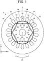
- FIG. 1 is a plan view schematically illustrating a structure of the electric motor 1 according to a first embodiment of the present invention.
- the electric motor 1 includes the rotor 2 and the stator 3.
- the electric motor 1 is, for example, a three-phase synchronous motor.
- the electric motor 1 is a permanent magnet synchronous motor (also called a brushless DC motor) such as a permanent magnet-embedded motor.
- the rotor 2 is rotatably disposed inside the stator 3.
- the air gap is formed between the rotor 2 and the stator 3.
- the air gap is, for example, from 0.3 mm to 1 mm.
- the rotor 2 rotates about an axis Ax.
- the rotor 2 includes a rotor core 21, at least one permanent magnet 22, and a shaft 24.
- the stator 3 is disposed outside the rotor 2.
- the stator 3 includes, for example, an annular stator core 31 and a stator winding wound around the stator core 31.
- the stator 3 includes a yoke 35 extending in the circumferential direction of the stator 3, and a plurality of teeth 34 extending radially from the yoke 35.
- the stator core 31 includes 18 teeth 34. Space between the teeth 34 is at least one slot 33 in which the stator winding is disposed.
- the stator winding used for the stator 3 is, for example, a winding in which an insulation film is formed around a conductor such as copper or aluminium.
- the stator winding forms a coil for generating a rotation magnetic field.
- a rotation magnetic field occurs.
- the number of windings and the diameter of the stator winding are set in accordance with, for example, a voltage applied to the stator winding, the rotation speed of the electric motor 1, or the cross-sectional area of the slot.
- the stator core 31 of the stator 3 is constituted by, for example, annular electromagnetic steel sheets stacked in the axial direction. Each of the electromagnetic steel sheets is punched in a predetermined shape beforehand.
- the thickness of each electromagnetic steel sheet of the stator 3 is, for example 0.1 mm to 0.7 mm. In this embodiment, the thickness of each electromagnetic steel sheet of the stator 3 is 0.35 mm.
- the electromagnetic steel sheets are fixed together by swaging.
- a structure of the rotor 2 will be described specifically.
- FIG. 2 is a plan view schematically illustrating the structure of the rotor 2.
- FIG. 3 is an enlarged view illustrating a region constituting one magnetic pole of the rotor 2.
- the rotor 2 includes the rotor core 21, a plurality of permanent magnets 22 embedded in the rotor core 21, and the shaft 24 fitted in a shaft hole 215 of the rotor core 21.
- the rotor 2 includes two or more magnetic poles.
- Two or more permanent magnets 22 constitute one magnetic pole of the rotor 2.
- the electric motor 2 is a permanent magnet-embedded electric rotor.
- the rotor core 21 is an annular rotor core.
- the rotor core 21 is formed of, for example, a plurality of electromagnetic steel sheets.
- the rotor core 21 includes at least one pair of magnet insertion holes 210, at least one center rib 213, and at least one thin portion 214.
- the rotor core 21 of the rotor 2 is constituted by, for example, annular electromagnetic steel sheets stacked in the axial direction. Each of the electromagnetic steel sheets is punched in a predetermined shape beforehand.
- the thickness of each electromagnetic steel sheet of the rotor 2 is, for example 0.1 mm to 0.7 mm. In this embodiment, the thickness of each electromagnetic steel sheet of the rotor 2 is 0.35 mm.
- the electromagnetic steel sheets are fixed together by swaging.
- the pair of magnet insertion holes 210 includes a first magnet insertion hole 211 and a second magnet insertion hole 212.
- the center of one pair of magnet insertion holes 210 projects toward the center (i.e., the axis Ax) of the rotor core 21. That is, one pair of magnet insertion holes 210 (i.e., the first magnet insertion hole 211 and the second magnet insertion hole 212) is disposed in a V shape in the xy plane.
- the center lib 213 is a part of the rotor core 21, and extends in the radial direction.
- the center lib 213 is disposed between the first magnet insertion hole 211 and the second magnet insertion hole 212.
- the center lib 213 is located at a magnetic pole center part of the rotor 2.
- arrangement of the pair of magnet insertion holes 210 is not limited to a V shape.
- the first magnet insertion hole 211 includes a magnet disposition part 211a (also referred to as a first magnet disposition part) in which the permanent magnet 22 as a first permanent magnet is disposed, a flux barrier part 211b (also referred to as a first flux barrier part) that is space communicating with the magnet disposition part 211a, an outside opening part 211c (also referred to as a first outside opening part), and an inside opening part 211d (also referred to as a first inside opening part).
- a magnet disposition part 211a also referred to as a first magnet disposition part
- a flux barrier part 211b also referred to as a first flux barrier part
- an outside opening part 211c also referred to as a first outside opening part
- an inside opening part 211d also referred to as a first inside opening part
- the second magnet insertion hole 212 includes a magnet disposition part 212a (also referred to as a second magnet disposition part) in which the permanent magnet 22 as a second permanent magnet is disposed, a flux barrier part 212b (also referred to as a second flux barrier part) that is space communicating with the magnet disposition part 212a, an outside opening part 212c (also referred to as a second outside opening part), and an inside opening part 212d (also referred to as a second inside opening part).
- a magnet disposition part 212a also referred to as a second magnet disposition part
- a flux barrier part 212b also referred to as a second flux barrier part
- an outside opening part 212c also referred to as a second outside opening part
- an inside opening part 212d also referred to as a second inside opening part
- the flux barrier part 211b is located at an inter-pole part of the rotor 2 or near the inter-pole part.
- the flux barrier part 212b is located at an inter-pole part of the rotor 2 or near the inter-pole part.
- the thin portion 214 between the outer peripheral surface of the rotor core 21 and the first magnet insertion hole 211 will be also referred to as a "first thin portion.”
- the thin portion 214 between the outer peripheral surface of the rotor core 21 and the second magnet insertion hole 212 will be also referred to as a "second thin portion.”
- the first thin portion is a region between the flux barrier part 211b and the outer peripheral surface of the rotor core 21, and the second thin portion is a region between the flux barrier part 212b and the outer peripheral surface of the rotor core 21.
- a minimum width of each thinner portion 214 in the radial direction is, for example, greater than or equal to the thickness of one electromagnetic steel sheet of the rotor core 21.
- the minimum width of each thinner portion 214 in the radial direction is preferably substantially equal to the thickness of one electromagnetic steel sheet of the rotor core 21. In this case, an increase of leakage flux in each thin portion 214 can be effectively suppressed.
- the rotor core 21 includes six magnet insertion holes 210, six center ribs 213, and twelve thin portions 214, and the shaft hole 215.
- the six magnet insertion holes 210 are arranged in the circumferential direction of the rotor 2.
- Each first magnet insertion hole 211 and each second magnet insertion hole 212 extend in the axial direction.
- the permanent magnet 22 as the first permanent magnet is placed in each first magnet insertion hole 211.
- the permanent magnet 22 as the second permanent magnet is placed in each second magnet insertion hole 212.
- the shaft 24 is fixed to the shaft hole 215 by a technique such as shrink fitting or press fitting.
- a technique such as shrink fitting or press fitting.
- Each permanent magnet 22 is, for example, a flat-plate permanent magnet.
- Each permanent magnet 22 is, for example, a rare earth magnet containing neodymium (Nd) and dysprosium (Dy).
- the rare earth magnet has a high residual flux density and a high coercive force.
- efficiency of the electric motor 1 can be enhanced.
- magnets except for rare earth magnets, such as ferrite sintered magnets may be used.
- Each permanent magnet 22 is magnetized in a direction perpendicular to the longitudinal direction of the permanent magnet 22 in the xy plane. That is, each permanent magnet 22 is magnetized in the lateral direction of the permanent magnet 22 in the xy plane.
- each permanent magnet 22 is W1 mm long in the longitudinal direction.
- the length of W1 is a maximum length of each permanent magnet 22 in the longitudinal direction. It should be noted that the length of each permanent magnet 22 in the longitudinal direction in the first magnet insertion hole 211 may be different from the length of each permanent magnet 22 in the longitudinal direction in the second magnet insertion hole 212.
- One pair of magnet insertion holes 210 is associated with one magnetic pole of the rotor 2.
- two permanent magnets 22 i.e., the first permanent magnet and the second permanent magnet placed in one pair of magnet insertion holes 210 constitute one magnetic pole (i.e., a north pole or a south pole) of the rotor 2.
- the number of magnetic poles of the rotor 2 only needs to two or more. In this embodiment, the rotor 2 has six magnetic poles.
- Each of the magnetic poles refers to a region serving as a north pole or a south pole of the rotor 2.
- a centrifugal force is exerted on a rotor core.
- the rotor core does not include a center lib, large stress is applied to thin portions between the outer peripheral surface of the rotor core and magnet insertion holes (specifically, flux barrier parts). If this stress is large, the rotor core (especially, the thin portions) is easily deformed.
- the rotor core 21 since the rotor core 21 includes the center ribs 213, part of the stress generated in the rotor 2 is dispersed to the center ribs 213, and thus stress applied to the thin portions 214 is alleviated. Accordingly, deformation of the rotor core 21, especially the thin portions 214, can be prevented. As a result, the electric motor 1 can rotate at high speed and consequently power of the electric motor 1 can be enhanced.
- FIGS. 4 and 5 are enlarged views each illustrating a peripheral structure of the center lib 213.
- the first magnet insertion hole 211 includes the magnet disposition part 211a, the flux barrier part 211b ( FIG. 3 ), the outside opening part 211c, and the inside opening part 211d.
- the second magnet insertion hole 212 includes the magnet disposition part 212a, the flux barrier part 212b ( FIG. 3 ), the outside opening part 212c, and the inside opening part 2121d.
- the outside opening part 211c is located on an outer side of the magnet disposition part 211a in the radial direction of the rotor core 21, and adjacent to the center lib 213.
- the outside opening part 211c has a radius of curvature of R1 in the xy plane.
- the outside opening part 211c projects from the magnet disposition part 211a outward in the radial direction.
- the inside opening part 211d is located on an inner side of the magnet disposition part 211a in the radial direction of the rotor core 21, and adjacent to the center lib 213.
- the inside opening part 211d has a radius of curvature of R2 in the xy plane.
- the inside opening part 211d projects from the magnet disposition part 211a inward in the radial direction.
- the rotor core 21 includes the outside opening part 211c and the inside opening part 211d, demagnetization of the permanent magnets 22 (especially, the permanent magnets 22 in the first magnet insertion holes 211) generated by a magnetic field from the stator winding of the stator 3 can be reduced. As a result, power of the electric motor 1 can be enhanced.
- the outside opening part 212c is located on an outer side of the magnet disposition part 212a in the radial direction of the rotor core 21, and adjacent to the center lib 213.
- the outside opening part 212c has a radius of curvature of R1 in the xy plane.
- the outside opening part 212c projects from the magnet disposition part 212a outward in the radial direction.
- the inside opening part 212d is located on an inner side of the magnet disposition part 212a in the radial direction of the rotor core 21, and adjacent to the center lib 213.
- the inside opening part 212d has a radius of curvature of R2 in the xy plane.
- the inside opening part 212d projects from the magnet disposition part 212a inward in the radial direction.
- the rotor core 21 includes the outside opening part 212c and the inside opening part 212d, demagnetization of the permanent magnets 22 (especially, the permanent magnets 22 in the second magnet insertion holes 212) generated by a magnetic field from the stator winding of the stator 3 can be reduced. As a result, power of the electric motor 1 can be enhanced.
- the radius of curvature of R1 is 0.5 mm
- the radius of curvature of R2 is 0.3 mm
- the length of W1 of each permanent magnet 22 is 21.5 mm.
- the radius of curvature of R1, the radius of curvature of R2, and the length of W1 of each permanent magnet 22 are not limited to these examples.
- the shape of the first magnet insertion hole 211 may be different from the shape of the second magnet insertion hole 212.
- the rotor core 21 includes, at each magnetic pole, an outside curved part 216a (also referred to as a first outside curved part), an outside curved part 216b (also referred to as a second outside curved part), an inside curved part 217a (also referred to as a first inside curved part), an inside curved part 217b (also referred to as a second inside curved part), an outside support part 218a (also referred to as a first outside support part), an outside support part 218b (also referred to as a second outside support part), an inside support part 219a (also referred to as a first inside support part), an inside support part 219b (also referred to as a second inside support part), an outside connection part 220a (also referred to as a first outside connection part), an outside connection part 220b (also referred to as a second outside connection part), an inside connection part 221a (also referred to as a first inside connection part), and an inside connection part 2
- the outside curved part 216a defines the outside opening part 211c.
- the outside curved part 216a has a curvature of 1/R1 in the xy plane. Accordingly, the outside opening part 211c has a radius of curvature of R1 in the xy plane.
- the outside curved part 216b defines the outside opening part 212c.
- the outside curved part 216b has a curvature of 1/R1 in the xy plane. Accordingly, the outside opening part 212c has a radius of curvature of R1 in the xy plane.
- the inside curved part 217a defines the inside opening part 211d.
- the inside curved part 217a has a curvature of 1/R2 in the xy plane. Accordingly, the inside opening part 211d has a radius of curvature of R2 in the xy plane.
- the inside curved part 217b defines the inside opening part 212d.
- the inside curved part 217b has a curvature of 1/R2 in the xy plane. Accordingly, the inside opening part 212d has a radius of curvature of R2 in the xy plane.
- the outside support part 218a supports the permanent magnet 22 in the first magnet insertion hole 211.
- the outside support part 218a defines the magnet disposition part 211a.
- the outside support part 218b supports the permanent magnet 22 in the second magnet insertion hole 212.
- the outside support part 218b defines the magnet disposition part 212a.
- the inside support part 219a supports the permanent magnet 22 in the first magnet insertion hole 211.
- the inside support part 219a defines the magnet disposition part 211a.
- the inside support part 219b supports the permanent magnet 22 in the second magnet insertion hole 212.
- the inside support part 219b defines the magnet disposition part 212a.
- the outside connection part 220a is located between the outside curved part 216a and the outside support part 218a, and connects the outside curved part 216a and the outside support part 218a.
- the outside connection part 220a has a radius of curvature of R3 in the xy plane. In other words, the outside connection part 220a has a curvature of 1/R3 in the xy plane.
- the outside connection part 220b is located between the outside curved part 216b and the outside support part 218b, and connects the outside curved part 216b and the outside support part 218b.
- the outside connection part 220b has a radius of curvature of R3 in the xy plane. In other words, the outside connection part 220b has a curvature of 1/R3 in the xy plane.
- the inside connection part 221a is located between the inside curved part 217a and the inside support part 219a, and connects the inside curved part 217a and the inside support part 219a.
- the inside connection part 221a has a radius of curvature of R4 in the xy plane. In other words, the inside connection part 221a has a curvature of 1/R4 in the xy plane.
- the inside connection part 221b is located between the inside curved part 217b and the inside support part 219b, and connects the inside curved part 217b and the inside support part 219b.
- the inside connection part 221b has a radius of curvature of R4 in the xy plane. In other words, the inside connection part 221b has a curvature of 1/R4 in the xy plane.
- magnetic resistance in the inside opening part 211d and the inside opening part 212d is smaller than that in the outside opening part 211c and the outside opening part 212c, and thus a magnetic force of each permanent magnet 22 can be effectively used. That is, if the rotor 2 satisfies R1 > R2, demagnetization of the permanent magnets 22 can be reduced, and power of the electric motor 1 can be enhanced.
- the relationship between the radii of curvature of R3 and R4 satisfies R3 > R4. Accordingly, it is possible to achieve both reduction of demagnetization of the permanent magnets 22 and increase in power of the electric motor 1.
- R3 increases, the lengths of the outside support part 218a and the outside support part 218b decrease. Accordingly, the outside opening part 211c and the outside opening part 212c become larger, and magnetic resistance increases. As a result, demagnetization in each permanent magnet 22 can be reduced.
- the radius of curvature of R4 decreases, the lengths of the inside support part 219a and the inside support part 219b increase.
- the inside opening part 211d and the inside opening part 212d become smaller, and thus a magnetic force of each permanent magnet 22 can be effectively used. As a result, it is possible to achieve both reduction of demagnetization of the permanent magnets 22 and increase in power of the electric motor 1.
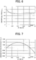
- FIG. 6 is a graph showing a relationship between a centrifugal force [p.u.] generated during rotation of the rotor 2 and a ratio between radii of curvature (specifically, a ratio of radius of curvature of R1 + R2 to the length of W1 of each permanent magnet).
- the rotor 2 preferably satisfies 0 ⁇ (R1 + R2)/W1 ⁇ 0.082. Accordingly, a centrifugal force generated during rotation of the rotor 2 can be reduced, and deformation of the rotor core 21, especially the thin portions 214, can be prevented.
- the rotor 2 more preferably satisfies 0.02 ⁇ (R1 + R2)/W1 ⁇ 0.082. Accordingly, a centrifugal force generated during rotation of the rotor 2 can be effectively reduced, and deformation of the rotor core 21, especially the thin portions 214, can be effectively prevented.
- FIG. 7 is a graph showing a relationship between a demagnetization resistance [p.u.] and a ratio between radii of curvature (specifically, a ratio of radii of curvature of R1 + R2 to the length of W1 of each permanent magnet).
- the demagnetization resistance refers to the magnitude of a current flowing in the stator winding of the stator 3 when the amount of magnetic flux from the permanent magnets 22 decreases by 1%. That is, in FIG. 7 , as the demagnetization resistance increases, the value of current flowing in the stator winding of the stator 3 can be increased. Accordingly, as the demagnetization resistance increases, power of the electric motor 1 can be enhanced.
- the rotor 2 preferably satisfies 0 ⁇ (R1 + R2)/W1 ⁇ 0.082. As a result, demagnetization resistance increases, and power of the electric motor 1 can be enhanced.
- the rotor 2 more preferably satisfies 0.02 ⁇ (R1 + R2)/W1 ⁇ 0.06. As a result, demagnetization resistance further increases, and power of the electric motor 1 can be enhanced.
- FIG. 8 is a graph showing a relationship between a demagnetization resistance [p.u.] and a ratio R3/R4 of a radius of curvature.
- the rotor 2 preferably satisfies 0 ⁇ R3/R4 ⁇ 4.45. As a result, demagnetization resistance increases, and power of the electric motor 1 can be enhanced.
- the rotor 2 more preferably satisfies 0 ⁇ R3/R4 ⁇ 4. As a result, demagnetization resistance further increases, and power of the electric motor 1 can be enhanced.
- the radii of curvature of R3 and R4 may be the same.
- FIG. 9 is an enlarged view illustrating a peripheral structure of the outside opening part 211c.
- the radius of curvature of R3 may be larger than the radius of curvature of R1.
- the outside support part 218a and the outside support part 218b become shorter. Accordingly, the outside opening part 211c and the outside opening part 212c become larger, and magnetic resistance increases. As a result, demagnetization in each permanent magnet 22 decreases, and power of the electric motor 1 can be further enhanced.
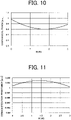
- FIG. 10 is a graph showing a relationship between a centrifugal force [p.u.] and a ratio of R1/R3 of a radius of curvature.
- the rotor 2 preferably satisfies 0 ⁇ R1/R3 ⁇ 3. Accordingly, a centrifugal force generated during rotation of the rotor 2 can be reduced, and deformation of the rotor core 21, especially the thin portions 214, can be prevented.
- FIG. 11 is a graph showing a relationship between a demagnetization resistance [p.u.] and a ratio of R1/R3 of a radius of curvature.
- the rotor 2 preferably satisfies 0 ⁇ R1/R3 ⁇ 3. As a result, demagnetization resistance increases, and power of the electric motor 1 can be enhanced.
- the rotor 2 more preferably satisfies 0.5 ⁇ R1/R3 ⁇ 3. Accordingly, a centrifugal force generated during rotation of the rotor 2 can be further reduced, and deformation of the rotor core 21, especially the thin portions 214, can be further prevented.
- the radius of curvature of R1 is, for example, 0.5 mm
- the radius of curvature of R3 is, for example, 0.6 mm
- the rotor 2 satisfies 0 ⁇ R1/R3 ⁇ 3.
- a compressor 300 according to a second embodiment of the present invention will be described.
- FIG. 12 is a cross-sectional view schematically illustrating a structure of the compressor 300.
- the compressor 300 includes an electric motor 1 serving as an electric element, a closed container 307 serving as a housing, and a compression mechanism 305 serving as a compression element (also referred to as a compression device).
- the compressor 300 is a scroll compressor. It should be noted that the compressor 300 is not limited to a scroll compressor.
- the compressor 300 may be a compressor other than the scroll compressor, for example, may be a rotary compressor.
- the electric motor 1 in the compressor 300 is the electric motor 1 described in the first embodiment.
- the electric motor 1 drives the compression mechanism 305.
- the compressor 300 also includes a subframe 308 supporting a lower end (i.e., an end opposite to the compression mechanism 305) of the shaft 24.
- the compression mechanism 305 is disposed inside the closed container 307.
- the compressor mechanism 305 includes a fixed scroll 301 having a spiral portion, a swing scroll 302 having a spiral portion forming a compression chamber between the spiral portion of the swing scroll 302 and the spiral portion of the fixed scroll 301, a compliance frame 303 holding the upper end of the shaft 24, and a guide frame 304 fixed to the closed container 307 and holding the compliance frame 303.
- a suction pipe 310 penetrating the closed container 307 is press fitted in the fixed scroll 301.
- the closed container 307 is provided with a discharge pipe 306 that discharges a high-pressure refrigerant gas discharged from the fixed scroll 301, to the outside.
- the discharge pipe 306 communicates with an opening disposed between the compressor mechanism 305 of the closed container 307 and the electric motor 1.
- the electric motor 1 is fixed to the closed container 307 by fitting the stator 3 in the closed container 307. A configuration of the electric motor 1 has been described above.
- a glass terminal 309 for supplying electric power to the electric motor 1 is fixed by welding.
- the compressor 300 includes the electric motor 1 described in the first embodiment, and thus, obtains advantages described in the first embodiment.
- the efficient compressor 300 can be provided.
- a refrigerating and air conditioning apparatus 7 serving as an air conditioner and including a compressor 300 according to a third embodiment will be described.
- FIG. 13 is a diagram schematically illustrating a configuration of the refrigerating air conditioning device 7 according to the third embodiment.
- the refrigerating and air conditioning apparatus 7 is capable of performing cooling and heating operations, for example.
- a refrigerant circuit diagram illustrated in FIG. 31 is an example of a refrigerant circuit diagram of an air conditioner capable of performing a cooling operation.
- the refrigerating and air conditioning apparatus 7 includes an outdoor unit 71, an indoor unit 72, and a refrigerant pipe 73 connecting the outdoor unit 71 and the indoor unit 72.
- the outdoor unit 71 includes a compressor 300, a condenser 74 as a heat exchanger, a throttling device 75, and an outdoor air blower 76 (first air blower).
- the condenser 74 condenses a refrigerant compressed by the compressor 300.
- the throttling device 75 decompresses the refrigerant condensed by the condenser 74 to thereby adjust a flow rate of the refrigerant.
- the throttling device 75 will be also referred to as a decompression device.
- the indoor unit 72 includes an evaporator 77 as a heat exchanger, and an indoor air blower 78 (second air blower).
- the evaporator 77 evaporates the refrigerant decompressed by the throttling device 75 to thereby cool indoor air.
- a refrigerant is compressed by the compressor 300 and the compressed refrigerant flows into the condenser 74.
- the condenser 74 condenses the refrigerant, and the condensed refrigerant flows into the throttling device 75.
- the throttling device 75 decompresses the refrigerant, and the decompressed refrigerant flows into the evaporator 77.
- the refrigerant evaporates, and the refrigerant (specifically a refrigerant gas) flows into the compressor 300 of the outdoor unit 71 again.
- the refrigerating and air conditioning apparatus 7 according to the third embodiment has the advantages described in the first and second embodiments.
- the refrigerating and air conditioning apparatus 7 according to the third embodiment includes the compressor 300 according to the second embodiment.
- the refrigerating and air conditioning apparatus 7 has high efficiency.
- 1 electric motor, 2 rotor, 3 stator, 7 refrigerating and air conditioning apparatus 21 rotor core, 22 permanent magnet, 71 outdoor unit, 72 indoor unit, 211 first magnet insertion hole, 211a magnet disposition part (first magnet disposition part), 211b flux barrier part (first flux barrier part), 211c outside opening part (first outside opening part), 211d inside opening part (first inside opening part), 212 second magnet insertion hole, 212a magnet disposition part (second magnet disposition part), 212b flux barrier part (second flux barrier part), 212c outside opening part (second outside opening part), 212d inside opening part (second inside opening part), 213 center lib, 300 compressor, 305 compression mechanism, 307 closed container, 74 condenser, 77 evaporator.
Landscapes
- Engineering & Computer Science (AREA)
- Power Engineering (AREA)
- Physics & Mathematics (AREA)
- Mechanical Engineering (AREA)
- Thermal Sciences (AREA)
- General Engineering & Computer Science (AREA)
- Permanent Field Magnets Of Synchronous Machinery (AREA)
- Iron Core Of Rotating Electric Machines (AREA)
- Applications Or Details Of Rotary Compressors (AREA)
- Compressor (AREA)
Abstract
Description
- The present invention relates to a rotor for use in an electric motor.
- Rotors having magnet insertion holes provided with flux barrier parts (also referred to as "flux barriers"), which are space, have been used. In such a rotor, leakage flux can be reduced, and thus motor efficiency can be enhanced. However, because of the presence of thin portions between the outer peripheral surface of the rotor and the flux barrier parts, stress tends to be concentrated on these thin portions during rotation of the rotor. As the rotation speed of the rotor increases, this stress increases, and as a result, the rotor, especially the thin portions, is easily deformed. In view of this, a rotor having a center rib (also simply referred to as a "rib") between two magnet insertion holes is proposed (see, for example, Patent Reference 1). In the rotor having the center rib, a part of stress occurring in the rotor is dispersed to the center rib, and thus stress generated on the thin portions is reduced. Accordingly, deformation of the rotor can be prevented.
- Patent Reference 1:
Japanese Patent Application Publication No. 2017-192211 - With a conventional technique, however, in the case where the center rib is present between two magnet insertion holes, the strength of the rotor to a centrifugal force increases, but magnetic flux passing through the center rib, that is, leakage flux, increases, and power of an electric motor decreases, disadvantageously.
- An object of the present invention is to enhance power of an electric motor.
- A rotor according to an aspect of the present invention includes: a rotor core including a first magnet insertion hole, a second magnet insertion hole, and a center lib between the first magnet insertion hole and the second magnet insertion hole;
- a first permanent magnet disposed in the first magnet insertion hole, the first permanent magnet being W1 mm long in a longitudinal direction in a plane perpendicular to an axial direction; and
- a second permanent magnet disposed in the second magnet insertion hole, the second permanent magnet being W1 mm long in a longitudinal direction in the plane, wherein
- the first magnet insertion hole includes
- a first magnet disposition part in which the first permanent magnet is disposed,
- a first flux barrier part communicating with the first magnet disposition part,
- a first outside opening part located on an outer side with respect to the first magnet disposition part in a radial direction of the rotor core, the first outside opening part having a radius of curvature of R1 mm in the plane, and
- a first inside opening part located on an inner side with respect to the first magnet disposition part in the radial direction, the first inside opening part having a radius of curvature of R2 mm in the plane, and
- the second magnet insertion hole includes
- a second magnet disposition part in which the second permanent magnet is disposed,
- a second flux barrier part communicating with the second magnet disposition part,
- a second outside opening part located on an outer side with respect to the second magnet disposition part in the radial direction, the second outside opening part having a radius of curvature of R1 mm in the plane, and
- a second inside opening part located on an inner side with respect to the second magnet disposition part in the radial direction, the second inside opening part having a radius of curvature of R2 mm in the plane, and
- the rotor satisfies R1 > R2 and 0 < (R1 + R2)/W1 < 0.082.
- An electric motor according to another aspect of the present invention includes:
- a stator; and
- the rotor disposed inside the stator.
- A compressor according to yet another aspect of the present invention includes:
- a closed container;
- a compression device disposed inside the closed container; and
- the electric motor to drive the compression device.
- An air conditioner according to still another aspect includes:
- the compressor; and
- a heat exchanger.
- According to the present invention, power of the electric motor can be enhanced.
-
-
FIG. 1 is a plan view schematically illustrating a structure of an electric motor according to a first embodiment of the present invention. -
FIG. 2 is a plan view schematically illustrating a structure of a rotor. -
FIG. 3 is an enlarged view illustrating a region constituting one magnetic pole of the rotor. -
FIG. 4 is an enlarged view illustrating a peripheral structure of a center lib. -
FIG. 5 is an enlarged view illustrating the peripheral structure of the center lib. -
FIG. 6 is a graph showing a relationship between a centrifugal force [p.u.] generated during rotation of the rotor and a ratio of radii of curvature. -
FIG. 7 is a graph showing a relationship between demagnetization resistance [p.u.] and a ratio of radii of curvature. -
FIG. 8 is a graph showing a relationship between demagnetization resistance [p.u.] and a ratio of radii of curvature. -
FIG. 9 is an enlarged view illustrating a peripheral structure of an outside opening part. -
FIG. 10 is a graph showing a relationship between a centrifugal force [p.u.] and a ratio of radii of curvature. -
FIG. 11 is a graph showing a relationship between a demagnetization resistance [p.u.] and a ratio of radii of curvature. -
FIG. 12 is a cross-sectional view schematically illustrating a structure of a compressor according to a second embodiment of the present invention. -
FIG. 13 is a diagram schematically illustrating a configuration of a refrigerating and air conditioning apparatus according to a third embodiment of the present invention. - In an xyz orthogonal coordinate system shown in each drawing, a z-axis direction (z axis) represents a direction parallel to an axis Ax of an
electric motor 1, an x-axis direction (x axis) represents a direction orthogonal to the z-axis direction (z axis), and a y-axis direction (y axis) represents a direction orthogonal to both the z-axis direction and the x-axis direction. The axis Ax is a center of astator 3, and is also a rotation center of arotor 2. A direction parallel to the axis Ax is also referred to as an "axial direction of theelectric motor 1," an "axial direction of therotor 2," or simply as an "axial direction." The "radial direction" is a radial direction of therotor 2 or thestator 3, and is a direction orthogonal to the axis Ax. An xy plane is a plane perpendicular to the axial direction. An arrow D1 represents a circumferential direction about the axis Ax. The circumferential direction of therotor 2 or thestator 3 will be also simply referred to as a "circumferential direction." -
FIG. 1 is a plan view schematically illustrating a structure of theelectric motor 1 according to a first embodiment of the present invention. - The
electric motor 1 includes therotor 2 and thestator 3. - In this embodiment, the
electric motor 1 is, for example, a three-phase synchronous motor. Specifically, theelectric motor 1 is a permanent magnet synchronous motor (also called a brushless DC motor) such as a permanent magnet-embedded motor. - The
rotor 2 is rotatably disposed inside thestator 3. - An air gap is formed between the
rotor 2 and thestator 3. The air gap is, for example, from 0.3 mm to 1 mm. Therotor 2 rotates about an axis Ax. Therotor 2 includes arotor core 21, at least onepermanent magnet 22, and ashaft 24. - The
stator 3 is disposed outside therotor 2. Thestator 3 includes, for example, anannular stator core 31 and a stator winding wound around thestator core 31. In the example illustrated inFIG. 1 , thestator 3 includes ayoke 35 extending in the circumferential direction of thestator 3, and a plurality ofteeth 34 extending radially from theyoke 35. In the example illustrated inFIG. 1 , thestator core 31 includes 18teeth 34. Space between theteeth 34 is at least oneslot 33 in which the stator winding is disposed. - The stator winding used for the
stator 3 is, for example, a winding in which an insulation film is formed around a conductor such as copper or aluminium. The stator winding forms a coil for generating a rotation magnetic field. When a current flows in the stator winding, a rotation magnetic field occurs. The number of windings and the diameter of the stator winding are set in accordance with, for example, a voltage applied to the stator winding, the rotation speed of theelectric motor 1, or the cross-sectional area of the slot. - The
stator core 31 of thestator 3 is constituted by, for example, annular electromagnetic steel sheets stacked in the axial direction. Each of the electromagnetic steel sheets is punched in a predetermined shape beforehand. The thickness of each electromagnetic steel sheet of thestator 3 is, for example 0.1 mm to 0.7 mm. In this embodiment, the thickness of each electromagnetic steel sheet of thestator 3 is 0.35 mm. The electromagnetic steel sheets are fixed together by swaging. - A structure of the
rotor 2 will be described specifically. -
FIG. 2 is a plan view schematically illustrating the structure of therotor 2. -
FIG. 3 is an enlarged view illustrating a region constituting one magnetic pole of therotor 2. - In the example illustrated in
FIG. 2 , therotor 2 includes therotor core 21, a plurality ofpermanent magnets 22 embedded in therotor core 21, and theshaft 24 fitted in ashaft hole 215 of therotor core 21. Therotor 2 includes two or more magnetic poles. Two or morepermanent magnets 22 constitute one magnetic pole of therotor 2. In this embodiment, theelectric motor 2 is a permanent magnet-embedded electric rotor. - The
rotor core 21 is an annular rotor core. Therotor core 21 is formed of, for example, a plurality of electromagnetic steel sheets. Therotor core 21 includes at least one pair of magnet insertion holes 210, at least onecenter rib 213, and at least onethin portion 214. - The
rotor core 21 of therotor 2 is constituted by, for example, annular electromagnetic steel sheets stacked in the axial direction. Each of the electromagnetic steel sheets is punched in a predetermined shape beforehand. The thickness of each electromagnetic steel sheet of therotor 2 is, for example 0.1 mm to 0.7 mm. In this embodiment, the thickness of each electromagnetic steel sheet of therotor 2 is 0.35 mm. The electromagnetic steel sheets are fixed together by swaging. - The pair of magnet insertion holes 210 includes a first
magnet insertion hole 211 and a secondmagnet insertion hole 212. In the xy plane, the center of one pair of magnet insertion holes 210 projects toward the center (i.e., the axis Ax) of therotor core 21. That is, one pair of magnet insertion holes 210 (i.e., the firstmagnet insertion hole 211 and the second magnet insertion hole 212) is disposed in a V shape in the xy plane. - The
center lib 213 is a part of therotor core 21, and extends in the radial direction. Thecenter lib 213 is disposed between the firstmagnet insertion hole 211 and the secondmagnet insertion hole 212. Thus, thecenter lib 213 is located at a magnetic pole center part of therotor 2. - As long as the
rotor core 21 includes thecenter lib 213, arrangement of the pair of magnet insertion holes 210 (i.e., the firstmagnet insertion hole 211 and the second magnet insertion hole 212) is not limited to a V shape. - The first
magnet insertion hole 211 includes amagnet disposition part 211a (also referred to as a first magnet disposition part) in which thepermanent magnet 22 as a first permanent magnet is disposed, aflux barrier part 211b (also referred to as a first flux barrier part) that is space communicating with themagnet disposition part 211a, anoutside opening part 211c (also referred to as a first outside opening part), and aninside opening part 211d (also referred to as a first inside opening part). - The second
magnet insertion hole 212 includes amagnet disposition part 212a (also referred to as a second magnet disposition part) in which thepermanent magnet 22 as a second permanent magnet is disposed, aflux barrier part 212b (also referred to as a second flux barrier part) that is space communicating with themagnet disposition part 212a, anoutside opening part 212c (also referred to as a second outside opening part), and aninside opening part 212d (also referred to as a second inside opening part). - The
flux barrier part 211b is located at an inter-pole part of therotor 2 or near the inter-pole part. Similarly, theflux barrier part 212b is located at an inter-pole part of therotor 2 or near the inter-pole part. - The
thin portion 214 between the outer peripheral surface of therotor core 21 and the firstmagnet insertion hole 211 will be also referred to as a "first thin portion." Thethin portion 214 between the outer peripheral surface of therotor core 21 and the secondmagnet insertion hole 212 will be also referred to as a "second thin portion." In this case, the first thin portion is a region between theflux barrier part 211b and the outer peripheral surface of therotor core 21, and the second thin portion is a region between theflux barrier part 212b and the outer peripheral surface of therotor core 21. - A minimum width of each
thinner portion 214 in the radial direction is, for example, greater than or equal to the thickness of one electromagnetic steel sheet of therotor core 21. The minimum width of eachthinner portion 214 in the radial direction is preferably substantially equal to the thickness of one electromagnetic steel sheet of therotor core 21. In this case, an increase of leakage flux in eachthin portion 214 can be effectively suppressed. - In the example illustrated in
FIG. 2 , therotor core 21 includes six magnet insertion holes 210, sixcenter ribs 213, and twelvethin portions 214, and theshaft hole 215. The six magnet insertion holes 210 are arranged in the circumferential direction of therotor 2. Each firstmagnet insertion hole 211 and each secondmagnet insertion hole 212 extend in the axial direction. - The
permanent magnet 22 as the first permanent magnet is placed in each firstmagnet insertion hole 211. Thepermanent magnet 22 as the second permanent magnet is placed in each secondmagnet insertion hole 212. - The
shaft 24 is fixed to theshaft hole 215 by a technique such as shrink fitting or press fitting. When a current flows in the stator winding of thestator 3, the rotor 2 (specifically, the rotor core 21) rotates, and rotation energy of therotor core 21 is transferred to theshaft 24. - Each
permanent magnet 22 is, for example, a flat-plate permanent magnet. Eachpermanent magnet 22 is, for example, a rare earth magnet containing neodymium (Nd) and dysprosium (Dy). The rare earth magnet has a high residual flux density and a high coercive force. Thus, in the case of using rare earth magnets as thepermanent magnets 22, efficiency of theelectric motor 1 can be enhanced. As thepermanent magnets 22, magnets except for rare earth magnets, such as ferrite sintered magnets, may be used. - Each
permanent magnet 22 is magnetized in a direction perpendicular to the longitudinal direction of thepermanent magnet 22 in the xy plane. That is, eachpermanent magnet 22 is magnetized in the lateral direction of thepermanent magnet 22 in the xy plane. - In the xy plane, each
permanent magnet 22 is W1 mm long in the longitudinal direction. The length of W1 is a maximum length of eachpermanent magnet 22 in the longitudinal direction. It should be noted that the length of eachpermanent magnet 22 in the longitudinal direction in the firstmagnet insertion hole 211 may be different from the length of eachpermanent magnet 22 in the longitudinal direction in the secondmagnet insertion hole 212. - One pair of magnet insertion holes 210 is associated with one magnetic pole of the
rotor 2. Specifically, two permanent magnets 22 (i.e., the first permanent magnet and the second permanent magnet) placed in one pair of magnet insertion holes 210 constitute one magnetic pole (i.e., a north pole or a south pole) of therotor 2. The number of magnetic poles of therotor 2 only needs to two or more. In this embodiment, therotor 2 has six magnetic poles. - Each of the magnetic poles ("each magnetic pole" or "magnetic pole") refers to a region serving as a north pole or a south pole of the
rotor 2. - In general, while a rotor rotates, a centrifugal force is exerted on a rotor core. Thus, if the rotor core does not include a center lib, large stress is applied to thin portions between the outer peripheral surface of the rotor core and magnet insertion holes (specifically, flux barrier parts). If this stress is large, the rotor core (especially, the thin portions) is easily deformed. On the other hand, in this embodiment, since the
rotor core 21 includes thecenter ribs 213, part of the stress generated in therotor 2 is dispersed to thecenter ribs 213, and thus stress applied to thethin portions 214 is alleviated. Accordingly, deformation of therotor core 21, especially thethin portions 214, can be prevented. As a result, theelectric motor 1 can rotate at high speed and consequently power of theelectric motor 1 can be enhanced. -
FIGS. 4 and 5 are enlarged views each illustrating a peripheral structure of thecenter lib 213. - As illustrated in
FIG. 4 , the firstmagnet insertion hole 211 includes themagnet disposition part 211a, theflux barrier part 211b (FIG. 3 ), theoutside opening part 211c, and theinside opening part 211d. The secondmagnet insertion hole 212, includes themagnet disposition part 212a, theflux barrier part 212b (FIG. 3 ), theoutside opening part 212c, and the inside opening part 2121d. - The
outside opening part 211c is located on an outer side of themagnet disposition part 211a in the radial direction of therotor core 21, and adjacent to thecenter lib 213. Theoutside opening part 211c has a radius of curvature of R1 in the xy plane. Thus, theoutside opening part 211c projects from themagnet disposition part 211a outward in the radial direction. - The
inside opening part 211d is located on an inner side of themagnet disposition part 211a in the radial direction of therotor core 21, and adjacent to thecenter lib 213. Theinside opening part 211d has a radius of curvature of R2 in the xy plane. Thus, theinside opening part 211d projects from themagnet disposition part 211a inward in the radial direction. - Since the
rotor core 21 includes theoutside opening part 211c and theinside opening part 211d, demagnetization of the permanent magnets 22 (especially, thepermanent magnets 22 in the first magnet insertion holes 211) generated by a magnetic field from the stator winding of thestator 3 can be reduced. As a result, power of theelectric motor 1 can be enhanced. - The
outside opening part 212c is located on an outer side of themagnet disposition part 212a in the radial direction of therotor core 21, and adjacent to thecenter lib 213. Theoutside opening part 212c has a radius of curvature of R1 in the xy plane. Thus, theoutside opening part 212c projects from themagnet disposition part 212a outward in the radial direction. - The
inside opening part 212d is located on an inner side of themagnet disposition part 212a in the radial direction of therotor core 21, and adjacent to thecenter lib 213. Theinside opening part 212d has a radius of curvature of R2 in the xy plane. Thus, theinside opening part 212d projects from themagnet disposition part 212a inward in the radial direction. - Since the
rotor core 21 includes theoutside opening part 212c and theinside opening part 212d, demagnetization of the permanent magnets 22 (especially, thepermanent magnets 22 in the second magnet insertion holes 212) generated by a magnetic field from the stator winding of thestator 3 can be reduced. As a result, power of theelectric motor 1 can be enhanced. - In this embodiment, the radius of curvature of R1 is 0.5 mm, the radius of curvature of R2 is 0.3 mm, and the length of W1 of each
permanent magnet 22 is 21.5 mm. It should be noted that the radius of curvature of R1, the radius of curvature of R2, and the length of W1 of eachpermanent magnet 22 are not limited to these examples. The shape of the firstmagnet insertion hole 211 may be different from the shape of the secondmagnet insertion hole 212. - As illustrated in
FIG. 4 , therotor core 21 includes, at each magnetic pole, an outsidecurved part 216a (also referred to as a first outside curved part), an outsidecurved part 216b (also referred to as a second outside curved part), an insidecurved part 217a (also referred to as a first inside curved part), an insidecurved part 217b (also referred to as a second inside curved part), anoutside support part 218a (also referred to as a first outside support part), anoutside support part 218b (also referred to as a second outside support part), aninside support part 219a (also referred to as a first inside support part), aninside support part 219b (also referred to as a second inside support part), anoutside connection part 220a (also referred to as a first outside connection part), anoutside connection part 220b (also referred to as a second outside connection part), aninside connection part 221a (also referred to as a first inside connection part), and aninside connection part 221b (also referred to as a second inside connection part). - The outside
curved part 216a defines theoutside opening part 211c. The outsidecurved part 216a has a curvature of 1/R1 in the xy plane. Accordingly, theoutside opening part 211c has a radius of curvature of R1 in the xy plane. - The outside
curved part 216b defines theoutside opening part 212c. The outsidecurved part 216b has a curvature of 1/R1 in the xy plane. Accordingly, theoutside opening part 212c has a radius of curvature of R1 in the xy plane. - The inside
curved part 217a defines theinside opening part 211d. The insidecurved part 217a has a curvature of 1/R2 in the xy plane. Accordingly, theinside opening part 211d has a radius of curvature of R2 in the xy plane. - The inside
curved part 217b defines theinside opening part 212d. The insidecurved part 217b has a curvature of 1/R2 in the xy plane. Accordingly, theinside opening part 212d has a radius of curvature of R2 in the xy plane. - The
outside support part 218a supports thepermanent magnet 22 in the firstmagnet insertion hole 211. Theoutside support part 218a defines themagnet disposition part 211a. - The
outside support part 218b supports thepermanent magnet 22 in the secondmagnet insertion hole 212. Theoutside support part 218b defines themagnet disposition part 212a. - The
inside support part 219a supports thepermanent magnet 22 in the firstmagnet insertion hole 211. Theinside support part 219a defines themagnet disposition part 211a. - The
inside support part 219b supports thepermanent magnet 22 in the secondmagnet insertion hole 212. Theinside support part 219b defines themagnet disposition part 212a. - The
outside connection part 220a is located between the outsidecurved part 216a and theoutside support part 218a, and connects the outsidecurved part 216a and theoutside support part 218a. Theoutside connection part 220a has a radius of curvature of R3 in the xy plane. In other words, theoutside connection part 220a has a curvature of 1/R3 in the xy plane. - The
outside connection part 220b is located between the outsidecurved part 216b and theoutside support part 218b, and connects the outsidecurved part 216b and theoutside support part 218b. Theoutside connection part 220b has a radius of curvature of R3 in the xy plane. In other words, theoutside connection part 220b has a curvature of 1/R3 in the xy plane. - The
inside connection part 221a is located between the insidecurved part 217a and theinside support part 219a, and connects the insidecurved part 217a and theinside support part 219a. Theinside connection part 221a has a radius of curvature of R4 in the xy plane. In other words, theinside connection part 221a has a curvature of 1/R4 in the xy plane. - The
inside connection part 221b is located between the insidecurved part 217b and theinside support part 219b, and connects the insidecurved part 217b and theinside support part 219b. Theinside connection part 221b has a radius of curvature of R4 in the xy plane. In other words, theinside connection part 221b has a curvature of 1/R4 in the xy plane. - The relationship between the radii of curvature of R1 and R2 satisfies R1 > R2. Accordingly, stress concentrated on the
center libs 213 is dispersed, and thus, mechanical strength of therotor core 21 to a centrifugal force generated in therotor 2 can be increased, and deformation of therotor core 21, especially thethin portions 214, and be prevented. Consequently, theelectric motor 1 can rotate at high speed, and thus power of theelectric motor 1 can be enhanced. In addition, a magnetic resistance becomes large in theoutside opening part 211c and theoutside opening part 212c, and thus, demagnetization in eachpermanent magnet 22 can be reduced. On the other hand, magnetic resistance in theinside opening part 211d and theinside opening part 212d is smaller than that in theoutside opening part 211c and theoutside opening part 212c, and thus a magnetic force of eachpermanent magnet 22 can be effectively used. That is, if therotor 2 satisfies R1 > R2, demagnetization of thepermanent magnets 22 can be reduced, and power of theelectric motor 1 can be enhanced. - The relationship between the radii of curvature of R3 and R4 satisfies R3 > R4. Accordingly, it is possible to achieve both reduction of demagnetization of the
permanent magnets 22 and increase in power of theelectric motor 1. Specifically, as the radius of curvature of R3 increases, the lengths of theoutside support part 218a and theoutside support part 218b decrease. Accordingly, theoutside opening part 211c and theoutside opening part 212c become larger, and magnetic resistance increases. As a result, demagnetization in eachpermanent magnet 22 can be reduced. On the other hand, as the radius of curvature of R4 decreases, the lengths of theinside support part 219a and theinside support part 219b increase. Accordingly, theinside opening part 211d and theinside opening part 212d become smaller, and thus a magnetic force of eachpermanent magnet 22 can be effectively used. As a result, it is possible to achieve both reduction of demagnetization of thepermanent magnets 22 and increase in power of theelectric motor 1. -
FIG. 6 is a graph showing a relationship between a centrifugal force [p.u.] generated during rotation of therotor 2 and a ratio between radii of curvature (specifically, a ratio of radius of curvature of R1 + R2 to the length of W1 of each permanent magnet). - As shown in
FIG. 6 , therotor 2 preferably satisfies 0 < (R1 + R2)/W1 < 0.082. Accordingly, a centrifugal force generated during rotation of therotor 2 can be reduced, and deformation of therotor core 21, especially thethin portions 214, can be prevented. Therotor 2 more preferably satisfies 0.02 < (R1 + R2)/W1 < 0.082. Accordingly, a centrifugal force generated during rotation of therotor 2 can be effectively reduced, and deformation of therotor core 21, especially thethin portions 214, can be effectively prevented. -
FIG. 7 is a graph showing a relationship between a demagnetization resistance [p.u.] and a ratio between radii of curvature (specifically, a ratio of radii of curvature of R1 + R2 to the length of W1 of each permanent magnet). In this embodiment, the demagnetization resistance refers to the magnitude of a current flowing in the stator winding of thestator 3 when the amount of magnetic flux from thepermanent magnets 22 decreases by 1%. That is, inFIG. 7 , as the demagnetization resistance increases, the value of current flowing in the stator winding of thestator 3 can be increased. Accordingly, as the demagnetization resistance increases, power of theelectric motor 1 can be enhanced. - As shown in
FIG. 7 , therotor 2 preferably satisfies 0 < (R1 + R2)/W1 < 0.082. As a result, demagnetization resistance increases, and power of theelectric motor 1 can be enhanced. - As the proportion of the radii of curvature of R1 and R2 to the length of W1 of each
permanent magnet 22 increases, the area of thepermanent magnet 22 facing theoutside opening part 211c and the area of thepermanent magnet 22 facing theoutside opening part 212c increase. Accordingly, an effective amount of magnetic flux from eachpermanent magnet 22 decreases, and power of theelectric motor 1 decreases. On the other hand, as the proportion of the radii of curvature of R1 and R2 to the length of W1 of eachpermanent magnet 22 decreases, thepermanent magnets 22 are more easily demagnetized. Accordingly, therotor 2 more preferably satisfies 0.02 < (R1 + R2)/W1 < 0.06. As a result, demagnetization resistance further increases, and power of theelectric motor 1 can be enhanced. - In addition, if the
rotor 2 satisfies R1 > R2 and 0 < (R1 + R2)/W1 < 0.082, demagnetization of thepermanent magnets 22 can be further reduced, and power of theelectric motor 1 can be further enhanced. - If the
rotor 2 satisfies R1 > R2 and 0.02 < (R1 + R2)/W1 < 0.082, demagnetization of thepermanent magnets 22 can be further reduced, and power of theelectric motor 1 can be further enhanced. - If the
rotor 2 satisfies R1 > R2 and 0.02 < (R1 + R2)/W1 < 0.06, demagnetization of thepermanent magnets 22 can be further reduced, and power of theelectric motor 1 can be further enhanced. -
FIG. 8 is a graph showing a relationship between a demagnetization resistance [p.u.] and a ratio R3/R4 of a radius of curvature. - As shown in
FIG. 8 , therotor 2 preferably satisfies 0 < R3/R4 < 4.45. As a result, demagnetization resistance increases, and power of theelectric motor 1 can be enhanced. Therotor 2 more preferably satisfies 0 < R3/R4 < 4. As a result, demagnetization resistance further increases, and power of theelectric motor 1 can be enhanced. - The radii of curvature of R3 and R4 may be the same. In this case, the radii of curvature of R3 and R4 are, for example, 0.9 mm, and the
rotor 2 satisfies R3/R4 = 1. As a result, demagnetization resistance can be enhanced, as compared to a conventional rotor (i.e., R3 = R4 = 0). -
FIG. 9 is an enlarged view illustrating a peripheral structure of theoutside opening part 211c. - As illustrated in
FIG. 9 , the radius of curvature of R3 may be larger than the radius of curvature of R1. As the radius of curvature of R3 increases, theoutside support part 218a and theoutside support part 218b become shorter. Accordingly, theoutside opening part 211c and theoutside opening part 212c become larger, and magnetic resistance increases. As a result, demagnetization in eachpermanent magnet 22 decreases, and power of theelectric motor 1 can be further enhanced. -
FIG. 10 is a graph showing a relationship between a centrifugal force [p.u.] and a ratio of R1/R3 of a radius of curvature. - As shown in
FIG. 10 , therotor 2 preferably satisfies 0 < R1/R3 < 3. Accordingly, a centrifugal force generated during rotation of therotor 2 can be reduced, and deformation of therotor core 21, especially thethin portions 214, can be prevented. -
FIG. 11 is a graph showing a relationship between a demagnetization resistance [p.u.] and a ratio of R1/R3 of a radius of curvature. - As shown in
FIG. 11 , therotor 2 preferably satisfies 0 < R1/R3 < 3. As a result, demagnetization resistance increases, and power of theelectric motor 1 can be enhanced. - The
rotor 2 more preferably satisfies 0.5 < R1/R3 < 3. Accordingly, a centrifugal force generated during rotation of therotor 2 can be further reduced, and deformation of therotor core 21, especially thethin portions 214, can be further prevented. - In the examples shown in
FIGS. 10 and 11 , the radius of curvature of R1 is, for example, 0.5 mm, and the radius of curvature of R3 is, for example, 0.6 mm, and therotor 2 satisfies 0 < R1/R3 < 3. As a result, demagnetization resistance can be enhanced, as compared to a conventional rotor (i.e., R1 = R3 = 0). - A
compressor 300 according to a second embodiment of the present invention will be described. -
FIG. 12 is a cross-sectional view schematically illustrating a structure of thecompressor 300. - The
compressor 300 includes anelectric motor 1 serving as an electric element, aclosed container 307 serving as a housing, and acompression mechanism 305 serving as a compression element (also referred to as a compression device). In this embodiment, thecompressor 300 is a scroll compressor. It should be noted that thecompressor 300 is not limited to a scroll compressor. Thecompressor 300 may be a compressor other than the scroll compressor, for example, may be a rotary compressor. - The
electric motor 1 in thecompressor 300 is theelectric motor 1 described in the first embodiment. Theelectric motor 1 drives thecompression mechanism 305. - The
compressor 300 also includes asubframe 308 supporting a lower end (i.e., an end opposite to the compression mechanism 305) of theshaft 24. - The
compression mechanism 305 is disposed inside theclosed container 307. Thecompressor mechanism 305 includes a fixedscroll 301 having a spiral portion, aswing scroll 302 having a spiral portion forming a compression chamber between the spiral portion of theswing scroll 302 and the spiral portion of the fixedscroll 301, acompliance frame 303 holding the upper end of theshaft 24, and aguide frame 304 fixed to theclosed container 307 and holding thecompliance frame 303. - A
suction pipe 310 penetrating theclosed container 307 is press fitted in the fixedscroll 301. Theclosed container 307 is provided with adischarge pipe 306 that discharges a high-pressure refrigerant gas discharged from the fixedscroll 301, to the outside. Thedischarge pipe 306 communicates with an opening disposed between thecompressor mechanism 305 of theclosed container 307 and theelectric motor 1. - The
electric motor 1 is fixed to theclosed container 307 by fitting thestator 3 in theclosed container 307. A configuration of theelectric motor 1 has been described above. To theclosed container 307, aglass terminal 309 for supplying electric power to theelectric motor 1 is fixed by welding. - When a current flows in a stator winding 32 of the
electric motor 1, theelectric motor 1 is driven. When theelectric motor 2 rotates, this rotation is transferred to theswing scroll 302, and theswing scroll 302 swings. When theswing scroll 302 swings, the volume of the compression chamber formed by the spiral portion of theswing scroll 302 and the spiral portion of the fixedscroll 301 changes. Then, a refrigerant gas is sucked from thesuction pipe 310, compressed, and then discharged from thedischarge pipe 306. - The
compressor 300 includes theelectric motor 1 described in the first embodiment, and thus, obtains advantages described in the first embodiment. - In addition, since the
compressor 300 includes theelectric motor 1 described in the first embodiment, theefficient compressor 300 can be provided. - THIRD EMBODIMENT
- A refrigerating and
air conditioning apparatus 7 serving as an air conditioner and including acompressor 300 according to a third embodiment will be described. -
FIG. 13 is a diagram schematically illustrating a configuration of the refrigeratingair conditioning device 7 according to the third embodiment. - The refrigerating and
air conditioning apparatus 7 is capable of performing cooling and heating operations, for example. A refrigerant circuit diagram illustrated in FIG. 31 is an example of a refrigerant circuit diagram of an air conditioner capable of performing a cooling operation. - The refrigerating and
air conditioning apparatus 7 according to the third embodiment includes anoutdoor unit 71, anindoor unit 72, and arefrigerant pipe 73 connecting theoutdoor unit 71 and theindoor unit 72. - The
outdoor unit 71 includes acompressor 300, acondenser 74 as a heat exchanger, athrottling device 75, and an outdoor air blower 76 (first air blower). Thecondenser 74 condenses a refrigerant compressed by thecompressor 300. The throttlingdevice 75 decompresses the refrigerant condensed by thecondenser 74 to thereby adjust a flow rate of the refrigerant. The throttlingdevice 75 will be also referred to as a decompression device. - The
indoor unit 72 includes anevaporator 77 as a heat exchanger, and an indoor air blower 78 (second air blower). Theevaporator 77 evaporates the refrigerant decompressed by the throttlingdevice 75 to thereby cool indoor air. - A basic operation of a cooling operation in the refrigerating and
air conditioning apparatus 7 will now be described. In the cooling operation, a refrigerant is compressed by thecompressor 300 and the compressed refrigerant flows into thecondenser 74. Thecondenser 74 condenses the refrigerant, and the condensed refrigerant flows into thethrottling device 75. The throttlingdevice 75 decompresses the refrigerant, and the decompressed refrigerant flows into theevaporator 77. In theevaporator 77, the refrigerant evaporates, and the refrigerant (specifically a refrigerant gas) flows into thecompressor 300 of theoutdoor unit 71 again. When the air is sent to thecondenser 74 by theoutdoor air blower 76, heat moves between the refrigerant and the air, and similarly, when the air is sent to theevaporator 77 by theindoor air blower 78, heat is moved between the refrigerant and the air. - The configuration and operation of the refrigerating and
air conditioning apparatus 7 described above are examples, and the present invention is not limited to the examples described above. - The refrigerating and
air conditioning apparatus 7 according to the third embodiment has the advantages described in the first and second embodiments. - In addition, since the refrigerating and
air conditioning apparatus 7 according to the third embodiment includes thecompressor 300 according to the second embodiment. Thus, the refrigerating andair conditioning apparatus 7 has high efficiency. - Features of the embodiments and features of the variations described above can be combined as appropriate.
- 1 electric motor, 2 rotor, 3 stator, 7 refrigerating and air conditioning apparatus, 21 rotor core, 22 permanent magnet, 71 outdoor unit, 72 indoor unit, 211 first magnet insertion hole, 211a magnet disposition part (first magnet disposition part), 211b flux barrier part (first flux barrier part), 211c outside opening part (first outside opening part), 211d inside opening part (first inside opening part), 212 second magnet insertion hole, 212a magnet disposition part (second magnet disposition part), 212b flux barrier part (second flux barrier part), 212c outside opening part (second outside opening part), 212d inside opening part (second inside opening part), 213 center lib, 300 compressor, 305 compression mechanism, 307 closed container, 74 condenser, 77 evaporator.
Claims (9)
- A rotor comprising:a rotor core including a first magnet insertion hole, a second magnet insertion hole, and a center lib between the first magnet insertion hole and the second magnet insertion hole;a first permanent magnet disposed in the first magnet insertion hole, the first permanent magnet being W1 mm long in a longitudinal direction in a plane perpendicular to an axial direction; anda second permanent magnet disposed in the second magnet insertion hole, the second permanent magnet being W1 mm long in a longitudinal direction in the plane, whereinthe first magnet insertion hole includesa first magnet disposition part in which the first permanent magnet is disposed,a first flux barrier part communicating with the first magnet disposition part,a first outside opening part located on an outer side with respect to the first magnet disposition part in a radial direction of the rotor core, the first outside opening part having a radius of curvature of R1 mm in the plane, anda first inside opening part located on an inner side with respect to the first magnet disposition part in the radial direction, the first inside opening part having a radius of curvature of R2 mm in the plane, andthe second magnet insertion hole includesa second magnet disposition part in which the second permanent magnet is disposed,a second flux barrier part communicating with the second magnet disposition part,a second outside opening part located on an outer side with respect to the second magnet disposition part in the radial direction, the second outside opening part having a radius of curvature of R1 mm in the plane, anda second inside opening part located on an inner side with respect to the second magnet disposition part in the radial direction, the second inside opening part having a radius of curvature of R2 mm in the plane, andthe rotor satisfies R1 > R2 and 0 < (R1 + R2)/W1 < 0.082.
- The rotor according to claim 1, whereinthe rotor core includesa first outside curved part defining the first outside opening part,a first outside support part supporting the first permanent magnet,a first outside connection part connecting the first outside curved part and the first outside support part, the first outside connection part having a radius of curvature of R3 in the plane,a first inside curved part defining the first inside opening part,a first inside support part supporting the first permanent magnet,a first inside connection part connecting the first inside curved part and the first inside support part, the first inside connection part having a radius of curvature of R4 in the plane,a second outside curved part defining the second outside opening part,a second outside support part supporting the second permanent magnet,a second outside connection part connecting the second outside curved part and the second outside support part, the second outside connection part having a radius of curvature of R3 in the plane,a second inside curved part defining the second inside opening part,a second inside support part supporting the second permanent magnet, anda second inside connection part connecting the second inside curved part and the second inside support part, the second inside connection part having a radius of curvature of R4 in the plane, andthe rotor satisfies 0 < R3/R4 < 4.45.
- The rotor according to claim 2, wherein the rotor satisfies 0 < R3/R4 < 4.
- The rotor according to any one of claims 1 to 3, wherein the rotor satisfies 0 < R1/R3 < 3.
- The rotor according to any one of claims 1 to 4, wherein the rotor satisfies R1 > R2 and 0.02 < (R1 + R2)/W1 < 0.082.
- The rotor according to any one of claims 1 to 4, wherein the rotor satisfies R1 > R2 and 0.02 < (R1 + R2)/W1 < 0.06.
- An electric motor comprising:a stator; andthe rotor according to any one of claims 1 to 6, the rotor being disposed inside the stator.
- A compressor comprising:a closed container;a compression device disposed inside the closed container; andthe electric motor according to claim 7, to drive the compression device.
- An air conditioner comprising:the compressor according to claim 8; anda heat exchanger.
Applications Claiming Priority (1)
| Application Number | Priority Date | Filing Date | Title |
|---|---|---|---|
| PCT/JP2019/025334 WO2020261418A1 (en) | 2019-06-26 | 2019-06-26 | Rotor, electric motor, compressor, and air conditioner |
Publications (3)
| Publication Number | Publication Date |
|---|---|
| EP3993227A1 true EP3993227A1 (en) | 2022-05-04 |
| EP3993227A4 EP3993227A4 (en) | 2022-07-06 |
| EP3993227B1 EP3993227B1 (en) | 2024-10-30 |
Family
ID=74060804
Family Applications (1)
| Application Number | Title | Priority Date | Filing Date |
|---|---|---|---|
| EP19935152.9A Active EP3993227B1 (en) | 2019-06-26 | 2019-06-26 | Rotor, electric motor, compressor, and air conditioner |
Country Status (6)
| Country | Link |
|---|---|
| US (1) | US11962191B2 (en) |
| EP (1) | EP3993227B1 (en) |
| JP (1) | JP7258140B2 (en) |
| CN (1) | CN113994570B (en) |
| AU (2) | AU2019455656B2 (en) |
| WO (1) | WO2020261418A1 (en) |
Families Citing this family (1)
| Publication number | Priority date | Publication date | Assignee | Title |
|---|---|---|---|---|
| JP2023136439A (en) * | 2022-03-17 | 2023-09-29 | トヨタ自動車株式会社 | rotor |
Family Cites Families (20)
| Publication number | Priority date | Publication date | Assignee | Title |
|---|---|---|---|---|
| JPH09294344A (en) * | 1996-04-26 | 1997-11-11 | Meidensha Corp | Rotor of permanent magnet type rotating machine |
| JP2002281700A (en) * | 2001-03-23 | 2002-09-27 | Fuji Electric Co Ltd | Rotor of embedded magnet type rotating machine |
| JP5730736B2 (en) | 2011-10-04 | 2015-06-10 | 日立オートモティブシステムズ株式会社 | Permanent magnet type rotating electric machine and vehicle equipped with permanent magnet type rotating electric machine |
| JP5215486B1 (en) * | 2011-11-14 | 2013-06-19 | ファナック株式会社 | Permanent magnet synchronous motor rotor, motor and machine tool |
| EP2602911B1 (en) * | 2011-12-08 | 2018-09-26 | Danfoss Mobile Electrification Oy | Rotor with embedded permanent magnets for power transmission chain in a mobile working machine |
| JP5936060B2 (en) * | 2012-09-14 | 2016-06-15 | 株式会社デンソー | Rotating electrical machine rotor |
| WO2014068655A1 (en) * | 2012-10-30 | 2014-05-08 | 三菱電機株式会社 | Electric motor with embedded permanent magnet, and refrigeration and air conditioning equipment equipped with same |
| JP6018940B2 (en) * | 2013-01-31 | 2016-11-02 | マブチモーター株式会社 | Rotor and motor |
| CN105075079B (en) * | 2013-02-14 | 2017-07-21 | 三菱电机株式会社 | Permanent magnet embedded motors, compressors and refrigeration and air conditioning units |
| JP6191370B2 (en) * | 2013-10-03 | 2017-09-06 | シンフォニアテクノロジー株式会社 | Synchronous motor |
| WO2015087377A1 (en) * | 2013-12-09 | 2015-06-18 | 三菱電機株式会社 | Embedded-permanent-magnet electric motor |
| JP5930409B2 (en) * | 2013-12-11 | 2016-06-08 | 株式会社安川電機 | Rotating electric machine |
| JP6223568B2 (en) * | 2014-07-01 | 2017-11-01 | 三菱電機株式会社 | Permanent magnet embedded electric motor, compressor and refrigeration air conditioner |
| US10110077B2 (en) * | 2014-08-21 | 2018-10-23 | Mitsubishi Electric Corporation | Permanent-magnet-embedded electric motor and compressor |
| US20170338707A1 (en) | 2014-12-22 | 2017-11-23 | Mitsubishi Electric Corporation | Rotor for rotary electrical machine |
| JP2017028862A (en) | 2015-07-22 | 2017-02-02 | 三菱電機株式会社 | Rotor, rotating electrical machine, electric compressor and refrigeration air conditioner |
| JP6551685B2 (en) | 2016-04-13 | 2019-07-31 | 本田技研工業株式会社 | Rotor of electric rotating machine |
| JP2018164378A (en) * | 2017-03-27 | 2018-10-18 | 本田技研工業株式会社 | Magnet for IPM rotor, IPM rotor and method for manufacturing magnet for IPM rotor |
| DE102017003606A1 (en) * | 2017-04-13 | 2017-10-19 | Daimler Ag | Electrical sheet for a rotor of an electrical machine, in particular for a motor vehicle |
| JP6692501B2 (en) * | 2017-08-30 | 2020-05-13 | 三菱電機株式会社 | Rotor, electric motor, compressor and air conditioner |
-
2019
- 2019-06-26 WO PCT/JP2019/025334 patent/WO2020261418A1/en not_active Ceased
- 2019-06-26 JP JP2021528732A patent/JP7258140B2/en active Active
- 2019-06-26 EP EP19935152.9A patent/EP3993227B1/en active Active
- 2019-06-26 AU AU2019455656A patent/AU2019455656B2/en not_active Ceased
- 2019-06-26 CN CN201980097507.4A patent/CN113994570B/en not_active Expired - Fee Related
- 2019-06-26 US US17/613,779 patent/US11962191B2/en active Active
-
2023
- 2023-07-27 AU AU2023208167A patent/AU2023208167A1/en not_active Abandoned
Also Published As
| Publication number | Publication date |
|---|---|
| EP3993227B1 (en) | 2024-10-30 |
| JPWO2020261418A1 (en) | 2021-11-18 |
| AU2023208167A1 (en) | 2023-08-17 |
| AU2019455656B2 (en) | 2023-02-09 |
| EP3993227A4 (en) | 2022-07-06 |
| CN113994570B (en) | 2023-06-20 |
| CN113994570A (en) | 2022-01-28 |
| US20220231554A1 (en) | 2022-07-21 |
| AU2019455656A1 (en) | 2022-01-20 |
| JP7258140B2 (en) | 2023-04-14 |
| US11962191B2 (en) | 2024-04-16 |
| WO2020261418A1 (en) | 2020-12-30 |
Similar Documents
| Publication | Publication Date | Title |
|---|---|---|
| JP6692896B2 (en) | Electric motors, blowers, compressors and air conditioners | |
| CN111033947B (en) | Rotors, Electric Motors, Compressors and Air Conditioners | |
| US11962192B2 (en) | Electric motor, compressor, and air conditioner | |
| US11996740B2 (en) | Rotor, electric motor, compressor, and air conditioner | |
| CN116111757A (en) | Motors, compressors, blowers, and refrigeration and air conditioning units | |
| CN112075011A (en) | Rotor, motor, compressor, and air conditioner | |
| JPWO2020213081A1 (en) | Rotors, motors, compressors, and air conditioners | |
| AU2023208167A1 (en) | Rotor, electric motor, compressor, and air conditioner | |
| JP7154373B2 (en) | Electric motors, compressors, and air conditioners | |
| US20220286004A1 (en) | Rotor, motor, compressor, and air conditioner | |
| US11973373B2 (en) | Rotor, motor, compressor, and refrigeration and air-conditioning device | |
| CN109417320B (en) | Rotor, motor, blower, compressor, and air conditioner | |
| US20240030791A1 (en) | Magnetizing apparatus, magnetizing method, rotor, motor, compressor, and refrigeration cycle apparatus | |
| WO2023032134A1 (en) | Electric motor, compressor, and refrigeration cycle device | |
| US11916438B2 (en) | Magnetization ring, magnetization method, magnetization apparatus, rotor, motor, compressor, and air conditioner | |
| US20230291263A1 (en) | Stator, electric motor, compressor, air conditioner, and method for fabricating stator | |
| CN115398778A (en) | Rotor, motor, compressor, air conditioner, and method for manufacturing rotor | |
| WO2020059056A1 (en) | Stator, motor, compressor and air conditioning device | |
| JPWO2020026431A1 (en) | Stator, motor, compressor, and refrigeration air conditioner | |
| US20240154504A1 (en) | Motor, compressor, refrigeration cycle apparatus, magnetizing method, and magnetizing apparatus | |
| US20240348115A1 (en) | Rotor, motor, compressor, and refrigeration cycle apparatus | |
| WO2024150393A1 (en) | Magnetization method, electric motor, compressor, and refrigeration cycle apparatus | |
| CN118160191A (en) | Rotors, motors, compressors and air conditioning devices |
Legal Events
| Date | Code | Title | Description |
|---|---|---|---|
| STAA | Information on the status of an ep patent application or granted ep patent |
Free format text: STATUS: THE INTERNATIONAL PUBLICATION HAS BEEN MADE |
|
| PUAI | Public reference made under article 153(3) epc to a published international application that has entered the european phase |
Free format text: ORIGINAL CODE: 0009012 |
|
| STAA | Information on the status of an ep patent application or granted ep patent |
Free format text: STATUS: REQUEST FOR EXAMINATION WAS MADE |
|
| 17P | Request for examination filed |
Effective date: 20211216 |
|
| AK | Designated contracting states |
Kind code of ref document: A1 Designated state(s): AL AT BE BG CH CY CZ DE DK EE ES FI FR GB GR HR HU IE IS IT LI LT LU LV MC MK MT NL NO PL PT RO RS SE SI SK SM TR |
|
| A4 | Supplementary search report drawn up and despatched |
Effective date: 20220607 |
|
| RIC1 | Information provided on ipc code assigned before grant |
Ipc: H02K 29/03 20060101ALN20220601BHEP Ipc: H02K 1/276 20220101AFI20220601BHEP |
|
| DAV | Request for validation of the european patent (deleted) | ||
| DAX | Request for extension of the european patent (deleted) | ||
| REG | Reference to a national code |
Ref country code: DE Ref legal event code: R079 Free format text: PREVIOUS MAIN CLASS: H02K0001270000 Ipc: H02K0001276000 Ref document number: 602019061347 Country of ref document: DE |
|
| GRAP | Despatch of communication of intention to grant a patent |
Free format text: ORIGINAL CODE: EPIDOSNIGR1 |
|
| STAA | Information on the status of an ep patent application or granted ep patent |
Free format text: STATUS: GRANT OF PATENT IS INTENDED |
|
| RIC1 | Information provided on ipc code assigned before grant |
Ipc: H02K 29/03 20060101ALN20240425BHEP Ipc: H02K 1/276 20220101AFI20240425BHEP |
|
| INTG | Intention to grant announced |
Effective date: 20240521 |
|
| GRAS | Grant fee paid |
Free format text: ORIGINAL CODE: EPIDOSNIGR3 |
|
| GRAA | (expected) grant |
Free format text: ORIGINAL CODE: 0009210 |
|
| STAA | Information on the status of an ep patent application or granted ep patent |
Free format text: STATUS: THE PATENT HAS BEEN GRANTED |
|
| AK | Designated contracting states |
Kind code of ref document: B1 Designated state(s): AL AT BE BG CH CY CZ DE DK EE ES FI FR GB GR HR HU IE IS IT LI LT LU LV MC MK MT NL NO PL PT RO RS SE SI SK SM TR |
|
| REG | Reference to a national code |
Ref country code: GB Ref legal event code: FG4D |
|
| REG | Reference to a national code |
Ref country code: CH Ref legal event code: EP |
|
| REG | Reference to a national code |
Ref country code: IE Ref legal event code: FG4D |
|
| REG | Reference to a national code |
Ref country code: DE Ref legal event code: R096 Ref document number: 602019061347 Country of ref document: DE |
|
| REG | Reference to a national code |
Ref country code: LT Ref legal event code: MG9D |
|
| REG | Reference to a national code |
Ref country code: NL Ref legal event code: MP Effective date: 20241030 |
|
| PG25 | Lapsed in a contracting state [announced via postgrant information from national office to epo] |
Ref country code: HR Free format text: LAPSE BECAUSE OF FAILURE TO SUBMIT A TRANSLATION OF THE DESCRIPTION OR TO PAY THE FEE WITHIN THE PRESCRIBED TIME-LIMIT Effective date: 20241030 Ref country code: IS Free format text: LAPSE BECAUSE OF FAILURE TO SUBMIT A TRANSLATION OF THE DESCRIPTION OR TO PAY THE FEE WITHIN THE PRESCRIBED TIME-LIMIT Effective date: 20250228 Ref country code: PT Free format text: LAPSE BECAUSE OF FAILURE TO SUBMIT A TRANSLATION OF THE DESCRIPTION OR TO PAY THE FEE WITHIN THE PRESCRIBED TIME-LIMIT Effective date: 20250228 |
|
| PG25 | Lapsed in a contracting state [announced via postgrant information from national office to epo] |
Ref country code: NL Free format text: LAPSE BECAUSE OF FAILURE TO SUBMIT A TRANSLATION OF THE DESCRIPTION OR TO PAY THE FEE WITHIN THE PRESCRIBED TIME-LIMIT Effective date: 20241030 Ref country code: FI Free format text: LAPSE BECAUSE OF FAILURE TO SUBMIT A TRANSLATION OF THE DESCRIPTION OR TO PAY THE FEE WITHIN THE PRESCRIBED TIME-LIMIT Effective date: 20241030 |
|
| REG | Reference to a national code |
Ref country code: AT Ref legal event code: MK05 Ref document number: 1737896 Country of ref document: AT Kind code of ref document: T Effective date: 20241030 |
|
| PG25 | Lapsed in a contracting state [announced via postgrant information from national office to epo] |
Ref country code: BG Free format text: LAPSE BECAUSE OF FAILURE TO SUBMIT A TRANSLATION OF THE DESCRIPTION OR TO PAY THE FEE WITHIN THE PRESCRIBED TIME-LIMIT Effective date: 20241030 |
|
| PG25 | Lapsed in a contracting state [announced via postgrant information from national office to epo] |
Ref country code: ES Free format text: LAPSE BECAUSE OF FAILURE TO SUBMIT A TRANSLATION OF THE DESCRIPTION OR TO PAY THE FEE WITHIN THE PRESCRIBED TIME-LIMIT Effective date: 20241030 |
|
| PG25 | Lapsed in a contracting state [announced via postgrant information from national office to epo] |
Ref country code: NO Free format text: LAPSE BECAUSE OF FAILURE TO SUBMIT A TRANSLATION OF THE DESCRIPTION OR TO PAY THE FEE WITHIN THE PRESCRIBED TIME-LIMIT Effective date: 20250130 |
|
| PG25 | Lapsed in a contracting state [announced via postgrant information from national office to epo] |
Ref country code: LV Free format text: LAPSE BECAUSE OF FAILURE TO SUBMIT A TRANSLATION OF THE DESCRIPTION OR TO PAY THE FEE WITHIN THE PRESCRIBED TIME-LIMIT Effective date: 20241030 Ref country code: AT Free format text: LAPSE BECAUSE OF FAILURE TO SUBMIT A TRANSLATION OF THE DESCRIPTION OR TO PAY THE FEE WITHIN THE PRESCRIBED TIME-LIMIT Effective date: 20241030 Ref country code: GR Free format text: LAPSE BECAUSE OF FAILURE TO SUBMIT A TRANSLATION OF THE DESCRIPTION OR TO PAY THE FEE WITHIN THE PRESCRIBED TIME-LIMIT Effective date: 20250131 |
|
| PG25 | Lapsed in a contracting state [announced via postgrant information from national office to epo] |
Ref country code: PL Free format text: LAPSE BECAUSE OF FAILURE TO SUBMIT A TRANSLATION OF THE DESCRIPTION OR TO PAY THE FEE WITHIN THE PRESCRIBED TIME-LIMIT Effective date: 20241030 |
|
| PG25 | Lapsed in a contracting state [announced via postgrant information from national office to epo] |
Ref country code: RS Free format text: LAPSE BECAUSE OF FAILURE TO SUBMIT A TRANSLATION OF THE DESCRIPTION OR TO PAY THE FEE WITHIN THE PRESCRIBED TIME-LIMIT Effective date: 20250130 |
|
| PG25 | Lapsed in a contracting state [announced via postgrant information from national office to epo] |
Ref country code: SM Free format text: LAPSE BECAUSE OF FAILURE TO SUBMIT A TRANSLATION OF THE DESCRIPTION OR TO PAY THE FEE WITHIN THE PRESCRIBED TIME-LIMIT Effective date: 20241030 |
|
| PGFP | Annual fee paid to national office [announced via postgrant information from national office to epo] |
Ref country code: DE Payment date: 20250429 Year of fee payment: 7 |
|
| PG25 | Lapsed in a contracting state [announced via postgrant information from national office to epo] |
Ref country code: DK Free format text: LAPSE BECAUSE OF FAILURE TO SUBMIT A TRANSLATION OF THE DESCRIPTION OR TO PAY THE FEE WITHIN THE PRESCRIBED TIME-LIMIT Effective date: 20241030 |
|
| PG25 | Lapsed in a contracting state [announced via postgrant information from national office to epo] |
Ref country code: EE Free format text: LAPSE BECAUSE OF FAILURE TO SUBMIT A TRANSLATION OF THE DESCRIPTION OR TO PAY THE FEE WITHIN THE PRESCRIBED TIME-LIMIT Effective date: 20241030 |
|
| PG25 | Lapsed in a contracting state [announced via postgrant information from national office to epo] |
Ref country code: RO Free format text: LAPSE BECAUSE OF FAILURE TO SUBMIT A TRANSLATION OF THE DESCRIPTION OR TO PAY THE FEE WITHIN THE PRESCRIBED TIME-LIMIT Effective date: 20241030 |
|
| PG25 | Lapsed in a contracting state [announced via postgrant information from national office to epo] |
Ref country code: SK Free format text: LAPSE BECAUSE OF FAILURE TO SUBMIT A TRANSLATION OF THE DESCRIPTION OR TO PAY THE FEE WITHIN THE PRESCRIBED TIME-LIMIT Effective date: 20241030 |
|
| PG25 | Lapsed in a contracting state [announced via postgrant information from national office to epo] |
Ref country code: CZ Free format text: LAPSE BECAUSE OF FAILURE TO SUBMIT A TRANSLATION OF THE DESCRIPTION OR TO PAY THE FEE WITHIN THE PRESCRIBED TIME-LIMIT Effective date: 20241030 |
|
| PG25 | Lapsed in a contracting state [announced via postgrant information from national office to epo] |
Ref country code: IT Free format text: LAPSE BECAUSE OF FAILURE TO SUBMIT A TRANSLATION OF THE DESCRIPTION OR TO PAY THE FEE WITHIN THE PRESCRIBED TIME-LIMIT Effective date: 20241030 |
|
| REG | Reference to a national code |
Ref country code: DE Ref legal event code: R097 Ref document number: 602019061347 Country of ref document: DE |
|
| PLBE | No opposition filed within time limit |
Free format text: ORIGINAL CODE: 0009261 |
|
| STAA | Information on the status of an ep patent application or granted ep patent |
Free format text: STATUS: NO OPPOSITION FILED WITHIN TIME LIMIT |
|
| PG25 | Lapsed in a contracting state [announced via postgrant information from national office to epo] |
Ref country code: SE Free format text: LAPSE BECAUSE OF FAILURE TO SUBMIT A TRANSLATION OF THE DESCRIPTION OR TO PAY THE FEE WITHIN THE PRESCRIBED TIME-LIMIT Effective date: 20241030 |
|
| P01 | Opt-out of the competence of the unified patent court (upc) registered |
Free format text: CASE NUMBER: UPC_APP_4938_3993227/2025 Effective date: 20250827 |
|
| 26N | No opposition filed |
Effective date: 20250731 |
|
| REG | Reference to a national code |
Ref country code: CH Ref legal event code: H13 Free format text: ST27 STATUS EVENT CODE: U-0-0-H10-H13 (AS PROVIDED BY THE NATIONAL OFFICE) Effective date: 20260127 |
|
| PG25 | Lapsed in a contracting state [announced via postgrant information from national office to epo] |
Ref country code: MC Free format text: LAPSE BECAUSE OF FAILURE TO SUBMIT A TRANSLATION OF THE DESCRIPTION OR TO PAY THE FEE WITHIN THE PRESCRIBED TIME-LIMIT Effective date: 20241030 |
|
| PG25 | Lapsed in a contracting state [announced via postgrant information from national office to epo] |
Ref country code: LU Free format text: LAPSE BECAUSE OF NON-PAYMENT OF DUE FEES Effective date: 20250626 |
|
| GBPC | Gb: european patent ceased through non-payment of renewal fee |
Effective date: 20250626 |
|
| REG | Reference to a national code |
Ref country code: BE Ref legal event code: MM Effective date: 20250630 |
|
| PG25 | Lapsed in a contracting state [announced via postgrant information from national office to epo] |
Ref country code: GB Free format text: LAPSE BECAUSE OF NON-PAYMENT OF DUE FEES Effective date: 20250626 |
|
| PG25 | Lapsed in a contracting state [announced via postgrant information from national office to epo] |
Ref country code: IE Free format text: LAPSE BECAUSE OF NON-PAYMENT OF DUE FEES Effective date: 20250626 |
|
| PG25 | Lapsed in a contracting state [announced via postgrant information from national office to epo] |
Ref country code: BE Free format text: LAPSE BECAUSE OF NON-PAYMENT OF DUE FEES Effective date: 20250630 |
|
| PG25 | Lapsed in a contracting state [announced via postgrant information from national office to epo] |
Ref country code: FR Free format text: LAPSE BECAUSE OF NON-PAYMENT OF DUE FEES Effective date: 20250630 |
|
| PG25 | Lapsed in a contracting state [announced via postgrant information from national office to epo] |
Ref country code: CH Free format text: LAPSE BECAUSE OF NON-PAYMENT OF DUE FEES Effective date: 20250630 |