EP3993225A1 - Rotating electrical machine and method for manufacturing a rotating electrical machine - Google Patents
Rotating electrical machine and method for manufacturing a rotating electrical machine Download PDFInfo
- Publication number
- EP3993225A1 EP3993225A1 EP21204935.7A EP21204935A EP3993225A1 EP 3993225 A1 EP3993225 A1 EP 3993225A1 EP 21204935 A EP21204935 A EP 21204935A EP 3993225 A1 EP3993225 A1 EP 3993225A1
- Authority
- EP
- European Patent Office
- Prior art keywords
- housing
- stator
- electrical machine
- rotating electrical
- blind hole
- Prior art date
- Legal status (The legal status is an assumption and is not a legal conclusion. Google has not performed a legal analysis and makes no representation as to the accuracy of the status listed.)
- Withdrawn
Links
Images




Classifications
-
- H—ELECTRICITY
- H02—GENERATION; CONVERSION OR DISTRIBUTION OF ELECTRIC POWER
- H02K—DYNAMO-ELECTRIC MACHINES
- H02K5/00—Casings; Enclosures; Supports
- H02K5/04—Casings or enclosures characterised by the shape, form or construction thereof
- H02K5/20—Casings or enclosures characterised by the shape, form or construction thereof with channels or ducts for flow of cooling medium
-
- H—ELECTRICITY
- H02—GENERATION; CONVERSION OR DISTRIBUTION OF ELECTRIC POWER
- H02K—DYNAMO-ELECTRIC MACHINES
- H02K5/00—Casings; Enclosures; Supports
- H02K5/04—Casings or enclosures characterised by the shape, form or construction thereof
-
- H—ELECTRICITY
- H02—GENERATION; CONVERSION OR DISTRIBUTION OF ELECTRIC POWER
- H02K—DYNAMO-ELECTRIC MACHINES
- H02K1/00—Details of the magnetic circuit
- H02K1/06—Details of the magnetic circuit characterised by the shape, form or construction
- H02K1/12—Stationary parts of the magnetic circuit
-
- H—ELECTRICITY
- H02—GENERATION; CONVERSION OR DISTRIBUTION OF ELECTRIC POWER
- H02K—DYNAMO-ELECTRIC MACHINES
- H02K1/00—Details of the magnetic circuit
- H02K1/06—Details of the magnetic circuit characterised by the shape, form or construction
- H02K1/12—Stationary parts of the magnetic circuit
- H02K1/18—Means for mounting or fastening magnetic stationary parts on to, or to, the stator structures
- H02K1/185—Means for mounting or fastening magnetic stationary parts on to, or to, the stator structures to outer stators
-
- H—ELECTRICITY
- H02—GENERATION; CONVERSION OR DISTRIBUTION OF ELECTRIC POWER
- H02K—DYNAMO-ELECTRIC MACHINES
- H02K15/00—Processes or apparatus specially adapted for manufacturing, assembling, maintaining or repairing of dynamo-electric machines
-
- H—ELECTRICITY
- H02—GENERATION; CONVERSION OR DISTRIBUTION OF ELECTRIC POWER
- H02K—DYNAMO-ELECTRIC MACHINES
- H02K15/00—Processes or apparatus specially adapted for manufacturing, assembling, maintaining or repairing of dynamo-electric machines
- H02K15/14—Casings; Enclosures; Supports
-
- H—ELECTRICITY
- H02—GENERATION; CONVERSION OR DISTRIBUTION OF ELECTRIC POWER
- H02K—DYNAMO-ELECTRIC MACHINES
- H02K5/00—Casings; Enclosures; Supports
- H02K5/04—Casings or enclosures characterised by the shape, form or construction thereof
- H02K5/20—Casings or enclosures characterised by the shape, form or construction thereof with channels or ducts for flow of cooling medium
- H02K5/203—Casings or enclosures characterised by the shape, form or construction thereof with channels or ducts for flow of cooling medium specially adapted for liquids, e.g. cooling jackets
-
- H—ELECTRICITY
- H02—GENERATION; CONVERSION OR DISTRIBUTION OF ELECTRIC POWER
- H02K—DYNAMO-ELECTRIC MACHINES
- H02K9/00—Arrangements for cooling or ventilating
- H02K9/19—Arrangements for cooling or ventilating for machines with closed casing and closed-circuit cooling using a liquid cooling medium, e.g. oil
-
- H—ELECTRICITY
- H02—GENERATION; CONVERSION OR DISTRIBUTION OF ELECTRIC POWER
- H02K—DYNAMO-ELECTRIC MACHINES
- H02K1/00—Details of the magnetic circuit
- H02K1/06—Details of the magnetic circuit characterised by the shape, form or construction
- H02K1/12—Stationary parts of the magnetic circuit
- H02K1/18—Means for mounting or fastening magnetic stationary parts on to, or to, the stator structures
-
- H—ELECTRICITY
- H02—GENERATION; CONVERSION OR DISTRIBUTION OF ELECTRIC POWER
- H02K—DYNAMO-ELECTRIC MACHINES
- H02K15/00—Processes or apparatus specially adapted for manufacturing, assembling, maintaining or repairing of dynamo-electric machines
- H02K15/02—Processes or apparatus specially adapted for manufacturing, assembling, maintaining or repairing of dynamo-electric machines of stator or rotor bodies
Definitions
- the present invention relates to a rotating electrical machine and a method for manufacturing a rotating electrical machine.
- the rotating electrical machine may be used for example in an electric car for driving wheels of the electric car.
- a rotating electrical machine typically comprises :
- the stator is secured to the housing by press-fit: the housing is heated up and dilates, then the stator is inserted into the dilated housing. When the housing cools down, it presses radially against the stator, thereby securing the stator to the housing.
- stator rotates with respect to the housing.
- Another method known from the prior art for securing the stator to the housing is to provide the housing with through holes and inserting pins into the through holes, these pins projecting inwardly from the housing and cooperating with the stator for preventing the stator from rotating with respect to the housing.
- coolant flow conduits are often provided in the housing. The presence of through holes could therefore lead to leakage of the coolant.
- An object of the invention is therefore a rotating electrical machine comprising:
- the bump prevents the stator from rotating with respect to the housing generally better than with a simple press-fit, while not requiring through holes that could lead to cooling fluid linkage.
- the stator has a recess in which the bump extends.
- the housing is provided with a blind hole with an outward opening and a bottom comprising the bump
- the rotating electrical machine comprises a rigid piece located inside the blind hole, against the bottom.
- the blind hole opens in a coolant flow conduit.
- the rotating electrical machine further comprises an outer housing extending around said housing provided with the bump, and the two housings define together the coolant flow conduit.
- the rigid piece is maintained inside the blind hole.
- the rigid piece is maintained inside the blind hole by walls of the blind hole folded on the rigid piece opposite the bottom.
- the rigid piece is maintained inside the blind hole by glue provided in the blind hole.
- Another object of the invention is a method for manufacturing a rotating electrical machine, comprising:
- the method further comprises:
- the electrical machine 100 is for example asynchronous. Also for example, the electrical machine 100 is designed to provide a high torque, for example included in the range 250 to 650 Nm.
- the rotating electrical machine 100 first comprises a stator 102 for generating a stator magnetic field.
- the stator 102 comprises a core 104 including a cylindrical shell 106 and radial legs 108 (only two are shown) extending inwardly.
- the stator 102 further comprises coils (not shown) wound around the legs.
- the core 104 comprises for example a lamination stack.
- the stator 102 is provided with recesses 110.
- the recesses 110 comprises longitudinal grooves extending parallel to an rotation axis A on an outer surface 112 of the core 104 of the stator 102, e.g. on an outer surface of the cylindrical shell 106.
- the rotating electrical machine 100 also comprises a rotor 114 for generating a rotor magnetic field cooperating with the stator magnetic field to make the rotor 114 rotate around the rotation axis A with respect to the stator 102.
- the rotating electrical machine 100 also comprises an inner housing 116 extending around the stator 102 and having an outer surface 118 and an inner surface 120 facing the outer surface of the stator 102.
- the inner housing 116 is cylindrical.
- the inner housing 116 is in aluminum.
- the rotating electrical machine 100 also comprises an outer housing 122 extending around the inner housing 116 and having an inner surface 124 facing the outer surface 118 of the inner housing 116.
- the rotating electrical machine 100 also comprises conduits 126 in which a coolant is intended to flow to cool down the rotating electrical machine 100.
- each conduit 126 may be formed by the inner housing 116 and the outer housing 122. More precisely, for example, the inner housing 116 may be provided with a groove forming a half conduit extending on its outer surface 118 and the outer housing 122 may be provided with a complementary groove forming a complementary half conduit extending on its inner surface 124. Alternatively, each conduit 126 may be formed by a groove provided in the outer surface 118 of the inner housing 116 and covered by the outer housing 122.
- conduits 126 may extend in the axial direction of the rotating electrical machine 100 or extend in any other direction.
- the conduits 126 may extend along a spiral around the axial direction of the rotating electrical machine 100.
- the inner housing 116 is provided with at least one deformation having the shape of a bump projecting inwardly.
- Two bumps 128 are shown on figure 1 .
- Each bump 128 is designed for cooperating with the stator 102 for preventing the stator 102 from rotating with respect to the inner housing 116, around the rotation axis A, during operation of the rotating electrical machine 100.
- the bumps 128 may extend in respective recesses 110 of the stator 102.
- a blind hole 130 is provided on the outer surface 118 of the inner housing 116.
- the blind hole 130 has an outward opening and a bottom 132 deformed so as to form the bump 128.
- the bump 128 can be sufficiently rigid to prevent alone any rotation between the stator 102 and the housing 116.
- the bottom 132 may not be rigid enough to prevent a rotation of the stator 102 with respect to the housing 116, for instance because there is not enough width between the outer surface 118 and the inner surface 120 of the inner housing 116.
- a rigid piece 134 may be located inside the blind hole 130 in order to rigidify the bump 128.
- This rigid piece 134 preferably presses against the bottom 132.
- the rigid piece 134 comprises for example a steel ball or a dowel pin. As it will be explained later with reference to figures 2 to 7 , the rigid piece 134 may also be used to deform the bottom 132 to create the bump 128.
- walls 136 of the blind hole 130 are folded on the rigid piece 134, opposite to the bottom 132, for maintaining the rigid piece 134 inside the blind hole 130.
- glue may be added in the blind hole 130 to maintain the rigid piece 134 inside the blind hole 130. Alternatively, only glue could be used for this purpose.
- the stator 102 is inserted into the inner housing 116.
- the inner housing 116 is heated up to dilate.
- the stator 102 is then inserted into the dilated inner housing 116.
- the inner housing 116 then cools down and presses against the stator 102.
- the stator 102 is inserted without heating the inner housing 116. The result is illustrated on figure 3 .
- the blind hole 130 is made on the outer surface 118 of the inner housing 116, in particular inside one of the half conduits or outside the half conduits. Because the stator 102 was previously inserted into the inner housing 116 at step 202, it is possible to make the blind hole 130 at a position radially aligned with one of the recesses 110 of the stator 102. The result is illustrated on figure 4 . Alternatively, the blind hole 130 could be made before inserting the stator 102 into the inner housing 116.
- the rigid piece 134 is pushed against the bottom 132 so as to deform the bottom 132 and create the bump 128. The result is illustrated on figure 6 .
- a step 210 the walls 136 of the blind hole 130 are folded on the rigid piece 134. The result is illustrated on figure 7 .
- glue is inserted in the blind hole 130 to glue the rigid piece 134 to the inner housing 116.
- the blind hole 130 is filled with the glue up until its upper edge.
- steps 210 and 212 could be realized to maintain the rigid piece 134 inside the blind hole 130.
Landscapes
- Engineering & Computer Science (AREA)
- Power Engineering (AREA)
- Manufacturing & Machinery (AREA)
- Iron Core Of Rotating Electric Machines (AREA)
- Manufacture Of Motors, Generators (AREA)
Abstract
Description
- The present invention relates to a rotating electrical machine and a method for manufacturing a rotating electrical machine. The rotating electrical machine may be used for example in an electric car for driving wheels of the electric car.
- A rotating electrical machine typically comprises :
- a stator; and
- an housing extending around the stator.
- In the prior art, the stator is secured to the housing by press-fit: the housing is heated up and dilates, then the stator is inserted into the dilated housing. When the housing cools down, it presses radially against the stator, thereby securing the stator to the housing.
- However, for high torque, it may happen that the stator rotates with respect to the housing.
- Another method known from the prior art for securing the stator to the housing is to provide the housing with through holes and inserting pins into the through holes, these pins projecting inwardly from the housing and cooperating with the stator for preventing the stator from rotating with respect to the housing.
- However, coolant flow conduits are often provided in the housing. The presence of through holes could therefore lead to leakage of the coolant.
- It may thus be desirable to provide a rotating electrical machine which makes it possible to overcome at least some of the aforementioned problems and constraints.
- An object of the invention is therefore a rotating electrical machine comprising:
- a stator; and
- an housing extending around the stator;
- Thanks to the invention, the bump prevents the stator from rotating with respect to the housing generally better than with a simple press-fit, while not requiring through holes that could lead to cooling fluid linkage.
- Optionally, the stator has a recess in which the bump extends.
- Also optionally, the housing is provided with a blind hole with an outward opening and a bottom comprising the bump, and the rotating electrical machine comprises a rigid piece located inside the blind hole, against the bottom.
- Also optionally, the blind hole opens in a coolant flow conduit.
- Also optionally, the rotating electrical machine further comprises an outer housing extending around said housing provided with the bump, and the two housings define together the coolant flow conduit.
- Also optionally, the rigid piece is maintained inside the blind hole.
- Also optionally, the rigid piece is maintained inside the blind hole by walls of the blind hole folded on the rigid piece opposite the bottom.
- Also optionally, the rigid piece is maintained inside the blind hole by glue provided in the blind hole.
- Another object of the invention is a method for manufacturing a rotating electrical machine, comprising:
- placing a housing around a stator;
- deforming the housing to create a bump projecting inwardly for cooperating with the stator so as to prevent the stator from rotating with respect to the housing.
- Optionally, the method further comprises:
- making a blind hole in the inner housing, with an outward opening and a bottom; and
- inserting a rigid piece inside the blind hole, against the bottom; and
- The invention will be better understood with the aid of the description which follows, given only by way of example and made with reference to the accompanying drawings in which:
-
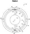
Figure 1 is a cross-sectional view of a rotating electrical machine according to an example of the invention, -
Figure 2 is a block diagram of a method according to an example of the invention for manufacturing a rotating electrical machine, and -
Figures 3 to 7 is a cross-sectional view of a rotating electrical machine during manufacturing. - Referring to
figure 1 , a rotatingelectrical machine 100 according to an example of the invention will now be described. - The
electrical machine 100 is for example asynchronous. Also for example, theelectrical machine 100 is designed to provide a high torque, for example included in the range 250 to 650 Nm. - The rotating
electrical machine 100 first comprises astator 102 for generating a stator magnetic field. - In the described example, the
stator 102 comprises acore 104 including acylindrical shell 106 and radial legs 108 (only two are shown) extending inwardly. Thestator 102 further comprises coils (not shown) wound around the legs. Thecore 104 comprises for example a lamination stack. - Preferably, the
stator 102 is provided withrecesses 110. In the described example, therecesses 110 comprises longitudinal grooves extending parallel to an rotation axis A on anouter surface 112 of thecore 104 of thestator 102, e.g. on an outer surface of thecylindrical shell 106. - The rotating
electrical machine 100 also comprises arotor 114 for generating a rotor magnetic field cooperating with the stator magnetic field to make therotor 114 rotate around the rotation axis A with respect to thestator 102. - The rotating
electrical machine 100 also comprises aninner housing 116 extending around thestator 102 and having anouter surface 118 and aninner surface 120 facing the outer surface of thestator 102. In the described example, theinner housing 116 is cylindrical. For example, theinner housing 116 is in aluminum. - The rotating
electrical machine 100 also comprises anouter housing 122 extending around theinner housing 116 and having aninner surface 124 facing theouter surface 118 of theinner housing 116. - The rotating
electrical machine 100 also comprisesconduits 126 in which a coolant is intended to flow to cool down the rotatingelectrical machine 100. - For example, each
conduit 126 may be formed by theinner housing 116 and theouter housing 122. More precisely, for example, theinner housing 116 may be provided with a groove forming a half conduit extending on itsouter surface 118 and theouter housing 122 may be provided with a complementary groove forming a complementary half conduit extending on itsinner surface 124. Alternatively, eachconduit 126 may be formed by a groove provided in theouter surface 118 of theinner housing 116 and covered by theouter housing 122. - Furthermore, the
conduits 126 may extend in the axial direction of the rotatingelectrical machine 100 or extend in any other direction. For instance, theconduits 126 may extend along a spiral around the axial direction of the rotatingelectrical machine 100. - Furthermore, the
inner housing 116 is provided with at least one deformation having the shape of a bump projecting inwardly. Twobumps 128 are shown onfigure 1 . Eachbump 128 is designed for cooperating with thestator 102 for preventing thestator 102 from rotating with respect to theinner housing 116, around the rotation axis A, during operation of the rotatingelectrical machine 100. - For example, the
bumps 128 may extend inrespective recesses 110 of thestator 102. - Also for example, a
blind hole 130 is provided on theouter surface 118 of theinner housing 116. In this manner, theblind hole 130 has an outward opening and abottom 132 deformed so as to form thebump 128. Thebump 128 can be sufficiently rigid to prevent alone any rotation between thestator 102 and thehousing 116. - However, the
bottom 132 may not be rigid enough to prevent a rotation of thestator 102 with respect to thehousing 116, for instance because there is not enough width between theouter surface 118 and theinner surface 120 of theinner housing 116. Then, arigid piece 134 may be located inside theblind hole 130 in order to rigidify thebump 128. Thisrigid piece 134 preferably presses against the bottom 132. Therigid piece 134 comprises for example a steel ball or a dowel pin. As it will be explained later with reference tofigures 2 to 7 , therigid piece 134 may also be used to deform the bottom 132 to create thebump 128. - Preferably,
walls 136 of theblind hole 130 are folded on therigid piece 134, opposite to the bottom 132, for maintaining therigid piece 134 inside theblind hole 130. In addition, glue may be added in theblind hole 130 to maintain therigid piece 134 inside theblind hole 130. Alternatively, only glue could be used for this purpose. - Referring to
figures 2 to 7 , amethod 200 according to the invention for manufacturing the rotatingelectrical machine 100 offigure 1 will now be described. - At a
step 202, thestator 102 is inserted into theinner housing 116. For example, theinner housing 116 is heated up to dilate. Thestator 102 is then inserted into the dilatedinner housing 116. Theinner housing 116 then cools down and presses against thestator 102. Alternatively, thestator 102 is inserted without heating theinner housing 116. The result is illustrated onfigure 3 . - Back to
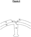
figure 2 , at astep 204, theblind hole 130 is made on theouter surface 118 of theinner housing 116, in particular inside one of the half conduits or outside the half conduits. Because thestator 102 was previously inserted into theinner housing 116 atstep 202, it is possible to make theblind hole 130 at a position radially aligned with one of therecesses 110 of thestator 102. The result is illustrated onfigure 4 . Alternatively, theblind hole 130 could be made before inserting thestator 102 into theinner housing 116. - Back to
figure 2 , at astep 206, therigid piece 134 is inserted into theblind hole 130 via the upward opening, against the bottom 132. The result is illustrated onfigure 5 . - Back to
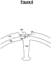
figure 2 , at astep 208, therigid piece 134 is pushed against the bottom 132 so as to deform the bottom 132 and create thebump 128. The result is illustrated onfigure 6 . - At a
step 210, thewalls 136 of theblind hole 130 are folded on therigid piece 134. The result is illustrated onfigure 7 . - At a
step 212, glue is inserted in theblind hole 130 to glue therigid piece 134 to theinner housing 116. Preferably, in order to avoid turbulences in the cooling fluid, theblind hole 130 is filled with the glue up until its upper edge. - In other embodiments, only one of
steps rigid piece 134 inside theblind hole 130. - It is clear that a rotating electrical machine such as the one described above allows the stator to be fixed to the housing.
- It will also be noted that the invention is not limited to the embodiments described above. It will indeed appear to those skilled in the art that various modifications can be made to the embodiments described above, in the light of the teaching which has just been disclosed.
- In the previous detailed description of the invention, the used terms should not be interpreted as limiting the invention to the embodiments presented in the present description, but should be interpreted to include all the equivalents within the reach of those skilled in the art by applying their general knowledge to the implementation of the teaching which has just been disclosed.
Claims (10)
- Rotating electrical machine (100) comprising:- a stator (102); and- an housing (116) extending around the stator (102);characterized in that the housing (116) is provided with a deformation having the shape of a bump (128) projecting inwardly for cooperating with the stator (102) for preventing the stator (102) from rotating with respect to the housing (116).
- Rotating electrical machine (100) according to claim 1, wherein the stator (102) has a recess (110) in which the bump (128) extends.
- Rotating electrical machine (100) according to claim 1 or 2, wherein the housing (116) is provided with a blind hole (130) with an outward opening and a bottom (132) comprising the bump (128), and comprising a rigid piece (134) located inside the blind hole (130), against the bottom (132).
- Rotating electrical machine (100) according to claim 3, wherein the blind hole (130) opens in a coolant flow conduit (126).
- Rotary electrical machine (100) according to claim 4, further comprising an outer housing (122) extending around said housing (116) provided with the bump (128), and wherein the two housings (116, 122) define together the coolant flow conduit (126).
- Rotating electrical machine (100) according to any of claims 3 to 5, wherein the rigid piece (134) is maintained inside the blind hole (130).
- Rotating electrical machine (100) according to claim 6, wherein the rigid piece (134) is maintained inside the blind hole (130) by walls (136) of the blind hole (130) folded on the rigid piece (134) opposite the bottom (132).
- Rotating electrical machine (100) according to claim 6 or 7, wherein the rigid piece (134) is maintained inside the blind hole (130) by glue provided in the blind hole (130).
- Method (200) for manufacturing a rotating electrical machine (100), comprising:- placing (202) a housing (116) around a stator (102);characterized by:- deforming (208) the housing (116) to create a bump (128) projecting inwardly for cooperating with the stator (102) so as to prevent the stator (102) from rotating with respect to the housing (116).
- Method (200) according to claim 9, comprising:- making (204) a blind hole (130) in the inner housing (116), with an outward opening and a bottom (132); and- inserting a rigid piece (134) inside the blind hole (130), against the bottom (132); andsaid step of deforming (208) the housing (116) to create the bump (128), including pushing the rigid piece (134) against the bottom (132) so as to deform the bottom (132) and create the bump (128).
Applications Claiming Priority (1)
| Application Number | Priority Date | Filing Date | Title |
|---|---|---|---|
| DE102020213532 | 2020-10-28 |
Publications (1)
| Publication Number | Publication Date |
|---|---|
| EP3993225A1 true EP3993225A1 (en) | 2022-05-04 |
Family
ID=78413766
Family Applications (1)
| Application Number | Title | Priority Date | Filing Date |
|---|---|---|---|
| EP21204935.7A Withdrawn EP3993225A1 (en) | 2020-10-28 | 2021-10-27 | Rotating electrical machine and method for manufacturing a rotating electrical machine |
Country Status (3)
| Country | Link |
|---|---|
| US (1) | US20220131437A1 (en) |
| EP (1) | EP3993225A1 (en) |
| CN (1) | CN114499007A (en) |
Citations (5)
| Publication number | Priority date | Publication date | Assignee | Title |
|---|---|---|---|---|
| JP2005278292A (en) * | 2004-03-24 | 2005-10-06 | Toyota Motor Corp | Stator core fixing structure |
| JP2009201235A (en) * | 2008-02-21 | 2009-09-03 | Jfe Steel Corp | Method for fixing stator of electric motor |
| KR20160040788A (en) * | 2014-10-06 | 2016-04-15 | 자화전자(주) | BLDC motor and fixing method of stator housing thereof |
| DE102018100165A1 (en) * | 2018-01-05 | 2019-07-11 | Webo Werkzeugbau Oberschwaben Gmbh | Fixed connection in a housing |
| DE102018110176A1 (en) * | 2018-04-27 | 2019-10-31 | Schaeffler Technologies AG & Co. KG | Electric motor and method for its production |
Family Cites Families (1)
| Publication number | Priority date | Publication date | Assignee | Title |
|---|---|---|---|---|
| DE102019215563A1 (en) * | 2019-10-10 | 2021-04-15 | Zf Friedrichshafen Ag | Stator of an electrical machine |
-
2021
- 2021-10-25 CN CN202111239346.3A patent/CN114499007A/en active Pending
- 2021-10-27 US US17/452,444 patent/US20220131437A1/en not_active Abandoned
- 2021-10-27 EP EP21204935.7A patent/EP3993225A1/en not_active Withdrawn
Patent Citations (5)
| Publication number | Priority date | Publication date | Assignee | Title |
|---|---|---|---|---|
| JP2005278292A (en) * | 2004-03-24 | 2005-10-06 | Toyota Motor Corp | Stator core fixing structure |
| JP2009201235A (en) * | 2008-02-21 | 2009-09-03 | Jfe Steel Corp | Method for fixing stator of electric motor |
| KR20160040788A (en) * | 2014-10-06 | 2016-04-15 | 자화전자(주) | BLDC motor and fixing method of stator housing thereof |
| DE102018100165A1 (en) * | 2018-01-05 | 2019-07-11 | Webo Werkzeugbau Oberschwaben Gmbh | Fixed connection in a housing |
| DE102018110176A1 (en) * | 2018-04-27 | 2019-10-31 | Schaeffler Technologies AG & Co. KG | Electric motor and method for its production |
Also Published As
| Publication number | Publication date |
|---|---|
| CN114499007A (en) | 2022-05-13 |
| US20220131437A1 (en) | 2022-04-28 |
Similar Documents
| Publication | Publication Date | Title |
|---|---|---|
| US9397541B2 (en) | Stator for electric rotating machine and method of manufacturing the same | |
| EP3058643B1 (en) | Electric motor | |
| US8074344B2 (en) | Method of manufacturing rotor holder | |
| US20090224628A1 (en) | Twin rotor type motor | |
| US20140097711A1 (en) | One piece rotor hub/shaft for an electric machine and method | |
| US12015331B2 (en) | Electric motor rotor with conformal heat pipes | |
| JPWO2020054233A1 (en) | Stator of rotary electric machine and rotary electric machine provided with the stator | |
| JP2017204984A (en) | Rotor of rotary electric machine, rotary electric machine, and method of manufacturing rotor of rotary electric machine | |
| EP2892128A2 (en) | Rotor and motor including the same | |
| CN115224879A (en) | Rotor cooling assembly and method for permanent magnet motor interior | |
| US20130193811A1 (en) | Induction rotor end ring support device | |
| CN107947397A (en) | Electric rotating motivation | |
| CN110556948B (en) | Rotor of rotating electrical machine and method of manufacturing the same, and rotating electrical machine | |
| US20220131437A1 (en) | Rotating electrical machine and method for manufacturing a rotating electrical machine | |
| CN111953095A (en) | Rotary motor | |
| JP4100170B2 (en) | Cooling structure of rotating electric machine | |
| CN101019294B (en) | Method for mounting magnet in motor rotor and motor rotor | |
| JP4855069B2 (en) | Manufacturing method of motor | |
| JP7404800B2 (en) | Rotor manufacturing method | |
| US10693356B2 (en) | Variable-field rotary electric machine and vehicle provided with same | |
| JP2020509731A (en) | Heat recovery stator assembly for electric machines | |
| CN110953250B (en) | Magnetic suspension bearing rotor structure, motor and air conditioner | |
| US12407229B2 (en) | Method for producing an intermediate product for an electrical machine, comprising a stator laminated core and a housing part, connected thereto, of the housing | |
| CN107257169A (en) | The processing method of teeth portion iron core blank, stator core and stator core | |
| CN109831062A (en) | The speed changer of integrated driving motor module and hybrid power assembly with it |
Legal Events
| Date | Code | Title | Description |
|---|---|---|---|
| PUAI | Public reference made under article 153(3) epc to a published international application that has entered the european phase |
Free format text: ORIGINAL CODE: 0009012 |
|
| STAA | Information on the status of an ep patent application or granted ep patent |
Free format text: STATUS: THE APPLICATION HAS BEEN PUBLISHED |
|
| AK | Designated contracting states |
Kind code of ref document: A1 Designated state(s): AL AT BE BG CH CY CZ DE DK EE ES FI FR GB GR HR HU IE IS IT LI LT LU LV MC MK MT NL NO PL PT RO RS SE SI SK SM TR |
|
| RAP3 | Party data changed (applicant data changed or rights of an application transferred) |
Owner name: VALEO EAUTOMOTIVE GERMANY GMBH |
|
| STAA | Information on the status of an ep patent application or granted ep patent |
Free format text: STATUS: REQUEST FOR EXAMINATION WAS MADE |
|
| 17P | Request for examination filed |
Effective date: 20221104 |
|
| RBV | Designated contracting states (corrected) |
Designated state(s): AL AT BE BG CH CY CZ DE DK EE ES FI FR GB GR HR HU IE IS IT LI LT LU LV MC MK MT NL NO PL PT RO RS SE SI SK SM TR |
|
| P01 | Opt-out of the competence of the unified patent court (upc) registered |
Effective date: 20230528 |
|
| STAA | Information on the status of an ep patent application or granted ep patent |
Free format text: STATUS: THE APPLICATION IS DEEMED TO BE WITHDRAWN |
|
| 18D | Application deemed to be withdrawn |
Effective date: 20250501 |