EP3993214A1 - Methods and systems for charging or discharging energy storage systems - Google Patents
Methods and systems for charging or discharging energy storage systems Download PDFInfo
- Publication number
- EP3993214A1 EP3993214A1 EP21200023.6A EP21200023A EP3993214A1 EP 3993214 A1 EP3993214 A1 EP 3993214A1 EP 21200023 A EP21200023 A EP 21200023A EP 3993214 A1 EP3993214 A1 EP 3993214A1
- Authority
- EP
- European Patent Office
- Prior art keywords
- discharge
- charge
- energy storage
- ess
- energy
- Prior art date
- Legal status (The legal status is an assumption and is not a legal conclusion. Google has not performed a legal analysis and makes no representation as to the accuracy of the status listed.)
- Pending
Links
Images


Classifications
-
- H—ELECTRICITY
- H02—GENERATION; CONVERSION OR DISTRIBUTION OF ELECTRIC POWER
- H02J—ELECTRIC POWER NETWORKS; CIRCUIT ARRANGEMENTS OR SYSTEMS FOR SUPPLYING OR DISTRIBUTING ELECTRIC POWER; SYSTEMS FOR STORING ELECTRIC ENERGY
- H02J3/00—Circuit arrangements for AC mains or AC distribution networks
- H02J3/38—Arrangements for feeding a single network from two or more generators or sources in parallel; Arrangements for feeding already energised networks from additional generators or sources in parallel
- H02J3/46—Controlling the sharing of generated power between the generators, sources or networks
- H02J3/48—Controlling the sharing of active power
-
- H—ELECTRICITY
- H02—GENERATION; CONVERSION OR DISTRIBUTION OF ELECTRIC POWER
- H02J—ELECTRIC POWER NETWORKS; CIRCUIT ARRANGEMENTS OR SYSTEMS FOR SUPPLYING OR DISTRIBUTING ELECTRIC POWER; SYSTEMS FOR STORING ELECTRIC ENERGY
- H02J7/00—Circuit arrangements for charging or discharging batteries or for supplying loads from batteries
- H02J7/50—Circuit arrangements for charging or discharging batteries or for supplying loads from batteries acting upon multiple batteries simultaneously or sequentially
-
- H—ELECTRICITY
- H01—ELECTRIC ELEMENTS
- H01M—PROCESSES OR MEANS, e.g. BATTERIES, FOR THE DIRECT CONVERSION OF CHEMICAL ENERGY INTO ELECTRICAL ENERGY
- H01M10/00—Secondary cells; Manufacture thereof
- H01M10/42—Methods or arrangements for servicing or maintenance of secondary cells or secondary half-cells
- H01M10/4207—Methods or arrangements for servicing or maintenance of secondary cells or secondary half-cells for several batteries or cells simultaneously or sequentially
-
- H—ELECTRICITY
- H02—GENERATION; CONVERSION OR DISTRIBUTION OF ELECTRIC POWER
- H02J—ELECTRIC POWER NETWORKS; CIRCUIT ARRANGEMENTS OR SYSTEMS FOR SUPPLYING OR DISTRIBUTING ELECTRIC POWER; SYSTEMS FOR STORING ELECTRIC ENERGY
- H02J3/00—Circuit arrangements for AC mains or AC distribution networks
- H02J3/04—Arrangements for connecting networks of the same frequency but supplied from different sources
- H02J3/06—Controlling the transfer of power between connected networks; Controlling load sharing between connected networks
-
- H—ELECTRICITY
- H02—GENERATION; CONVERSION OR DISTRIBUTION OF ELECTRIC POWER
- H02J—ELECTRIC POWER NETWORKS; CIRCUIT ARRANGEMENTS OR SYSTEMS FOR SUPPLYING OR DISTRIBUTING ELECTRIC POWER; SYSTEMS FOR STORING ELECTRIC ENERGY
- H02J3/00—Circuit arrangements for AC mains or AC distribution networks
- H02J3/28—Arrangements for balancing of the load in networks by storage of energy
-
- H—ELECTRICITY
- H02—GENERATION; CONVERSION OR DISTRIBUTION OF ELECTRIC POWER
- H02J—ELECTRIC POWER NETWORKS; CIRCUIT ARRANGEMENTS OR SYSTEMS FOR SUPPLYING OR DISTRIBUTING ELECTRIC POWER; SYSTEMS FOR STORING ELECTRIC ENERGY
- H02J3/00—Circuit arrangements for AC mains or AC distribution networks
- H02J3/28—Arrangements for balancing of the load in networks by storage of energy
- H02J3/32—Arrangements for balancing of the load in networks by storage of energy using batteries or super capacitors with converting means
-
- H—ELECTRICITY
- H01—ELECTRIC ELEMENTS
- H01M—PROCESSES OR MEANS, e.g. BATTERIES, FOR THE DIRECT CONVERSION OF CHEMICAL ENERGY INTO ELECTRICAL ENERGY
- H01M10/00—Secondary cells; Manufacture thereof
- H01M10/42—Methods or arrangements for servicing or maintenance of secondary cells or secondary half-cells
- H01M10/44—Methods for charging or discharging
- H01M10/441—Methods for charging or discharging for several batteries or cells simultaneously or sequentially
-
- H—ELECTRICITY
- H02—GENERATION; CONVERSION OR DISTRIBUTION OF ELECTRIC POWER
- H02J—ELECTRIC POWER NETWORKS; CIRCUIT ARRANGEMENTS OR SYSTEMS FOR SUPPLYING OR DISTRIBUTING ELECTRIC POWER; SYSTEMS FOR STORING ELECTRIC ENERGY
- H02J13/00—Circuit arrangements for providing remote monitoring or remote control of equipment in a power distribution network
- H02J13/14—Circuit arrangements for providing remote monitoring or remote control of equipment in a power distribution network the power network being locally controlled, e.g. home energy management systems [HEMS]
-
- H—ELECTRICITY
- H02—GENERATION; CONVERSION OR DISTRIBUTION OF ELECTRIC POWER
- H02J—ELECTRIC POWER NETWORKS; CIRCUIT ARRANGEMENTS OR SYSTEMS FOR SUPPLYING OR DISTRIBUTING ELECTRIC POWER; SYSTEMS FOR STORING ELECTRIC ENERGY
- H02J15/00—Systems for storing electric energy specially adapted for power networks
-
- H—ELECTRICITY
- H02—GENERATION; CONVERSION OR DISTRIBUTION OF ELECTRIC POWER
- H02J—ELECTRIC POWER NETWORKS; CIRCUIT ARRANGEMENTS OR SYSTEMS FOR SUPPLYING OR DISTRIBUTING ELECTRIC POWER; SYSTEMS FOR STORING ELECTRIC ENERGY
- H02J2105/00—Networks for supplying or distributing electric power characterised by their spatial reach or by the load
- H02J2105/10—Local stationary networks having a local or delimited stationary reach
-
- H—ELECTRICITY
- H02—GENERATION; CONVERSION OR DISTRIBUTION OF ELECTRIC POWER
- H02J—ELECTRIC POWER NETWORKS; CIRCUIT ARRANGEMENTS OR SYSTEMS FOR SUPPLYING OR DISTRIBUTING ELECTRIC POWER; SYSTEMS FOR STORING ELECTRIC ENERGY
- H02J2105/00—Networks for supplying or distributing electric power characterised by their spatial reach or by the load
- H02J2105/50—Networks for supplying or distributing electric power characterised by their spatial reach or by the load for selectively controlling the operation of the loads
- H02J2105/52—Networks for supplying or distributing electric power characterised by their spatial reach or by the load for selectively controlling the operation of the loads for limitation of the power consumption in the networks or in one section of the networks, e.g. load shedding or peak shaving
-
- H—ELECTRICITY
- H02—GENERATION; CONVERSION OR DISTRIBUTION OF ELECTRIC POWER
- H02J—ELECTRIC POWER NETWORKS; CIRCUIT ARRANGEMENTS OR SYSTEMS FOR SUPPLYING OR DISTRIBUTING ELECTRIC POWER; SYSTEMS FOR STORING ELECTRIC ENERGY
- H02J3/00—Circuit arrangements for AC mains or AC distribution networks
- H02J3/12—Arrangements for adjusting voltage in AC networks by changing a characteristic of the network load
- H02J3/14—Arrangements for adjusting voltage in AC networks by changing a characteristic of the network load by switching loads on to, or off from, the networks, e.g. progressively balanced loading
-
- H—ELECTRICITY
- H02—GENERATION; CONVERSION OR DISTRIBUTION OF ELECTRIC POWER
- H02J—ELECTRIC POWER NETWORKS; CIRCUIT ARRANGEMENTS OR SYSTEMS FOR SUPPLYING OR DISTRIBUTING ELECTRIC POWER; SYSTEMS FOR STORING ELECTRIC ENERGY
- H02J7/00—Circuit arrangements for charging or discharging batteries or for supplying loads from batteries
- H02J7/865—Battery or charger load switching, e.g. concurrent charging and load supply
-
- Y—GENERAL TAGGING OF NEW TECHNOLOGICAL DEVELOPMENTS; GENERAL TAGGING OF CROSS-SECTIONAL TECHNOLOGIES SPANNING OVER SEVERAL SECTIONS OF THE IPC; TECHNICAL SUBJECTS COVERED BY FORMER USPC CROSS-REFERENCE ART COLLECTIONS [XRACs] AND DIGESTS
- Y02—TECHNOLOGIES OR APPLICATIONS FOR MITIGATION OR ADAPTATION AGAINST CLIMATE CHANGE
- Y02B—CLIMATE CHANGE MITIGATION TECHNOLOGIES RELATED TO BUILDINGS, e.g. HOUSING, HOUSE APPLIANCES OR RELATED END-USER APPLICATIONS
- Y02B70/00—Technologies for an efficient end-user side electric power management and consumption
- Y02B70/30—Systems integrating technologies related to power network operation and communication or information technologies for improving the carbon footprint of the management of residential or tertiary loads, i.e. smart grids as climate change mitigation technology in the buildings sector, including also the last stages of power distribution and the control, monitoring or operating management systems at local level
- Y02B70/3225—Demand response systems, e.g. load shedding, peak shaving
-
- Y—GENERAL TAGGING OF NEW TECHNOLOGICAL DEVELOPMENTS; GENERAL TAGGING OF CROSS-SECTIONAL TECHNOLOGIES SPANNING OVER SEVERAL SECTIONS OF THE IPC; TECHNICAL SUBJECTS COVERED BY FORMER USPC CROSS-REFERENCE ART COLLECTIONS [XRACs] AND DIGESTS
- Y02—TECHNOLOGIES OR APPLICATIONS FOR MITIGATION OR ADAPTATION AGAINST CLIMATE CHANGE
- Y02P—CLIMATE CHANGE MITIGATION TECHNOLOGIES IN THE PRODUCTION OR PROCESSING OF GOODS
- Y02P80/00—Climate change mitigation technologies for sector-wide applications
- Y02P80/10—Efficient use of energy, e.g. using compressed air or pressurized fluid as energy carrier
- Y02P80/14—District level solutions, i.e. local energy networks
-
- Y—GENERAL TAGGING OF NEW TECHNOLOGICAL DEVELOPMENTS; GENERAL TAGGING OF CROSS-SECTIONAL TECHNOLOGIES SPANNING OVER SEVERAL SECTIONS OF THE IPC; TECHNICAL SUBJECTS COVERED BY FORMER USPC CROSS-REFERENCE ART COLLECTIONS [XRACs] AND DIGESTS
- Y04—INFORMATION OR COMMUNICATION TECHNOLOGIES HAVING AN IMPACT ON OTHER TECHNOLOGY AREAS
- Y04S—SYSTEMS INTEGRATING TECHNOLOGIES RELATED TO POWER NETWORK OPERATION, COMMUNICATION OR INFORMATION TECHNOLOGIES FOR IMPROVING THE ELECTRICAL POWER GENERATION, TRANSMISSION, DISTRIBUTION, MANAGEMENT OR USAGE, i.e. SMART GRIDS
- Y04S20/00—Management or operation of end-user stationary applications or the last stages of power distribution; Controlling, monitoring or operating thereof
- Y04S20/20—End-user application control systems
- Y04S20/222—Demand response systems, e.g. load shedding, peak shaving
Definitions
- the present disclosure relates generally to energy storage systems, and more particularly, to methods and systems for charging and/or discharging energy storage systems.
- Microgrids may include a plurality of different energy storage systems, such as different battery systems, fuel cells, etc.
- the different energy storage systems may have different power and energy capacities, and may be at different states of charge. With such varied characteristics between the energy storage systems, charging and discharging the systems in a balanced manner can be difficult. Unbalanced distribution of charge or discharge can affect the health or life of one or more of the energy storage systems, and thus negatively affect the microgrid.
- U.S. Patent No. 9,257,846 discloses a method for responding to a change in electric power demand. The method includes (1) charging an energy storage subsystem from an electric power grid, (2) discharging the energy storage subsystem into the electric power grid at a discharge rate that is less than a maximum rate of discharge of the energy storage subsystem, and (3) adjusting the discharge rate in response to a signal selected from the group consisting of a signal to provide a regulation up service and a signal to provide a regulation down service. While the system and methods of the '846 patent discuss adjusting a discharge rate, the patent relates to changes in demand and does not deal with a plurality of different energy storage systems.
- the present disclosure provides for a method of allocating power across a microgrid having a plurality of energy storage systems with different power and/or energy capacities, and different states of charge.
- the method includes allocating a total charge request and/or a total discharge request across the energy storage systems; and limiting the charge and/or discharge of one or more energy storage systems to a submaximal value.
- the present disclosure provides for a method of allocating power across a microgrid having a plurality of energy storage systems with different power and/or energy capacities, and different states of charge.
- the method includes allocating a total charge request and/or a total discharge request across the energy storage systems; and limiting the charge and/or discharge of each of the plurality of energy storage systems to a submaximal value for a limited window.
- the submaximal value is a function of the total desired charge or discharge request, and the limited window is the same for each of the plurality of the energy storage systems.
- the present disclosure provides for a microgrid system including a plurality of energy storage systems having different power and/or energy capacities, and different states of charge; and a microgrid controller communicatively coupled to each energy storage system for sending information to, and receiving information from, each energy storage system.
- the microgrid controller is configured to: allocate a total charge request and/or a total discharge request across the energy storage systems; and limit the charge and/or discharge of one or more energy storage systems to a submaximal value.
- FIG. 1 illustrates a microgrid 100 including a plurality of energy storage systems ("ESS") 110.
- ESS 110 may include a local controller 120, and each ESS 110 may be coupled to a power bus 130 for receiving and discharging charge.
- Microgrid 100 may also include a microgrid controller 140 communicatively coupled the local controller 120 of each ESS 110 across a communication bus 142.
- microgrid 100 may include a first energy storage system, ESS1 112, a second energy storage system, ESS2 114, a third energy storage system, ESS3 116, and an n-number energy storage system ESS(n) 118.
- Each ESS 110 may have a different configuration and be rated for a different power and energy capacity, as well as having a different state of charge ("SOC").
- ESSs 112, 114, 116, 118 may include one or more batteries, fuel cells, supercapacitors, and/or any other type of energy storage source.
- each ESS 110 may include any appropriate power electronics, such as switches, converters, and/or inverters to provide an appropriate interface between the ESS 110 and the power bus 130 and communication bus 142.
- the local controllers 120 may include controller1 122 associated with the ESS1 112, Controller2 124 associated with ESS2 114, Controller3 126 associated with ESS3 116, and Controller(n) 128 associated with ESS(n) 118.
- Each local controller 120 may include any appropriate hardware, software, firmware, etc. to sense and control ESS 110, and send information to, and receive information from, microgrid controller 140.
- local controller 120 may be configured to sense, determine, and/or store various characteristics of its respective energy storage system 110. Such characteristics of ESS 110 may include, among others, the current SOC, the current energy, the SOC minimum threshold, the SOC maximum threshold, and the discharge limit of ESS 110. These characteristics of ESS 110 may be sensed, determined, and/or stored in any conventional manner. While local controller 120 is described as a single controller, it is understood that controller 120 may include multiple controllers such that the functions associated with local controller 120 may be distributed among more than one controller.
- Microgrid controller 140 may include any appropriate hardware, software, firmware, etc. to sense, determine, and/or store various aspect of microgrid 100, and control various aspects of microgrid 100. Microgrid controller 140 may also send information to, and receive information from, each of the plurality of energy storage systems 112, 114, 116, 118 via respective ESS local controllers 122, 124, 126, 128. For example, microgrid controller 140 may receive or determine the need for charging or discharging of power from the microgrid 100, and may be configured to determine and send signals to allocate a total charge request and/or total discharge request across each of the plurality of energy storage systems 110.
- microgrid controller 140 may allocate a total charge request and/or a total discharge request across the energy storage systems as a function of a usable energy capacity of each energy storage system 110.
- the usable energy capacity corresponds to the capacity or amount of energy an energy storage system can receive in response to a total charging request (usable charge energy), or the capacity or amount of energy an energy storage system can discharge in response to a total discharge request (usable discharge energy).
- the usable charge energy is a function of a maximum state of charge, current state of charge, and current energy of the energy storage system
- the usable discharge energy is a function of a minimum state of charge, current state of charge, and current energy of the energy storage system.
- Microgrid controller 140 may determine a usable charge/discharge capacity of each ESS 110, a desired charge/discharge of each ESS 110, and a remainder power. While microgrid controller 140 is described as a single controller, it is understood microgrid controller 140 may include multiple controllers such that the functions discussed herein of microgrid controller 140 may be distributed among more than one controller.
- Microgrid controller 140 may send and receive information in any appropriate manner, using appropriate hardware, software, firmware, etc. and via wired and/or wireless systems. For example, as noted above, microgrid controller 140 may send and receive information to and from local controllers 120 of each ESS 110 via communication bus 142.
- FIG. 2 provides a method 200 for discharge power allocation across microgrid 100.
- method 200 may correspond to a supervisory or other request or instruction received at microgrid controller 140 to discharge a total desired discharge of power from the energy storage systems 110 of microgrid 100 to power bus 130.
- Method 200 may include: determining a useable discharge energy for each energy storage system 110 (step 202), determining a sum of useable discharge energy of microgrid 100 (step 204), determining a desired discharge from each energy storage system 110 (step 206), determining a remainder of desired discharge based on discharge limits (step 208), and allocating the remainder across unsaturated energy storage systems 110 until the total desired discharge is met (step 210).
- the discharge power allocation method of FIG. 2 may be performed within microgrid controller 140 such that microgrid controller sends a discharge request to each ESS 110, or one or more aspects of method 200 may be performed by other controllers or systems, such as local controllers 120.
- the determination of useable discharge energy for each energy storage system 110 may include reading the current energy from each ESS 110, determining the energy content of ESS 110 at an SOC minimum threshold, and determining a usable discharge energy of the ESS 110 as the difference between the current energy and energy at the minimum SOC threshold.
- the energy content of ESS 110 at SOC minimum threshold may be determined as an extrapolation from the current SOC of ESS 110 and the SOC minimum threshold.
- ESS(i) refers to ESS1 through ESS(n).
- Usable Discharge Energy of ESS i Current Energy of ESS i ⁇ Current Energy of ESS i * SOC min of ESS i / current SOC of ESS i
- Step 204 of method 200 the determined usable discharge energy of each ESS (112, 114, 116, 118) determined in accordance with Equation 1 is summed to provide a total usable energy of the microgrid 100.
- Usable Discharge Energy Total Sum Usable Discharge Energy of ESS i
- the microgrid controller 140 makes sure that the desired discharge of an ESS 110 does not exceed the discharge limit of the ESS 110. If the desired discharge for an ESS 110 would exceed the discharge limit for the ESS 110, microgrid controller establishes a remainder corresponding to the difference between the desired discharge and discharge limit for the ESS 110. See Equation 4 below. As provided in Equation 5 below, the remainders for each of the ESS 110 are then summed to find a reminder total.
- Step 210 of FIG. 2 includes the microgrid controller 140 distributing or allocating the total remainder to any ESS 110 that is not saturated - any ESS 110 that has not reached its discharge limit. The total remainder may then be allocated by determining a remaining desired discharge using a ratio of the remaining unsaturated ESS's 110 individual usable discharge energy to the usable discharged energy of all of the unsaturated ESSs. And this process is repeated until the remainder is zero.
- steps 206-210 determine the commands sent to each ESS 110 from the microgrid controller 140, and these commands are sent during these steps until the total desired discharge is met.
- the discharge request for each ESS includes the desired discharge plus any remaining desired discharge. This step 210 of method 200 may be further explained with the following equations.
- the discharge power allocation method 200 of FIG. 2 may be further explained with reference to the bar charts of FIGs. 3-5 .
- the charts of FIGs 3-5 seven energy storage systems 110 are used, with different discharge limits and usable discharge energy.
- FIG. 3 provides a chart where the bars represent the usable discharge energy for each ESS 110 in accordance with Equation 1 above. As shown in the chart, ESS 4 has the most usable discharge energy, and ESS2 and ESS5 have the least usable discharge energy.
- FIG. 3 shows usable discharge energy (e.g., kWh)
- FIG. 4 shows power allocation across each ESS 110 (e.g., kW).
- the power allocation is determined in accordance with Equations 3-7 above.
- each bar in FIG. 4 includes a first iteration desired discharge 410 corresponding to the desired discharge of the ESS in a first iteration of allocating the total desired discharge.
- the first iteration desired discharge 410 of ESS4 is larger than that of ESS2 and ESS5, indicating that ESS4 receives a greater power allocation in the first iteration than ESS2 and ESS5 because ESS 4 has a larger usable discharge energy.
- First iteration desired discharge 410 of ESS4, ESS6, and ESS7 extend the entire height of the bar, indicating that the desired discharge of the first iteration is greater than or equal to the discharge limit 412 of ESS4, ESS6, and ESS7 in accordance with Equation 4 above.
- these energy storage systems 110 may provide a remainder and the sum of these remainders corresponds to the total remainder of Equation 6 above.
- the first iteration desired discharge 410 of ESS1, ESS2, ESS3, and ESS5 is less than their respective discharge limits 412, and thus the total remainder may be allocated in accordance with Equation 6 to these energy storage systems 110.
- These energy storage systems will have second iteration remaining desired discharges 414, with those of ESS1 and ESS3 meeting or exceeding their respective discharge limits.
- ESS1 and ESS3 may thus provide another remainder to be allocated in accordance with Equation 6 to ESS2 and ESS5.
- These energy storage systems will have third iteration remaining desired discharges 416. Since these allocations do not meet the discharge limits for ESS2 or ESS5, then there is no remainder and the third iteration has allocated the total desired discharge.
- the discharge request sent from microgrid controller 140 to the local controllers 120 of each ESS 110 can be determined in accordance with Equation 7.
- the bar chart of FIG. 5 shows the total power accumulation across the three iterations. As shown, the first iteration provides for a desired discharge 510 and a total remainder 512, and the second iteration provides for a greater desired discharge 514 and smaller remainder 516. Iteration 3 includes a desired discharge 518 equal to the total desired discharge, and thus has no remainder.
- FIG. 6 provides a method 600 for charge power allocation across microgrid 100.
- Method 600 may correspond to a supervisory request received at microgrid controller 140 to charge a total desired charge of power to the energy storage systems 110 of microgrid 100 from power bus 130.
- Method 600 may include: determining a useable charge energy for each energy storage system 110 (step 602), determining a sum of useable charge energy of microgrid 100 (step 604), determining a desired charge to each energy storage system 110 (step 606), determining a remainder of desired charge based on charge limits (step 608), and allocating the remainder across unsaturated energy storage systems 110 until the total desired charge is met (step 610).
- the charge power allocation method of FIG. 6 may be performed within microgrid controller 140 such that microgrid controller sends a charge request to each ESS 110, or one or more aspects of method 600 may be performed by other controllers or systems, such as local controllers 120.
- the determination of useable charge energy for each energy storage system 110 (step 602) during charge power allocation may include reading the current energy from each ESS 110, determining the energy content of ESS 110 at an SOC maximum threshold, and determining a usable energy of the ESS 110 as the difference between the current energy and energy at the maximum threshold.
- the energy content of ESS 110 at SOC maximum threshold may be determined as an extrapolation from the current SOC of ESS 110 and the SOC maximum threshold.
- ESS(i) refers to ESS1 through ESS(n).
- Usable Charge Energy of ESS i Current Energy of ESS i ⁇ Current Energy of ESS i * SOC max of ESS i / SOC of ESS i
- Step 604 of method 600 the usable charge energy of each ESS 112, 114, 116, 118 is summed to provide a total usable charge energy of the microgrid 100.
- Usable Charge Energy Total Sum Usable Charge Energy of ESS i
- the microgrid controller 140 makes sure that the desired charge of an ESS 110 does not exceed the charge limit of the ESS 110. If the desired charge for an ESS 110 exceeds the charge limit for the ESS 110, microgrid controller establishes a remainder corresponding to the difference between the desired charge and charge limit for the ESS 110. The remainders for each of the ESS 110 are then summed to find a reminder total.
- Step 610 of FIG. 6 includes the microgrid controller 140 distributing or allocating the total remainder to any ESS 110 that is not saturated - any ESS 110 that has not reached its charge limit. The total remainder may then be allocated by determining a remaining desired charge using a ratio of the remaining unsaturated ESS's 110 individual usable charge energy to the usable charged energy of all of the unsaturated ESSs 110. And this process is repeated until the remainder is zero. Thus, steps 606-610 determine the commands sent to each ESS 110 from the microgrid controller 140, and these commands are sent during these steps until the total desired charge is met. The charge request for each ESS includes the desired charge plus any remaining desired charge.
- the method of discharge or charge allocation 200, 600 may include the same steps 702, 704, 706, 708, 710 as method 200 (and 600 in a charging process), and may include the additional step 712 of limiting the maximum discharge limits (or charge limits) for one or more energy storage systems 110 to a submaximal value for a limiting window, after which the discharge limit will increase linearly to their respective maximum value to meet the desired total discharge/charge request.
- This method step 712 of FIG. 7 can be further explained with reference to FIG. 8 and an exemplary microgrid 100 having four online energy storage systems 110, e.g., batteries 1-4.
- a total desired discharge (2500 Kw) is received by, or determined in, microgrid controller 140 as discussed above.
- Each ESS of FIG. 8 has a different discharge limit, as shown by the horizontal lines 812 identified for each ESS 110, and these discharge limits 812 sum to the total desired discharge (2500 Kw).
- the discharge 820 of each of the ESSs 110 may be limited to a submaximal discharge limit in accordance with Equation 15 below.
- the submaximal discharge limit values are identified with horizontal lines 822 for each ESS 110 in FIG. 8 , with the submaximal value being the discharge limit of an ESS 110 multiplied by a convergence factor.
- Submaximal Discharge Limit i Discharge Limit i * Convergence Factor
- the convergence factor may be a constant value, such as (0.7 or 70%), and may be stored or otherwise determined and applied by microgrid controller 140.
- each ESS is discharged to its respective submaximal value until all of the ESSs 110 reach their submaximal discharge limits.
- Battery 2 reaches its submaximal discharge limit 822 first, at approximately 30% of the total desired discharge.
- Battery 1 then meets its submaximal discharge limit 822 (at approximately 45% of the total desired discharge), followed by Battery 4 at approximately 60% of the total desired discharge, and finally Battery 3 reaches its submaximal discharge limit 822 at approximately 70% of the total desired discharge.
- the microgrid 100 may avoid maximum discharging (or charging) of each energy storage system 110 for the limiting window.
- using the submaximal discharge limit 822 may allow one ESS to use more of its discharge limit (812), while allowing other energy storage systems having a lower discharge limit 812 to back off of their discharge limits 812, with none of the ESSs 110 reaching max discharge limit (or charge limit) during the limiting window.
- max discharge limit or charge limit
- the disclosed methods and systems for charging and/or discharging energy storage systems may be used in any microgrid-type system that sends and receives power.
- the methods and systems disclosed herein may provide a balancing of state of charge (SOC) and power distribution across energy storage systems 110 of a microgrid 100 when the energy storage systems 110 of the microgrid 100 have different power and/or energy capacities and different states of charge.
- SOC state of charge
- the method and systems allow for microgrid controller 140 to provide asymmetric charge or discharge requests as a function of usable capacity of each energy storage system 110.
- the systems and methods disclosed herein may allow the SOC of each energy storage system 110 to eventually converge when the rated capacities of energy storage systems are different. Providing such a balancing of the SOC of the energy storage systems 110 may extend the health and life of the systems, and thus may extend the health and life of the microgrid 100.
- performing the step 712 of the method of FIG. 7 may limit the amount of time an ESS 110 is running at maximum discharge / charge. Limiting the running of the energy storage systems 110 at maximum power may extend the health and life of the systems, and may provide for a more stable microgrid 100.
Landscapes
- Engineering & Computer Science (AREA)
- Power Engineering (AREA)
- Manufacturing & Machinery (AREA)
- Chemical & Material Sciences (AREA)
- Chemical Kinetics & Catalysis (AREA)
- Electrochemistry (AREA)
- General Chemical & Material Sciences (AREA)
- Supply And Distribution Of Alternating Current (AREA)
- Charge And Discharge Circuits For Batteries Or The Like (AREA)
Abstract
Description
- The present disclosure relates generally to energy storage systems, and more particularly, to methods and systems for charging and/or discharging energy storage systems.
- The present disclosure relates to the control of microgrids that send and receive power. Microgrids may include a plurality of different energy storage systems, such as different battery systems, fuel cells, etc. The different energy storage systems may have different power and energy capacities, and may be at different states of charge. With such varied characteristics between the energy storage systems, charging and discharging the systems in a balanced manner can be difficult. Unbalanced distribution of charge or discharge can affect the health or life of one or more of the energy storage systems, and thus negatively affect the microgrid.
-
U.S. Patent No. 9,257,846 - The systems and method of the present disclosure may solve one or more of the problems set forth above and/or other problems in the art. The scope of the current disclosure, however, is defined by the attached claims, and not by the ability to solve any specific problem.
- The present disclosure provides for a method of allocating power across a microgrid having a plurality of energy storage systems with different power and/or energy capacities, and different states of charge. The method includes allocating a total charge request and/or a total discharge request across the energy storage systems; and limiting the charge and/or discharge of one or more energy storage systems to a submaximal value.
- In another aspect, the present disclosure provides for a method of allocating power across a microgrid having a plurality of energy storage systems with different power and/or energy capacities, and different states of charge. The method includes allocating a total charge request and/or a total discharge request across the energy storage systems; and limiting the charge and/or discharge of each of the plurality of energy storage systems to a submaximal value for a limited window. The submaximal value is a function of the total desired charge or discharge request, and the limited window is the same for each of the plurality of the energy storage systems.
- In yet another aspect, the present disclosure provides for a microgrid system including a plurality of energy storage systems having different power and/or energy capacities, and different states of charge; and a microgrid controller communicatively coupled to each energy storage system for sending information to, and receiving information from, each energy storage system. The microgrid controller is configured to: allocate a total charge request and/or a total discharge request across the energy storage systems; and limit the charge and/or discharge of one or more energy storage systems to a submaximal value.
-
-
FIG. 1 illustrates an exemplary microgrid according to the present disclosure; -
FIG. 2 provides a method for discharge power allocation across the microgrid ofFIG. 1 ; -
FIG. 3 illustrates an exemplary bar chart of usable discharge energy of energy storage systems of the microgrid ofFIG. 1 ; -
FIG. 4 illustrates an exemplary bar chart of iterative power increase per energy storage system of the microgrid ofFIG. 1 ; -
FIG. 5 illustrates an exemplary bar chart of total power accumulation through iterations for the microgrid ofFIG. 1 ; -
FIG. 6 provides a method for charge power allocation across the microgrid ofFIG. 1 ; -
FIG. 7 provides a method for discharge power allocation across the microgrid ofFIG. 1 with submaximal discharge; and -
FIG. 8 provides charts of the discharge of four energy storage systems, in accordance with the method ofFIG. 7 - Both the foregoing general description and the following detailed description are exemplary and explanatory only and are not restrictive of the features, as claimed. The same reference numbers in different alternatives are used to describe the same components or functions. As used herein, the terms "comprises," "comprising," "having," "including," or other variations thereof, are intended to cover a non-exclusive inclusion such that a process, method, article, or apparatus that comprises a list of elements does not include only those elements, but may include other elements not expressly listed or inherent to such a process, method, article, or apparatus. In this disclosure, relative terms, such as, for example, "about," "substantially," "generally," and "approximately" are used to indicate a possible variation of ±10% in a stated value or characteristic.
-
FIG. 1 illustrates amicrogrid 100 including a plurality of energy storage systems ("ESS") 110. Each ESS 110 may include alocal controller 120, and each ESS 110 may be coupled to apower bus 130 for receiving and discharging charge. Microgrid 100 may also include amicrogrid controller 140 communicatively coupled thelocal controller 120 of each ESS 110 across acommunication bus 142. - Any number of
energy storage systems 110 could be included inmicrogrid 100. For example, as shown inFIG. 1 ,microgrid 100 may include a first energy storage system, ESS1 112, a second energy storage system,ESS2 114, a third energy storage system,ESS3 116, and an n-number energy storage system ESS(n) 118. Each ESS 110 may have a different configuration and be rated for a different power and energy capacity, as well as having a different state of charge ("SOC").ESSs local controller 120, each ESS 110 may include any appropriate power electronics, such as switches, converters, and/or inverters to provide an appropriate interface between the ESS 110 and thepower bus 130 andcommunication bus 142. - Referring still to
FIG. 1 , thelocal controllers 120 may includecontroller1 122 associated with theESS1 112,Controller2 124 associated withESS2 114,Controller3 126 associated withESS3 116, and Controller(n) 128 associated with ESS(n) 118. Eachlocal controller 120 may include any appropriate hardware, software, firmware, etc. to sense and controlESS 110, and send information to, and receive information from,microgrid controller 140. For example,local controller 120 may be configured to sense, determine, and/or store various characteristics of its respectiveenergy storage system 110. Such characteristics ofESS 110 may include, among others, the current SOC, the current energy, the SOC minimum threshold, the SOC maximum threshold, and the discharge limit ofESS 110. These characteristics of ESS 110 may be sensed, determined, and/or stored in any conventional manner. Whilelocal controller 120 is described as a single controller, it is understood thatcontroller 120 may include multiple controllers such that the functions associated withlocal controller 120 may be distributed among more than one controller. -
Microgrid controller 140 may include any appropriate hardware, software, firmware, etc. to sense, determine, and/or store various aspect ofmicrogrid 100, and control various aspects ofmicrogrid 100.Microgrid controller 140 may also send information to, and receive information from, each of the plurality ofenergy storage systems local controllers microgrid controller 140 may receive or determine the need for charging or discharging of power from themicrogrid 100, and may be configured to determine and send signals to allocate a total charge request and/or total discharge request across each of the plurality ofenergy storage systems 110. - As will be discussed in more detail below, when performing the power allocation functions,
microgrid controller 140 may allocate a total charge request and/or a total discharge request across the energy storage systems as a function of a usable energy capacity of eachenergy storage system 110. The usable energy capacity corresponds to the capacity or amount of energy an energy storage system can receive in response to a total charging request (usable charge energy), or the capacity or amount of energy an energy storage system can discharge in response to a total discharge request (usable discharge energy). The usable charge energy is a function of a maximum state of charge, current state of charge, and current energy of the energy storage system, and the usable discharge energy is a function of a minimum state of charge, current state of charge, and current energy of the energy storage system.Microgrid controller 140 may determine a usable charge/discharge capacity of eachESS 110, a desired charge/discharge of eachESS 110, and a remainder power. Whilemicrogrid controller 140 is described as a single controller, it is understoodmicrogrid controller 140 may include multiple controllers such that the functions discussed herein ofmicrogrid controller 140 may be distributed among more than one controller. - Microgrid
controller 140 may send and receive information in any appropriate manner, using appropriate hardware, software, firmware, etc. and via wired and/or wireless systems. For example, as noted above,microgrid controller 140 may send and receive information to and fromlocal controllers 120 of each ESS 110 viacommunication bus 142. -
FIG. 2 provides amethod 200 for discharge power allocation acrossmicrogrid 100. Thus,method 200 may correspond to a supervisory or other request or instruction received atmicrogrid controller 140 to discharge a total desired discharge of power from theenergy storage systems 110 ofmicrogrid 100 topower bus 130.Method 200 may include: determining a useable discharge energy for each energy storage system 110 (step 202), determining a sum of useable discharge energy of microgrid 100 (step 204), determining a desired discharge from each energy storage system 110 (step 206), determining a remainder of desired discharge based on discharge limits (step 208), and allocating the remainder across unsaturatedenergy storage systems 110 until the total desired discharge is met (step 210). The discharge power allocation method ofFIG. 2 may be performed withinmicrogrid controller 140 such that microgrid controller sends a discharge request to eachESS 110, or one or more aspects ofmethod 200 may be performed by other controllers or systems, such aslocal controllers 120. - The determination of useable discharge energy for each energy storage system 110 (step 202) may include reading the current energy from each
ESS 110, determining the energy content ofESS 110 at an SOC minimum threshold, and determining a usable discharge energy of theESS 110 as the difference between the current energy and energy at the minimum SOC threshold. As provided in theEquation 1 below, the energy content ofESS 110 at SOC minimum threshold may be determined as an extrapolation from the current SOC ofESS 110 and the SOC minimum threshold. In this equation, and the equations that follow, ESS(i) refers to ESS1 through ESS(n).
- In
Step 204 ofmethod 200, the determined usable discharge energy of each ESS (112, 114, 116, 118) determined in accordance withEquation 1 is summed to provide a total usable energy of themicrogrid 100.
- In Step 206 a desired discharge is determined for each
energy storage system 110. This can be determined by multiplying the total desired discharge of themicrogrid 100 by the ratio of the Usable Discharge Energy (Equation 1) of an individualenergy storage system 110 to the Usable Discharge Energy Total (Equation 2).
- When the
method 200 moves to step 208 - determining a remainder of desired discharge based on discharge limits - themicrogrid controller 140 makes sure that the desired discharge of anESS 110 does not exceed the discharge limit of theESS 110. If the desired discharge for anESS 110 would exceed the discharge limit for theESS 110, microgrid controller establishes a remainder corresponding to the difference between the desired discharge and discharge limit for theESS 110. SeeEquation 4 below. As provided inEquation 5 below, the remainders for each of theESS 110 are then summed to find a reminder total.

- Step 210 of
FIG. 2 includes themicrogrid controller 140 distributing or allocating the total remainder to anyESS 110 that is not saturated - anyESS 110 that has not reached its discharge limit. The total remainder may then be allocated by determining a remaining desired discharge using a ratio of the remaining unsaturated ESS's 110 individual usable discharge energy to the usable discharged energy of all of the unsaturated ESSs. And this process is repeated until the remainder is zero. Thus, steps 206-210 determine the commands sent to eachESS 110 from themicrogrid controller 140, and these commands are sent during these steps until the total desired discharge is met. The discharge request for each ESS includes the desired discharge plus any remaining desired discharge. Thisstep 210 ofmethod 200 may be further explained with the following equations.

- The discharge
power allocation method 200 ofFIG. 2 may be further explained with reference to the bar charts ofFIGs. 3-5 . In the charts ofFIGs 3-5 , sevenenergy storage systems 110 are used, with different discharge limits and usable discharge energy.FIG. 3 provides a chart where the bars represent the usable discharge energy for eachESS 110 in accordance withEquation 1 above. As shown in the chart,ESS 4 has the most usable discharge energy, and ESS2 and ESS5 have the least usable discharge energy. - While
FIG. 3 shows usable discharge energy (e.g., kWh),FIG. 4 shows power allocation across each ESS 110 (e.g., kW). The power allocation is determined in accordance with Equations 3-7 above. In particular, each bar inFIG. 4 includes a first iteration desireddischarge 410 corresponding to the desired discharge of the ESS in a first iteration of allocating the total desired discharge. As provided byEquation 3 above, the first iteration desireddischarge 410 of ESS4 is larger than that of ESS2 and ESS5, indicating that ESS4 receives a greater power allocation in the first iteration than ESS2 and ESS5 becauseESS 4 has a larger usable discharge energy. - First iteration desired
discharge 410 of ESS4, ESS6, and ESS7 extend the entire height of the bar, indicating that the desired discharge of the first iteration is greater than or equal to thedischarge limit 412 of ESS4, ESS6, and ESS7 in accordance withEquation 4 above. Thus, theseenergy storage systems 110 may provide a remainder and the sum of these remainders corresponds to the total remainder ofEquation 6 above. The first iteration desireddischarge 410 of ESS1, ESS2, ESS3, and ESS5 is less than their respective discharge limits 412, and thus the total remainder may be allocated in accordance withEquation 6 to theseenergy storage systems 110. These energy storage systems will have second iteration remaining desireddischarges 414, with those of ESS1 and ESS3 meeting or exceeding their respective discharge limits. ESS1 and ESS3 may thus provide another remainder to be allocated in accordance withEquation 6 to ESS2 and ESS5. These energy storage systems will have third iteration remaining desired discharges 416. Since these allocations do not meet the discharge limits for ESS2 or ESS5, then there is no remainder and the third iteration has allocated the total desired discharge. At this point, the discharge request sent frommicrogrid controller 140 to thelocal controllers 120 of eachESS 110 can be determined in accordance withEquation 7. - The bar chart of
FIG. 5 shows the total power accumulation across the three iterations. As shown, the first iteration provides for a desireddischarge 510 and atotal remainder 512, and the second iteration provides for a greater desired discharge 514 andsmaller remainder 516.Iteration 3 includes a desireddischarge 518 equal to the total desired discharge, and thus has no remainder. - The previous discussion of
FIGS. 2-5 addressed discharge power allocation. When microgridcontroller 140 receives a total charge request, the request may be allocated to eachESS 110 in a manner similar to that described above for discharge power allocation.FIG. 6 provides amethod 600 for charge power allocation acrossmicrogrid 100.Method 600 may correspond to a supervisory request received atmicrogrid controller 140 to charge a total desired charge of power to theenergy storage systems 110 ofmicrogrid 100 frompower bus 130.Method 600 may include: determining a useable charge energy for each energy storage system 110 (step 602), determining a sum of useable charge energy of microgrid 100 (step 604), determining a desired charge to each energy storage system 110 (step 606), determining a remainder of desired charge based on charge limits (step 608), and allocating the remainder across unsaturatedenergy storage systems 110 until the total desired charge is met (step 610). The charge power allocation method ofFIG. 6 may be performed withinmicrogrid controller 140 such that microgrid controller sends a charge request to eachESS 110, or one or more aspects ofmethod 600 may be performed by other controllers or systems, such aslocal controllers 120. - The determination of useable charge energy for each energy storage system 110 (step 602) during charge power allocation may include reading the current energy from each
ESS 110, determining the energy content ofESS 110 at an SOC maximum threshold, and determining a usable energy of theESS 110 as the difference between the current energy and energy at the maximum threshold. As provide in the equation below, the energy content ofESS 110 at SOC maximum threshold may be determined as an extrapolation from the current SOC ofESS 110 and the SOC maximum threshold. In this equation, and the equations that follow, ESS(i) refers to ESS1 through ESS(n).
- In
Step 604 ofmethod 600, the usable charge energy of eachESS microgrid 100.
- In Step 606 a desired charge is determined for each
energy storage system 110. This can include multiplying the total desired charge of themicrogrid 100 by the ratio of the usable charge of an individualenergy storage system 110 to the total usable charge energy.
- When the
method 600 moves to step 608 - determining a remainder of desired charge based on charge limits - themicrogrid controller 140 makes sure that the desired charge of anESS 110 does not exceed the charge limit of theESS 110. If the desired charge for anESS 110 exceeds the charge limit for theESS 110, microgrid controller establishes a remainder corresponding to the difference between the desired charge and charge limit for theESS 110. The remainders for each of theESS 110 are then summed to find a reminder total.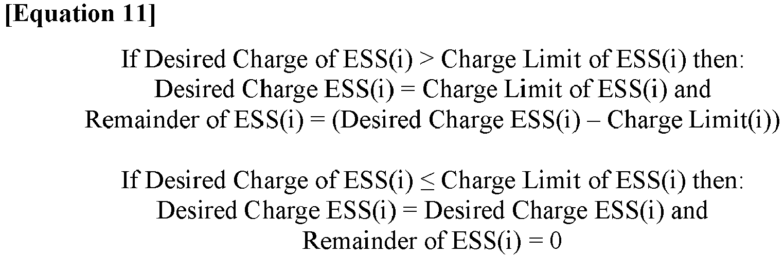

- Step 610 of
FIG. 6 includes themicrogrid controller 140 distributing or allocating the total remainder to anyESS 110 that is not saturated - anyESS 110 that has not reached its charge limit. The total remainder may then be allocated by determining a remaining desired charge using a ratio of the remaining unsaturated ESS's 110 individual usable charge energy to the usable charged energy of all of theunsaturated ESSs 110. And this process is repeated until the remainder is zero. Thus, steps 606-610 determine the commands sent to eachESS 110 from themicrogrid controller 140, and these commands are sent during these steps until the total desired charge is met. The charge request for each ESS includes the desired charge plus any remaining desired charge. Thisstep 210 ofmethod 200 may be further explained with the following equations.

- In another aspect of the present disclosure shown in
FIG. 7 , the method of discharge orcharge allocation 200, 600 (FIG. 2 ,FIG. 6 ) may include thesame steps additional step 712 of limiting the maximum discharge limits (or charge limits) for one or moreenergy storage systems 110 to a submaximal value for a limiting window, after which the discharge limit will increase linearly to their respective maximum value to meet the desired total discharge/charge request. - This
method step 712 ofFIG. 7 can be further explained with reference toFIG. 8 and anexemplary microgrid 100 having four onlineenergy storage systems 110, e.g., batteries 1-4. In this example, a total desired discharge (2500 Kw) is received by, or determined in,microgrid controller 140 as discussed above. Each ESS ofFIG. 8 has a different discharge limit, as shown by thehorizontal lines 812 identified for eachESS 110, and thesedischarge limits 812 sum to the total desired discharge (2500 Kw). Thedischarge 820 of each of theESSs 110 may be limited to a submaximal discharge limit in accordance with Equation 15 below. The submaximal discharge limit values are identified withhorizontal lines 822 for eachESS 110 inFIG. 8 , with the submaximal value being the discharge limit of anESS 110 multiplied by a convergence factor.
- The convergence factor may be a constant value, such as (0.7 or 70%), and may be stored or otherwise determined and applied by
microgrid controller 140. As shown inFIG. 8 , each ESS is discharged to its respective submaximal value until all of theESSs 110 reach their submaximal discharge limits. As shown inFIG. 8 ,Battery 2 reaches itssubmaximal discharge limit 822 first, at approximately 30% of the total desired discharge.Battery 1 then meets its submaximal discharge limit 822 (at approximately 45% of the total desired discharge), followed byBattery 4 at approximately 60% of the total desired discharge, and finallyBattery 3 reaches itssubmaximal discharge limit 822 at approximately 70% of the total desired discharge. As shown by the horizontal portion ofdischarge 820 for eachESS 110,Batteries Battery 3 to reach itssubmaximal discharge limit 822. This period where all of theESSs 110 are being discharged to their submaximal discharge limit 822 (and waiting for the last of the ESSs to reach its submaximal discharge limit 822) corresponds to the limiting window of theESSs 110 in accordance withstep 712 ofFIG. 7 . After this limiting window, all of the ESSs are discharged linearly to theirdischarge limit 812 to meet the total desired discharge (2500 Kw). This is shown by the linear increase of eachdischarge 820 from approximately 70% of the total desired discharge to the total desired discharge (100%). - By using the submaximal discharge limit (step 712), the
microgrid 100 may avoid maximum discharging (or charging) of eachenergy storage system 110 for the limiting window. For example, using thesubmaximal discharge limit 822 may allow one ESS to use more of its discharge limit (812), while allowing other energy storage systems having alower discharge limit 812 to back off of theirdischarge limits 812, with none of theESSs 110 reaching max discharge limit (or charge limit) during the limiting window. Thus, such a system may help thoseenergy storage systems 110 having a lower discharge limit from running at maximum discharge / charge during the entire discharge / charge process. - The disclosed methods and systems for charging and/or discharging energy storage systems may be used in any microgrid-type system that sends and receives power.
- The methods and systems disclosed herein may provide a balancing of state of charge (SOC) and power distribution across
energy storage systems 110 of amicrogrid 100 when theenergy storage systems 110 of themicrogrid 100 have different power and/or energy capacities and different states of charge. The method and systems allow formicrogrid controller 140 to provide asymmetric charge or discharge requests as a function of usable capacity of eachenergy storage system 110. With this, the systems and methods disclosed herein may allow the SOC of eachenergy storage system 110 to eventually converge when the rated capacities of energy storage systems are different. Providing such a balancing of the SOC of theenergy storage systems 110 may extend the health and life of the systems, and thus may extend the health and life of themicrogrid 100. - Further, as noted above, performing the
step 712 of the method ofFIG. 7 may limit the amount of time anESS 110 is running at maximum discharge / charge. Limiting the running of theenergy storage systems 110 at maximum power may extend the health and life of the systems, and may provide for a morestable microgrid 100. - It will be apparent to those skilled in the art that various modifications and variations can be made to the disclosed machine without departing from the scope of the disclosure. Other embodiments of the machine will be apparent to those skilled in the art from consideration of the specification and practice of the system and methods described herein. For example, the above described process steps need not be performed in the order described, but rather certain steps can be performed in a different order and/or can be performed simultaneously with other steps. Further, it is understood that one or more of the
energy storage systems 110 ofmicrogrid 100 may be excluded or offline from the charge or discharge allocations provided above. It is intended that the specification and examples be considered as exemplary only, with a true scope of the disclosure being indicated by the following claims and their equivalents.
Claims (10)
- A method (200) of allocating power across a microgrid (100) having a plurality of energy storage systems (110) with different power and/or energy capacities, and different states of charge; the method (200) comprising:allocating a total charge request and/or a total discharge request across the energy storage systems (110); andlimiting the charge and/or discharge of one or more energy storage systems (110) to a submaximal value.
- The method (200) of allocating power according to claim 1, wherein the limiting to the submaximal value occurs for a limited window.
- The method (200) of allocating power according to claim 2, wherein, after the limiting window, the charge and/or discharge is increased linearly to a charge limit and/or discharge limit (412).
- The method (200) of allocating power according to claim 2, where the limited window corresponds to a convergence value applied to each energy storage system.
- The method (200) of allocating power according to claim 4, wherein the convergence value is a stored value in a controller of the microgrid (100), and is the same for each energy storage system.
- The method (200) of allocating power according to claim 1, wherein the submaximal value is a function of the charge or discharge limits (412) of the plurality of the energy storage systems (110).
- The method (200) of allocating power according to claim 1, wherein the submaximal value corresponds to a charge limit or discharge limit (412) of an energy storage system multiplied by a percentage value of the total desired charge or discharge request.
- The method (200) of allocating power according to claim 1, wherein the limiting of the charge or discharge is applied to each of the plurality of energy storage systems (110).
- The method (200) of allocating power according to claim 1, wherein the energy storage systems (110) include at least one of a battery system or a fuel cell system.
- The method (200) of allocating power according to claim 1, wherein the microgrid (100) allocates both the total charge request and the total discharge request.
Applications Claiming Priority (1)
| Application Number | Priority Date | Filing Date | Title |
|---|---|---|---|
| US17/081,077 US11888334B2 (en) | 2020-10-27 | 2020-10-27 | Methods and systems for charging or discharging energy storage systems |
Publications (1)
| Publication Number | Publication Date |
|---|---|
| EP3993214A1 true EP3993214A1 (en) | 2022-05-04 |
Family
ID=78179212
Family Applications (1)
| Application Number | Title | Priority Date | Filing Date |
|---|---|---|---|
| EP21200023.6A Pending EP3993214A1 (en) | 2020-10-27 | 2021-09-29 | Methods and systems for charging or discharging energy storage systems |
Country Status (3)
| Country | Link |
|---|---|
| US (1) | US11888334B2 (en) |
| EP (1) | EP3993214A1 (en) |
| CN (1) | CN114498943A (en) |
Families Citing this family (11)
| Publication number | Priority date | Publication date | Assignee | Title |
|---|---|---|---|---|
| DE102019208042A1 (en) * | 2019-06-03 | 2020-12-03 | Robert Bosch Gmbh | Method for operating an electrical energy store, electrical energy store and device |
| JP2021191095A (en) * | 2020-05-29 | 2021-12-13 | 株式会社日立製作所 | Power storage system control device, power storage system, and program |
| EP4176505A1 (en) * | 2020-07-01 | 2023-05-10 | Vestas Wind Systems A/S | Battery testing in operation |
| US12500423B2 (en) | 2020-07-24 | 2025-12-16 | Voltagrid Llc | Mobile hybrid microgrid |
| WO2022020805A1 (en) | 2020-07-24 | 2022-01-27 | Voltagrid Llc | Common bus switchgear for mobile hybrid micro-grids |
| US20230261466A1 (en) * | 2022-02-16 | 2023-08-17 | Toyota Motor North America, Inc. | Management of power storage in anticipation of peak usage time |
| US12418179B2 (en) * | 2022-06-02 | 2025-09-16 | Honeywell International Inc. | System and apparatus for the control of battery energy storage systems |
| US12463428B2 (en) | 2023-10-04 | 2025-11-04 | Caterpillar Inc. | Systems and methods for multiple energy storage system dispatch |
| US20250379450A1 (en) * | 2024-06-06 | 2025-12-11 | Caterpillar Inc. | Optimized control method for power distribution scheduling in a microgrid controller |
| US12531422B2 (en) | 2024-06-06 | 2026-01-20 | Caterpillar Inc. | Flexible load stabilization modes for a power distribution system |
| US12489296B1 (en) | 2024-08-12 | 2025-12-02 | Caterpillar Inc. | Energy storage system dispatch strategy for multiple non-energy-storage systems with charge restrictions |
Citations (3)
| Publication number | Priority date | Publication date | Assignee | Title |
|---|---|---|---|---|
| EP2463981A1 (en) * | 2009-08-04 | 2012-06-13 | Nec Corporation | Energy system |
| US9257846B2 (en) | 2009-08-17 | 2016-02-09 | Vionx Energy Corporation | Energy storage systems and associated methods |
| US20200301383A1 (en) * | 2019-03-18 | 2020-09-24 | Caterpillar Inc. | Energy management system with gensets and energy storage |
Family Cites Families (61)
| Publication number | Priority date | Publication date | Assignee | Title |
|---|---|---|---|---|
| US5600226A (en) * | 1993-10-13 | 1997-02-04 | Galaxy Power, Inc. A Pennsylvania Corporation | Methods of controlling the application and termination of charge to a rechargeable battery |
| US6094051A (en) * | 1998-09-15 | 2000-07-25 | Alliedsignal Inc. | Apparatus and method for detecting memory effect in nickel cadmium batteries |
| US5926008A (en) * | 1998-09-15 | 1999-07-20 | Alliedsignal Inc. | Apparatus and method for determining the capacity of a nickel-cadmium battery |
| US7256516B2 (en) * | 2000-06-14 | 2007-08-14 | Aerovironment Inc. | Battery charging system and method |
| US7348760B2 (en) * | 2000-09-21 | 2008-03-25 | O2Micro International Limited | Power management topologies |
| US6757590B2 (en) * | 2001-03-15 | 2004-06-29 | Utc Fuel Cells, Llc | Control of multiple fuel cell power plants at a site to provide a distributed resource in a utility grid |
| US7353083B2 (en) * | 2004-01-15 | 2008-04-01 | Vrb Power Systems Inc. | Vanadium redox battery energy storage and power generation system incorporating and optimizing diesel engine generators |
| US7554292B2 (en) * | 2006-06-21 | 2009-06-30 | Research In Motion Limited | Battery charger for simultaneously charging a plurality of batteries |
| US8987939B2 (en) * | 2007-11-30 | 2015-03-24 | Caterpillar Inc. | Hybrid power system with variable speed genset |
| US9002761B2 (en) * | 2008-10-08 | 2015-04-07 | Rey Montalvo | Method and system for automatically adapting end user power usage |
| CN102209655B (en) * | 2008-11-10 | 2015-05-06 | 住友重机械工业株式会社 | Hybrid construction machine |
| JP5331493B2 (en) * | 2009-01-13 | 2013-10-30 | 日立ビークルエナジー株式会社 | Battery control device |
| WO2010083334A1 (en) * | 2009-01-14 | 2010-07-22 | Integral Analytics, Inc. | Optimization of microgrid energy use and distribution |
| US8315745B2 (en) * | 2009-04-24 | 2012-11-20 | Hunter Defense Technologies, Inc. | Mobile micro-grid power system controller and method |
| US8640629B2 (en) * | 2009-05-01 | 2014-02-04 | Norfolk Southern Corporation | Battery-powered all-electric and/or hybrid locomotive and related locomotive and train configurations |
| US8136454B2 (en) * | 2009-05-01 | 2012-03-20 | Norfolk Southern Corporation | Battery-powered all-electric locomotive and related locomotive and train configurations |
| JP5628820B2 (en) * | 2009-10-05 | 2014-11-19 | 日本碍子株式会社 | Control device, control device network, and control method |
| CN102511118B (en) * | 2009-10-05 | 2014-08-06 | 日本碍子株式会社 | Control device, control device network, and control method |
| US8401709B2 (en) * | 2009-11-03 | 2013-03-19 | Spirae, Inc. | Dynamic distributed power grid control system |
| AU2011272799B2 (en) * | 2010-06-30 | 2014-10-30 | Ergotron, Inc. | Electrical load management system and method |
| US8626348B2 (en) * | 2010-11-18 | 2014-01-07 | Sears Brands, L.L.C. | Methods and systems for community energy management |
| US9203263B2 (en) * | 2011-01-18 | 2015-12-01 | Sears Brands, L.L.C. | Methods and systems for providing an appliance hybrid mode |
| US8957634B2 (en) * | 2011-03-15 | 2015-02-17 | Siemens Aktiengesellschaft | Network as automation platform for collaborative E-car charging at the residential premises |
| TWI424656B (en) * | 2011-04-01 | 2014-01-21 | 立錡科技股份有限公司 | Charging current control method |
| US20130002027A1 (en) * | 2011-06-30 | 2013-01-03 | Caterpillar Inc. | Uninterruptible power supply |
| US8810198B2 (en) * | 2011-09-02 | 2014-08-19 | Tesla Motors, Inc. | Multiport vehicle DC charging system with variable power distribution according to power distribution rules |
| US9077198B2 (en) * | 2011-12-30 | 2015-07-07 | Thomas Szepesi | Battery charging method and circuit |
| US9018898B2 (en) * | 2012-02-10 | 2015-04-28 | Sandisk Technologies Inc. | Regulation of wirelessly charging multiple devices from the same source |
| US9367108B2 (en) * | 2012-06-28 | 2016-06-14 | Nec Corporation | Reduction of operational cost using energy storage management and demand response |
| US20140350743A1 (en) * | 2012-08-27 | 2014-11-27 | Nec Laboratories America, Inc. | Tiered power management system for microgrids |
| US10439429B2 (en) * | 2012-11-02 | 2019-10-08 | Lex Products, Llc | Modular microgrid unit and method of use |
| US9042141B2 (en) * | 2013-02-07 | 2015-05-26 | Caterpillar Inc. | Control of energy storage system inverter system in a microgrid application |
| JP6371845B2 (en) * | 2013-07-23 | 2018-08-08 | コーニンクレッカ フィリップス エヌ ヴェKoninklijke Philips N.V. | Photovoltaic and battery operating system and method for controlling the same |
| US9660455B2 (en) * | 2013-10-03 | 2017-05-23 | Caterpillar Inc. | System and method for increasing efficiency of gensets in micro-grid systems |
| JP6552796B2 (en) * | 2014-09-03 | 2019-07-31 | 株式会社東芝 | Power storage control device |
| US10139846B2 (en) * | 2014-11-16 | 2018-11-27 | Marvin Motsenbocker | DC power grid and equipment |
| US20160190822A1 (en) * | 2014-12-30 | 2016-06-30 | Lg Cns Co., Ltd. | Microgrid energy management system and power storage method for energy storage system |
| US10297877B2 (en) * | 2015-03-16 | 2019-05-21 | Kabushiki Kaisha Toshiba | Storage battery control device and storage battery control method |
| US9722445B2 (en) * | 2015-08-31 | 2017-08-01 | Caterpillar Inc. | Control of hybrid energy storage system for high pulse load |
| US10186889B2 (en) * | 2015-10-08 | 2019-01-22 | Taurus Des, Llc | Electrical energy storage system with variable state-of-charge frequency response optimization |
| US10592833B2 (en) * | 2016-04-01 | 2020-03-17 | Enel X North America, Inc. | Extended control in control systems and methods for economical optimization of an electrical system |
| US10571947B2 (en) * | 2016-05-13 | 2020-02-25 | Stem, Inc. | Increasing the demand reduction effectiveness of an energy storage system |
| US9871396B2 (en) * | 2016-06-21 | 2018-01-16 | General Electric Company | System and method for controlling charge of an energy storage device from a renewable energy source |
| US9889915B2 (en) * | 2016-06-30 | 2018-02-13 | Caterpillar Inc. | Systems, apparatuses, and methods to control output power of groups of engines |
| US10146242B2 (en) * | 2016-08-25 | 2018-12-04 | Caterpillar Inc. | Micro grid power system |
| US10848098B2 (en) * | 2016-12-11 | 2020-11-24 | Sandeep Agarwal | Smart energy storage system |
| CN106786958B (en) * | 2017-01-13 | 2019-06-14 | Oppo广东移动通信有限公司 | Charging method, device and terminal |
| US10345888B2 (en) * | 2017-03-15 | 2019-07-09 | International Business Machines Corporation | Power capping for power consumption devices with multiple power supplies |
| US10590860B2 (en) * | 2017-04-14 | 2020-03-17 | Solar Turbines Incorporated | Engine load estimation strategy in gas turbine engine system |
| US10700521B2 (en) * | 2017-04-28 | 2020-06-30 | Lsis Co., Ltd. | Hierarchical type power control system |
| CN107370171B (en) | 2017-07-13 | 2021-07-06 | 北京索英电气技术有限公司 | A method for optimal configuration and coordinated control of large-scale energy storage in an independent microgrid |
| US10554046B2 (en) * | 2017-12-18 | 2020-02-04 | International Business Machines Corporation | Virtualization of large-scale energy storage |
| JP2019118170A (en) * | 2017-12-26 | 2019-07-18 | パナソニックIpマネジメント株式会社 | Power control device, power control method, and program |
| US11336111B2 (en) * | 2018-06-08 | 2022-05-17 | Powin, Llc | Microgrid power system |
| DE102018129429A1 (en) * | 2018-11-22 | 2020-05-28 | Wobben Properties Gmbh | Feed-in process for a wind energy system and wind energy system |
| US10998732B2 (en) * | 2019-03-20 | 2021-05-04 | Caterpillar Inc. | System and method for diverse multi-source energy management |
| CN110336268A (en) | 2019-05-07 | 2019-10-15 | 国网湖南省电力有限公司 | Charge/discharge control method for energy storage reversible transducer |
| US11177664B2 (en) * | 2019-11-01 | 2021-11-16 | Caterpillar Inc. | System and method for dynamic voltage regulation of an engine on a variable frequency bus |
| US11894682B2 (en) * | 2020-05-15 | 2024-02-06 | Caterpillar Inc. | Methods and systems for off-grid load stabilization of energy distribution systems |
| US11742664B2 (en) * | 2020-10-27 | 2023-08-29 | Caterpillar Inc. | Methods and systems for charging or discharging energy storage systems |
| FR3116162A1 (en) * | 2020-11-06 | 2022-05-13 | Schneider Electric Industries Sas | Methods and systems for automatically configuring an electrical microgrid |
-
2020
- 2020-10-27 US US17/081,077 patent/US11888334B2/en active Active
-
2021
- 2021-09-29 EP EP21200023.6A patent/EP3993214A1/en active Pending
- 2021-10-27 CN CN202111253577.XA patent/CN114498943A/en active Pending
Patent Citations (3)
| Publication number | Priority date | Publication date | Assignee | Title |
|---|---|---|---|---|
| EP2463981A1 (en) * | 2009-08-04 | 2012-06-13 | Nec Corporation | Energy system |
| US9257846B2 (en) | 2009-08-17 | 2016-02-09 | Vionx Energy Corporation | Energy storage systems and associated methods |
| US20200301383A1 (en) * | 2019-03-18 | 2020-09-24 | Caterpillar Inc. | Energy management system with gensets and energy storage |
Also Published As
| Publication number | Publication date |
|---|---|
| US20220131388A1 (en) | 2022-04-28 |
| CN114498943A (en) | 2022-05-13 |
| US11888334B2 (en) | 2024-01-30 |
Similar Documents
| Publication | Publication Date | Title |
|---|---|---|
| EP3993214A1 (en) | Methods and systems for charging or discharging energy storage systems | |
| EP3993213A1 (en) | Methods and systems for charging or discharging energy storage systems | |
| KR101725701B1 (en) | Secondary cell system having plurality of cells, and method for distributing charge/discharge electric power or current | |
| EP4303601B1 (en) | Energy storage system control method and energy storage system | |
| US20160352111A1 (en) | Control system for electric storage system | |
| US11509153B2 (en) | Charge/discharge control method for storage system and charge/discharge control device | |
| CN113602131B (en) | Ordered charging and discharging method for electric automobile based on optimizing power quality of distribution transformer area | |
| EP2738912A1 (en) | Battery system | |
| CN110120680B (en) | Power distribution method and device of energy storage system | |
| JPWO2016158551A1 (en) | Distributed power storage system, power control method, and program | |
| CN115986883B (en) | Energy storage system and control method thereof | |
| JP7399695B2 (en) | Charge/discharge control method for power storage system and charge/discharge control device | |
| CN118232447A (en) | Battery control method, device, computer equipment and medium | |
| JP2016163400A (en) | Controller, control method, and program | |
| CN118232456A (en) | Power distribution method, electronic device and storage medium | |
| EP4729345A1 (en) | Power adjustment method and system based on charging piles, and electronic device and storage medium | |
| US20190148780A1 (en) | Charge and discharge control apparatus and method for an energy storage that provides multiple services | |
| CN117239799A (en) | Energy storage power station power distribution method, device, equipment and storage medium | |
| US20160280091A1 (en) | Managing the exchange of electrical power with rechargeable vehicle batteries in v2x systems | |
| EP4510421A1 (en) | Charge/discharge control device, charge/discharge control method, and program | |
| EP4293856B1 (en) | Charge/discharge control method for charging/discharging element and charge/discharge control device for charging/discharging element | |
| US9669720B2 (en) | Managing the exchange of electrical power with rechargeable vehicle batteries in V2X systems | |
| JP7599561B2 (en) | Storage battery system and method for controlling charging and discharging of storage battery system | |
| CN117220272A (en) | Method, system, equipment and storage medium for distributing power of battery energy storage power station | |
| JP7771687B2 (en) | Battery System |
Legal Events
| Date | Code | Title | Description |
|---|---|---|---|
| PUAI | Public reference made under article 153(3) epc to a published international application that has entered the european phase |
Free format text: ORIGINAL CODE: 0009012 |
|
| STAA | Information on the status of an ep patent application or granted ep patent |
Free format text: STATUS: THE APPLICATION HAS BEEN PUBLISHED |
|
| AK | Designated contracting states |
Kind code of ref document: A1 Designated state(s): AL AT BE BG CH CY CZ DE DK EE ES FI FR GB GR HR HU IE IS IT LI LT LU LV MC MK MT NL NO PL PT RO RS SE SI SK SM TR |
|
| STAA | Information on the status of an ep patent application or granted ep patent |
Free format text: STATUS: REQUEST FOR EXAMINATION WAS MADE |
|
| 17P | Request for examination filed |
Effective date: 20221104 |
|
| RBV | Designated contracting states (corrected) |
Designated state(s): AL AT BE BG CH CY CZ DE DK EE ES FI FR GB GR HR HU IE IS IT LI LT LU LV MC MK MT NL NO PL PT RO RS SE SI SK SM TR |