EP3993201A1 - Cable clamp and cable clamping assembly and cable clamping method thereof - Google Patents
Cable clamp and cable clamping assembly and cable clamping method thereof Download PDFInfo
- Publication number
- EP3993201A1 EP3993201A1 EP21181761.4A EP21181761A EP3993201A1 EP 3993201 A1 EP3993201 A1 EP 3993201A1 EP 21181761 A EP21181761 A EP 21181761A EP 3993201 A1 EP3993201 A1 EP 3993201A1
- Authority
- EP
- European Patent Office
- Prior art keywords
- cable
- latching components
- bendable arms
- concave portion
- clamp
- Prior art date
- Legal status (The legal status is an assumption and is not a legal conclusion. Google has not performed a legal analysis and makes no representation as to the accuracy of the status listed.)
- Pending
Links
- 238000000034 method Methods 0.000 title claims description 27
- 238000003825 pressing Methods 0.000 claims abstract description 20
- 230000004044 response Effects 0.000 claims abstract description 12
- 230000009975 flexible effect Effects 0.000 claims description 6
- 238000005452 bending Methods 0.000 claims description 4
- 239000000463 material Substances 0.000 claims description 4
- 230000008569 process Effects 0.000 description 15
- 239000002184 metal Substances 0.000 description 7
- 230000002708 enhancing effect Effects 0.000 description 2
- 238000004519 manufacturing process Methods 0.000 description 2
- 230000008901 benefit Effects 0.000 description 1
- 230000008878 coupling Effects 0.000 description 1
- 238000010168 coupling process Methods 0.000 description 1
- 238000005859 coupling reaction Methods 0.000 description 1
- 238000005516 engineering process Methods 0.000 description 1
- 238000009434 installation Methods 0.000 description 1
- 230000007246 mechanism Effects 0.000 description 1
Images




Classifications
-
- H—ELECTRICITY
- H02—GENERATION; CONVERSION OR DISTRIBUTION OF ELECTRIC POWER
- H02G—INSTALLATION OF ELECTRIC CABLES OR LINES, OR OF COMBINED OPTICAL AND ELECTRIC CABLES OR LINES
- H02G3/00—Installations of electric cables or lines or protective tubing therefor in or on buildings, equivalent structures or vehicles
- H02G3/30—Installations of cables or lines on walls, floors or ceilings
- H02G3/32—Installations of cables or lines on walls, floors or ceilings using mounting clamps
-
- H—ELECTRICITY
- H02—GENERATION; CONVERSION OR DISTRIBUTION OF ELECTRIC POWER
- H02G—INSTALLATION OF ELECTRIC CABLES OR LINES, OR OF COMBINED OPTICAL AND ELECTRIC CABLES OR LINES
- H02G3/00—Installations of electric cables or lines or protective tubing therefor in or on buildings, equivalent structures or vehicles
- H02G3/02—Details
- H02G3/04—Protective tubing or conduits, e.g. cable ladders or cable troughs
-
- H—ELECTRICITY
- H02—GENERATION; CONVERSION OR DISTRIBUTION OF ELECTRIC POWER
- H02G—INSTALLATION OF ELECTRIC CABLES OR LINES, OR OF COMBINED OPTICAL AND ELECTRIC CABLES OR LINES
- H02G3/00—Installations of electric cables or lines or protective tubing therefor in or on buildings, equivalent structures or vehicles
- H02G3/02—Details
-
- F—MECHANICAL ENGINEERING; LIGHTING; HEATING; WEAPONS; BLASTING
- F16—ENGINEERING ELEMENTS AND UNITS; GENERAL MEASURES FOR PRODUCING AND MAINTAINING EFFECTIVE FUNCTIONING OF MACHINES OR INSTALLATIONS; THERMAL INSULATION IN GENERAL
- F16B—DEVICES FOR FASTENING OR SECURING CONSTRUCTIONAL ELEMENTS OR MACHINE PARTS TOGETHER, e.g. NAILS, BOLTS, CIRCLIPS, CLAMPS, CLIPS OR WEDGES; JOINTS OR JOINTING
- F16B9/00—Connections of rods or tubular parts to flat surfaces at an angle
- F16B9/02—Detachable connections
-
- H—ELECTRICITY
- H02—GENERATION; CONVERSION OR DISTRIBUTION OF ELECTRIC POWER
- H02G—INSTALLATION OF ELECTRIC CABLES OR LINES, OR OF COMBINED OPTICAL AND ELECTRIC CABLES OR LINES
- H02G1/00—Methods or apparatus specially adapted for installing, maintaining, repairing or dismantling electric cables or lines
- H02G1/06—Methods or apparatus specially adapted for installing, maintaining, repairing or dismantling electric cables or lines for laying cables, e.g. laying apparatus on vehicle
-
- H—ELECTRICITY
- H02—GENERATION; CONVERSION OR DISTRIBUTION OF ELECTRIC POWER
- H02G—INSTALLATION OF ELECTRIC CABLES OR LINES, OR OF COMBINED OPTICAL AND ELECTRIC CABLES OR LINES
- H02G3/00—Installations of electric cables or lines or protective tubing therefor in or on buildings, equivalent structures or vehicles
- H02G3/02—Details
- H02G3/06—Joints for connecting lengths of protective tubing or channels, to each other or to casings, e.g. to distribution boxes; Ensuring electrical continuity in the joint
- H02G3/0616—Joints for connecting tubing to casing
- H02G3/0625—Joints for connecting tubing to casing with means for preventing disengagement of conductors
- H02G3/0666—Joints for connecting tubing to casing with means for preventing disengagement of conductors with means clamping the armour of the conductor
Definitions
- the present disclosure relates to a cable clamping assembly, and more particularly to a cable clamping assembly having an open cable clamp to clamp cables fast and convenient.
- clips are usually used to manage the internal cables.
- a closed metal collar is usually used as the clips to manage cable.
- the cable managing process is first to sleeve the metal collar on the cables to be managed, and then the ends of the cables are coupled or welded to the corresponding electronic component. While, the assembly process needs to sleeve the metal collar on the cables by manual assembly.
- the cable clamp includes a protruding base and two bendable arms.
- the two bendable arms surround a cable.
- the protruding base is deformed in response to a pressing force. Consequently, the cable is tied by the bendable arms firmly, and the plurality of first latching components lock with the plurality of second latching components. Consequently, the tightness of clamping cable by cable clamp the can be adjustable, and the assembling process is more precisely and reliable.
- the cable clamping assembly includes a cable clamp and a supporting base.
- a cable is disposed in a concave portion of the supporting base.
- the two bendable arms respectively slide downwardly along two ends of a guiding slope of the concave portion to surround the cable, until one of the two bendable arms is stopped by the positioning portion.
- the protruding base is deformed in response to a pressing force, so that the bendable arms tie the cable closely, and the plurality of first latching components lock with the plurality of second latching components. Consequently, the disadvantages of time-consuming, inconvenient assembly, low producing efficiency and lacking applicable of the prior art can be avoided.
- cable clamp including a protruding base and two bendable arms.
- the protruding base has a top surface, wherein an opening is disposed on the center of the top surface, so as to enhance the structure strength.
- the two bendable arms respectively include a plurality of first latching components and a plurality of second latching components.
- the two bendable arms surround a cable.
- the protruding base is deformed in response to a pressing force, so that the bendable arms tie the cable closely, and the plurality of first latching components lock with the plurality of second latching components.
- the cable clamp is made of a flexible material.
- the two bendable arms are respectively connected to the two corresponding side of the protruding base.
- the plurality of first latching components are a plurality of protruding portions
- the plurality of second latching components are a plurality of holes, when the plurality of first latching components are latched to the plurality of second latching components, at least one of the plurality of protruding portions are respectively locked in at least one of the plurality of holes.
- a cable clamping assembly comprising a cable clamp and a supporting base.
- the cable clamp includes a protruding base and two bendable arms.
- the two bendable arms respectively include a plurality of first latching components and a plurality of second latching components.
- the supporting base includes a concave portion. A guiding slope and a positioning portion are disposed within the concave portion.
- the concave portion of the supporting base is a semicircular concave portion.
- the concave portion includes a first surface, a second surface and a third surface, the third surface connects with the first surface and the second surface, and there is a height difference between the first surface and the second surface.
- the guiding slope of the concave portion is defined by the second surface and the third surface.
- a cable clamping method First, a cable clamp and a supporting base are provided.
- the cable clamp includes a protruding base and two bendable arms.
- the two bendable arms respectively include a plurality of first latching components and a plurality of second latching components.
- the supporting base including a concave portion.
- a cable is provided, and the cable is disposed in the concave portion of the supporting base.
- the two bendable arms respectively slide downwardly along two ends of a guiding slope of the concave portion to surround the cable, until one of the two bendable arms being stopped by the positioning portion.
- the protruding base is deformed in response to a pressing force, so that the bendable arms tie the cable firmly, and the plurality of first latching components lock with the plurality of second latching components.
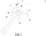
- FIG. 1 is a schematic perspective view illustrating a cable clamping assembly clamping a cable according to an embodiment of the present disclosure.
- the cable clamping assembly 1 includes a cable clamp 2 and a supporting base 3.
- the cable clamp 2 includes a protruding base 20 and two bendable arms 21 and 22.
- the two bendable arms 21 and 22 respectively include a plurality of first latching components 21a and a plurality of second latching components 22a (as shown in FIG. 3 ), but not limited thereto.
- the supporting base 3 includes a concave portion 31.
- a guiding slope 32 and a positioning portion 33 are disposed within the concave portion 31.
- At least a cable 4 is placed in the concave portion 31 of the supporting base 3.
- the cable clamp 2 is downward disposed and in correspondence to the concave portion 31 of the supporting base 3.
- the two bendable arms 21 and 22 respectively slide downwardly along two ends 32a and 32b of the guiding slope 32 to surround the cable 4, until one of the two bendable arms 21 and 22 is stopped by the positioning portion 33.
- the protruding base 20 is deformed in response to a pressing force, so that the two bendable arms 21 and 22 are near to each other, and the plurality of first latching components 21a lock with the plurality of second latching components 22a. Consequently, the cable 4 is clamped and firmly fixed by the cable clamp 2.
- FIG. 2 is a schematic perspective view illustrating the cable clamping assembly according to the embodiment of the present disclosure.
- FIG. 3 is a schematic perspective view illustrating the open state of a cable clamp of the cable clamping assembly according to the embodiment of the present disclosure.
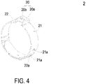
- FIG. 4 is a schematic perspective view illustrating the cable clamp according to the embodiment of the present disclosure.
- the cable clamp 2 is an open cable clamp, which means the two bendable arms 21 and 22 are not touched with each other at the initial state.
- the cable clamp 2 is made of a flexible material, but not limited thereto.
- the flexible material may be metal or flexible rubber, etc. Due to the flexible property, the two arms 21 and 22 are bendable, so that they can be latched with each other. Please refer to FIG.3 , for easily to see the structure of the cable clamp 2, the two arms 21 and 22 are illustrated as an opened flat state, while they are bended during the utilized state. Please refer to FIGS. 1 to 4 .
- the two arms 21 and 22 of the cable clamp 2 is a first arm 21 and a second arm 22, wherein the first arm 21 and the second arm 22 are respectively connected to the two corresponding side of the protruding base 20.
- the protruding base 20, the first arm 21 and the second arm 22 are an integrated structure, but not limited thereto.
- the protruding base 20 is a protruding stage structure and includes a top surface 20a.
- the top surface 20a has a height difference to the first arm 21 and the second arm 22.
- the first arm 21 and the second arm 22 of the cable clamp 2 respectively include a plurality of first latching components 21a and a plurality of second latching components 22a.
- the plurality of first latching components 21a can be but not limited to be a plurality of protruding portions.
- the plurality of second latching components 22a can be but not limited to be a plurality of holes. When the plurality of first latching components 21a are latched to the plurality of second latching components 22a, at least one of the plurality of protruding portions are respectively locked in at least one of the plurality of holes. While, in some embodiments, the types of the first latching components 21a and the second latching components 22a may be varied.
- first latching components 21a and the second latching components 22a may be hooking structures, magnetic structures or other tight fitting manners corresponding with each other, but not limited thereto.
- the purpose of the first latching components 21a and the second latching components 22a are coupling and fixing with each other, and the types of which may be varied according to the practical requirements.
- the plurality of protruding portions of the first latching components 21a are respectively locked in the plurality of holes of the second latching components 22a, so that the first arm 21 and the second arm 22 of the cable clamp 2 are firmly fixed with each other. Consequently, the cable 4 is tightly fixed by the cable clamp 2 as shown in FIG. 1 .
- FIG. 5 is a schematic perspective view illustrating a supporting base of the cable clamping assembly according to the embodiment of the present disclosure.
- the supporting base 3 can be but not limited to be a cube structure and includes an upper surface 30.
- the concave portion 31 is formed by a portion of the upper surface 30 recessed inwardly.
- the concave portion 31 of the supporting base 3 is a semicircular concave portion, but not limited thereto.
- the types of the concave portion 31 and the supporting base 3 are not limited to the above embodiments, and can be adjustable according the practical requirement.
- the concave portion 31 includes a first surface 34, a second surface 35 and a third surface 36.
- the third surface 36 connects with the first surface 34 and the second surface 35, and there is a height difference between the first surface 34 and the second surface 35.
- the concave portion 31 is a semicircular concave portion, and the inner surface of the concave portion 31 are composed of the first surface 34 and the second surface 35, and the third surface 36 vertically connects between the first surface 34 and the second surface 35, so as to form the height difference between the first surface 34 and the second surface 35.
- the first surface 34 and the second surface 35 are not coplanar, and the height difference between the first surface 34 and the second surface 35 is defined by the third surface 36.
- the guiding slope 32 of the concave portion 31 is defined by the second surface 35 and the third surface 36.
- the guiding slope 32 has two ends, which are the first end 32a and the second end 32b.
- the positioning portion 33 is formed on the second surface 35, and is formed by bending the second surface 35.
- the positioning portion 33 is a step structure formed by bending the second surface 35, but not limited thereto. Please refer to FIG. 2 again, the first arm 21 and the second arm 22 slide downwardly from the first end 32a and the second end 32b, and then slide downwardly along the guiding slope 32, until one of the first arm 21 and the second arm 22 is stopped by the positioning portion 33.
- the second arm 22 is stopped by the positioning portion 33, so as to limit the movement of the second arm 22. Since the second arm 22 is stopped by the positioning portion 33, when the pressing force keeps on delivered to the first arm 21, the first arm 21 can be pressed closely, so as to adjust the latching positions of the corresponding first latching components 21a and the second latching components 21a. Consequently, the tightness of the cable clamp 2 clamping the cable 4 can be adjustable.
- the positioning portion 33 can be but not limited to be a protruding rib or other stopped structure, which is not limited to the above embodiments, and can be adjustable according the practical requirement.
- FIG. 6 is a flowchart illustrating a cable clamping method according to an embodiment of the present disclosure.
- the cable clamp 2 is for holding and fixing the cable 4.
- the cable 4 may be but not limited to be a cable bundle composed of a plurality of cables 40.
- the cable 4 may be a single cable 4, the number of the cable 4 may be changed according to the practical requirements.
- FIG. 6 which is the cable clamping method for the cable clamp 2 clamping the cable 4. First, in a step S50, a cable clamp 2 and a supporting base 3 as shown in FIGS.
- the cable clamp 2 includes a protruding base 20 and two bendable arms 21 and 22.
- the two bendable arms 21 and 22 respectively include a plurality of first latching components 21a and a plurality of second latching components 22a.
- the supporting base 3 included a concave portion 31. Then, in a step S51, a cable 4 is provided, and the cable 4 is corresponding disposed in the concave portion 31 of the supporting base 3.
- the cable clamp 2 is disposed downwardly in correspondence to the concave portion 31 of the supporting base 3, so that the first arm 21 and the second arm 22 of the cable clamp 2 respectively slide downwardly along the first end 32a and the second end 32b of the guiding slope 32 of the concave portion 31, and the first arm 21 and the second arm 22 are near and covered with each other. Consequently, the cable 4 disposed in the concave portion 31 is surrounded by the first arm 21 and the second arm 22.
- the first arm 21 and the second arm 22 keep on sliding along the guiding slope 32 until the front end of the second arm 22 is stopped by the positioning portion 33. Since the second arm 22 is stopped by the positioning portion 33, the second arm 22 cannot move forward.
- a pressing force is applied on the two sides of the protruding base 20 of the cable clamp 2, due to the continuously pressing, the protruding base 20 is deformed, and the deformation force is delivered downwardly to the first arm 21 and the second arm 22.
- the first arm 21 and the second arm 22 move near to each other in response to the deformation force, so that the cable 4 is tightly clamped by the first arm 21 and the second arm.
- the plurality of protruding portions of the first latching components 21a are respectively locked in the plurality of holes of second latching components 22a. Consequently, by providing a pressing force on the protruding base 20, the cable 4 can be clamped tightly and firmly by the cable clamp 2.
- the tightness of the cable clamp 2 clamping the cable 4 can be adjustable by the latching position between the first latching components 21a and the second latching components 22a. Consequently, the tightness of the cable clamp 2 clamping the cable 4 can be micro-adjustable by moving the first arm 21 and the second arm 22 to adjust the latching position of the corresponding first latching components 21a and the second latching components 22a.
- the cable clamping method can be but not limited to be an automatic cable clamping process. More specifically, the cable 4 can be placed in the concave portion 31 of the supporting base 3 by a robotic arm, and the cable clamp can also be disposed downwardly in correspondence to the concave portion 31 by the robotic arm. Similar, the pressing force applied on the two sides of the protruding base 20 of the cable clamp 2 can also be provided by the robotic arm or an automatic clamp, so as to adjust the pressing force by a designed program. That is, the tightness of the cable clamp 2 clamping the cable 4 can be precisely adjusted.
- the procedures and the mechanism of the automatic cable clamping process are not limited to the above embodiments, which can be adjustable according the practical requirement.
- the automatic cable clamping process and the cable clamping assembly 1 of the present disclosure is benefit in saving time-cost of the assembling process and enhancing the efficiency and stability of production.
- the assembly process of the present disclosure is convenient, highly flexibility and widely applicable. For example, whether the two ends of the cable 4 are coupled with other electronic elements, the cable clamping assembly 1 of the present disclosure can easily clamp and fix the cable 4, so as to properly manage the cable 4.
- the present disclosure provides a cable clamp and a cable clamping assembly and a cable clamping method thereof.
- the cable clamping assembly includes a cable clamp and a supporting base, by disposing a cable in a concave portion of the supporting base, and then the two bendable arms respectively slide downwardly along a guiding slope to surround the cable.
- the protruding base of the cable clamp is deformed in response to a pressing force, so that the bendable arms tie the cable closely, and the plurality of first latching components lock with the plurality of second latching components. Consequently, the tightness of the cable clamp clamping the cable can be micro-adjustable, and the assembling process is more precisely and reliable.
- the cable clamp and the cable clamping assembly of the present disclosure with the cooperation of the automatic cable clamping process can be efficacy in fast clamping cable, saving time-cost of the assembling process and enhancing the efficiency and stability of production.
- the assembly process of the present disclosure is convenient, highly flexibility and widely applicable.
Landscapes
- Engineering & Computer Science (AREA)
- Architecture (AREA)
- Civil Engineering (AREA)
- Structural Engineering (AREA)
- General Engineering & Computer Science (AREA)
- Mechanical Engineering (AREA)
- Installation Of Indoor Wiring (AREA)
- Clamps And Clips (AREA)
Abstract
Description
- The present disclosure relates to a cable clamping assembly, and more particularly to a cable clamping assembly having an open cable clamp to clamp cables fast and convenient.
- With the rapid development of technology, there are various electronic products developed day by day, these electronic products occupy most of people's daily life. However, in these electronic products, they have a variety of components. For transmitting signals or currents between the various components, cables must be used. In order to miniaturize the electronic products, the cable routing management is a key point. If the cable routing in the electronic product is messy, it will occupy too much space, which will compress the installation space of the components, and is not conducive to the miniaturization of the electronics products.
- Generally, in order to properly manage the internal cable routing of the electronic products, clips are usually used to manage the internal cables. In the prior art, a closed metal collar is usually used as the clips to manage cable. The cable managing process is first to sleeve the metal collar on the cables to be managed, and then the ends of the cables are coupled or welded to the corresponding electronic component. While, the assembly process needs to sleeve the metal collar on the cables by manual assembly. Moreover, in order to clamp the cable firmly, it is necessary to clamp the closed metal collar by using some tool, and it is also done by manual assembly, so that the cable can be firmly clamp and properly managed. Therefore, it is time-consuming and inconvenient assembly. In the meantime, due to the metal collar is a closed structure, when it assembled to the cables, one end of the cables needs to be a free end, thereby the metal collar can sleeve on the cables through the free end, so as to clamp the cables. After the sleeve process is finished, the free end of the cables can be coupled or welded with the desired electronic component. Under this circumstance, the assembling process of the internal electronic component of the electronic product would be limited to the sleeve and clamping procedures, and cannot be assembled quickly and efficiently. In fact, the prior are lacks the flexibility of the assembly process, and the applicability is limited accordingly.
- Therefore, there is a need of providing a cable clamp and a cable clamping assembly and a cable clamping method thereof to obviate the drawbacks encountered from the prior arts.
- It is an object of the present disclosure to provide a cable clamp. The cable clamp includes a protruding base and two bendable arms. The two bendable arms surround a cable. The protruding base is deformed in response to a pressing force. Consequently, the cable is tied by the bendable arms firmly, and the plurality of first latching components lock with the plurality of second latching components. Consequently, the tightness of clamping cable by cable clamp the can be adjustable, and the assembling process is more precisely and reliable.
- It is another object of the present disclosure to provide a cable clamping assembly and a cable clamping method thereof. The cable clamping assembly includes a cable clamp and a supporting base. A cable is disposed in a concave portion of the supporting base. The two bendable arms respectively slide downwardly along two ends of a guiding slope of the concave portion to surround the cable, until one of the two bendable arms is stopped by the positioning portion. The protruding base is deformed in response to a pressing force, so that the bendable arms tie the cable closely, and the plurality of first latching components lock with the plurality of second latching components. Consequently, the disadvantages of time-consuming, inconvenient assembly, low producing efficiency and lacking applicable of the prior art can be avoided.
- In accordance with an aspect of the present disclosure, there is provided cable clamp including a protruding base and two bendable arms. The protruding base has a top surface, wherein an opening is disposed on the center of the top surface, so as to enhance the structure strength. The two bendable arms respectively include a plurality of first latching components and a plurality of second latching components. The two bendable arms surround a cable. The protruding base is deformed in response to a pressing force, so that the bendable arms tie the cable closely, and the plurality of first latching components lock with the plurality of second latching components.
- In an embodiment, the cable clamp is made of a flexible material.
- In an embodiment, the two bendable arms are respectively connected to the two corresponding side of the protruding base.
- In an embodiment, the plurality of first latching components are a plurality of protruding portions, and the plurality of second latching components are a plurality of holes, when the plurality of first latching components are latched to the plurality of second latching components, at least one of the plurality of protruding portions are respectively locked in at least one of the plurality of holes.
- In accordance with another aspect of the present disclosure, there is provided a cable clamping assembly. The cable clamping assembly comprises a cable clamp and a supporting base. The cable clamp includes a protruding base and two bendable arms. The two bendable arms respectively include a plurality of first latching components and a plurality of second latching components. The supporting base includes a concave portion. A guiding slope and a positioning portion are disposed within the concave portion. When the cable clamp clamps a cable, the two bendable arms respectively slide downwardly along two ends of the guiding slope to surround the cable, until one of the two bendable arms is stopped by the positioning portion. The protruding base is deformed in response to a pressing force, so that the bendable arms tie the cable closely, and the plurality of first latching components lock with the plurality of second latching components.
- In an embodiment, the concave portion of the supporting base is a semicircular concave portion.
- In an embodiment, the concave portion includes a first surface, a second surface and a third surface, the third surface connects with the first surface and the second surface, and there is a height difference between the first surface and the second surface.
- In an embodiment, the guiding slope of the concave portion is defined by the second surface and the third surface.
- The cable clamping assembly according to claim 8, wherein the positioning portion is formed on the second surface, and is formed by bending the second surface.
- In accordance with another aspect of the present disclosure, there is provided a cable clamping method. First, a cable clamp and a supporting base are provided. The cable clamp includes a protruding base and two bendable arms. The two bendable arms respectively include a plurality of first latching components and a plurality of second latching components. The supporting base including a concave portion. Then, a cable is provided, and the cable is disposed in the concave portion of the supporting base. After that, the two bendable arms respectively slide downwardly along two ends of a guiding slope of the concave portion to surround the cable, until one of the two bendable arms being stopped by the positioning portion. Finally, the protruding base is deformed in response to a pressing force, so that the bendable arms tie the cable firmly, and the plurality of first latching components lock with the plurality of second latching components.
- The above contents of the present invention will become more readily apparent to those ordinarily skilled in the art after reviewing the following detailed description and accompanying drawings, in which:
-
-
FIG. 1 is a schematic perspective view illustrating a cable clamping assembly clamping a cable according to an embodiment of the present disclosure; -
FIG. 2 is a schematic perspective view illustrating the cable clamping assembly according to the embodiment of the present disclosure; -
FIG. 3 is a schematic perspective view illustrating the open state of a cable clamp of the cable clamping assembly according to the embodiment of the present disclosure; -
FIG. 4 is a schematic perspective view illustrating the cable clamp according to the embodiment of the present disclosure; -
FIG. 5 is a schematic perspective view illustrating a supporting base of the cable clamping assembly according to the embodiment of the present disclosure; and -
FIG. 6 is a flowchart illustrating a cable clamping method according to an embodiment of the present disclosure. - The present invention will now be described more specifically with reference to the following embodiments. It is to be noted that the following descriptions of preferred embodiments of this invention are presented herein for purpose of illustration and description only. It is not intended to be exhaustive or to be limited to the precise form disclosed.
-
FIG. 1 is a schematic perspective view illustrating a cable clamping assembly clamping a cable according to an embodiment of the present disclosure. As shown inFIG. 1 , thecable clamping assembly 1 includes acable clamp 2 and a supportingbase 3. Thecable clamp 2 includes a protrudingbase 20 and twobendable arms bendable arms first latching components 21a and a plurality ofsecond latching components 22a (as shown inFIG. 3 ), but not limited thereto. The supportingbase 3 includes aconcave portion 31. A guidingslope 32 and apositioning portion 33 are disposed within theconcave portion 31. At least acable 4 is placed in theconcave portion 31 of the supportingbase 3. Thecable clamp 2 is downward disposed and in correspondence to theconcave portion 31 of the supportingbase 3. The twobendable arms ends slope 32 to surround thecable 4, until one of the twobendable arms portion 33. The protrudingbase 20 is deformed in response to a pressing force, so that the twobendable arms first latching components 21a lock with the plurality ofsecond latching components 22a. Consequently, thecable 4 is clamped and firmly fixed by thecable clamp 2. -
FIG. 2 is a schematic perspective view illustrating the cable clamping assembly according to the embodiment of the present disclosure.FIG. 3 is a schematic perspective view illustrating the open state of a cable clamp of the cable clamping assembly according to the embodiment of the present disclosure.FIG. 4 is a schematic perspective view illustrating the cable clamp according to the embodiment of the present disclosure. For clearly to illustrate the structures and the related arrangement between thecable clamp 2 and the supportingbase 3 of thecable clamping assembly 1,cable 4 is hereby ignored inFIG. 4 . In the embodiment, thecable clamp 2 is an open cable clamp, which means the twobendable arms cable clamp 2 is made of a flexible material, but not limited thereto. For example, the flexible material may be metal or flexible rubber, etc. Due to the flexible property, the twoarms FIG.3 , for easily to see the structure of thecable clamp 2, the twoarms FIGS. 1 to 4 . In the embodiment, the twoarms cable clamp 2 is afirst arm 21 and asecond arm 22, wherein thefirst arm 21 and thesecond arm 22 are respectively connected to the two corresponding side of the protrudingbase 20. In some embodiments, the protrudingbase 20, thefirst arm 21 and thesecond arm 22 are an integrated structure, but not limited thereto. The protrudingbase 20 is a protruding stage structure and includes atop surface 20a. Thetop surface 20a has a height difference to thefirst arm 21 and thesecond arm 22. In this embodiment, there is anopening 20b disposed on the center of thetop surface 20a, so as to enhance the structure strength. When a pressing force is applied on the two sides of the protrudingbase 20, the pressing force is delivered to the center of thetop surface 20a, and then eliminate by theopening 20b on the central portion. Consequently,top surface 20a of the protrudingbase 20 can remain the structure stability under the pressing force. - Please refer to
FIG. 3 . Thefirst arm 21 and thesecond arm 22 of thecable clamp 2 respectively include a plurality offirst latching components 21a and a plurality ofsecond latching components 22a. In this embodiment, the plurality offirst latching components 21a can be but not limited to be a plurality of protruding portions. The plurality ofsecond latching components 22a can be but not limited to be a plurality of holes. When the plurality offirst latching components 21a are latched to the plurality ofsecond latching components 22a, at least one of the plurality of protruding portions are respectively locked in at least one of the plurality of holes. While, in some embodiments, the types of thefirst latching components 21a and thesecond latching components 22a may be varied. For example, thefirst latching components 21a and thesecond latching components 22a may be hooking structures, magnetic structures or other tight fitting manners corresponding with each other, but not limited thereto. In other words, the purpose of thefirst latching components 21a and thesecond latching components 22a are coupling and fixing with each other, and the types of which may be varied according to the practical requirements. As shown inFIG. 4 , the plurality of protruding portions of thefirst latching components 21a are respectively locked in the plurality of holes of thesecond latching components 22a, so that thefirst arm 21 and thesecond arm 22 of thecable clamp 2 are firmly fixed with each other. Consequently, thecable 4 is tightly fixed by thecable clamp 2 as shown inFIG. 1 . -
FIG. 5 is a schematic perspective view illustrating a supporting base of the cable clamping assembly according to the embodiment of the present disclosure. Please refer toFIGS. 1 ,2 and5 . As shown in the FIGS, the supportingbase 3 can be but not limited to be a cube structure and includes anupper surface 30. In the embodiment, theconcave portion 31 is formed by a portion of theupper surface 30 recessed inwardly. In some embodiments, theconcave portion 31 of the supportingbase 3 is a semicircular concave portion, but not limited thereto. The types of theconcave portion 31 and the supportingbase 3 are not limited to the above embodiments, and can be adjustable according the practical requirement. - Please refer to
FIG. 5 again. Theconcave portion 31 includes afirst surface 34, asecond surface 35 and athird surface 36. Thethird surface 36 connects with thefirst surface 34 and thesecond surface 35, and there is a height difference between thefirst surface 34 and thesecond surface 35. In this embodiment, theconcave portion 31 is a semicircular concave portion, and the inner surface of theconcave portion 31 are composed of thefirst surface 34 and thesecond surface 35, and thethird surface 36 vertically connects between thefirst surface 34 and thesecond surface 35, so as to form the height difference between thefirst surface 34 and thesecond surface 35. In other words, thefirst surface 34 and thesecond surface 35 are not coplanar, and the height difference between thefirst surface 34 and thesecond surface 35 is defined by thethird surface 36. - As shown in
FIG. 5 , the guidingslope 32 of theconcave portion 31 is defined by thesecond surface 35 and thethird surface 36. The guidingslope 32 has two ends, which are thefirst end 32a and thesecond end 32b. In some embodiments, the positioningportion 33 is formed on thesecond surface 35, and is formed by bending thesecond surface 35. In this embodiment, the positioningportion 33 is a step structure formed by bending thesecond surface 35, but not limited thereto. Please refer toFIG. 2 again, thefirst arm 21 and thesecond arm 22 slide downwardly from thefirst end 32a and thesecond end 32b, and then slide downwardly along the guidingslope 32, until one of thefirst arm 21 and thesecond arm 22 is stopped by the positioningportion 33. In this embodiment, thesecond arm 22 is stopped by the positioningportion 33, so as to limit the movement of thesecond arm 22. Since thesecond arm 22 is stopped by the positioningportion 33, when the pressing force keeps on delivered to thefirst arm 21, thefirst arm 21 can be pressed closely, so as to adjust the latching positions of the correspondingfirst latching components 21a and thesecond latching components 21a. Consequently, the tightness of thecable clamp 2 clamping thecable 4 can be adjustable. In other embodiments, the positioningportion 33 can be but not limited to be a protruding rib or other stopped structure, which is not limited to the above embodiments, and can be adjustable according the practical requirement. -
FIG. 6 is a flowchart illustrating a cable clamping method according to an embodiment of the present disclosure. Please refer toFIGS. 1 to 6 . As shown inFIG. 1 , thecable clamp 2 is for holding and fixing thecable 4. In some embodiments, thecable 4 may be but not limited to be a cable bundle composed of a plurality ofcables 40. In other embodiments, thecable 4 may be asingle cable 4, the number of thecable 4 may be changed according to the practical requirements. Please refer toFIG. 6 , which is the cable clamping method for thecable clamp 2 clamping thecable 4. First, in a step S50, acable clamp 2 and a supportingbase 3 as shown inFIGS. 1 and2 are provided, wherein thecable clamp 2 includes a protrudingbase 20 and twobendable arms bendable arms first latching components 21a and a plurality ofsecond latching components 22a. The supportingbase 3 included aconcave portion 31. Then, in a step S51, acable 4 is provided, and thecable 4 is corresponding disposed in theconcave portion 31 of the supportingbase 3. After that, in a step S52, thecable clamp 2 is disposed downwardly in correspondence to theconcave portion 31 of the supportingbase 3, so that thefirst arm 21 and thesecond arm 22 of thecable clamp 2 respectively slide downwardly along thefirst end 32a and thesecond end 32b of the guidingslope 32 of theconcave portion 31, and thefirst arm 21 and thesecond arm 22 are near and covered with each other. Consequently, thecable 4 disposed in theconcave portion 31 is surrounded by thefirst arm 21 and thesecond arm 22. Thefirst arm 21 and thesecond arm 22 keep on sliding along the guidingslope 32 until the front end of thesecond arm 22 is stopped by the positioningportion 33. Since thesecond arm 22 is stopped by the positioningportion 33, thesecond arm 22 cannot move forward. - In a step S53, a pressing force is applied on the two sides of the protruding
base 20 of thecable clamp 2, due to the continuously pressing, the protrudingbase 20 is deformed, and the deformation force is delivered downwardly to thefirst arm 21 and thesecond arm 22. Thefirst arm 21 and thesecond arm 22 move near to each other in response to the deformation force, so that thecable 4 is tightly clamped by thefirst arm 21 and the second arm. In the same time, the plurality of protruding portions of thefirst latching components 21a are respectively locked in the plurality of holes ofsecond latching components 22a. Consequently, by providing a pressing force on the protrudingbase 20, thecable 4 can be clamped tightly and firmly by thecable clamp 2. Moreover, the tightness of thecable clamp 2 clamping thecable 4 can be adjustable by the latching position between thefirst latching components 21a and thesecond latching components 22a. Consequently, the tightness of thecable clamp 2 clamping thecable 4 can be micro-adjustable by moving thefirst arm 21 and thesecond arm 22 to adjust the latching position of the correspondingfirst latching components 21a and thesecond latching components 22a. - In some embodiments, the cable clamping method can be but not limited to be an automatic cable clamping process. More specifically, the
cable 4 can be placed in theconcave portion 31 of the supportingbase 3 by a robotic arm, and the cable clamp can also be disposed downwardly in correspondence to theconcave portion 31 by the robotic arm. Similar, the pressing force applied on the two sides of the protrudingbase 20 of thecable clamp 2 can also be provided by the robotic arm or an automatic clamp, so as to adjust the pressing force by a designed program. That is, the tightness of thecable clamp 2 clamping thecable 4 can be precisely adjusted. The procedures and the mechanism of the automatic cable clamping process are not limited to the above embodiments, which can be adjustable according the practical requirement. Consequently, the automatic cable clamping process and thecable clamping assembly 1 of the present disclosure is benefit in saving time-cost of the assembling process and enhancing the efficiency and stability of production. Hence, the assembly process of the present disclosure is convenient, highly flexibility and widely applicable. For example, whether the two ends of thecable 4 are coupled with other electronic elements, thecable clamping assembly 1 of the present disclosure can easily clamp and fix thecable 4, so as to properly manage thecable 4. - From the above descriptions, the present disclosure provides a cable clamp and a cable clamping assembly and a cable clamping method thereof. The cable clamping assembly includes a cable clamp and a supporting base, by disposing a cable in a concave portion of the supporting base, and then the two bendable arms respectively slide downwardly along a guiding slope to surround the cable. The protruding base of the cable clamp is deformed in response to a pressing force, so that the bendable arms tie the cable closely, and the plurality of first latching components lock with the plurality of second latching components. Consequently, the tightness of the cable clamp clamping the cable can be micro-adjustable, and the assembling process is more precisely and reliable. Namely, the cable clamp and the cable clamping assembly of the present disclosure with the cooperation of the automatic cable clamping process can be efficacy in fast clamping cable, saving time-cost of the assembling process and enhancing the efficiency and stability of production. Hence, the assembly process of the present disclosure is convenient, highly flexibility and widely applicable.
Claims (10)
- A cable clamp (2), characterized by comprising:a protruding base (21) having a top surface (20), wherein an opening (20b) is disposed on the center of the top surface (20a) to enhance the structure strength; andtwo bendable arms (21, 22) respectively including a plurality of first latching components (21a) and a plurality of second latching components (22a);wherein the two bendable arms (21, 22) surround a cable (4), and the protruding base (21) is deformed in response to a pressing force, so that the two bendable arms (21, 22) tie the cable (4) closely, and the plurality of first latching components (21a) lock with the plurality of second latching components (22a).
- The cable clamp (2) according to claim 1, wherein the cable clamp (2) is made of a flexible material.
- The cable clamp (2) according to claim 1, wherein the two bendable arms (21, 22) are respectively connected to the two corresponding side of the protruding base (20).
- The cable clamp (2) according to claim 1, wherein the plurality of first latching components (21a) are a plurality of protruding portions, and the plurality of second latching components (22a) are a plurality of holes, when the plurality of first latching components (21a) are latched to the plurality of second latching components (22a), at least one of the plurality of protruding portions are respectively locked in at least one of the plurality of holes.
- A cable clamping assembly (1), characterized by comprising:a cable clamp (2) including a protruding base (20) and two bendable arms (21, 22), the two bendable arms (21, 22) respectively including a plurality of first latching components (21a) and a plurality of second latching components (22a); anda supporting base (3) including a concave portion (31), wherein a guiding slope (32) and a positioning portion (33) are disposed within the concave portion (31);wherein when the cable clamp (2) clamps a cable (4), the two bendable arms (21, 22) respectively slide downwardly along two ends (32a, 32b) of the guiding slope (32) to surround the cable (4), until one of the two bendable arms (21, 22) is stopped by the positioning portion (33), and the protruding base (20) is deformed in response to a pressing force, so that the bendable arms (21, 22) tie the cable (4) closely, and the plurality of first latching components (21a) lock with the plurality of second latching components (22a).
- The cable clamping assembly (1) according to claim 5, wherein the concave portion (31) of the supporting base (3) is a semicircular concave portion.
- The cable clamping assembly (1) according to claim 5, wherein the concave portion (31) includes a first surface (34), a second surface (35) and a third surface (36), and the third surface (36) connects with the first surface (34) and the second surface (35), and there is a height difference between the first surface (34) and the second surface (35).
- The cable clamping assembly (1) according to claim 7, wherein the guiding slope (32) of the concave portion (31) is defined by the second surface (35) and the third surface (36).
- The cable clamping assembly (1) according to claim 7, wherein the positioning portion (33) is formed on the second surface (35), and is formed by bending the second surface (35).
- A cable clamping method, characterized by comprising steps of:(a) providing a cable clamp (2) and a supporting base (3), the cable clamp (2) including a protruding base (20) and two bendable arms (21, 22), the two bendable arms (21, 22) respectively including a plurality of first latching components (21a) and a plurality of second latching components (22a), and the supporting base (3) including a concave portion (31);(b) providing a cable (4) and disposing the cable (4) in the concave portion (31) of the supporting base (3);(c) the two bendable arms (21, 22) respectively sliding downwardly along two ends (32a, 32b) of a guiding slope (32) of the concave portion (31) to surround the cable (4), until one of the two bendable arms (21, 22) being stopped by a positioning portion (33); and(d) the protruding base (20) being deformed in response to a pressing force, so that the bendable arms (21, 22) tying the cable (4) closely, and the plurality of first latching components (21a) locking with the plurality of second latching components (22a).
Applications Claiming Priority (1)
| Application Number | Priority Date | Filing Date | Title |
|---|---|---|---|
| CN202011205430.9A CN114447846B (en) | 2020-11-02 | 2020-11-02 | Open wire clamp, wire clamping mechanism and wire clamping method |
Publications (1)
| Publication Number | Publication Date |
|---|---|
| EP3993201A1 true EP3993201A1 (en) | 2022-05-04 |
Family
ID=76623955
Family Applications (1)
| Application Number | Title | Priority Date | Filing Date |
|---|---|---|---|
| EP21181761.4A Pending EP3993201A1 (en) | 2020-11-02 | 2021-06-25 | Cable clamp and cable clamping assembly and cable clamping method thereof |
Country Status (3)
| Country | Link |
|---|---|
| US (1) | US11600973B2 (en) |
| EP (1) | EP3993201A1 (en) |
| CN (1) | CN114447846B (en) |
Cited By (1)
| Publication number | Priority date | Publication date | Assignee | Title |
|---|---|---|---|---|
| CN118825881A (en) * | 2024-09-19 | 2024-10-22 | 中科亿博(内蒙古)工程技术有限公司 | A cable clamping device for installing a power supply line |
Citations (7)
| Publication number | Priority date | Publication date | Assignee | Title |
|---|---|---|---|---|
| US6240602B1 (en) * | 1997-09-12 | 2001-06-05 | Hellermanntyton Corporation | Dual spacing clamp tie |
| US20100096511A1 (en) * | 2008-10-22 | 2010-04-22 | Olver Bryan William | Protective saddle mount for cable tie |
| EP2730827A1 (en) * | 2012-11-12 | 2014-05-14 | Airbus Operations Limited | A mount for a cable harness |
| US20180252336A1 (en) * | 2017-03-01 | 2018-09-06 | C&D Zodiac, Inc. | Hose mounting assembly |
| US20190036314A1 (en) * | 2016-02-05 | 2019-01-31 | Hellermanntyton Corporation | Adjustable p-clamp with multiple mounting options |
| US10428976B2 (en) * | 2016-12-16 | 2019-10-01 | Hellermanntyton Gmbh | Cable fixation device |
| US10745182B1 (en) * | 2019-05-24 | 2020-08-18 | A. Raymond Et Cie | Releasable tie-strap fastener |
Family Cites Families (20)
| Publication number | Priority date | Publication date | Assignee | Title |
|---|---|---|---|---|
| US3632071A (en) * | 1969-11-24 | 1972-01-04 | Panduit Tinley Park | Mount for receiving and retaining a strap |
| IT1086606B (en) * | 1976-11-29 | 1985-05-28 | Althouse Victor E | SILICONIC RUBBER CLOSING ELEMENT AND PROCEDURE TO APPLY IT |
| US4372011A (en) * | 1981-01-27 | 1983-02-08 | Nereo Aranyos | Flexible band clamp |
| US4609171A (en) | 1983-09-05 | 1986-09-02 | Kitagawa Industries Co., Ltd. | Electric wire bundle clamp |
| US4870722A (en) * | 1987-12-15 | 1989-10-03 | Northrop Corporation | Cable clamp strip |
| US5148576A (en) * | 1991-10-07 | 1992-09-22 | Tyton Corporation | Conduit clamp |
| US5423501A (en) * | 1992-02-10 | 1995-06-13 | Yu; Michael | Irrigation hose hanger |
| CA2164479C (en) | 1995-10-06 | 1999-05-18 | Charles S. Hungerford, Jr. | A pipe clamp |
| JP3346315B2 (en) | 1999-01-22 | 2002-11-18 | 住友電装株式会社 | Wire harness fixing clip |
| US7284302B2 (en) * | 2004-12-21 | 2007-10-23 | Heyco, Inc. | Band clamp |
| DE102006026250A1 (en) | 2006-06-06 | 2007-12-13 | BSH Bosch und Siemens Hausgeräte GmbH | Clamping element for holding at least one object, in particular a cable |
| DE102006029201A1 (en) * | 2006-06-26 | 2007-12-27 | BSH Bosch und Siemens Hausgeräte GmbH | Fastening arrangement for a hose on a component of a household appliance |
| TWM379001U (en) | 2009-11-19 | 2010-04-21 | Kai Suh Suh Entpr Co Ltd | Compression-type pipe/wire clamp |
| US20110147541A1 (en) * | 2009-12-23 | 2011-06-23 | Caterpillar Inc. | Cable strap locating device for a wire harness and a wire harness assembly using the same |
| WO2011082221A2 (en) * | 2009-12-31 | 2011-07-07 | Saint-Gobain Performance Plastics Corporation | System, method and apparatus for tubing connector |
| TWM406307U (en) | 2011-01-19 | 2011-06-21 | ying-zong Chen | Fixing clip structure for cable and cable line |
| US10720263B2 (en) * | 2013-10-31 | 2020-07-21 | Electrical Materials Company | Electrical cable support arrangement |
| JP6399917B2 (en) | 2014-12-10 | 2018-10-03 | Ykk株式会社 | Skin material clip |
| CN207060834U (en) * | 2017-06-23 | 2018-03-02 | 江苏亨通新能源智控科技有限公司 | Bundling device is beaten in wire harness positioning |
| CN110752561B (en) * | 2019-11-29 | 2025-04-04 | 孝感华工高理电子有限公司 | A structural unit, mounting plate and method for mounting a wiring harness corrugated tube tie |
-
2020
- 2020-11-02 CN CN202011205430.9A patent/CN114447846B/en active Active
-
2021
- 2021-06-25 EP EP21181761.4A patent/EP3993201A1/en active Pending
- 2021-06-25 US US17/357,988 patent/US11600973B2/en active Active
Patent Citations (7)
| Publication number | Priority date | Publication date | Assignee | Title |
|---|---|---|---|---|
| US6240602B1 (en) * | 1997-09-12 | 2001-06-05 | Hellermanntyton Corporation | Dual spacing clamp tie |
| US20100096511A1 (en) * | 2008-10-22 | 2010-04-22 | Olver Bryan William | Protective saddle mount for cable tie |
| EP2730827A1 (en) * | 2012-11-12 | 2014-05-14 | Airbus Operations Limited | A mount for a cable harness |
| US20190036314A1 (en) * | 2016-02-05 | 2019-01-31 | Hellermanntyton Corporation | Adjustable p-clamp with multiple mounting options |
| US10428976B2 (en) * | 2016-12-16 | 2019-10-01 | Hellermanntyton Gmbh | Cable fixation device |
| US20180252336A1 (en) * | 2017-03-01 | 2018-09-06 | C&D Zodiac, Inc. | Hose mounting assembly |
| US10745182B1 (en) * | 2019-05-24 | 2020-08-18 | A. Raymond Et Cie | Releasable tie-strap fastener |
Cited By (1)
| Publication number | Priority date | Publication date | Assignee | Title |
|---|---|---|---|---|
| CN118825881A (en) * | 2024-09-19 | 2024-10-22 | 中科亿博(内蒙古)工程技术有限公司 | A cable clamping device for installing a power supply line |
Also Published As
| Publication number | Publication date |
|---|---|
| CN114447846B (en) | 2024-02-20 |
| US11600973B2 (en) | 2023-03-07 |
| CN114447846A (en) | 2022-05-06 |
| US20220140583A1 (en) | 2022-05-05 |
Similar Documents
| Publication | Publication Date | Title |
|---|---|---|
| EP1179878A2 (en) | Fixing member for fixing and object to be attached to a plate and clamp with the fixing member | |
| US6393698B1 (en) | Coaxial connector and method of manufacturing thereof | |
| US20070020990A1 (en) | Strain-relief device for a plug-in connection in communications and data systems | |
| US11600973B2 (en) | Cable clamp and cable clamping assembly and cable clamping method thereof | |
| US20100151729A1 (en) | RF Microwave connecter for telecommunication | |
| US9742084B2 (en) | Connector and manufacturing method therefor | |
| US5362255A (en) | Coaxial connector | |
| US5730629A (en) | Terminal parts and method of manufacturing same | |
| CA2438469A1 (en) | Method and system for connecting a cable to a circuit board | |
| US6004171A (en) | Crimp-type terminal | |
| US6231387B1 (en) | Coaxial cable connector and method of assembling the same | |
| US20010004569A1 (en) | Connection structure for electric wire and terminal, connection method therefor and terminal connecting apparatus | |
| US7146688B2 (en) | Apparatus and method for engaging cables | |
| JP6409078B2 (en) | Electric connection terminal structure | |
| US5218518A (en) | Rack mountable box shaped module with conical positioning elements | |
| US20060063410A1 (en) | Connector for establishing an electrical connection between a wire and a fluorescent tube of a backlight module | |
| TWI755137B (en) | Cable clamp and cable clamping assembly and cable clamping method thereof | |
| JPH0945213A (en) | Electric wire retainer structure for electrical junction box | |
| JPS6038840B2 (en) | Method for manufacturing female electrical connectors | |
| JPH09162571A (en) | Attaching structure of flexible printed circuit to fixing member | |
| KR102362331B1 (en) | Clip for fixing wire harness | |
| US11444424B2 (en) | Mounting support intended to make it easier to connect at least one free connector to a complementary connector | |
| US12156359B2 (en) | Cable retention arrangement and electronic device comprising such cable retention arrangement | |
| CN111435771B (en) | Flat wire direct coupling connector | |
| JP2001274569A (en) | Wire rod fixing structure and fixing method |
Legal Events
| Date | Code | Title | Description |
|---|---|---|---|
| PUAI | Public reference made under article 153(3) epc to a published international application that has entered the european phase |
Free format text: ORIGINAL CODE: 0009012 |
|
| STAA | Information on the status of an ep patent application or granted ep patent |
Free format text: STATUS: THE APPLICATION HAS BEEN PUBLISHED |
|
| AK | Designated contracting states |
Kind code of ref document: A1 Designated state(s): AL AT BE BG CH CY CZ DE DK EE ES FI FR GB GR HR HU IE IS IT LI LT LU LV MC MK MT NL NO PL PT RO RS SE SI SK SM TR |
|
| STAA | Information on the status of an ep patent application or granted ep patent |
Free format text: STATUS: REQUEST FOR EXAMINATION WAS MADE |
|
| 17P | Request for examination filed |
Effective date: 20221024 |
|
| RBV | Designated contracting states (corrected) |
Designated state(s): AL AT BE BG CH CY CZ DE DK EE ES FI FR GB GR HR HU IE IS IT LI LT LU LV MC MK MT NL NO PL PT RO RS SE SI SK SM TR |
|
| STAA | Information on the status of an ep patent application or granted ep patent |
Free format text: STATUS: EXAMINATION IS IN PROGRESS |
|
| 17Q | First examination report despatched |
Effective date: 20241028 |