EP3993192A1 - Exhaust tool and method for manufacturing switching device using same - Google Patents
Exhaust tool and method for manufacturing switching device using same Download PDFInfo
- Publication number
- EP3993192A1 EP3993192A1 EP19934674.3A EP19934674A EP3993192A1 EP 3993192 A1 EP3993192 A1 EP 3993192A1 EP 19934674 A EP19934674 A EP 19934674A EP 3993192 A1 EP3993192 A1 EP 3993192A1
- Authority
- EP
- European Patent Office
- Prior art keywords
- connector
- exhaust tool
- exhaust
- body portion
- electric apparatus
- Prior art date
- Legal status (The legal status is an assumption and is not a legal conclusion. Google has not performed a legal analysis and makes no representation as to the accuracy of the status listed.)
- Granted
Links
Images







Classifications
-
- H—ELECTRICITY
- H02—GENERATION; CONVERSION OR DISTRIBUTION OF ELECTRIC POWER
- H02B—BOARDS, SUBSTATIONS OR SWITCHING ARRANGEMENTS FOR THE SUPPLY OR DISTRIBUTION OF ELECTRIC POWER
- H02B3/00—Apparatus specially adapted for the manufacture, assembly, or maintenance of boards or switchgear
-
- H—ELECTRICITY
- H02—GENERATION; CONVERSION OR DISTRIBUTION OF ELECTRIC POWER
- H02B—BOARDS, SUBSTATIONS OR SWITCHING ARRANGEMENTS FOR THE SUPPLY OR DISTRIBUTION OF ELECTRIC POWER
- H02B13/00—Arrangement of switchgear in which switches are enclosed in, or structurally associated with, a casing, e.g. cubicle
- H02B13/005—Electrical connection between switchgear cells
Definitions
- the present disclosure relates to an exhaust tool used for assembly of a bus connection portion of a switching device used for grid operation of power receiving/distributing equipment or the like.
- Patent Document 1 WO2017/022618
- the gas removing tool moves so as to follow rotation of the insulating plug, so that the gas removing tool is displaced to hamper gas passage through the exhaust hole, thus causing a problem that the gas cannot be exhausted sufficiently.
- the present disclosure has been made to solve the above problem, and an object of the present disclosure is to provide an exhaust tool and a switching device manufacturing method using the exhaust tool that, in assembly of a bus connection portion of a switching device, prevent displacement of a tool used for exhausting gas, and efficiently exhaust gas between a connector and an insulating plug, thereby inhibiting remaining of the gas.
- An exhaust tool includes: a bar-shaped body portion; a tip portion provided at an end of the body portion; a through-hole-shaped holding portion which is provided at the tip portion and restricts movement of the body portion by being put so that a first tightening portion placed inside an insulating connector of a first electric apparatus having a bus and the connector passes through the holding portion; and a cut-in portion which is not penetrated and is cut in adjacently to the holding portion.
- a switching device manufacturing method includes the steps of: along an inner wall of an insulating connector provided to a first electric apparatus having a bus, putting the holding portion of the exhaust tool according to the present disclosure, so that a first tightening portion inside the connector connected to the bus passes through the holding portion; fitting the first tightening portion and a second tightening portion provided in an insulating plug of a second electric apparatus to each other and rotating the insulating plug with the body portion of the exhaust tool interposed between the inner wall of the connector and an outer wall of the insulating plug, so as to exhaust gas between the connector and the insulating plug through a gap formed by the body portion interposed between the connector and the insulating plug, and tighten the first tightening portion and the second tightening portion; and while drawing the exhaust tool from the connector, severing the cut-in portion of the exhaust tool and extracting the body portion from the connector.
- the through-hole-shaped holding portion movement of the exhaust tool is restricted and a gas passage can be ensured, and by severing the cut-in portion not penetrated, the body portion of the exhaust tool can be extracted from the electric apparatus.
- gas can be efficiently exhausted while the bus connection portion is assembled.
- FIG. 1 is a schematic view of a lateral side cross-section of a switching device according to embodiment 1.
- a switching device 1 is a switchgear used for grid operation of power receiving/distributing equipment for power of an electrical substation, for example.
- a housing 2 of the switching device for example, a disconnector 3, a disconnector operation mechanism 4 as an operation mechanism therefor, a circuit breaker 5, a circuit breaker operation mechanism 6 as an operation mechanism therefor, a ground switch 7, an arrester 8, and a current transformer 9, are arranged.
- the circuit breaker 5 interrupts a circuit, to prevent the abnormal current from flowing through a grid and protect electric apparatuses connected to the switching device 1.
- the switching device 1 is provided with a bus connection portion 10, and in an example in FIG. 1 , the bus connection portion 10 is connected to a bushing 11, which is then connected to the disconnector 3 in the housing 2.
- a first electric apparatus 12 and a second electric apparatus 13 described later are, at least partially, included in the bus connection portion 10.
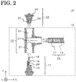
- FIG. 2 schematically shows the bus connection portion 10.
- the first electric apparatus 12 of the bus connection portion 10 includes a bus 14, a connector 15, and the bushing 11.
- the bus 14 and the bushing 11 are inserted into the connector 15, thus forming the first electric apparatus 12.
- the first electric apparatus 12 is connected via the bushing 11 to an electric apparatus in the housing 2 of the switching device 1.
- the bus 14 is formed by a bus conductor 16 and an insulation shield 17 surrounding the periphery of the bus conductor 16.
- the bushing 11 includes a first tightening portion 18 which is conductive, divided terminals 19, and a conductive member 20.
- the first tightening portion 18 is a stud bolt having external threads on both sides, for example.
- the bushing 11 is inserted into an opening 21 of the connector 15 in an arrow direction in FIG. 2 , and then the bus 14 is inserted into an opening 21 of the connector 15 in an arrow direction in FIG. 2 .
- the bus 14 is inserted into the connector 15, an end of the bus conductor 16 is held by the divided terminals 19 of the bushing 11, and a side surface of the bus conductor 16 is held by the conductive member 20.
- the second electric apparatus 13 includes an insulating plug 22, and for example, a ground apparatus (not shown).
- the insulating plug 22 serves to make insulation between the bus 14 and the second electric apparatus 13.
- the insulating plug 22 has, therein, a second tightening portion 23 which is conductive.
- the second tightening portion 23 has an internal thread to be fitted to the first tightening portion 18.
- the bus 14, the bushing 11, and the insulating plug 22 are inserted into the openings 21 of the connector 15, whereby the bus connection portion 10 is formed.
- the openings 21 of the connector 15 are closed by the bus 14, the insulating plug 22, and the bushing 11 that are inserted.
- gas is likely to remain between the insulating plug 22 and the connector 15. Gas present near the bus conductor 16 can be a cause of discharge during operation of the switching device 1, leading to insulation deterioration. Therefore, it is necessary to sufficiently exhaust the gas in assembling of the bus connection portion 10.
- FIG. 3(a) is a plan view of the exhaust tool 24 and FIG. 3(b) is a side view of the exhaust tool 24.
- the exhaust tool 24 has a bar-shaped body portion 25, a tip portion 26 provided at an end of the body portion 25, and a base portion 27 provided at another end opposite to the tip portion 26.
- a hole-shaped holding portion 28 is provided so as to penetrate in an X-axis direction in FIG. 3(a) , and at the end side, a cut-in portion 29 is provided adjacently to the holding portion 28.
- the cut-in portion 29 has a width approximately equal to or smaller than a short-side width (a Z-axis-direction width in FIG. 3(a) and FIG. 3(b) ) of the holding portion 28, and is cut in toward a tip end on the side where the tip portion 26 is provided in the exhaust tool 24.
- the cut-in portion 29 is formed in a valley-like shape by being cut in toward the inner side of the exhaust tool 24, i.e., toward the positive or negative direction of the X axis in FIG. 3(a) , and has a thin portion left at the bottom of the valley part.
- FIG. 4 shows a schematic plan view of the tip portion 26 of the exhaust tool 24, in which the tip portion 26 shown in FIG. 3 is enlarged.
- the tip portion 26 has the through-hole-shaped holding portion 28, and the cut-in portion 29 which is adjacent to the holding portion 28 and is not penetrated.
- the cut-in portion 29 is cut in along the long-side direction of the body portion 25 toward the end of the tip portion 26.
- the penetrated holding portion 28 is put so that the first tightening portion 18 passes therethrough, thereby restricting movement of the exhaust tool 24, and after an exhaust process, the exhaust tool 24 is drawn in a direction away from the first tightening portion 18, so that the cut-in portion 29 can be torn by the first tightening portion 18.
- displacement of the exhaust tool 24 is prevented and a gas passage is ensured, and the exhaust tool 24 can be taken out without leaving at least a part of the body portion 25 between the connection surfaces of an inner wall 30 of the connector 15 and an outer wall 31 of the insulating plug 22.
- the holding portion 28 is expanded toward the outer side of the exhaust tool 24, the expanded holding portion 28 is hooked on the first tightening portion 18 of the bushing 11 placed in the connector 15, and the body portion 25 of the exhaust tool 24 is brought into close contact with the inner wall 30 of the connector 15.
- the holding portion 28 holds the first tightening portion 18 so that movement of the exhaust tool 24 is restricted during assembly of the bus connection portion 10, and thus it is possible to efficiently exhaust the gas without obstructing the gas passage. Accordingly, while remaining of gas between the connector 15 and the insulating plug 22 is inhibited, connection between the first electric apparatus 12 and the second electric apparatus 13 can be made.
- the body portion 25 of the exhaust tool 24 is drawn from the connector 15, whereby force acts on the cut-in portion 29 so that the cut-in portion 29 can be torn by the first tightening portion 18.
- the cut-in portion 29 being severed, holding of the first tightening portion 18 by the holding portion 28 is released and the exhaust tool 24 can be pulled out from the first electric apparatus 12 without leaving gas therein.
- gas surrounded by the connector 15 and the insulating plug 22 is exhausted to the outside of the connector 15, and connection between the first electric apparatus 12 and the second electric apparatus 13 is completed while close contact between the inner wall 30 of the connector 15 and the outer wall 31 of the insulating plug 22 is kept.
- the tip width of the tip portion 26 is preferably tapered toward the tip end, as shown in FIG. 4 .
- insertion and extraction of the exhaust tool 24 are facilitated and a drawing force at the time of detachment is less likely to concentrate locally on the exhaust tool 24.
- the exhaust tool 24 can be prevented from being partially left inside the connector 15 and between the connection surfaces of the connector 15 and the insulating plug 22.
- FIG. 5 shows a schematic side view of the tip portion 26 of the exhaust tool 24, in which the tip portion 26 shown in FIG. 3 is enlarged.
- the thickness of the tip portion 26 preferably decreases toward the tip end.
- the tip portion 26 having such a shape provides effects that the exhaust tool 24 can be attached even to a narrow part and a drawing force at the time of detaching the exhaust tool 24 does not concentrate locally on the exhaust tool 24.
- a broken line in FIG. 5 represents the cut-in portion 29 seen through a side surface of the exhaust tool 24, and the cut-in portion 29 is provided adjacently to the holding portion 28 so as to have a thin portion remaining as shown by the broken line.
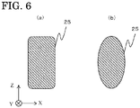
- FIG. 6 shows examples of a cross-section along line M-M in FIG. 3(a) , i.e., the sectional shape of the body portion 25.
- the sectional shape of the body portion 25 may be a rectangular shape with rounded corners as shown in FIG. 6(a) , or an oval shape as shown in FIG. 6(b) , for example.
- the oval shape includes a circle and an elliptic shape.
- the sectional shape may be a polygonal shape with rounded corners.
- FIG. 7 is an enlarged view of a part of the body portion 25.
- recesses 32 and projections 33 may be formed on the body portion 25.
- the recesses 32 and the projections 33 may be provided over a range from the body portion 25 to the tip portion 26 of the exhaust tool 24 so as to traverse in the short-side direction.
- the recesses 32 and the projections 33 may traverse over a partial range in the short-side direction instead of the entire range.
- the recesses 32 and the projections 33 may be provided on only one surface or on a plurality of surfaces.
- the recesses 32 and the projections 33 may be arranged in a dotted manner instead of traversing.
- FIG. 8(a) is a plan view of an exhaust tool 34 and FIG. 8(b) is a side view of the exhaust tool 34.
- the exhaust tool 34 according to embodiment 2 includes the bar-shaped body portion 25 and the tip portion 26 provided at the end of the body portion 25.
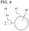
- FIG. 9 which is an enlarged view of the tip portion 26 in FIG. 8
- the tip portion 26 has the hole-shaped holding portion 28 through which the first tightening portion 18 can pass and which is provided so as to penetrate in the X-axis direction in FIG. 8 .
- the periphery of the holding portion 28 is surrounded by a support portion 35.
- the through-hole-shaped holding portion 28 and the support portion 35 supporting the holding portion 28 may be formed in various shapes such as a circle, a quadrangle with rounded corners, a triangle with rounded corners, and a rhombus with rounded corners as shown in FIG. 11 .
- the shape of the support portion 35 may be changed so as to be appropriate for insertion and extraction of the exhaust tool 34.
- the exhaust tool 34 having the through-hole-shaped holding portion 28, the cut-in portion 29 not penetrated, and the support portion 35 is used in assembly of the bus connection portion 10, whereby movement of the exhaust tool 34 is restricted and a gas passage is ensured while gas can be efficiently exhausted.
- the cut-in portion 29 is severed to separate the body portion 25 and the support portion 35, and thus the body portion 25 can be easily extracted. Therefore, the gas in the bus connection portion 10 can be assuredly exhausted.
- Embodiment 1 has shown the case where the sectional shape of the body portion 25 is a rectangular shape with rounded corners or an oval shape.
- sectional shapes shown in FIG. 12 may be employed. Each sectional shape in FIG. 12 corresponds to the sectional shape along line M-M in FIG. 3 or FIG. 8 .
- sectional shapes of the body portion 25 are shown in cells arranged in columns and rows. The features of the columns are as follows: in column 1, the outer shape is a quadrangular shape with rounded corners; in column 2, the outer shape is an oblong shape; in column 3, the outer shape is an elliptic shape; and in column 4, the outer shape is a rhombus.
- rows are as follows: in row A, there are no grooves on the surface; in row B, the upper and lower surfaces have grooves extending from the base portion 27 to the tip portion 26; in row C, one surface has a groove extending from the base portion 27 to the tip portion 26; and in row D, both side surfaces of the body portion 25 have grooves extending from the base portion 27 to the tip portion 26.
- the sectional shape of the body portion 25 can be selected from various shapes as shown in FIG. 12 .
- the sectional shape of the body portion 25 may be changed so as to be appropriate for insertion and extraction of the exhaust tool 24 or the exhaust tool 34. If the sectional shape of the body portion 25 is a polygonal shape, the contact areas where the surface of the body portion 25 contacts with the inner wall 30 and the outer wall 31 are increased as compared to a case where the surface of the body portion 25 has a curved shape, and therefore the body portion 25 can be prevented from being displaced so as to follow rotation of the insulating plug 22.
- the sectional shape of the body portion 25 is a rounded-corner shape or an oval shape, damage of the connector 15 and the insulating plug 22 can be prevented at the time of inserting/extracting the exhaust tool 24 or the exhaust tool 34. If the body portion 25 has a groove extending from the tip portion 26 to the base portion 27 as shown in rows B, C, D in FIG. 12 , a gap formed between the connection surfaces of the connector 15 and the insulating plug 22 when the exhaust tool 24 or the exhaust tool 34 is interposed, is enlarged. Thus, the gas remaining between the connector 15 and the insulating plug 22 can be sufficiently exhausted.
- the bus connection portion 10 of the switching device 1 shown in FIG. 1 includes at least parts of the first electric apparatus 12 and the second electric apparatus 13 as shown in FIG. 2 , the first electric apparatus 12 is composed of the bushing 11, the bus 14, and the connector 15, and the second electric apparatus 13 is composed of the insulating plug 22 and the ground apparatus (not shown) connected to the insulating plug 22.
- the first electric apparatus 12 is formed by inserting the bus 14 and the bushing 11 into the openings 21 of the connector 15.
- the bushing 11 is inserted into the opening 21 of the connector 15 so that one opening 21 is closed.
- the bus 14 is inserted into another opening 21 of the connector 15 so that the opening 21 is closed.
- the bushing 11 includes the first tightening portion 18, the divided terminal 19, and the conductive member 20.
- the bus 14 is formed by the bus conductor 16 and the insulation shield 17 surrounding the periphery thereof, and the bus conductor 16 is exposed at the end of the bus 14.
- the bus conductor 16 When the bus conductor 16 is inserted, the end of the inserted bus 14 is held from the upper and lower sides by the divided terminals 19 of the bushing 11, and the side part of the end of the bus 14 is supported by the conductive member 20.
- the bus 14 and the bushing 11 are electrically connected, so that another electric apparatus provided to the switching device 1 and connected to the bushing 11, and the first electric apparatus 12, are electrically connected. Since the openings 21 into which the bushing 11 and the bus 14 are inserted are closed, the gas passages are closed.
- the first tightening portion 18 provided in the bushing 11 protrudes inside the connector 15 toward the opening 21 of the connector 15 which is not closed by the bus 14 and the bushing 11.
- the first tightening portion 18 is, for example, a stud bolt having external threads on both sides, and the first tightening portion 18 and a tightening portion of another electric apparatus are fitted to each other, whereby the first electric apparatus 12 and the other electric apparatus are connected.
- the tightening portion of the other electric apparatus is the second tightening portion 23, and the other electric apparatus is the second electric apparatus 13.
- the second tightening portion 23 provided inside the insulating plug 22 and the first tightening portion 18 are fitted to each other, whereby the first electric apparatus 12 and the second electric apparatus 13 are connected.
- an insulating lubricant is applied to the connection surfaces of the inner wall 30 of the connector 15 and the outer wall 31 of the insulating plug 22 which are the connection surfaces of the first electric apparatus 12 and the second electric apparatus 13.
- grease is used as the lubricant.
- the exhaust tool 24 is placed in the opening 21 along the inner wall 30 of the connector 15, and the holding portion 28 of the exhaust tool 24 is put so that the first tightening portion 18 passes therethrough.
- the exhaust tool 24 is mounted in the opening 21.
- the holding portion 28 is pulled outward of the exhaust tool 24 to expand the through hole so that the first tightening portion 18 can be inserted into the holding portion 28.
- the divided terminal 19 connected to the bus 14 of the switching device 1 is provided inside the first electric apparatus 12.
- the first tightening portion 18 having an external thread on the outer circumference thereof is provided so as to protrude toward the second electric apparatus 13.
Landscapes
- Engineering & Computer Science (AREA)
- Manufacturing & Machinery (AREA)
- Power Engineering (AREA)
- Gas-Insulated Switchgears (AREA)
- Installation Of Bus-Bars (AREA)
- Connector Housings Or Holding Contact Members (AREA)
Abstract
Description
- The present disclosure relates to an exhaust tool used for assembly of a bus connection portion of a switching device used for grid operation of power receiving/distributing equipment or the like.
- In a switching device used for grid operation of power receiving/distributing equipment or the like, it is necessary to inhibit remaining of gas, for preventing reduction in insulation performance of the bus connection portion. Conventionally, in assembly of the bus connection portion, for example, a gas removing tool having an exhaust hole is inserted into the bus connection portion, and while a tightening member such as a screw is rotated, gas compressed in the bus connection portion is exhausted through the exhaust hole, thereby preventing remaining of the gas (see, for example, Patent Document 1).
- Patent Document 1:
WO2017/022618 - However, in a process when the gas removing tool is inserted between an insulating plug and a connector of the bus connection portion and the insulating plug is rotated and fitted into the connector, the gas removing tool moves so as to follow rotation of the insulating plug, so that the gas removing tool is displaced to hamper gas passage through the exhaust hole, thus causing a problem that the gas cannot be exhausted sufficiently.
- The present disclosure has been made to solve the above problem, and an object of the present disclosure is to provide an exhaust tool and a switching device manufacturing method using the exhaust tool that, in assembly of a bus connection portion of a switching device, prevent displacement of a tool used for exhausting gas, and efficiently exhaust gas between a connector and an insulating plug, thereby inhibiting remaining of the gas.
- An exhaust tool according to the present disclosure includes: a bar-shaped body portion; a tip portion provided at an end of the body portion; a through-hole-shaped holding portion which is provided at the tip portion and restricts movement of the body portion by being put so that a first tightening portion placed inside an insulating connector of a first electric apparatus having a bus and the connector passes through the holding portion; and a cut-in portion which is not penetrated and is cut in adjacently to the holding portion.
- A switching device manufacturing method according to the present disclosure includes the steps of: along an inner wall of an insulating connector provided to a first electric apparatus having a bus, putting the holding portion of the exhaust tool according to the present disclosure, so that a first tightening portion inside the connector connected to the bus passes through the holding portion; fitting the first tightening portion and a second tightening portion provided in an insulating plug of a second electric apparatus to each other and rotating the insulating plug with the body portion of the exhaust tool interposed between the inner wall of the connector and an outer wall of the insulating plug, so as to exhaust gas between the connector and the insulating plug through a gap formed by the body portion interposed between the connector and the insulating plug, and tighten the first tightening portion and the second tightening portion; and while drawing the exhaust tool from the connector, severing the cut-in portion of the exhaust tool and extracting the body portion from the connector.
- According to the present disclosure, by the through-hole-shaped holding portion, movement of the exhaust tool is restricted and a gas passage can be ensured, and by severing the cut-in portion not penetrated, the body portion of the exhaust tool can be extracted from the electric apparatus. Thus, gas can be efficiently exhausted while the bus connection portion is assembled.
-
- [
FIG. 1] FIG. 1 is a schematic view of a lateral side cross-section of a switching device according toembodiment 1. - [
FIG. 2] FIG. 2 is a schematic view of a bus connection portion according toembodiment 1. - [
FIG. 3] FIG. 3 shows a plan view and a side view of an exhaust tool according toembodiment 1. - [
FIG. 4] FIG. 4 is a schematic enlarged view of a tip portion of the exhaust tool according toembodiment 1. - [
FIG. 5] FIG. 5 is a schematic enlarged view of the tip portion of the exhaust tool according toembodiment 1. - [
FIG. 6] FIG. 6 shows sectional views of the exhaust tool according toembodiment 1, along line M-M inFIG. 3 . - [
FIG. 7] FIG. 7 is a schematic enlarged view of a part of a body portion of the exhaust tool according toembodiment 1. - [
FIG. 8] FIG. 8 shows a plan view and a side view of an exhaust tool according toembodiment 2. - [
FIG. 9] FIG. 9 is a schematic enlarged view of a tip portion of the exhaust tool according toembodiment 2. - [
FIG. 10] FIG. 10 is a schematic enlarged view of the tip portion of the exhaust tool according toembodiment 2. - [
FIG. 11] FIG. 11 shows plan views of a holding portion and a support portion according toembodiment 2. - [
FIG. 12] FIG. 12 shows schematic views of a cross-section of the exhaust tool according toembodiment 2. - [
FIG. 13] FIG. 13 illustrates an exhaust process according toembodiment 3. - Hereinafter,
embodiment 1 will be described with reference to the drawings. -
FIG. 1 is a schematic view of a lateral side cross-section of a switching device according toembodiment 1. InFIG. 1 , aswitching device 1 is a switchgear used for grid operation of power receiving/distributing equipment for power of an electrical substation, for example. In ahousing 2 of theswitching device 1, for example, adisconnector 3, adisconnector operation mechanism 4 as an operation mechanism therefor, a circuit breaker 5, a circuitbreaker operation mechanism 6 as an operation mechanism therefor, aground switch 7, an arrester 8, and a current transformer 9, are arranged. When abnormal current flows due to a lightning strike or the like, the circuit breaker 5 interrupts a circuit, to prevent the abnormal current from flowing through a grid and protect electric apparatuses connected to theswitching device 1. Theswitching device 1 is provided with abus connection portion 10, and in an example inFIG. 1 , thebus connection portion 10 is connected to abushing 11, which is then connected to thedisconnector 3 in thehousing 2. A firstelectric apparatus 12 and a secondelectric apparatus 13 described later are, at least partially, included in thebus connection portion 10. -
FIG. 2 schematically shows thebus connection portion 10. The firstelectric apparatus 12 of thebus connection portion 10 includes abus 14, aconnector 15, and thebushing 11. For example, thebus 14 and thebushing 11 are inserted into theconnector 15, thus forming the firstelectric apparatus 12. The firstelectric apparatus 12 is connected via thebushing 11 to an electric apparatus in thehousing 2 of theswitching device 1. Thebus 14 is formed by abus conductor 16 and aninsulation shield 17 surrounding the periphery of thebus conductor 16. Thebushing 11 includes a first tighteningportion 18 which is conductive, dividedterminals 19, and aconductive member 20. The first tighteningportion 18 is a stud bolt having external threads on both sides, for example. Thebushing 11 is inserted into anopening 21 of theconnector 15 in an arrow direction inFIG. 2 , and then thebus 14 is inserted into anopening 21 of theconnector 15 in an arrow direction inFIG. 2 . When thebus 14 is inserted into theconnector 15, an end of thebus conductor 16 is held by thedivided terminals 19 of thebushing 11, and a side surface of thebus conductor 16 is held by theconductive member 20. - The second
electric apparatus 13 includes aninsulating plug 22, and for example, a ground apparatus (not shown). Theinsulating plug 22 serves to make insulation between thebus 14 and the secondelectric apparatus 13. Theinsulating plug 22 has, therein, a second tighteningportion 23 which is conductive. Thesecond tightening portion 23 has an internal thread to be fitted to thefirst tightening portion 18. After thebushing 11 and thebus 14 are inserted into theconnector 15 in the arrow directions inFIG. 2 , theinsulating plug 22 is inserted into theconnector 15 in an arrow direction inFIG. 2 , and the first tighteningportion 18 and the second tighteningportion 23 are tightened, whereby thebus connection portion 10 is assembled. - As described above, the
bus 14, thebushing 11, and theinsulating plug 22 are inserted into theopenings 21 of theconnector 15, whereby thebus connection portion 10 is formed. In this case, theopenings 21 of theconnector 15 are closed by thebus 14, theinsulating plug 22, and thebushing 11 that are inserted. In particular, when theinsulating plug 22 is inserted after thebus 14 and thebushing 11 are inserted, gas is likely to remain between theinsulating plug 22 and theconnector 15. Gas present near thebus conductor 16 can be a cause of discharge during operation of theswitching device 1, leading to insulation deterioration. Therefore, it is necessary to sufficiently exhaust the gas in assembling of thebus connection portion 10. - Considering the above, the
bus connection portion 10 is assembled while gas is exhausted using anexhaust tool 24 shown inFIG. 3 according toembodiment 1.FIG. 3(a) is a plan view of theexhaust tool 24 andFIG. 3(b) is a side view of theexhaust tool 24. Theexhaust tool 24 has a bar-shaped body portion 25, atip portion 26 provided at an end of thebody portion 25, and abase portion 27 provided at another end opposite to thetip portion 26. In thetip portion 26, a hole-shaped holding portion 28 is provided so as to penetrate in an X-axis direction inFIG. 3(a) , and at the end side, a cut-inportion 29 is provided adjacently to theholding portion 28. The cut-inportion 29 has a width approximately equal to or smaller than a short-side width (a Z-axis-direction width inFIG. 3(a) and FIG. 3(b) ) of theholding portion 28, and is cut in toward a tip end on the side where thetip portion 26 is provided in theexhaust tool 24. The cut-inportion 29 is formed in a valley-like shape by being cut in toward the inner side of theexhaust tool 24, i.e., toward the positive or negative direction of the X axis inFIG. 3(a) , and has a thin portion left at the bottom of the valley part. -
FIG. 4 shows a schematic plan view of thetip portion 26 of theexhaust tool 24, in which thetip portion 26 shown inFIG. 3 is enlarged. Thetip portion 26 has the through-hole-shaped holding portion 28, and the cut-inportion 29 which is adjacent to theholding portion 28 and is not penetrated. InFIG. 4 , the cut-inportion 29 is cut in along the long-side direction of thebody portion 25 toward the end of thetip portion 26. By expanding the hole of the holdingportion 28, thefirst tightening portion 18 is allowed to pass through the holdingportion 28, and by tearing the cut-inportion 29, the holdingportion 28 can be released from thefirst tightening portion 18. That is, the penetrated holdingportion 28 is put so that thefirst tightening portion 18 passes therethrough, thereby restricting movement of theexhaust tool 24, and after an exhaust process, theexhaust tool 24 is drawn in a direction away from thefirst tightening portion 18, so that the cut-inportion 29 can be torn by thefirst tightening portion 18. Thus, displacement of theexhaust tool 24 is prevented and a gas passage is ensured, and theexhaust tool 24 can be taken out without leaving at least a part of thebody portion 25 between the connection surfaces of aninner wall 30 of theconnector 15 and anouter wall 31 of the insulatingplug 22. - Next, specific operation for assembling the
bus connection portion 10 using theexhaust tool 24 described above will be described. First, the holdingportion 28 is expanded toward the outer side of theexhaust tool 24, the expanded holdingportion 28 is hooked on thefirst tightening portion 18 of thebushing 11 placed in theconnector 15, and thebody portion 25 of theexhaust tool 24 is brought into close contact with theinner wall 30 of theconnector 15. - In a connection process for the
connector 15 and the insulatingplug 22, when theinner wall 30 of theconnector 15 and theouter wall 31 of the insulatingplug 22 are brought into contact with each other, gas surrounded by theconnector 15 and the insulatingplug 22 has no way to escape, and therefore remains between theconnector 15 and the insulatingplug 22. This gas is pressurized and compressed by the insulatingplug 22 being screwed to thefirst tightening portion 18 of thebushing 11. Here, between theinner wall 30 of theconnector 15 and the insulatingplug 22, theexhaust tool 24 whose movement is restricted by the holdingportion 28 is interposed and thus a gap is formed. With this gap, a gas passage is ensured and the pressurized gas is exhausted through the gap to the outside of theconnector 15. In addition, the holdingportion 28 holds thefirst tightening portion 18 so that movement of theexhaust tool 24 is restricted during assembly of thebus connection portion 10, and thus it is possible to efficiently exhaust the gas without obstructing the gas passage. Accordingly, while remaining of gas between theconnector 15 and the insulatingplug 22 is inhibited, connection between the firstelectric apparatus 12 and the secondelectric apparatus 13 can be made. - Further, shortly before connection between the
connector 15 and the insulatingplug 22 is completed, or after the completion, thebody portion 25 of theexhaust tool 24 is drawn from theconnector 15, whereby force acts on the cut-inportion 29 so that the cut-inportion 29 can be torn by thefirst tightening portion 18. By the cut-inportion 29 being severed, holding of thefirst tightening portion 18 by the holdingportion 28 is released and theexhaust tool 24 can be pulled out from the firstelectric apparatus 12 without leaving gas therein. Thus, gas surrounded by theconnector 15 and the insulatingplug 22 is exhausted to the outside of theconnector 15, and connection between the firstelectric apparatus 12 and the secondelectric apparatus 13 is completed while close contact between theinner wall 30 of theconnector 15 and theouter wall 31 of the insulatingplug 22 is kept. - Here, the tip width of the
tip portion 26 is preferably tapered toward the tip end, as shown inFIG. 4 . In a case of such a shape, insertion and extraction of theexhaust tool 24 are facilitated and a drawing force at the time of detachment is less likely to concentrate locally on theexhaust tool 24. Thus, theexhaust tool 24 can be prevented from being partially left inside theconnector 15 and between the connection surfaces of theconnector 15 and the insulatingplug 22. -
FIG. 5 shows a schematic side view of thetip portion 26 of theexhaust tool 24, in which thetip portion 26 shown inFIG. 3 is enlarged. As shown inFIG. 5 , the thickness of thetip portion 26 preferably decreases toward the tip end. Thetip portion 26 having such a shape provides effects that theexhaust tool 24 can be attached even to a narrow part and a drawing force at the time of detaching theexhaust tool 24 does not concentrate locally on theexhaust tool 24. A broken line inFIG. 5 represents the cut-inportion 29 seen through a side surface of theexhaust tool 24, and the cut-inportion 29 is provided adjacently to the holdingportion 28 so as to have a thin portion remaining as shown by the broken line. -
FIG. 6 shows examples of a cross-section along line M-M inFIG. 3(a) , i.e., the sectional shape of thebody portion 25. The sectional shape of thebody portion 25 may be a rectangular shape with rounded corners as shown inFIG. 6(a) , or an oval shape as shown inFIG. 6(b) , for example. Here, the oval shape includes a circle and an elliptic shape. Although not shown, the sectional shape may be a polygonal shape with rounded corners. Thus, by forming the sectional shape of thebody portion 25 as a rounded-corner shape, it becomes possible to exhaust gas without damaging theinner wall 30 of theconnector 15 and theouter wall 31 of the insulatingplug 22. In addition, even when the radial-direction dimensions of theconnector 15 and the insulatingplug 22 are small, a necessary strength can be ensured against an insertion/extraction force at the time of inserting/extracting theexhaust tool 24. -
FIG. 7 is an enlarged view of a part of thebody portion 25. As shown inFIG. 7 , recesses 32 andprojections 33 may be formed on thebody portion 25. For example, therecesses 32 and theprojections 33 may be provided over a range from thebody portion 25 to thetip portion 26 of theexhaust tool 24 so as to traverse in the short-side direction. Therecesses 32 and theprojections 33 may traverse over a partial range in the short-side direction instead of the entire range. Therecesses 32 and theprojections 33 may be provided on only one surface or on a plurality of surfaces. Therecesses 32 and theprojections 33 may be arranged in a dotted manner instead of traversing. - By providing the
recesses 32 and theprojections 33 as described above, it is possible to perform the exhaust process without hindering flow of an insulating lubricant such as paste or oil applied to theinner wall 30 of theconnector 15 and theouter wall 31 of the insulatingplug 22 at the time of connecting theconnector 15 and the insulatingplug 22. - The
exhaust tool 24 may be made from a flexible and lubricating material such as fluororesin, for example. Theexhaust tool 24 may be made from polypropylene resin, polyamide resin, polyether ether ketone resin, or polyacetal resin. Theexhaust tool 24 may be formed by impregnating a polyamide fiber with polypropylene resin. By using a composite material obtained by impregnating a reinforced fiber such as a polyamide fiber with resin, the strength can be ensured and thus damage and breakage are prevented when theexhaust tool 24 is extracted, whereby a part thereof can be prevented from being left between the connection surfaces of theinner wall 30 of theconnector 15 and theouter wall 31 of the insulatingplug 22. - For the
connector 15, for example, a deformable and restorable material such as silicone resin or ethylene propylene rubber may be used so that theexhaust tool 24 can be interposed between the connection surfaces of theinner wall 30 of theconnector 15 and theouter wall 31 of the insulatingplug 22. - As described above, the
exhaust tool 24 having the through-hole-shaped holdingportion 28 and the cut-inportion 29 not penetrated is used in assembly of thebus connection portion 10, whereby movement of theexhaust tool 24 is restricted and a gas passage is ensured while gas can be efficiently exhausted. After the gas is sufficiently exhausted, the cut-inportion 29 is severed and thus theexhaust tool 24 can be extracted. Therefore, the gas in thebus connection portion 10 can be assuredly exhausted. - The present embodiment has shown the case where the
connector 15 has theopenings 21 in three ways and one of theopenings 21 is closed by thebushing 11. However, without using thebushing 11, the connector may be configured such that theopenings 21 are provided in two ways with one opening closed and thefirst tightening portion 18 is provided inside. -
FIG. 8 shows an exhaust tool according toembodiment 2. The same components as inembodiment 1 are denoted by the same reference characters and the description thereof is omitted. - In
FIG. 8, FIG. 8(a) is a plan view of anexhaust tool 34 andFIG. 8(b) is a side view of theexhaust tool 34. Theexhaust tool 34 according toembodiment 2 includes the bar-shapedbody portion 25 and thetip portion 26 provided at the end of thebody portion 25. As shown inFIG. 9 which is an enlarged view of thetip portion 26 inFIG. 8 , thetip portion 26 has the hole-shaped holdingportion 28 through which thefirst tightening portion 18 can pass and which is provided so as to penetrate in the X-axis direction inFIG. 8 . The periphery of the holdingportion 28 is surrounded by asupport portion 35. Unlikeembodiment 1, it is not necessary to expand the hole in the short-side direction of theexhaust tool 34 so as to allow thefirst tightening portion 18 to pass therethrough. -
FIG. 9 shows a schematic plan view of thetip portion 26 of theexhaust tool 34, in which thetip portion 26 shown inFIG. 8 is enlarged. As shown inFIG. 9 , the cut-inportion 29 is provided between thebody portion 25 and thesupport portion 35. The cut-inportion 29 is provided at the outer edge of thesupport portion 35 adjacently to the holdingportion 28, and is cut in along the short-side direction of thebody portion 25. When thebody portion 25 and thesupport portion 35 are pulled in directions opposite to each other, the cut-inportion 29 not penetrated is torn and thus thebody portion 25 and thesupport portion 35 can be separated with the cut-inportion 29 as a boundary. -
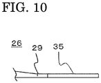
FIG. 10 shows a schematic side view of thetip portion 26 of theexhaust tool 34, in which thetip portion 26 shown inFIG. 8 is enlarged. Thetip portion 26 is formed such that the thickness thereof decreases toward the tip end, and the end of thetip portion 26 is thinnest. - In a case of assembling the
bus connection portion 10 using theexhaust tool 34, a lubricant is applied in advance to theinner wall 30 of theconnector 15 and theouter wall 31 of the insulatingplug 22 which are the connection surfaces of the firstelectric apparatus 12 and the secondelectric apparatus 13. Thereafter, the holdingportion 28 of theexhaust tool 34 is hooked on thefirst tightening portion 18 in the firstelectric apparatus 12, and thebody portion 25 of theexhaust tool 34 is brought into close contact with theinner wall 30 of the firstelectric apparatus 12, thus making preparation before assembly. - Then, as in
embodiment 1, the firstelectric apparatus 12 and the secondelectric apparatus 13 are assembled while positional displacement of theexhaust tool 34 is prevented by the holdingportion 28. Shortly before completion of the assembly, or after the completion, thebase portion 27 is pulled so as to draw theexhaust tool 34 from theconnector 15, whereby the cut-inportion 29 provided between thebody portion 25 and thesupport portion 35 of theexhaust tool 34 is torn and thebody portion 25 and thesupport portion 35 are separated. Thus, thebody portion 25 can be extracted to the outside of theconnector 15. Although thesupport portion 35 is left between the firstelectric apparatus 12 and the secondelectric apparatus 13, the surrounding space around thesupport portion 35 is at the same potential and therefore there is no electrical problem. - The through-hole-shaped holding
portion 28 and thesupport portion 35 supporting the holdingportion 28 may be formed in various shapes such as a circle, a quadrangle with rounded corners, a triangle with rounded corners, and a rhombus with rounded corners as shown inFIG. 11 . Thus, the shape of thesupport portion 35 may be changed so as to be appropriate for insertion and extraction of theexhaust tool 34. - For example, if the
support portion 35 has a polygonal shape, a frictional force acting on corners of thesupport portion 35 becomes smaller than in a case of having a shape with no corners, and thus the polygonal shape is more appropriate for insertion and extraction of theexhaust tool 34. If thesupport portion 35 has a rounded-corner shape or an elliptic shape including a circle, damage of theconnector 15 and the insulatingplug 22 can be prevented at the time of inserting/extracting theexhaust tool 34. - As described above, the
exhaust tool 34 having the through-hole-shaped holdingportion 28, the cut-inportion 29 not penetrated, and thesupport portion 35 is used in assembly of thebus connection portion 10, whereby movement of theexhaust tool 34 is restricted and a gas passage is ensured while gas can be efficiently exhausted. After the gas is sufficiently exhausted, the cut-inportion 29 is severed to separate thebody portion 25 and thesupport portion 35, and thus thebody portion 25 can be easily extracted. Therefore, the gas in thebus connection portion 10 can be assuredly exhausted. -
Embodiment 1 has shown the case where the sectional shape of thebody portion 25 is a rectangular shape with rounded corners or an oval shape. However, sectional shapes shown inFIG. 12 may be employed. Each sectional shape inFIG. 12 corresponds to the sectional shape along line M-M inFIG. 3 orFIG. 8 . InFIG. 12 , sectional shapes of thebody portion 25 are shown in cells arranged in columns and rows. The features of the columns are as follows: incolumn 1, the outer shape is a quadrangular shape with rounded corners; incolumn 2, the outer shape is an oblong shape; incolumn 3, the outer shape is an elliptic shape; and incolumn 4, the outer shape is a rhombus. The features of the rows are as follows: in row A, there are no grooves on the surface; in row B, the upper and lower surfaces have grooves extending from thebase portion 27 to thetip portion 26; in row C, one surface has a groove extending from thebase portion 27 to thetip portion 26; and in row D, both side surfaces of thebody portion 25 have grooves extending from thebase portion 27 to thetip portion 26. - The sectional shape of the
body portion 25 can be selected from various shapes as shown inFIG. 12 . Thus, the sectional shape of thebody portion 25 may be changed so as to be appropriate for insertion and extraction of theexhaust tool 24 or theexhaust tool 34. If the sectional shape of thebody portion 25 is a polygonal shape, the contact areas where the surface of thebody portion 25 contacts with theinner wall 30 and theouter wall 31 are increased as compared to a case where the surface of thebody portion 25 has a curved shape, and therefore thebody portion 25 can be prevented from being displaced so as to follow rotation of the insulatingplug 22. If the sectional shape of thebody portion 25 is a rounded-corner shape or an oval shape, damage of theconnector 15 and the insulatingplug 22 can be prevented at the time of inserting/extracting theexhaust tool 24 or theexhaust tool 34. If thebody portion 25 has a groove extending from thetip portion 26 to thebase portion 27 as shown in rows B, C, D inFIG. 12 , a gap formed between the connection surfaces of theconnector 15 and the insulatingplug 22 when theexhaust tool 24 or theexhaust tool 34 is interposed, is enlarged. Thus, the gas remaining between theconnector 15 and the insulatingplug 22 can be sufficiently exhausted. - With reference to
FIG. 13 , the exhaust process using theexhaust tool 24 according toembodiment 1 in manufacturing of theswitching device 1 will be described. Thebus connection portion 10 of theswitching device 1 shown inFIG. 1 includes at least parts of the firstelectric apparatus 12 and the secondelectric apparatus 13 as shown inFIG. 2 , the firstelectric apparatus 12 is composed of thebushing 11, thebus 14, and theconnector 15, and the secondelectric apparatus 13 is composed of the insulatingplug 22 and the ground apparatus (not shown) connected to the insulatingplug 22. - The first
electric apparatus 12 is formed by inserting thebus 14 and thebushing 11 into theopenings 21 of theconnector 15. Thebushing 11 is inserted into theopening 21 of theconnector 15 so that oneopening 21 is closed. After thebushing 11 is inserted, thebus 14 is inserted into anotheropening 21 of theconnector 15 so that theopening 21 is closed. Thebushing 11 includes thefirst tightening portion 18, the dividedterminal 19, and theconductive member 20. Thebus 14 is formed by thebus conductor 16 and theinsulation shield 17 surrounding the periphery thereof, and thebus conductor 16 is exposed at the end of thebus 14. When thebus conductor 16 is inserted, the end of the insertedbus 14 is held from the upper and lower sides by the dividedterminals 19 of thebushing 11, and the side part of the end of thebus 14 is supported by theconductive member 20. By contact with the dividedterminals 19 and theconductive member 20, thebus 14 and thebushing 11 are electrically connected, so that another electric apparatus provided to theswitching device 1 and connected to thebushing 11, and the firstelectric apparatus 12, are electrically connected. Since theopenings 21 into which thebushing 11 and thebus 14 are inserted are closed, the gas passages are closed. - In the first
electric apparatus 12, after the above connection process, thefirst tightening portion 18 provided in thebushing 11 protrudes inside theconnector 15 toward theopening 21 of theconnector 15 which is not closed by thebus 14 and thebushing 11. Thefirst tightening portion 18 is, for example, a stud bolt having external threads on both sides, and thefirst tightening portion 18 and a tightening portion of another electric apparatus are fitted to each other, whereby the firstelectric apparatus 12 and the other electric apparatus are connected. In the present embodiment, the tightening portion of the other electric apparatus is thesecond tightening portion 23, and the other electric apparatus is the secondelectric apparatus 13. Thesecond tightening portion 23 provided inside the insulatingplug 22 and thefirst tightening portion 18 are fitted to each other, whereby the firstelectric apparatus 12 and the secondelectric apparatus 13 are connected. - Next, with reference to
FIG. 13 , an exhaust procedure in the connection process for the firstelectric apparatus 12 and the secondelectric apparatus 13 will be described. In advance, an insulating lubricant is applied to the connection surfaces of theinner wall 30 of theconnector 15 and theouter wall 31 of the insulatingplug 22 which are the connection surfaces of the firstelectric apparatus 12 and the secondelectric apparatus 13. For example, grease is used as the lubricant. - Then, as shown in
FIG. 13 , theexhaust tool 24 is placed in theopening 21 along theinner wall 30 of theconnector 15, and the holdingportion 28 of theexhaust tool 24 is put so that thefirst tightening portion 18 passes therethrough. Thus, theexhaust tool 24 is mounted in theopening 21. In a case where theexhaust tool 24 having the holdingportion 28 in a closed state is used, the holdingportion 28 is pulled outward of theexhaust tool 24 to expand the through hole so that thefirst tightening portion 18 can be inserted into the holdingportion 28. - After the
exhaust tool 24 is mounted in theopening 21, theinner wall 30 of theconnector 15 provided to the firstelectric apparatus 12 and theouter wall 31 of the insulatingplug 22 provided to the secondelectric apparatus 13 are fitted to each other, so that theexhaust tool 24 is interposed between their connection surfaces. Here, theinner wall 30 and theouter wall 31 have such dimensions as to closely contact with each other when fitted. - Inside the insulating
plug 22, thesecond tightening portion 23 having an internal thread on the inner side is provided at one end in the direction of a drivingshaft 37. In addition, arotation member 39 for rotating the insulatingplug 22 is provided at the other end in the direction of the drivingshaft 37. Here, therotation member 39 has, for example, ahexagonal portion 40 for rotation, at an end thereof. By rotating the insulatingplug 22 using atorque wrench 36 having the drivingshaft 37 and asocket 38, the firstelectric apparatus 12 and the secondelectric apparatus 13 are connected. - Inside the first
electric apparatus 12, the divided terminal 19 connected to thebus 14 of theswitching device 1 is provided. At an end of the dividedterminal 19, thefirst tightening portion 18 having an external thread on the outer circumference thereof is provided so as to protrude toward the secondelectric apparatus 13. With the insulatingplug 22 inserted into theconnector 15, when the insulatingplug 22 is rotated in a direction A inFIG. 13 (clockwise direction as seen from the upper side of the torque wrench 36), the insulatingplug 22 is driven in a direction to be inserted into theconnector 15, so that thefirst tightening portion 18 and thesecond tightening portion 23 are tightened. - Through the process of inserting the insulating
plug 22, theinner wall 30 of theconnector 15 and theouter wall 31 of the insulatingplug 22 come close to each other and then closely contact with each other. Since theinner wall 30 of theconnector 15 and theouter wall 31 of the insulatingplug 22 closely contact with each other, gas present at the close-contact part is surrounded by theconnector 15 and the insulatingplug 22 and thus has no way to escape. - After the above process, the insulating
plug 22 is further rotated by thetorque wrench 36 so as to be screwed into theconnector 15, whereby the gas remaining between theconnector 15 and the insulatingplug 22 is compressed. As the insulatingplug 22 is rotated by thetorque wrench 36, the compressed gas moves in the circumferential direction of theouter wall 31 of the insulatingplug 22, so as to gather in the gap formed by theexhaust tool 24 interposed between theinner wall 30 of theconnector 15 and theouter wall 31 of the insulatingplug 22. The gas gathering in the gap is exhausted through the gap to the outside. - Then, shortly before connection of the first
electric apparatus 12 and the secondelectric apparatus 13 is completed, or after the completion, theexhaust tool 24 is drawn in a direction to be extracted from theconnector 15, i.e., a direction B inFIG. 13 . By the drawing force, the cut-inportion 29 of theexhaust tool 24 is torn, so that thebody portion 25 can be extracted. Then, after the cut-inportion 29 is severed, thebody portion 25 is extracted from theconnector 15, and thus connection between the firstelectric apparatus 12 and the secondelectric apparatus 13 is completed while close contact between theinner wall 30 of theconnector 15 and theouter wall 31 of the insulatingplug 22 is kept. - That is, the
exhaust tool 24 is placed along theinner wall 30 of theconnector 15, and the through-hole-shaped holdingportion 28 is put so that thefirst tightening portion 18 inside theconnector 15 passes therethrough. Then, thefirst tightening portion 18 and thesecond tightening portion 23 are fitted to each other and the insulatingplug 22 is rotated with thebody portion 25 interposed between theinner wall 30 of theconnector 15 and theouter wall 31 of the insulatingplug 22, so that gas between theconnector 15 and the insulatingplug 22 is exhausted through a gap formed by thebody portion 25 interposed between the insulatingplug 22 and theconnector 15, and thefirst tightening portion 18 and thesecond tightening portion 23 are tightened. Then, while theexhaust tool 24 is drawn from theconnector 15, the cut-inportion 29 is severed and thebody portion 25 is extracted from theconnector 15. Thus, it is possible to efficiently exhaust gas while assembling thebus connection portion 10 provided to theswitching device 1. - The present embodiment has shown the case of using the
exhaust tool 24 according toembodiment 1. However, the same effects can be obtained even in a case of using theexhaust tool 34 described inembodiment 2 to perform the exhaust process in manufacturing of theswitching device 1. In this case, in the process of drawing theexhaust tool 34, thesupport portion 35 and thebody portion 25 are separated and thesupport portion 35 is left in theconnector 15. -
Embodiments 1 to 3 have shown the case of connecting the firstelectric apparatus 12 and the secondelectric apparatus 13, but may be applied to another electric apparatus in theswitching device 1 or an external electric apparatus connected to theswitching device 1. - It is noted that, within the scope of the present disclosure, the embodiments described in the present disclosure may be freely combined with each other, or each of the embodiments may be modified or simplified as appropriate.
-
- 1
- switching device
- 2
- housing
- 3
- disconnector
- 4
- disconnector operation mechanism
- 5
- circuit breaker
- 6
- circuit breaker operation mechanism
- 7
- ground switch
- 8
- arrester
- 9
- current transformer
- 10
- bus connection portion
- 11
- bushing
- 12
- first electric apparatus
- 13
- second electric apparatus
- 14
- bus
- 15
- connector
- 16
- bus conductor
- 17
- insulation shield
- 18
- first tightening portion
- 19
- divided terminal
- 20
- conductive member
- 21
- opening
- 22
- insulating plug
- 23
- second tightening portion
- 24, 34
- exhaust tool
- 25
- body portion
- 26
- tip portion
- 27
- base portion
- 28
- holding portion
- 29
- cut-in portion
- 30
- inner wall
- 31
- outer wall
- 32
- recess
- 33
- projection
- 35
- support portion
- 36
- torque wrench
- 37
- driving shaft
- 38
- socket
- 39
- rotation member
- 40
- hexagonal portion
Claims (10)
- An exhaust tool comprising:a bar-shaped body portion;a tip portion provided at an end of the body portion;a through-hole-shaped holding portion which is provided at the tip portion and restricts movement of the body portion by being put so that a first tightening portion placed inside an insulating connector of a first electric apparatus having a bus and the connector passes through the holding portion; anda cut-in portion which is not penetrated and is cut in adjacently to the holding portion.
- The exhaust tool according to claim 1, wherein
the cut-in portion is cut in along a long-side direction of the body portion. - The exhaust tool according to claim 1, whereinthe holding portion is provided so as to be surrounded by a support portion, andthe cut-in portion is cut in along a short-side direction of the body portion, between the support portion and the body portion.
- The exhaust tool according to claim 3, wherein
the holding portion is a through hole having a polygonal or circular sectional shape. - The exhaust tool according to any one of claims 1 to 4, wherein
the sectional shape of the body portion is a polygonal shape with rounded corners, or an oval shape. - The exhaust tool according to any one of claims 1 to 5, wherein
the body portion has recesses and projections on at least one surface thereof. - The exhaust tool according to any one of claims 1 to 6, wherein
the body portion has a groove along a long-side direction thereof. - The exhaust tool according to any one of claims 1 to 7, wherein
the body portion is made of flexible resin. - The exhaust tool according to any one of claims 1 to 8, wherein
at least one of a thickness and a width of the tip portion decreases toward a tip end. - A switching device manufacturing method comprising the steps of:along an inner wall of an insulating connector provided to a first electric apparatus having a bus, putting the holding portion of the exhaust tool according to any one of claims 1 to 9, so that a first tightening portion inside the connector connected to the bus passes through the holding portion;fitting the first tightening portion and a second tightening portion provided in an insulating plug of a second electric apparatus to each other and rotating the insulating plug with the body portion of the exhaust tool interposed between the inner wall of the connector and an outer wall of the insulating plug, so as to exhaust gas between the connector and the insulating plug through a gap formed by the body portion interposed between the connector and the insulating plug, and tighten the first tightening portion and the second tightening portion; andwhile drawing the exhaust tool from the connector, severing the cut-in portion of the exhaust tool and extracting the body portion from the connector.
Applications Claiming Priority (1)
| Application Number | Priority Date | Filing Date | Title |
|---|---|---|---|
| PCT/JP2019/025583 WO2020261482A1 (en) | 2019-06-27 | 2019-06-27 | Exhaust tool and method for manufacturing switching device using same |
Publications (3)
| Publication Number | Publication Date |
|---|---|
| EP3993192A1 true EP3993192A1 (en) | 2022-05-04 |
| EP3993192A4 EP3993192A4 (en) | 2022-06-22 |
| EP3993192B1 EP3993192B1 (en) | 2025-01-22 |
Family
ID=74061590
Family Applications (1)
| Application Number | Title | Priority Date | Filing Date |
|---|---|---|---|
| EP19934674.3A Active EP3993192B1 (en) | 2019-06-27 | 2019-06-27 | Exhaust tool and method for manufacturing a switching device using such tool |
Country Status (5)
| Country | Link |
|---|---|
| EP (1) | EP3993192B1 (en) |
| JP (1) | JP7142782B2 (en) |
| CN (1) | CN114026754B (en) |
| TW (1) | TWI719739B (en) |
| WO (1) | WO2020261482A1 (en) |
Cited By (1)
| Publication number | Priority date | Publication date | Assignee | Title |
|---|---|---|---|---|
| US20220006270A1 (en) * | 2018-12-26 | 2022-01-06 | Mitsubishi Electric Corporation | Busbar connecting device |
Families Citing this family (1)
| Publication number | Priority date | Publication date | Assignee | Title |
|---|---|---|---|---|
| CN119340874B (en) * | 2024-11-14 | 2025-07-18 | 长园电力技术有限公司 | A cable joint installation exhaust device |
Family Cites Families (10)
| Publication number | Priority date | Publication date | Assignee | Title |
|---|---|---|---|---|
| JP3350419B2 (en) * | 1997-09-30 | 2002-11-25 | 昭和電線電纜株式会社 | T type bushing |
| JPH11164413A (en) * | 1997-12-01 | 1999-06-18 | Toshiba Corp | Insulated busbar device |
| JP3624779B2 (en) * | 2000-02-24 | 2005-03-02 | 株式会社日立製作所 | Gas insulated switchgear and method of assembling the same |
| JP2002345131A (en) * | 2001-05-15 | 2002-11-29 | Mitsubishi Electric Corp | Busbar connection device for gas insulated switchgear |
| JP4879936B2 (en) * | 2008-06-18 | 2012-02-22 | 三菱電機株式会社 | Gas filling inspection apparatus and gas leakage inspection method |
| JP5496522B2 (en) * | 2009-03-02 | 2014-05-21 | 三洋電機株式会社 | Battery system |
| EP2501002B1 (en) * | 2011-03-15 | 2014-11-26 | ABB Technology AG | Diagonal demounting module for a switchgear |
| WO2017022618A1 (en) * | 2015-07-31 | 2017-02-09 | 三菱電機株式会社 | Deaeration tool, and switch gear electrical apparatus manufacturing method using deaeration tool |
| EP3644466B1 (en) * | 2017-06-20 | 2021-04-28 | Mitsubishi Electric Corporation | Electrical-device connecting apparatus and opening/closing apparatus |
| CN207994556U (en) * | 2018-04-03 | 2018-10-19 | 李政 | A kind of novel top bus-bar system |
-
2019
- 2019-06-27 EP EP19934674.3A patent/EP3993192B1/en active Active
- 2019-06-27 CN CN201980097736.6A patent/CN114026754B/en active Active
- 2019-06-27 WO PCT/JP2019/025583 patent/WO2020261482A1/en not_active Ceased
- 2019-06-27 JP JP2021528780A patent/JP7142782B2/en active Active
- 2019-12-04 TW TW108144240A patent/TWI719739B/en active
Cited By (2)
| Publication number | Priority date | Publication date | Assignee | Title |
|---|---|---|---|---|
| US20220006270A1 (en) * | 2018-12-26 | 2022-01-06 | Mitsubishi Electric Corporation | Busbar connecting device |
| US11658467B2 (en) * | 2018-12-26 | 2023-05-23 | Mitsubishi Electric Corporation | Busbar connecting device |
Also Published As
| Publication number | Publication date |
|---|---|
| JP7142782B2 (en) | 2022-09-27 |
| EP3993192A4 (en) | 2022-06-22 |
| EP3993192B1 (en) | 2025-01-22 |
| CN114026754B (en) | 2024-07-19 |
| JPWO2020261482A1 (en) | 2020-12-30 |
| WO2020261482A1 (en) | 2020-12-30 |
| TWI719739B (en) | 2021-02-21 |
| CN114026754A (en) | 2022-02-08 |
| TW202100860A (en) | 2021-01-01 |
Similar Documents
| Publication | Publication Date | Title |
|---|---|---|
| EP3993192B1 (en) | Exhaust tool and method for manufacturing a switching device using such tool | |
| US20090255106A1 (en) | Method of using an extender for a separable insulated connector | |
| EP3905460A1 (en) | Busbar connecting device | |
| JP3644264B2 (en) | Gas insulated switchgear and method for disassembling the same | |
| CN106463881B (en) | Replaceable bushing for electrical equipment | |
| US11417973B2 (en) | Connector assembly for connection to a vehicle electrical ground | |
| EP1649554B1 (en) | An electrical connection device | |
| US20190319224A1 (en) | Recloser battery assembly | |
| KR101214604B1 (en) | Safety of capacitor | |
| US11056862B2 (en) | Electrical device connector and switchgear | |
| US7897275B2 (en) | Electrical rechargeable battery | |
| KR102602574B1 (en) | Device for connecting ground wire of lightning arrester | |
| HK40066129A (en) | Exhaust tool and method for manufacturing switching device using same | |
| WO2020009977A1 (en) | Smart split washer cable gland entry | |
| CN207265623U (en) | A kind of removable arrester | |
| KR101091122B1 (en) | Stud connector | |
| JP3886565B2 (en) | Cable head with disconnect function | |
| CN214411665U (en) | Can realize insulating jump clamp of stable connection | |
| JPH1023650A (en) | Machine direct-coupled cable head | |
| US20240071695A1 (en) | Terminal for auxiliary contact | |
| EP4160835A1 (en) | Bus connection device | |
| RU180980U1 (en) | HIGH VOLTAGE FUSE UNIT DEVICE | |
| KR200299567Y1 (en) | The connecting apparatus of subterranean low pressure cable | |
| JP2024037099A (en) | Power cable connection parts, power cable connection structure, and power cable connection method | |
| KR100591537B1 (en) | Fuel Pump Connector |
Legal Events
| Date | Code | Title | Description |
|---|---|---|---|
| STAA | Information on the status of an ep patent application or granted ep patent |
Free format text: STATUS: THE INTERNATIONAL PUBLICATION HAS BEEN MADE |
|
| PUAI | Public reference made under article 153(3) epc to a published international application that has entered the european phase |
Free format text: ORIGINAL CODE: 0009012 |
|
| STAA | Information on the status of an ep patent application or granted ep patent |
Free format text: STATUS: REQUEST FOR EXAMINATION WAS MADE |
|
| 17P | Request for examination filed |
Effective date: 20211006 |
|
| AK | Designated contracting states |
Kind code of ref document: A1 Designated state(s): AL AT BE BG CH CY CZ DE DK EE ES FI FR GB GR HR HU IE IS IT LI LT LU LV MC MK MT NL NO PL PT RO RS SE SI SK SM TR |
|
| A4 | Supplementary search report drawn up and despatched |
Effective date: 20220524 |
|
| RIC1 | Information provided on ipc code assigned before grant |
Ipc: H02B 13/00 20060101ALN20220518BHEP Ipc: H02B 3/00 20060101AFI20220518BHEP |
|
| DAV | Request for validation of the european patent (deleted) | ||
| DAX | Request for extension of the european patent (deleted) | ||
| RIC1 | Information provided on ipc code assigned before grant |
Ipc: H02B 13/00 20060101ALN20240717BHEP Ipc: H02B 3/00 20060101AFI20240717BHEP |
|
| RIC1 | Information provided on ipc code assigned before grant |
Ipc: H02B 13/00 20060101ALN20240719BHEP Ipc: H02B 3/00 20060101AFI20240719BHEP |
|
| GRAP | Despatch of communication of intention to grant a patent |
Free format text: ORIGINAL CODE: EPIDOSNIGR1 |
|
| STAA | Information on the status of an ep patent application or granted ep patent |
Free format text: STATUS: GRANT OF PATENT IS INTENDED |
|
| RIC1 | Information provided on ipc code assigned before grant |
Ipc: H02B 13/00 20060101ALN20240805BHEP Ipc: H02B 3/00 20060101AFI20240805BHEP |
|
| INTG | Intention to grant announced |
Effective date: 20240902 |
|
| GRAS | Grant fee paid |
Free format text: ORIGINAL CODE: EPIDOSNIGR3 |
|
| GRAA | (expected) grant |
Free format text: ORIGINAL CODE: 0009210 |
|
| STAA | Information on the status of an ep patent application or granted ep patent |
Free format text: STATUS: THE PATENT HAS BEEN GRANTED |
|
| AK | Designated contracting states |
Kind code of ref document: B1 Designated state(s): AL AT BE BG CH CY CZ DE DK EE ES FI FR GB GR HR HU IE IS IT LI LT LU LV MC MK MT NL NO PL PT RO RS SE SI SK SM TR |
|
| REG | Reference to a national code |
Ref country code: GB Ref legal event code: FG4D |
|
| REG | Reference to a national code |
Ref country code: CH Ref legal event code: EP |
|
| REG | Reference to a national code |
Ref country code: IE Ref legal event code: FG4D |
|
| REG | Reference to a national code |
Ref country code: DE Ref legal event code: R096 Ref document number: 602019065286 Country of ref document: DE |
|
| REG | Reference to a national code |
Ref country code: NL Ref legal event code: MP Effective date: 20250122 |
|
| PG25 | Lapsed in a contracting state [announced via postgrant information from national office to epo] |
Ref country code: NL Free format text: LAPSE BECAUSE OF FAILURE TO SUBMIT A TRANSLATION OF THE DESCRIPTION OR TO PAY THE FEE WITHIN THE PRESCRIBED TIME-LIMIT Effective date: 20250122 |
|
| PG25 | Lapsed in a contracting state [announced via postgrant information from national office to epo] |
Ref country code: RS Free format text: LAPSE BECAUSE OF FAILURE TO SUBMIT A TRANSLATION OF THE DESCRIPTION OR TO PAY THE FEE WITHIN THE PRESCRIBED TIME-LIMIT Effective date: 20250422 |
|
| PG25 | Lapsed in a contracting state [announced via postgrant information from national office to epo] |
Ref country code: FI Free format text: LAPSE BECAUSE OF FAILURE TO SUBMIT A TRANSLATION OF THE DESCRIPTION OR TO PAY THE FEE WITHIN THE PRESCRIBED TIME-LIMIT Effective date: 20250122 |
|
| PG25 | Lapsed in a contracting state [announced via postgrant information from national office to epo] |
Ref country code: PL Free format text: LAPSE BECAUSE OF FAILURE TO SUBMIT A TRANSLATION OF THE DESCRIPTION OR TO PAY THE FEE WITHIN THE PRESCRIBED TIME-LIMIT Effective date: 20250122 |
|
| PGFP | Annual fee paid to national office [announced via postgrant information from national office to epo] |
Ref country code: DE Payment date: 20250429 Year of fee payment: 7 |
|
| PG25 | Lapsed in a contracting state [announced via postgrant information from national office to epo] |
Ref country code: ES Free format text: LAPSE BECAUSE OF FAILURE TO SUBMIT A TRANSLATION OF THE DESCRIPTION OR TO PAY THE FEE WITHIN THE PRESCRIBED TIME-LIMIT Effective date: 20250122 |
|
| REG | Reference to a national code |
Ref country code: LT Ref legal event code: MG9D |
|
| PG25 | Lapsed in a contracting state [announced via postgrant information from national office to epo] |
Ref country code: IS Free format text: LAPSE BECAUSE OF FAILURE TO SUBMIT A TRANSLATION OF THE DESCRIPTION OR TO PAY THE FEE WITHIN THE PRESCRIBED TIME-LIMIT Effective date: 20250522 Ref country code: NO Free format text: LAPSE BECAUSE OF FAILURE TO SUBMIT A TRANSLATION OF THE DESCRIPTION OR TO PAY THE FEE WITHIN THE PRESCRIBED TIME-LIMIT Effective date: 20250422 |
|
| REG | Reference to a national code |
Ref country code: AT Ref legal event code: MK05 Ref document number: 1762191 Country of ref document: AT Kind code of ref document: T Effective date: 20250122 |
|
| PG25 | Lapsed in a contracting state [announced via postgrant information from national office to epo] |
Ref country code: HR Free format text: LAPSE BECAUSE OF FAILURE TO SUBMIT A TRANSLATION OF THE DESCRIPTION OR TO PAY THE FEE WITHIN THE PRESCRIBED TIME-LIMIT Effective date: 20250122 |
|
| PG25 | Lapsed in a contracting state [announced via postgrant information from national office to epo] |
Ref country code: LV Free format text: LAPSE BECAUSE OF FAILURE TO SUBMIT A TRANSLATION OF THE DESCRIPTION OR TO PAY THE FEE WITHIN THE PRESCRIBED TIME-LIMIT Effective date: 20250122 Ref country code: PT Free format text: LAPSE BECAUSE OF FAILURE TO SUBMIT A TRANSLATION OF THE DESCRIPTION OR TO PAY THE FEE WITHIN THE PRESCRIBED TIME-LIMIT Effective date: 20250522 |
|
| PGFP | Annual fee paid to national office [announced via postgrant information from national office to epo] |
Ref country code: FR Payment date: 20250508 Year of fee payment: 7 |
|
| PG25 | Lapsed in a contracting state [announced via postgrant information from national office to epo] |
Ref country code: BG Free format text: LAPSE BECAUSE OF FAILURE TO SUBMIT A TRANSLATION OF THE DESCRIPTION OR TO PAY THE FEE WITHIN THE PRESCRIBED TIME-LIMIT Effective date: 20250122 Ref country code: GR Free format text: LAPSE BECAUSE OF FAILURE TO SUBMIT A TRANSLATION OF THE DESCRIPTION OR TO PAY THE FEE WITHIN THE PRESCRIBED TIME-LIMIT Effective date: 20250423 |
|
| PG25 | Lapsed in a contracting state [announced via postgrant information from national office to epo] |
Ref country code: AT Free format text: LAPSE BECAUSE OF FAILURE TO SUBMIT A TRANSLATION OF THE DESCRIPTION OR TO PAY THE FEE WITHIN THE PRESCRIBED TIME-LIMIT Effective date: 20250122 |
|
| PG25 | Lapsed in a contracting state [announced via postgrant information from national office to epo] |
Ref country code: SE Free format text: LAPSE BECAUSE OF FAILURE TO SUBMIT A TRANSLATION OF THE DESCRIPTION OR TO PAY THE FEE WITHIN THE PRESCRIBED TIME-LIMIT Effective date: 20250122 |
|
| P01 | Opt-out of the competence of the unified patent court (upc) registered |
Free format text: CASE NUMBER: UPC_APP_4938_3993192/2025 Effective date: 20250827 |
|
| PG25 | Lapsed in a contracting state [announced via postgrant information from national office to epo] |
Ref country code: SM Free format text: LAPSE BECAUSE OF FAILURE TO SUBMIT A TRANSLATION OF THE DESCRIPTION OR TO PAY THE FEE WITHIN THE PRESCRIBED TIME-LIMIT Effective date: 20250122 |
|
| PG25 | Lapsed in a contracting state [announced via postgrant information from national office to epo] |
Ref country code: DK Free format text: LAPSE BECAUSE OF FAILURE TO SUBMIT A TRANSLATION OF THE DESCRIPTION OR TO PAY THE FEE WITHIN THE PRESCRIBED TIME-LIMIT Effective date: 20250122 |
|
| PG25 | Lapsed in a contracting state [announced via postgrant information from national office to epo] |
Ref country code: IT Free format text: LAPSE BECAUSE OF FAILURE TO SUBMIT A TRANSLATION OF THE DESCRIPTION OR TO PAY THE FEE WITHIN THE PRESCRIBED TIME-LIMIT Effective date: 20250122 |
|
| PG25 | Lapsed in a contracting state [announced via postgrant information from national office to epo] |
Ref country code: EE Free format text: LAPSE BECAUSE OF FAILURE TO SUBMIT A TRANSLATION OF THE DESCRIPTION OR TO PAY THE FEE WITHIN THE PRESCRIBED TIME-LIMIT Effective date: 20250122 Ref country code: CZ Free format text: LAPSE BECAUSE OF FAILURE TO SUBMIT A TRANSLATION OF THE DESCRIPTION OR TO PAY THE FEE WITHIN THE PRESCRIBED TIME-LIMIT Effective date: 20250122 |
|
| REG | Reference to a national code |
Ref country code: DE Ref legal event code: R097 Ref document number: 602019065286 Country of ref document: DE |
|
| PG25 | Lapsed in a contracting state [announced via postgrant information from national office to epo] |
Ref country code: RO Free format text: LAPSE BECAUSE OF FAILURE TO SUBMIT A TRANSLATION OF THE DESCRIPTION OR TO PAY THE FEE WITHIN THE PRESCRIBED TIME-LIMIT Effective date: 20250122 |
|
| PG25 | Lapsed in a contracting state [announced via postgrant information from national office to epo] |
Ref country code: SK Free format text: LAPSE BECAUSE OF FAILURE TO SUBMIT A TRANSLATION OF THE DESCRIPTION OR TO PAY THE FEE WITHIN THE PRESCRIBED TIME-LIMIT Effective date: 20250122 |
|
| PLBE | No opposition filed within time limit |
Free format text: ORIGINAL CODE: 0009261 |
|
| STAA | Information on the status of an ep patent application or granted ep patent |
Free format text: STATUS: NO OPPOSITION FILED WITHIN TIME LIMIT |
|
| REG | Reference to a national code |
Ref country code: CH Ref legal event code: L10 Free format text: ST27 STATUS EVENT CODE: U-0-0-L10-L00 (AS PROVIDED BY THE NATIONAL OFFICE) Effective date: 20251203 |
|
| 26N | No opposition filed |
Effective date: 20251023 |
|
| REG | Reference to a national code |
Ref country code: CH Ref legal event code: H13 Free format text: ST27 STATUS EVENT CODE: U-0-0-H10-H13 (AS PROVIDED BY THE NATIONAL OFFICE) Effective date: 20260127 |
|
| PG25 | Lapsed in a contracting state [announced via postgrant information from national office to epo] |
Ref country code: MC Free format text: LAPSE BECAUSE OF FAILURE TO SUBMIT A TRANSLATION OF THE DESCRIPTION OR TO PAY THE FEE WITHIN THE PRESCRIBED TIME-LIMIT Effective date: 20250122 |
|
| PG25 | Lapsed in a contracting state [announced via postgrant information from national office to epo] |
Ref country code: LU Free format text: LAPSE BECAUSE OF NON-PAYMENT OF DUE FEES Effective date: 20250627 |
|
| GBPC | Gb: european patent ceased through non-payment of renewal fee |
Effective date: 20250627 |
|
| REG | Reference to a national code |
Ref country code: BE Ref legal event code: MM Effective date: 20250630 |
|
| PG25 | Lapsed in a contracting state [announced via postgrant information from national office to epo] |
Ref country code: GB Free format text: LAPSE BECAUSE OF NON-PAYMENT OF DUE FEES Effective date: 20250627 |
|
| PG25 | Lapsed in a contracting state [announced via postgrant information from national office to epo] |
Ref country code: IE Free format text: LAPSE BECAUSE OF NON-PAYMENT OF DUE FEES Effective date: 20250627 |
|
| PG25 | Lapsed in a contracting state [announced via postgrant information from national office to epo] |
Ref country code: BE Free format text: LAPSE BECAUSE OF NON-PAYMENT OF DUE FEES Effective date: 20250630 |
|
| PG25 | Lapsed in a contracting state [announced via postgrant information from national office to epo] |
Ref country code: CH Free format text: LAPSE BECAUSE OF NON-PAYMENT OF DUE FEES Effective date: 20250630 |