EP3993179A1 - Charging gun and strain relief structure thereof - Google Patents
Charging gun and strain relief structure thereof Download PDFInfo
- Publication number
- EP3993179A1 EP3993179A1 EP21181770.5A EP21181770A EP3993179A1 EP 3993179 A1 EP3993179 A1 EP 3993179A1 EP 21181770 A EP21181770 A EP 21181770A EP 3993179 A1 EP3993179 A1 EP 3993179A1
- Authority
- EP
- European Patent Office
- Prior art keywords
- case
- strain relief
- relief structure
- assembled
- protrusions
- Prior art date
- Legal status (The legal status is an assumption and is not a legal conclusion. Google has not performed a legal analysis and makes no representation as to the accuracy of the status listed.)
- Granted
Links
Images



Classifications
-
- H—ELECTRICITY
- H01—ELECTRIC ELEMENTS
- H01R—ELECTRICALLY-CONDUCTIVE CONNECTIONS; STRUCTURAL ASSOCIATIONS OF A PLURALITY OF MUTUALLY-INSULATED ELECTRICAL CONNECTING ELEMENTS; COUPLING DEVICES; CURRENT COLLECTORS
- H01R13/00—Details of coupling devices of the kinds covered by groups H01R12/70 or H01R24/00 - H01R33/00
- H01R13/58—Means for relieving strain on wire connection, e.g. cord grip, for avoiding loosening of connections between wires and terminals within a coupling device terminating a cable
- H01R13/5804—Means for relieving strain on wire connection, e.g. cord grip, for avoiding loosening of connections between wires and terminals within a coupling device terminating a cable comprising a separate cable clamping part
- H01R13/5812—Means for relieving strain on wire connection, e.g. cord grip, for avoiding loosening of connections between wires and terminals within a coupling device terminating a cable comprising a separate cable clamping part the cable clamping being achieved by mounting the separate part on the housing of the coupling device
-
- H—ELECTRICITY
- H01—ELECTRIC ELEMENTS
- H01R—ELECTRICALLY-CONDUCTIVE CONNECTIONS; STRUCTURAL ASSOCIATIONS OF A PLURALITY OF MUTUALLY-INSULATED ELECTRICAL CONNECTING ELEMENTS; COUPLING DEVICES; CURRENT COLLECTORS
- H01R13/00—Details of coupling devices of the kinds covered by groups H01R12/70 or H01R24/00 - H01R33/00
- H01R13/46—Bases; Cases
- H01R13/502—Bases; Cases composed of different pieces
-
- B—PERFORMING OPERATIONS; TRANSPORTING
- B60—VEHICLES IN GENERAL
- B60L—PROPULSION OF ELECTRICALLY-PROPELLED VEHICLES; SUPPLYING ELECTRIC POWER FOR AUXILIARY EQUIPMENT OF ELECTRICALLY-PROPELLED VEHICLES; ELECTRODYNAMIC BRAKE SYSTEMS FOR VEHICLES IN GENERAL; MAGNETIC SUSPENSION OR LEVITATION FOR VEHICLES; MONITORING OPERATING VARIABLES OF ELECTRICALLY-PROPELLED VEHICLES; ELECTRIC SAFETY DEVICES FOR ELECTRICALLY-PROPELLED VEHICLES
- B60L53/00—Methods of charging batteries, specially adapted for electric vehicles; Charging stations or on-board charging equipment therefor; Exchange of energy storage elements in electric vehicles
- B60L53/10—Methods of charging batteries, specially adapted for electric vehicles; Charging stations or on-board charging equipment therefor; Exchange of energy storage elements in electric vehicles characterised by the energy transfer between the charging station and the vehicle
- B60L53/14—Conductive energy transfer
- B60L53/16—Connectors, e.g. plugs or sockets, specially adapted for charging electric vehicles
-
- H—ELECTRICITY
- H01—ELECTRIC ELEMENTS
- H01R—ELECTRICALLY-CONDUCTIVE CONNECTIONS; STRUCTURAL ASSOCIATIONS OF A PLURALITY OF MUTUALLY-INSULATED ELECTRICAL CONNECTING ELEMENTS; COUPLING DEVICES; CURRENT COLLECTORS
- H01R13/00—Details of coupling devices of the kinds covered by groups H01R12/70 or H01R24/00 - H01R33/00
- H01R13/56—Means for preventing chafing or fracture of flexible leads at outlet from coupling part
- H01R13/562—Bending-relieving
-
- H—ELECTRICITY
- H01—ELECTRIC ELEMENTS
- H01R—ELECTRICALLY-CONDUCTIVE CONNECTIONS; STRUCTURAL ASSOCIATIONS OF A PLURALITY OF MUTUALLY-INSULATED ELECTRICAL CONNECTING ELEMENTS; COUPLING DEVICES; CURRENT COLLECTORS
- H01R13/00—Details of coupling devices of the kinds covered by groups H01R12/70 or H01R24/00 - H01R33/00
- H01R13/58—Means for relieving strain on wire connection, e.g. cord grip, for avoiding loosening of connections between wires and terminals within a coupling device terminating a cable
- H01R13/582—Means for relieving strain on wire connection, e.g. cord grip, for avoiding loosening of connections between wires and terminals within a coupling device terminating a cable the cable being clamped between assembled parts of the housing
- H01R13/5825—Means for relieving strain on wire connection, e.g. cord grip, for avoiding loosening of connections between wires and terminals within a coupling device terminating a cable the cable being clamped between assembled parts of the housing the means comprising additional parts captured between housing parts and cable
-
- H—ELECTRICITY
- H01—ELECTRIC ELEMENTS
- H01R—ELECTRICALLY-CONDUCTIVE CONNECTIONS; STRUCTURAL ASSOCIATIONS OF A PLURALITY OF MUTUALLY-INSULATED ELECTRICAL CONNECTING ELEMENTS; COUPLING DEVICES; CURRENT COLLECTORS
- H01R2201/00—Connectors or connections adapted for particular applications
- H01R2201/26—Connectors or connections adapted for particular applications for vehicles
-
- Y—GENERAL TAGGING OF NEW TECHNOLOGICAL DEVELOPMENTS; GENERAL TAGGING OF CROSS-SECTIONAL TECHNOLOGIES SPANNING OVER SEVERAL SECTIONS OF THE IPC; TECHNICAL SUBJECTS COVERED BY FORMER USPC CROSS-REFERENCE ART COLLECTIONS [XRACs] AND DIGESTS
- Y02—TECHNOLOGIES OR APPLICATIONS FOR MITIGATION OR ADAPTATION AGAINST CLIMATE CHANGE
- Y02T—CLIMATE CHANGE MITIGATION TECHNOLOGIES RELATED TO TRANSPORTATION
- Y02T10/00—Road transport of goods or passengers
- Y02T10/60—Other road transportation technologies with climate change mitigation effect
- Y02T10/70—Energy storage systems for electromobility, e.g. batteries
-
- Y—GENERAL TAGGING OF NEW TECHNOLOGICAL DEVELOPMENTS; GENERAL TAGGING OF CROSS-SECTIONAL TECHNOLOGIES SPANNING OVER SEVERAL SECTIONS OF THE IPC; TECHNICAL SUBJECTS COVERED BY FORMER USPC CROSS-REFERENCE ART COLLECTIONS [XRACs] AND DIGESTS
- Y02—TECHNOLOGIES OR APPLICATIONS FOR MITIGATION OR ADAPTATION AGAINST CLIMATE CHANGE
- Y02T—CLIMATE CHANGE MITIGATION TECHNOLOGIES RELATED TO TRANSPORTATION
- Y02T10/00—Road transport of goods or passengers
- Y02T10/60—Other road transportation technologies with climate change mitigation effect
- Y02T10/7072—Electromobility specific charging systems or methods for batteries, ultracapacitors, supercapacitors or double-layer capacitors
-
- Y—GENERAL TAGGING OF NEW TECHNOLOGICAL DEVELOPMENTS; GENERAL TAGGING OF CROSS-SECTIONAL TECHNOLOGIES SPANNING OVER SEVERAL SECTIONS OF THE IPC; TECHNICAL SUBJECTS COVERED BY FORMER USPC CROSS-REFERENCE ART COLLECTIONS [XRACs] AND DIGESTS
- Y02—TECHNOLOGIES OR APPLICATIONS FOR MITIGATION OR ADAPTATION AGAINST CLIMATE CHANGE
- Y02T—CLIMATE CHANGE MITIGATION TECHNOLOGIES RELATED TO TRANSPORTATION
- Y02T90/00—Enabling technologies or technologies with a potential or indirect contribution to GHG emissions mitigation
- Y02T90/10—Technologies relating to charging of electric vehicles
- Y02T90/14—Plug-in electric vehicles
Definitions
- the present disclosure relates to a charging equipment, and more particularly to a charging gun having a strain relief structure.
- the charging equipment includes a charging gun and a power supply device, the charging gun is in connection with the power supply device, so that an external device can be charged by the power supply device through the charging gun.
- a cable of the charging gun e.g. power cable
- the cable near the connection terminal may be broken due to excessive stress.
- the traditional strain relief structure is an integrally-formed ring-shaped structure and arranged around the cable.
- the above-mentioned cables are usually inserted into the strain relief structure by manual assembly, and a lubricating oil must be applied to the inner edge of the strain relief structure before assembling for reducing the friction, which results in time-consuming and inconvenient assembly, low producing efficiency and poor waterproof effect.
- the charging gun includes a cable, an outer casing and a strain relief structure.
- the cable has a surface.
- the outer casing includes a first case and a second case, wherein the first case is detachably assembled with the second case.
- the strain relief structure includes a first portion and a second portion, wherein the first portion is detachably assembled with the second portion, the first portion is disposed on a first inner wall of the first case, and the second portion is disposed on a second inner wall of the second case.
- the first portion When the first case is assembled and connected with the second case, the first portion is assembled and connected with the second portion, the first portion covers on at least a part of the surface of the cable, the second portion covers on at least a part of the surface of the cable, and the strain relief structure is clamped between the cable and the outer casing.
- the charging gun includes a cable and an outer casing.
- the outer casing includes a first case and a second case, the first case is detachably assembled with the second case.
- the strain relief structure includes a first portion, a second portion and a plurality of first ring-shaped protrusions. The second portion detachably assembled with the first portion. The plurality of first ring-shaped protrusions disposed on the first portion and the second portion.
- the first portion is assembled and connected with the second portion, the first portion covers on at least a part of a surface of the cable, the second portion covers on at least a part of the surface of the cable, and the plurality of first ring-shaped protrusions are detachably attached on the surface of the cable.
- FIG. 1 is a schematic perspective view illustrating a charging gun according to an embodiment of the present disclosure
- FIG. 2 is a schematic exploded view illustrating an outer casing and a strain relief structure of the charging gun of FIG. 1
- FIG. 3 is another schematic perspective view illustrating the charging gun of FIG. 1
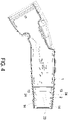
- FIG. 4 is a schematic cross-sectional view illustrating the outer casing and the strain relief structure of the charging gun of FIG. 1
- FIG. 5 is a schematic cross-sectional view illustrating the charging gun of FIG. 1
- the charging gun 100 includes an outer casing 1, a strain relief structure 2 and a cable 3.
- the cable 3 has a surface 31.
- the outer casing 1 includes a first case 11 and a second case 12, wherein the first case 11 is detachably assembled with the second case 12.
- the strain relief structure 2 includes a first portion 21, a second portion 22 and a plurality of first ring-shaped protrusions 23.
- the first portion 21 is detachably assembled with the second portion 22, the first portion 21 is disposed on a first inner wall 11a of the first case 11 (as shown in FIG. 3 ), and the second portion 22 is disposed on a second inner wall 12a of the second case 12.
- the plurality of first ring-shaped protrusions 23 disposed on the first portion 21 and the second portion 22.
- the first portion 21 When the first case 11 is assembled and connected with the second case 12, the first portion 21 is assembled and connected with the second portion 22, the first portion 21 covers on at least a part of the surface 31 of the cable 3, the second portion 22 covers on at least a part of the surface 31 of the cable 3. Consequently, the strain relief structure 2 surrounds the cable 3, and the strain relief structure 2 is clamped between the cable 3 and the outer casing 1.
- the plurality of first ring-shaped protrusions 23 are detachably attached on the surface 31 of the cable 3. When the cable 3 is bent by an external force, the strain relief structure 2 generates a supporting force in correspondence to the bending stress, so as to prevent the cable 3 from being excessively bent and broken.
- first case 11, the first portion 21, the second case 12 and the second portion 22 are respectively detachably assembled on the cable 3, it is unnecessary to apply a lubricating oil to the inner edge of the strain relief structure before assembling, and the advantages of simplifying the process of production and saving time-cost of manually assembling are achieved.
- the cable 3 of the charging gun 100 is configured for transmitting electrical power, wherein the cable 3 has a first end (not shown) and a second end (not shown).
- the first end and the second end are two opposite ends of the cable 3, wherein the first end is electrically coupled with a power supply device (not shown), wherein the power supply device is but not limited to a charging pile.
- the second end has a connector (not shown) configured to be electrically coupled with an external device (not shown), and the external device is but not limited to an electric vehicle.
- the connector is electrically coupled with the external device, the electrical power is transmitted to the external device by the power supply device through the cable 3, so that the external device is charged.
- each of the first portion 21 and the second portion 22 of the strain relief structure 2 are a curved sheet structure with semi-ring shaped cross section. When the first portion 21 and the second portion 22 are assembled with each other, the ring-shaped strain relief structure 2 is therefore formed, but not limited thereto.
- the first portion 21 of the strain relief structure 2 includes a first inner surface 21a and a first outer surface 21b.
- the first inner surface 21a and the first outer surface 21b are two opposite surfaces of the first portion 21.
- the second portion 22 of the strain relief structure 2 includes a second inner surface 22a and a second outer surface 22b.
- the second inner surface 22a and the second outer surface 22b are two opposite surfaces of the second portion 22.
- the first outer surface 21b of the first portion 21 of the strain relief structure 2 matches the first inner wall 11a of the first case 11 of the outer casing 1
- the second outer surface 22b of the second portion 22 of the strain relief structure 2 matches the second inner wall 12a of the second case 12 of the outer casing 1.
- the first case 11 and the second case 12 of the outer casing 1 are assembled by an external force, and the outer casing 1 is pressured on and tightly joined to the strain relief structure 2, so as to prevent water or liquid from flowing into the charging gun 100 via the gap between the outer casing 1 and the strain relief structure 2, and the waterproof effect is therefore enhanced.
- the first inner surface 21a of the first portion 21 of the strain relief structure 2 has a plurality of first protrusions 23a, wherein the plurality of first protrusions 23a are semi-annular convex structures protruded outwardly form the first inner surface 21a, and the plurality of first protrusions 23a are arranged adjacent to and apart from each other. As shown in FIG. 3 , the plurality of first protrusions 23a are semi-annular convex structures protruded outwardly form the first inner surface 21a, and the plurality of first protrusions 23a are arranged adjacent to and apart from each other. As shown in FIG.
- the second inner surface 22a of the second portion 22 of the strain relief structure 2 has a plurality of second protrusions 23b, wherein the plurality of second protrusions 23b are semi-annular convex structures protruded outwardly form the second inner surface 22a, and the plurality of second protrusions 23b are arranged adjacent to and apart from each other.
- the plurality of first protrusions 23a are respectively assembled and connected with the corresponding one of the second protrusions 23b, and the plurality of first ring-shaped protrusions 23 are formed thereto.
- the strain relief structure 2 covers on the cable 3
- the plurality of first ring-shaped protrusions 23 are attached on the surface 31 of the cable 3.
- the cable 3 and the strain relief structure 2 are tightly combined with each other, so as to prevent water or liquid from flowing into the charging gun 100 via the gap between the outer casing 1 and the strain relief structure 2, and the waterproof effect is therefore enhanced.
- the first outer surface 21b of the first portion 21 of the strain relief structure 2 has a plurality of first recesses 24a, wherein the plurality of first recesses 24a are semi-annular groove structures recessed inwardly from the first outer surface 21b, and the plurality of first recesses 24a are arranged adjacent to and apart from each other. As shown in FIG.
- the second outer surface 22b of the second portion 22 of the strain relief structure 2 has a plurality of second recesses 24b, wherein the plurality of second recesses 24b are semi-annular groove structures recessed inwardly from the second outer surface 22b, and the plurality of second recesses 24b are arranged adjacent to and apart from each other.
- the plurality of first recesses 24a are respectively assembled and connected with the corresponding one of the second recesses 24b, and the plurality of ring-shaped recesses 24 are formed thereto.
- the first inner wall 11a of the outer casing 1 has a plurality of third protrusions 13a, wherein the plurality of third protrusions 13a are semi-annular convex structures protruded outwardly form the first inner wall 11a, and the plurality of third protrusions 13a are arranged adjacent to and apart from each other.
- the second inner wall 12a of the outer casing 1 has a plurality of fourth protrusions 13b, wherein the plurality of fourth protrusions 13b are semi-annular convex structures protruded outwardly form the second inner wall 12a, and the plurality of fourth protrusions 13b are arranged adjacent to and apart from each other.
- the first case 11 and the second case 12 of the outer casing 12 are assembled and connected with each other
- the first portion 21 and the second portion 22 of the strain relief structure 2 are assembled and connected with each other
- the plurality of third protrusions 13a are respectively assembled and connected with the corresponding one of the fourth protrusions 13b, and a plurality of second ring-shaped protrusions 13 are formed thereto.
- the number of the plurality of second ring-shaped protrusions 13 is equal to the number of the plurality of second recesses 24, and the positions of the plurality of second ring-shaped protrusions 13 are also correspond to the plurality of second recesses 24. Therefore, the plurality of second ring-shaped protrusions 13 are detachably disposed within the corresponding one of the ring-shaped recesses 24.
- the strain relief structure 2 and the outer casing are tightly matched with each other, so as to prevent water or liquid from flowing into the charging gun 100 via the gap between the outer casing 1 and the strain relief structure 2, and the waterproof effect is therefore enhanced.
- the number and arrangement of the plurality of ring-shaped recesses 24 and the plurality of second ring-shaped protrusions 13 are not limited to the above embodiment, which can be changed according to the practical requirements.
- the strain relief structure 2 is made of a waterproof material, such as rubber, but not limited thereto.
- the strain relief structure 2 is disposed adjacent to an end 10 of the outer casing 1, and the outer casing 1 completely covers the strain relief structure 2. In other words, the strain relief structure 2 is not exposed outside the opening of the end 10 of the outer casing 1. Since the outer casing 1 completely covers the strain relief structure 2, the deformation amplitude of the strain relief structure 2 is limited, and the risk of the cable 3 being excessively bent and broken is reduced.
- the outer casing 1 of the charging gun 100 further includes a plurality of fixing components 14, wherein the plurality of fixing components 14 are configured for fixing the first case 11 and the second case 12, but not limited thereto.
- Each of the fixing components 14 includes a first fixing part 14a and a second fixing part 14b.
- the first fixing part 14a is disposed on the first case 11, the second fixing part 14b is disposed on the second case 12.
- the first fixing part 14a of the fixing component 14 is disposed on the first inner wall 11a of the first case 11, and as shown in FIG. 2 , the second fixing part 14b of the fixing component 14 is disposed on the second inner wall 12a of the second case 12.
- the first fixing part 14a and the second fixing part 14b are connected with each other in a snap-fit manner to fix the first case 11 and the second case 12, but not limited thereto.
- the first fixing part 14a and the second fixing part 14b are connected with each other in magnetic fixing or tight fitting manners, but not limited thereto.
- the outer casing 1 and the strain relief structures 2 of the charging gun 100 of the present embodiment are detachably assembled on the cable 3, the advantages of simplifying the process of production, enhancing the efficiency of production, and enhancing the effect of waterproof are achieved.
- the first portion 21 of the strain relief structures 2 is disposed within the first case 11 of the outer casing 1, wherein the first portion 21 and the first case 11 are curved sheet structures with semi-ring shaped cross section, and the first outer surface 21b of the first portion 21 is matched with the first inner wall 11a of the first case 11, so that the first portion 21 is tightly assembled with the first case 11.
- the second portion 22 of the strain relief structures 2 is disposed within the second case 12 of the outer casing 1, wherein the second portion 22 and the second case 12 are curved sheet structures with semi-ring shaped cross section, and the second outer surface 22b of the second portion 22 is also matched with the second inner wall 12a of the second case 12, so that the second portion 22 is tightly assembled with the second case 12.
- the first case 11 and the first portion 21 are correspondingly assembled and connected to the second case 12 and the second portion 22, so that the first portion 21 and the second portion 22 covers on the cable 3.
- the first case 11 and the second case 12 are combined by applying an external force, and they are fixed by the plurality of fixing components 14.
- the strain relief structure 2 is clamped between the outer casing 1 and the cable 3, the strain relief structure 2 is tightly combined with the outer casing 1 to enhance the effect of waterproof, and the strain relief structure 2 is also tightly combined with the cable 3 to enhance the effect of waterproof. Since the outer casing 1 and the strain relief structures 2 are detachably assembled on the cable 3, the advantages of simplifying the process of production, enhancing the efficiency of production, and enhancing the effect of waterproof are achieved.
- the present disclosure provides a charging gun. Since the first case of the outer casing, the first portion of the strain relief structure, the second case of the outer casing and the second portion of the strain relief structure are detachably assembled on the cable, it is unnecessary to apply a lubricating oil to the inner edge of the strain relief structure before assembling, and the advantages of simplifying the process of production and saving time-cost of manually assembling are achieved.
- the strain relief structure matches the outer casing, and the outer casing pressures on and tightly joined to the strain relief structure, so as to prevent water or liquid from flowing into the charging gun via the gap between the outer casing and the strain relief structure, and the waterproof effect is therefore enhanced.
- the arrangement of the plurality of first ring-shaped protrusions is benefit in that the cable and the strain relief structure can be tightly combined with each other, so as to prevent water or liquid from flowing into the charging gun via the gap between the outer casing and the strain relief structure, and the waterproof effect is therefore enhanced.
Landscapes
- Engineering & Computer Science (AREA)
- Power Engineering (AREA)
- Transportation (AREA)
- Mechanical Engineering (AREA)
- Details Of Connecting Devices For Male And Female Coupling (AREA)
- Electric Propulsion And Braking For Vehicles (AREA)
- Installation Of Indoor Wiring (AREA)
- Charge And Discharge Circuits For Batteries Or The Like (AREA)
Abstract
Description
- The present disclosure relates to a charging equipment, and more particularly to a charging gun having a strain relief structure.
- Generally speaking, the charging equipment includes a charging gun and a power supply device, the charging gun is in connection with the power supply device, so that an external device can be charged by the power supply device through the charging gun. A cable of the charging gun (e.g. power cable) is usually bent while using, and the cable near the connection terminal may be broken due to excessive stress.
- At present, there are many charging guns having a strain relief structure near the connection terminal of the cable. The traditional strain relief structure is an integrally-formed ring-shaped structure and arranged around the cable. However, the above-mentioned cables are usually inserted into the strain relief structure by manual assembly, and a lubricating oil must be applied to the inner edge of the strain relief structure before assembling for reducing the friction, which results in time-consuming and inconvenient assembly, low producing efficiency and poor waterproof effect.
- Therefore, there is a need of providing an improved charging gun and the strain relief structure thereof to obviate the drawbacks of the prior art.
- It is an object of the present disclosure to provide a charging gun having a strain relief structure, which achieves the advantages of simplifying the process of production, saving time-cost of manually assembling, enhancing the efficiency and stability of production, and enhancing the effect of waterproof.
- It is an object of the present disclosure to provide a charging gun. The charging gun includes a cable, an outer casing and a strain relief structure. The cable has a surface. The outer casing includes a first case and a second case, wherein the first case is detachably assembled with the second case. The strain relief structure includes a first portion and a second portion, wherein the first portion is detachably assembled with the second portion, the first portion is disposed on a first inner wall of the first case, and the second portion is disposed on a second inner wall of the second case. When the first case is assembled and connected with the second case, the first portion is assembled and connected with the second portion, the first portion covers on at least a part of the surface of the cable, the second portion covers on at least a part of the surface of the cable, and the strain relief structure is clamped between the cable and the outer casing.
- It is another object of the present disclosure to provide a strain relief structure for a charging gun. The charging gun includes a cable and an outer casing. The outer casing includes a first case and a second case, the first case is detachably assembled with the second case. The strain relief structure includes a first portion, a second portion and a plurality of first ring-shaped protrusions. The second portion detachably assembled with the first portion. The plurality of first ring-shaped protrusions disposed on the first portion and the second portion. The first portion is assembled and connected with the second portion, the first portion covers on at least a part of a surface of the cable, the second portion covers on at least a part of the surface of the cable, and the plurality of first ring-shaped protrusions are detachably attached on the surface of the cable.
- The above contents of the present invention will become more readily apparent to those ordinarily skilled in the art after reviewing the following detailed description and accompanying drawings, in which:
-
-
FIG. 1 is a schematic perspective view illustrating a charging gun according to an embodiment of the present disclosure; -
FIG. 2 is a schematic exploded view illustrating an outer casing and a strain relief structure of the charging gun ofFIG. 1 ; -
FIG. 3 is another schematic perspective view illustrating the charging gun ofFIG. 1 ; -
FIG. 4 is a schematic cross-sectional view illustrating the outer casing and the strain relief structure of the charging gun ofFIG. 1 ; and -
FIG. 5 is a schematic cross-sectional view illustrating the charging gun ofFIG. 1 . - The present invention will now be described more specifically with reference to the following embodiments. It is to be noted that the following descriptions of preferred embodiments of this invention are presented herein for purpose of illustration and description only. It is not intended to be exhaustive or to be limited to the precise form disclosed.
- Please refer to
FIGS.1 to 5 , whereinFIG. 1 is a schematic perspective view illustrating a charging gun according to an embodiment of the present disclosure;FIG. 2 is a schematic exploded view illustrating an outer casing and a strain relief structure of the charging gun ofFIG. 1 ;FIG. 3 is another schematic perspective view illustrating the charging gun ofFIG. 1 ;FIG. 4 is a schematic cross-sectional view illustrating the outer casing and the strain relief structure of the charging gun ofFIG. 1 ; andFIG. 5 is a schematic cross-sectional view illustrating the charging gun ofFIG. 1 . In the present embodiment, thecharging gun 100 includes anouter casing 1, astrain relief structure 2 and acable 3. Thecable 3 has asurface 31. Theouter casing 1 includes afirst case 11 and asecond case 12, wherein thefirst case 11 is detachably assembled with thesecond case 12. Thestrain relief structure 2 includes afirst portion 21, asecond portion 22 and a plurality of first ring-shaped protrusions 23. Thefirst portion 21 is detachably assembled with thesecond portion 22, thefirst portion 21 is disposed on a firstinner wall 11a of the first case 11 (as shown inFIG. 3 ), and thesecond portion 22 is disposed on a secondinner wall 12a of thesecond case 12. The plurality of first ring-shaped protrusions 23 disposed on thefirst portion 21 and thesecond portion 22. When thefirst case 11 is assembled and connected with thesecond case 12, thefirst portion 21 is assembled and connected with thesecond portion 22, thefirst portion 21 covers on at least a part of thesurface 31 of thecable 3, thesecond portion 22 covers on at least a part of thesurface 31 of thecable 3. Consequently, thestrain relief structure 2 surrounds thecable 3, and thestrain relief structure 2 is clamped between thecable 3 and theouter casing 1. The plurality of first ring-shaped protrusions 23 are detachably attached on thesurface 31 of thecable 3. When thecable 3 is bent by an external force, thestrain relief structure 2 generates a supporting force in correspondence to the bending stress, so as to prevent thecable 3 from being excessively bent and broken. Moreover, since thefirst case 11, thefirst portion 21, thesecond case 12 and thesecond portion 22 are respectively detachably assembled on thecable 3, it is unnecessary to apply a lubricating oil to the inner edge of the strain relief structure before assembling, and the advantages of simplifying the process of production and saving time-cost of manually assembling are achieved. - In an embodiment, the
cable 3 of thecharging gun 100 is configured for transmitting electrical power, wherein thecable 3 has a first end (not shown) and a second end (not shown). The first end and the second end are two opposite ends of thecable 3, wherein the first end is electrically coupled with a power supply device (not shown), wherein the power supply device is but not limited to a charging pile. The second end has a connector (not shown) configured to be electrically coupled with an external device (not shown), and the external device is but not limited to an electric vehicle. When the connector is electrically coupled with the external device, the electrical power is transmitted to the external device by the power supply device through thecable 3, so that the external device is charged. - Please refer to
FIGS. 2 and3 . In the present embodiment, each of thefirst portion 21 and thesecond portion 22 of thestrain relief structure 2 are a curved sheet structure with semi-ring shaped cross section. When thefirst portion 21 and thesecond portion 22 are assembled with each other, the ring-shapedstrain relief structure 2 is therefore formed, but not limited thereto. In the present embodiment, thefirst portion 21 of thestrain relief structure 2 includes a firstinner surface 21a and a firstouter surface 21b. The firstinner surface 21a and the firstouter surface 21b are two opposite surfaces of thefirst portion 21. Thesecond portion 22 of thestrain relief structure 2 includes a secondinner surface 22a and a secondouter surface 22b. The secondinner surface 22a and the secondouter surface 22b are two opposite surfaces of thesecond portion 22. The firstouter surface 21b of thefirst portion 21 of thestrain relief structure 2 matches the firstinner wall 11a of thefirst case 11 of theouter casing 1, and the secondouter surface 22b of thesecond portion 22 of thestrain relief structure 2 matches the secondinner wall 12a of thesecond case 12 of theouter casing 1. Thefirst case 11 and thesecond case 12 of theouter casing 1 are assembled by an external force, and theouter casing 1 is pressured on and tightly joined to thestrain relief structure 2, so as to prevent water or liquid from flowing into thecharging gun 100 via the gap between theouter casing 1 and thestrain relief structure 2, and the waterproof effect is therefore enhanced. - Please refer to
FIGS. 2 to 4 . In the present embodiment, as shown inFIG. 3 , the firstinner surface 21a of thefirst portion 21 of thestrain relief structure 2 has a plurality offirst protrusions 23a, wherein the plurality offirst protrusions 23a are semi-annular convex structures protruded outwardly form the firstinner surface 21a, and the plurality offirst protrusions 23a are arranged adjacent to and apart from each other. As shown inFIG. 2 , the secondinner surface 22a of thesecond portion 22 of thestrain relief structure 2 has a plurality ofsecond protrusions 23b, wherein the plurality ofsecond protrusions 23b are semi-annular convex structures protruded outwardly form the secondinner surface 22a, and the plurality ofsecond protrusions 23b are arranged adjacent to and apart from each other. When thefirst portion 21 and thesecond portion 22 of thestrain relief structure 2 are assembled and connected with each other, the plurality offirst protrusions 23a are respectively assembled and connected with the corresponding one of thesecond protrusions 23b, and the plurality of first ring-shaped protrusions 23 are formed thereto. When thestrain relief structure 2 covers on thecable 3, the plurality of first ring-shaped protrusions 23 are attached on thesurface 31 of thecable 3. By the arrangement of the plurality of first ring-shapedprotrusions 23, thecable 3 and thestrain relief structure 2 are tightly combined with each other, so as to prevent water or liquid from flowing into the charginggun 100 via the gap between theouter casing 1 and thestrain relief structure 2, and the waterproof effect is therefore enhanced. - Please refer to
FIGS. 2 to 4 . In the present embodiment, the firstouter surface 21b of thefirst portion 21 of thestrain relief structure 2 has a plurality offirst recesses 24a, wherein the plurality offirst recesses 24a are semi-annular groove structures recessed inwardly from the firstouter surface 21b, and the plurality offirst recesses 24a are arranged adjacent to and apart from each other. As shown inFIG. 3 , the secondouter surface 22b of thesecond portion 22 of thestrain relief structure 2 has a plurality ofsecond recesses 24b, wherein the plurality ofsecond recesses 24b are semi-annular groove structures recessed inwardly from the secondouter surface 22b, and the plurality ofsecond recesses 24b are arranged adjacent to and apart from each other. When thefirst portion 21 is assembled and connected with thesecond portion 22, the plurality offirst recesses 24a are respectively assembled and connected with the corresponding one of thesecond recesses 24b, and the plurality of ring-shapedrecesses 24 are formed thereto. - Please refer to
FIGS. 2 to 4 . In the present embodiment, as shown inFIG. 3 , the firstinner wall 11a of theouter casing 1 has a plurality ofthird protrusions 13a, wherein the plurality ofthird protrusions 13a are semi-annular convex structures protruded outwardly form the firstinner wall 11a, and the plurality ofthird protrusions 13a are arranged adjacent to and apart from each other. The secondinner wall 12a of theouter casing 1 has a plurality offourth protrusions 13b, wherein the plurality offourth protrusions 13b are semi-annular convex structures protruded outwardly form the secondinner wall 12a, and the plurality offourth protrusions 13b are arranged adjacent to and apart from each other. When thefirst case 11 and thesecond case 12 of theouter casing 12 are assembled and connected with each other, thefirst portion 21 and thesecond portion 22 of thestrain relief structure 2 are assembled and connected with each other, and the plurality ofthird protrusions 13a are respectively assembled and connected with the corresponding one of thefourth protrusions 13b, and a plurality of second ring-shapedprotrusions 13 are formed thereto. - Please refer to
FIGS. 2 to 4 . In the present embodiment, the number of the plurality of second ring-shapedprotrusions 13 is equal to the number of the plurality ofsecond recesses 24, and the positions of the plurality of second ring-shapedprotrusions 13 are also correspond to the plurality ofsecond recesses 24. Therefore, the plurality of second ring-shapedprotrusions 13 are detachably disposed within the corresponding one of the ring-shapedrecesses 24. Since the plurality of second ring-shapedprotrusions 13 are disposed within the corresponding one of the ring-shapedrecesses 24, thestrain relief structure 2 and the outer casing are tightly matched with each other, so as to prevent water or liquid from flowing into the charginggun 100 via the gap between theouter casing 1 and thestrain relief structure 2, and the waterproof effect is therefore enhanced. The number and arrangement of the plurality of ring-shapedrecesses 24 and the plurality of second ring-shapedprotrusions 13 are not limited to the above embodiment, which can be changed according to the practical requirements. In the present embodiment, thestrain relief structure 2 is made of a waterproof material, such as rubber, but not limited thereto. - Please refer to
FIGS. 1 ,4 and5 . In the present embodiment, thestrain relief structure 2 is disposed adjacent to an end 10 of theouter casing 1, and theouter casing 1 completely covers thestrain relief structure 2. In other words, thestrain relief structure 2 is not exposed outside the opening of the end 10 of theouter casing 1. Since theouter casing 1 completely covers thestrain relief structure 2, the deformation amplitude of thestrain relief structure 2 is limited, and the risk of thecable 3 being excessively bent and broken is reduced. - Please refer to
FIGS. 2 and3 . In the present embodiment, theouter casing 1 of the charginggun 100 further includes a plurality of fixingcomponents 14, wherein the plurality of fixingcomponents 14 are configured for fixing thefirst case 11 and thesecond case 12, but not limited thereto. Each of the fixingcomponents 14 includes afirst fixing part 14a and asecond fixing part 14b. Thefirst fixing part 14a is disposed on thefirst case 11, thesecond fixing part 14b is disposed on thesecond case 12. When thefirst case 11 is assembled and connected with thesecond case 12, the first fixingpart 14a and thesecond fixing part 14b are connected with each other, and thefirst case 11 is fixed to thesecond case 12, so as to prevent thefirst case 11 and thesecond case 12 from being bounced off by the pressure applied to thestrain relief structure 2. In the present embodiment, as shown inFIG. 3 , the first fixingpart 14a of the fixingcomponent 14 is disposed on the firstinner wall 11a of thefirst case 11, and as shown inFIG. 2 , thesecond fixing part 14b of the fixingcomponent 14 is disposed on the secondinner wall 12a of thesecond case 12. Thefirst fixing part 14a and thesecond fixing part 14b are connected with each other in a snap-fit manner to fix thefirst case 11 and thesecond case 12, but not limited thereto. In some embodiments, the first fixingpart 14a and thesecond fixing part 14b are connected with each other in magnetic fixing or tight fitting manners, but not limited thereto. - Please refer to
FIGS. 1 to 5 . Since theouter casing 1 and thestrain relief structures 2 of the charginggun 100 of the present embodiment are detachably assembled on thecable 3, the advantages of simplifying the process of production, enhancing the efficiency of production, and enhancing the effect of waterproof are achieved. First of all, thefirst portion 21 of thestrain relief structures 2 is disposed within thefirst case 11 of theouter casing 1, wherein thefirst portion 21 and thefirst case 11 are curved sheet structures with semi-ring shaped cross section, and the firstouter surface 21b of thefirst portion 21 is matched with the firstinner wall 11a of thefirst case 11, so that thefirst portion 21 is tightly assembled with thefirst case 11. Thesecond portion 22 of thestrain relief structures 2 is disposed within thesecond case 12 of theouter casing 1, wherein thesecond portion 22 and thesecond case 12 are curved sheet structures with semi-ring shaped cross section, and the secondouter surface 22b of thesecond portion 22 is also matched with the secondinner wall 12a of thesecond case 12, so that thesecond portion 22 is tightly assembled with thesecond case 12. Next, thefirst case 11 and thefirst portion 21 are correspondingly assembled and connected to thesecond case 12 and thesecond portion 22, so that thefirst portion 21 and thesecond portion 22 covers on thecable 3. Finally, thefirst case 11 and thesecond case 12 are combined by applying an external force, and they are fixed by the plurality of fixingcomponents 14. Therefore, thestrain relief structure 2 is clamped between theouter casing 1 and thecable 3, thestrain relief structure 2 is tightly combined with theouter casing 1 to enhance the effect of waterproof, and thestrain relief structure 2 is also tightly combined with thecable 3 to enhance the effect of waterproof. Since theouter casing 1 and thestrain relief structures 2 are detachably assembled on thecable 3, the advantages of simplifying the process of production, enhancing the efficiency of production, and enhancing the effect of waterproof are achieved. - In summary, the present disclosure provides a charging gun. Since the first case of the outer casing, the first portion of the strain relief structure, the second case of the outer casing and the second portion of the strain relief structure are detachably assembled on the cable, it is unnecessary to apply a lubricating oil to the inner edge of the strain relief structure before assembling, and the advantages of simplifying the process of production and saving time-cost of manually assembling are achieved. In addition, the strain relief structure matches the outer casing, and the outer casing pressures on and tightly joined to the strain relief structure, so as to prevent water or liquid from flowing into the charging gun via the gap between the outer casing and the strain relief structure, and the waterproof effect is therefore enhanced. Consequently, the arrangement of the plurality of first ring-shaped protrusions is benefit in that the cable and the strain relief structure can be tightly combined with each other, so as to prevent water or liquid from flowing into the charging gun via the gap between the outer casing and the strain relief structure, and the waterproof effect is therefore enhanced.
Claims (13)
- A charging gun (100), characterized by comprising:a cable (3) having a surface (31);an outer casing (1) comprising a first case (11) and a second case (12), wherein the first case (11) is detachably assembled with the second case (12); anda strain relief structure (2) comprising a first portion (21) and a second portion (22), wherein the first portion (21) is detachably assembled with the second portion (22), the first portion (21) is disposed on a first inner wall (11a) of the first case (11), and the second portion (22) is disposed on a second inner wall (12a) of the second case (12);wherein when the first case (11) is assembled and connected with the second case (12), the first portion (21) is assembled and connected with the second portion (22), the first portion (21) covers on at least a part of the surface (31) of the cable (3), the second portion (22) covers on at least a part of the surface (31) of the cable (3), and the strain relief structure (2) is clamped between the cable (3) and the outer casing (1).
- The charging gun (100) according to claim 1, wherein a first outer surface (21b) of the first portion (21) matches the first inner wall (11a) of the first case (11), and a second outer surface (22b) of the second portion (22) matches the second inner wall (12a) of the second case (12).
- The charging gun (100) according to claim 2, wherein the first outer surface (21b) of the first portion (21) of the strain relief structure (2) has a plurality of first recesses (24a), a second outer surface (22b) of the second portion (22) of the strain relief structure (2) has a plurality of second recesses (24b), wherein when the first portion (21) is assembled and connected with the second portion (22), the plurality of first recesses (24a) are respectively assembled with the corresponding one of the second recesses (24b), and a plurality of ring-shaped recesses (24) are formed thereto.
- The charging gun (100) according to claim 3, wherein the first inner wall (11a) of the outer casing (1) has a plurality of third protrusions (13a), the second inner wall (12a) has a plurality of fourth protrusions (13b), when the first portion (21) and the second portion (22) of the strain relief structure (2) are assembled with each other, the plurality of third protrusions (13a) are respectively assembled with the corresponding one of the fourth protrusions (13b), and a plurality of second ring-shaped protrusions (13) are formed thereto, wherein the plurality of second ring-shaped protrusions (13) are detachably disposed within the corresponding one of the ring-shaped recesses (24).
- The charging gun (100) according to claim 1, wherein a first inner surface (21a) of the first portion (21) of the strain relief structure (2) has a plurality of first protrusions (23a), a second inner surface (22a) of the second portion (22) has a plurality of second protrusions (23b), when the first portion (21) and the second portion (22) are assembled with each other, the plurality of first protrusions (23a) are respectively assembled with the corresponding one of the second protrusions (23b), and a plurality of first ring-shaped protrusions (23) are formed thereto, wherein the plurality of first ring-shaped protrusions (23) are detachably attached with the surface (31) of the cable (3).
- The charging gun (100) according to claim 1, wherein the outer casing (1) completely covers the strain relief structure (2).
- The charging gun (100) according to claim 1, wherein the strain relief structure (2) is disposed adjacent to an end (10) of the outer casing (1).
- The charging gun (100) according to claim 1, wherein the outer casing (1) further comprises at least one fixing component (14), the at least one fixing component (14) comprises a first fixing part (14a) and a second fixing part (14b), the first fixing part (14a) is disposed on the first case (11), the second fixing part (14b) is disposed on the second case (12), wherein when the first case (11) is assembled and connected with the second case (12), the first fixing part (14a) and the second fixing part (14b) are connected with each other, and the first case (11) is fixed to the second case (12).
- A strain relief structure (2) for a charging gun (100), wherein the charging gun (100) comprises a cable (3) and an outer casing (1), the outer casing (1) comprises a first case (11) and a second case (12), and the first case (11) is detachably assembled with the second case (12), characterized in that the strain relief structure (2) comprises:a first portion (21);a second portion (22) detachably assembled with the first portion (21); anda plurality of first ring-shaped protrusions (23) disposed on the first portion (21) and the second portion (22);wherein the first portion (21) is assembled and connected with the second portion (22), the first portion (21) covers on at least a part of a surface (31) of the cable (3), the second portion (22) covers on at least a part of the surface (31) of the cable (3), and the plurality of first ring-shaped protrusions (23) are detachably attached on the surface (31) of the cable (3).
- The strain relief structure (2) according to claim 9, wherein a first outer surface (21b) of the first portion (21) matches the first inner wall (11a) of the first case (11), and a second outer surface (22b) of the second portion (22) matches the second inner wall (12a) of the second case (12).
- The strain relief structure (2) according to claim 10, wherein the first outer surface (21b) of the first portion (21) has a plurality of first recesses (24a), a second outer surface (22b) of the second portion (22) of the strain relief structure (2) has a plurality of second recesses (24b), wherein when the first portion (21) is assembled and connected with the second portion (22), the plurality of first recesses (24a) are respectively assembled with the corresponding one of the second recesses (24b), and a plurality of ring-shaped recesses (24) are formed thereto, wherein the plurality of ring-shaped recesses (24) are configured for respectively accommodating corresponding one of second protrusions (23b) of the outer casing (1).
- The strain relief structure (2) according to claim 9, wherein a first inner surface (21a) of the first portion (21) of the strain relief structure (2) has a plurality of first protrusions (23a), a second inner surface (22a) of the second portion (22) has a plurality of second protrusions (23b), wherein when the first portion (21) and the second portion (22) are assembled with each other, the plurality of first protrusions (23a) are respectively assembled with the corresponding one of the second protrusions (23b), and the plurality of first ring-shaped protrusions (23) are formed thereto.
- The strain relief structure (2) according to claim 9, the strain relief structure (2) is made of a waterproof material.
Applications Claiming Priority (1)
| Application Number | Priority Date | Filing Date | Title |
|---|---|---|---|
| CN202011205427.7A CN114447676A (en) | 2020-11-02 | 2020-11-02 | Charging gun and stress relieving structure thereof |
Publications (3)
| Publication Number | Publication Date |
|---|---|
| EP3993179A1 true EP3993179A1 (en) | 2022-05-04 |
| EP3993179B1 EP3993179B1 (en) | 2024-08-14 |
| EP3993179C0 EP3993179C0 (en) | 2024-08-14 |
Family
ID=76623963
Family Applications (1)
| Application Number | Title | Priority Date | Filing Date |
|---|---|---|---|
| EP21181770.5A Active EP3993179B1 (en) | 2020-11-02 | 2021-06-25 | Charging gun and strain relief structure thereof |
Country Status (3)
| Country | Link |
|---|---|
| US (1) | US11646529B2 (en) |
| EP (1) | EP3993179B1 (en) |
| CN (1) | CN114447676A (en) |
Families Citing this family (7)
| Publication number | Priority date | Publication date | Assignee | Title |
|---|---|---|---|---|
| CN114552277A (en) * | 2020-11-24 | 2022-05-27 | 台达电子工业股份有限公司 | Charging gun |
| CN115131914B (en) * | 2022-06-29 | 2023-12-05 | 东风汽车有限公司东风日产乘用车公司 | Charging port cover control method, device, equipment and storage medium |
| USD1044736S1 (en) * | 2023-07-21 | 2024-10-01 | Weihuang Mai | Charging gun |
| USD1079618S1 (en) * | 2023-07-28 | 2025-06-17 | Guangdong Chongwei technology Co., LTD | Charging gun |
| USD1098006S1 (en) * | 2023-11-07 | 2025-10-14 | Juntao Hu | Electric vehicle charger plug |
| USD1123875S1 (en) | 2024-11-05 | 2026-04-28 | Delta Electronics, Inc. | Cable sheath |
| CN122026257A (en) * | 2024-11-05 | 2026-05-12 | 台达电子工业股份有限公司 | Cable sheath and its charging gun |
Citations (3)
| Publication number | Priority date | Publication date | Assignee | Title |
|---|---|---|---|---|
| US20130052853A1 (en) * | 2011-08-22 | 2013-02-28 | Lear Corporation | Connector assembly |
| US20150147919A1 (en) * | 2013-11-28 | 2015-05-28 | Phoenix Contact Gmbh & Co. Kg | Charging cable connector |
| US20160315414A1 (en) * | 2015-04-27 | 2016-10-27 | Tyco Electronics Corporation | Connector housing assembly for sealing to a cable |
Family Cites Families (12)
| Publication number | Priority date | Publication date | Assignee | Title |
|---|---|---|---|---|
| WO2007112771A1 (en) * | 2006-04-04 | 2007-10-11 | Fci | Retention ferrule for cable connector |
| CN101098061A (en) | 2006-06-27 | 2008-01-02 | 富士康(昆山)电脑接插件有限公司 | Cable Connector Assembly |
| US20150144394A1 (en) | 2012-05-14 | 2015-05-28 | Next Wave Design Pty Ltd | Cable holder |
| EP2816672B1 (en) * | 2013-06-21 | 2016-11-16 | Delphi Technologies, Inc. | Strain relief system for an electrical connector assembly |
| DE102014008343A1 (en) | 2014-06-04 | 2015-12-17 | Kostal Kontakt Systeme Gmbh | Electric device |
| CN105490241B (en) * | 2016-01-12 | 2017-11-14 | 浙江亿电电气有限公司 | Pipe jacket-type plugging device |
| CN205791392U (en) * | 2016-05-27 | 2016-12-07 | 国家电网公司 | Transmission line of electricity protects wire type suspension clamp |
| TWM536429U (en) | 2016-10-25 | 2017-02-01 | Aces Electronics Co Ltd | Improved structure of charging gun |
| WO2019023094A1 (en) | 2017-07-24 | 2019-01-31 | Molex, Llc | Cable connector |
| US10290970B1 (en) | 2018-02-08 | 2019-05-14 | Delphi Technologies, Llc | Connector with strain relief device |
| CN110654257A (en) | 2018-06-28 | 2020-01-07 | 深圳市白狐工业设计有限公司 | Waterproof construction and rifle that charges |
| CN208489423U (en) * | 2018-06-29 | 2019-02-12 | 深圳灵科技术有限公司 | A kind of charging gun shell structure |
-
2020
- 2020-11-02 CN CN202011205427.7A patent/CN114447676A/en active Pending
-
2021
- 2021-06-14 US US17/347,146 patent/US11646529B2/en active Active
- 2021-06-25 EP EP21181770.5A patent/EP3993179B1/en active Active
Patent Citations (3)
| Publication number | Priority date | Publication date | Assignee | Title |
|---|---|---|---|---|
| US20130052853A1 (en) * | 2011-08-22 | 2013-02-28 | Lear Corporation | Connector assembly |
| US20150147919A1 (en) * | 2013-11-28 | 2015-05-28 | Phoenix Contact Gmbh & Co. Kg | Charging cable connector |
| US20160315414A1 (en) * | 2015-04-27 | 2016-10-27 | Tyco Electronics Corporation | Connector housing assembly for sealing to a cable |
Also Published As
| Publication number | Publication date |
|---|---|
| US11646529B2 (en) | 2023-05-09 |
| EP3993179B1 (en) | 2024-08-14 |
| EP3993179C0 (en) | 2024-08-14 |
| US20220140526A1 (en) | 2022-05-05 |
| CN114447676A (en) | 2022-05-06 |
Similar Documents
| Publication | Publication Date | Title |
|---|---|---|
| US11646529B2 (en) | Charging gun and strain relief structure thereof | |
| EP2360050A2 (en) | Power supply control device | |
| CN102522662B (en) | Electrical connector providing electrical power to an antenna | |
| US10734750B2 (en) | Closing-body holding structure and electric wire with connector | |
| US20190229460A1 (en) | Protective cover element and waterproof housing for electrically functional components | |
| US10446976B2 (en) | Shield connector and connector connection structure | |
| CN207426217U (en) | Adaptor connector | |
| CN110190451A (en) | Connector and its shielding sleeve assembly | |
| US12431668B2 (en) | Shield connector | |
| CN109524193B (en) | Explosion-proof electromagnet device | |
| CN218975950U (en) | A shielding structure and connector | |
| CN111404096A (en) | Cable connector and electrical equipment with same | |
| TWI771789B (en) | Charging gun and strain relief structure thereof | |
| CN215989402U (en) | Sealing device for cable connector and corresponding wire harness product | |
| CN110571576A (en) | A connector and ferrule assembly thereof | |
| KR102503752B1 (en) | Micro usb plug connector | |
| CN215119371U (en) | waterproof box | |
| CN222995970U (en) | A cable wall sealing shielding structure and cable connector | |
| CN220272788U (en) | Right-angle socket | |
| CN223261002U (en) | Electric connector | |
| CN223109322U (en) | A double-ended wiring connector | |
| EP3654459A1 (en) | Battery product and assembling method thereof | |
| CN219041365U (en) | Cable metal sheath fracture sealing device | |
| CN220021700U (en) | Plug structure and electric equipment | |
| CN222705924U (en) | Electric wire harness connector |
Legal Events
| Date | Code | Title | Description |
|---|---|---|---|
| PUAI | Public reference made under article 153(3) epc to a published international application that has entered the european phase |
Free format text: ORIGINAL CODE: 0009012 |
|
| STAA | Information on the status of an ep patent application or granted ep patent |
Free format text: STATUS: THE APPLICATION HAS BEEN PUBLISHED |
|
| AK | Designated contracting states |
Kind code of ref document: A1 Designated state(s): AL AT BE BG CH CY CZ DE DK EE ES FI FR GB GR HR HU IE IS IT LI LT LU LV MC MK MT NL NO PL PT RO RS SE SI SK SM TR |
|
| STAA | Information on the status of an ep patent application or granted ep patent |
Free format text: STATUS: REQUEST FOR EXAMINATION WAS MADE |
|
| 17P | Request for examination filed |
Effective date: 20221024 |
|
| RBV | Designated contracting states (corrected) |
Designated state(s): AL AT BE BG CH CY CZ DE DK EE ES FI FR GB GR HR HU IE IS IT LI LT LU LV MC MK MT NL NO PL PT RO RS SE SI SK SM TR |
|
| GRAP | Despatch of communication of intention to grant a patent |
Free format text: ORIGINAL CODE: EPIDOSNIGR1 |
|
| STAA | Information on the status of an ep patent application or granted ep patent |
Free format text: STATUS: GRANT OF PATENT IS INTENDED |
|
| INTG | Intention to grant announced |
Effective date: 20240318 |
|
| GRAS | Grant fee paid |
Free format text: ORIGINAL CODE: EPIDOSNIGR3 |
|
| GRAA | (expected) grant |
Free format text: ORIGINAL CODE: 0009210 |
|
| STAA | Information on the status of an ep patent application or granted ep patent |
Free format text: STATUS: THE PATENT HAS BEEN GRANTED |
|
| AK | Designated contracting states |
Kind code of ref document: B1 Designated state(s): AL AT BE BG CH CY CZ DE DK EE ES FI FR GB GR HR HU IE IS IT LI LT LU LV MC MK MT NL NO PL PT RO RS SE SI SK SM TR |
|
| REG | Reference to a national code |
Ref country code: GB Ref legal event code: FG4D |
|
| REG | Reference to a national code |
Ref country code: CH Ref legal event code: EP |
|
| REG | Reference to a national code |
Ref country code: DE Ref legal event code: R096 Ref document number: 602021017091 Country of ref document: DE |
|
| REG | Reference to a national code |
Ref country code: IE Ref legal event code: FG4D |
|
| U01 | Request for unitary effect filed |
Effective date: 20240912 |
|
| U07 | Unitary effect registered |
Designated state(s): AT BE BG DE DK EE FI FR IT LT LU LV MT NL PT RO SE SI Effective date: 20240930 |
|
| PG25 | Lapsed in a contracting state [announced via postgrant information from national office to epo] |
Ref country code: NO Free format text: LAPSE BECAUSE OF FAILURE TO SUBMIT A TRANSLATION OF THE DESCRIPTION OR TO PAY THE FEE WITHIN THE PRESCRIBED TIME-LIMIT Effective date: 20241114 |
|
| PG25 | Lapsed in a contracting state [announced via postgrant information from national office to epo] |
Ref country code: GR Free format text: LAPSE BECAUSE OF FAILURE TO SUBMIT A TRANSLATION OF THE DESCRIPTION OR TO PAY THE FEE WITHIN THE PRESCRIBED TIME-LIMIT Effective date: 20241115 Ref country code: PL Free format text: LAPSE BECAUSE OF FAILURE TO SUBMIT A TRANSLATION OF THE DESCRIPTION OR TO PAY THE FEE WITHIN THE PRESCRIBED TIME-LIMIT Effective date: 20240814 |
|
| PG25 | Lapsed in a contracting state [announced via postgrant information from national office to epo] |
Ref country code: IS Free format text: LAPSE BECAUSE OF FAILURE TO SUBMIT A TRANSLATION OF THE DESCRIPTION OR TO PAY THE FEE WITHIN THE PRESCRIBED TIME-LIMIT Effective date: 20241214 |
|
| PG25 | Lapsed in a contracting state [announced via postgrant information from national office to epo] |
Ref country code: HR Free format text: LAPSE BECAUSE OF FAILURE TO SUBMIT A TRANSLATION OF THE DESCRIPTION OR TO PAY THE FEE WITHIN THE PRESCRIBED TIME-LIMIT Effective date: 20240814 |
|
| PG25 | Lapsed in a contracting state [announced via postgrant information from national office to epo] |
Ref country code: RS Free format text: LAPSE BECAUSE OF FAILURE TO SUBMIT A TRANSLATION OF THE DESCRIPTION OR TO PAY THE FEE WITHIN THE PRESCRIBED TIME-LIMIT Effective date: 20241114 Ref country code: ES Free format text: LAPSE BECAUSE OF FAILURE TO SUBMIT A TRANSLATION OF THE DESCRIPTION OR TO PAY THE FEE WITHIN THE PRESCRIBED TIME-LIMIT Effective date: 20240814 |
|
| PG25 | Lapsed in a contracting state [announced via postgrant information from national office to epo] |
Ref country code: RS Free format text: LAPSE BECAUSE OF FAILURE TO SUBMIT A TRANSLATION OF THE DESCRIPTION OR TO PAY THE FEE WITHIN THE PRESCRIBED TIME-LIMIT Effective date: 20241114 Ref country code: PL Free format text: LAPSE BECAUSE OF FAILURE TO SUBMIT A TRANSLATION OF THE DESCRIPTION OR TO PAY THE FEE WITHIN THE PRESCRIBED TIME-LIMIT Effective date: 20240814 Ref country code: NO Free format text: LAPSE BECAUSE OF FAILURE TO SUBMIT A TRANSLATION OF THE DESCRIPTION OR TO PAY THE FEE WITHIN THE PRESCRIBED TIME-LIMIT Effective date: 20241114 Ref country code: IS Free format text: LAPSE BECAUSE OF FAILURE TO SUBMIT A TRANSLATION OF THE DESCRIPTION OR TO PAY THE FEE WITHIN THE PRESCRIBED TIME-LIMIT Effective date: 20241214 Ref country code: HR Free format text: LAPSE BECAUSE OF FAILURE TO SUBMIT A TRANSLATION OF THE DESCRIPTION OR TO PAY THE FEE WITHIN THE PRESCRIBED TIME-LIMIT Effective date: 20240814 Ref country code: GR Free format text: LAPSE BECAUSE OF FAILURE TO SUBMIT A TRANSLATION OF THE DESCRIPTION OR TO PAY THE FEE WITHIN THE PRESCRIBED TIME-LIMIT Effective date: 20241115 Ref country code: ES Free format text: LAPSE BECAUSE OF FAILURE TO SUBMIT A TRANSLATION OF THE DESCRIPTION OR TO PAY THE FEE WITHIN THE PRESCRIBED TIME-LIMIT Effective date: 20240814 |
|
| PG25 | Lapsed in a contracting state [announced via postgrant information from national office to epo] |
Ref country code: SM Free format text: LAPSE BECAUSE OF FAILURE TO SUBMIT A TRANSLATION OF THE DESCRIPTION OR TO PAY THE FEE WITHIN THE PRESCRIBED TIME-LIMIT Effective date: 20240814 |
|
| PG25 | Lapsed in a contracting state [announced via postgrant information from national office to epo] |
Ref country code: CZ Free format text: LAPSE BECAUSE OF FAILURE TO SUBMIT A TRANSLATION OF THE DESCRIPTION OR TO PAY THE FEE WITHIN THE PRESCRIBED TIME-LIMIT Effective date: 20240814 |
|
| PG25 | Lapsed in a contracting state [announced via postgrant information from national office to epo] |
Ref country code: SK Free format text: LAPSE BECAUSE OF FAILURE TO SUBMIT A TRANSLATION OF THE DESCRIPTION OR TO PAY THE FEE WITHIN THE PRESCRIBED TIME-LIMIT Effective date: 20240814 |
|
| U20 | Renewal fee for the european patent with unitary effect paid |
Year of fee payment: 5 Effective date: 20250509 |
|
| PLBE | No opposition filed within time limit |
Free format text: ORIGINAL CODE: 0009261 |
|
| STAA | Information on the status of an ep patent application or granted ep patent |
Free format text: STATUS: NO OPPOSITION FILED WITHIN TIME LIMIT |
|
| PGFP | Annual fee paid to national office [announced via postgrant information from national office to epo] |
Ref country code: GB Payment date: 20250401 Year of fee payment: 5 |
|
| 26N | No opposition filed |
Effective date: 20250515 |
|
| REG | Reference to a national code |
Ref country code: CH Ref legal event code: H13 Free format text: ST27 STATUS EVENT CODE: U-0-0-H10-H13 (AS PROVIDED BY THE NATIONAL OFFICE) Effective date: 20260127 |
|
| PG25 | Lapsed in a contracting state [announced via postgrant information from national office to epo] |
Ref country code: MC Free format text: LAPSE BECAUSE OF FAILURE TO SUBMIT A TRANSLATION OF THE DESCRIPTION OR TO PAY THE FEE WITHIN THE PRESCRIBED TIME-LIMIT Effective date: 20240814 |
|
| PG25 | Lapsed in a contracting state [announced via postgrant information from national office to epo] |
Ref country code: IE Free format text: LAPSE BECAUSE OF NON-PAYMENT OF DUE FEES Effective date: 20250625 |
|
| PG25 | Lapsed in a contracting state [announced via postgrant information from national office to epo] |
Ref country code: CH Free format text: LAPSE BECAUSE OF NON-PAYMENT OF DUE FEES Effective date: 20250630 |