EP3993170B1 - Distribution block cooperating with a support rail in longitudinal configuration and in transverse configuration - Google Patents
Distribution block cooperating with a support rail in longitudinal configuration and in transverse configuration Download PDFInfo
- Publication number
- EP3993170B1 EP3993170B1 EP20306299.7A EP20306299A EP3993170B1 EP 3993170 B1 EP3993170 B1 EP 3993170B1 EP 20306299 A EP20306299 A EP 20306299A EP 3993170 B1 EP3993170 B1 EP 3993170B1
- Authority
- EP
- European Patent Office
- Prior art keywords
- insulating housing
- distribution block
- conductor
- support rail
- mounting assembly
- Prior art date
- Legal status (The legal status is an assumption and is not a legal conclusion. Google has not performed a legal analysis and makes no representation as to the accuracy of the status listed.)
- Active
Links
Images


Classifications
-
- H—ELECTRICITY
- H01—ELECTRIC ELEMENTS
- H01R—ELECTRICALLY-CONDUCTIVE CONNECTIONS; STRUCTURAL ASSOCIATIONS OF A PLURALITY OF MUTUALLY-INSULATED ELECTRICAL CONNECTING ELEMENTS; COUPLING DEVICES; CURRENT COLLECTORS
- H01R9/00—Structural associations of a plurality of mutually-insulated electrical connecting elements, e.g. terminal strips or terminal blocks; Terminals or binding posts mounted upon a base or in a case; Bases therefor
- H01R9/22—Bases, e.g. strip, block, panel
- H01R9/24—Terminal blocks
- H01R9/26—Clip-on terminal blocks for side-by-side rail- or strip-mounting
- H01R9/2608—Fastening means for mounting on support rail or strip
-
- H—ELECTRICITY
- H01—ELECTRIC ELEMENTS
- H01R—ELECTRICALLY-CONDUCTIVE CONNECTIONS; STRUCTURAL ASSOCIATIONS OF A PLURALITY OF MUTUALLY-INSULATED ELECTRICAL CONNECTING ELEMENTS; COUPLING DEVICES; CURRENT COLLECTORS
- H01R25/00—Coupling parts adapted for simultaneous co-operation with two or more identical counterparts, e.g. for distributing energy to two or more circuits
- H01R25/16—Rails or bus-bars provided with a plurality of discrete connecting locations for counterparts
- H01R25/161—Details
-
- H—ELECTRICITY
- H01—ELECTRIC ELEMENTS
- H01R—ELECTRICALLY-CONDUCTIVE CONNECTIONS; STRUCTURAL ASSOCIATIONS OF A PLURALITY OF MUTUALLY-INSULATED ELECTRICAL CONNECTING ELEMENTS; COUPLING DEVICES; CURRENT COLLECTORS
- H01R13/00—Details of coupling devices of the kinds covered by groups H01R12/70 or H01R24/00 - H01R33/00
- H01R13/02—Contact members
-
- H—ELECTRICITY
- H01—ELECTRIC ELEMENTS
- H01R—ELECTRICALLY-CONDUCTIVE CONNECTIONS; STRUCTURAL ASSOCIATIONS OF A PLURALITY OF MUTUALLY-INSULATED ELECTRICAL CONNECTING ELEMENTS; COUPLING DEVICES; CURRENT COLLECTORS
- H01R13/00—Details of coupling devices of the kinds covered by groups H01R12/70 or H01R24/00 - H01R33/00
- H01R13/46—Bases; Cases
- H01R13/502—Bases; Cases composed of different pieces
-
- H—ELECTRICITY
- H01—ELECTRIC ELEMENTS
- H01R—ELECTRICALLY-CONDUCTIVE CONNECTIONS; STRUCTURAL ASSOCIATIONS OF A PLURALITY OF MUTUALLY-INSULATED ELECTRICAL CONNECTING ELEMENTS; COUPLING DEVICES; CURRENT COLLECTORS
- H01R13/00—Details of coupling devices of the kinds covered by groups H01R12/70 or H01R24/00 - H01R33/00
- H01R13/73—Means for mounting coupling parts to apparatus or structures, e.g. to a wall
-
- H—ELECTRICITY
- H01—ELECTRIC ELEMENTS
- H01R—ELECTRICALLY-CONDUCTIVE CONNECTIONS; STRUCTURAL ASSOCIATIONS OF A PLURALITY OF MUTUALLY-INSULATED ELECTRICAL CONNECTING ELEMENTS; COUPLING DEVICES; CURRENT COLLECTORS
- H01R25/00—Coupling parts adapted for simultaneous co-operation with two or more identical counterparts, e.g. for distributing energy to two or more circuits
- H01R25/16—Rails or bus-bars provided with a plurality of discrete connecting locations for counterparts
- H01R25/161—Details
- H01R25/162—Electrical connections between or with rails or bus-bars
-
- H—ELECTRICITY
- H01—ELECTRIC ELEMENTS
- H01R—ELECTRICALLY-CONDUCTIVE CONNECTIONS; STRUCTURAL ASSOCIATIONS OF A PLURALITY OF MUTUALLY-INSULATED ELECTRICAL CONNECTING ELEMENTS; COUPLING DEVICES; CURRENT COLLECTORS
- H01R4/00—Electrically-conductive connections between two or more conductive members in direct contact, i.e. touching one another; Means for effecting or maintaining such contact; Electrically-conductive connections having two or more spaced connecting locations for conductors and using contact members penetrating insulation
- H01R4/28—Clamped connections, spring connections
- H01R4/48—Clamped connections, spring connections utilising a spring, clip, or other resilient member
- H01R4/4809—Clamped connections, spring connections utilising a spring, clip, or other resilient member using a leaf spring to bias the conductor toward the busbar
-
- H—ELECTRICITY
- H01—ELECTRIC ELEMENTS
- H01R—ELECTRICALLY-CONDUCTIVE CONNECTIONS; STRUCTURAL ASSOCIATIONS OF A PLURALITY OF MUTUALLY-INSULATED ELECTRICAL CONNECTING ELEMENTS; COUPLING DEVICES; CURRENT COLLECTORS
- H01R9/00—Structural associations of a plurality of mutually-insulated electrical connecting elements, e.g. terminal strips or terminal blocks; Terminals or binding posts mounted upon a base or in a case; Bases therefor
- H01R9/22—Bases, e.g. strip, block, panel
- H01R9/24—Terminal blocks
- H01R9/2491—Terminal blocks structurally associated with plugs or sockets
-
- H—ELECTRICITY
- H02—GENERATION; CONVERSION OR DISTRIBUTION OF ELECTRIC POWER
- H02G—INSTALLATION OF ELECTRIC CABLES OR LINES, OR OF COMBINED OPTICAL AND ELECTRIC CABLES OR LINES
- H02G3/00—Installations of electric cables or lines or protective tubing therefor in or on buildings, equivalent structures or vehicles
- H02G3/02—Details
- H02G3/08—Distribution boxes; Connection or junction boxes
Definitions
- the present invention concerns a distribution block configured to cooperate with a support rail according to a longitudinal configuration and a transverse configuration.
- DE202010005215U1 discloses a distribution block according to the preamble of claim 1.
- the distribution block includes a snap-fit device as an integrated part of the distribution block.
- the distribution block is configured to cooperate with an accessory used as an intermediate connecting part.
- the drawback of these arrangements is that the distribution block cooperates according to a fixed orientation with the support rail. This constraint does not facilitate the installation of the distribution block in an installation comprising several electrical devices mounted on the same support rail. This can be the case in an electrical cabinet.
- a solution could be to have a different distribution blocks that have different snap-fit devices. It is also possible to have different accessories that can be used according to the needed spatial configuration in the electrical cabinet.
- the present invention aims to solve all or some of the disadvantages mentioned above.
- the present invention relates to a distribution block configured to cooperate with a support rail extending according to a support direction, the distribution block being provided with:
- the mounting assembly of the distribution block can cooperate with the support rail according to two different configurations.
- the insulating housing of the distribution block can be oriented according to the support direction or transverse to the support direction.
- the mounting assembly comprises a snap-fit device configured to cooperate with the support rail, the snap-fit device comprises a pair of opposed flanges or a plurality of pairs of opposed flanges.
- Each flange of a pair is located on one side of the support rail transversally to the support direction when the snap-fit device cooperates with the support rail.
- the mounting assembly is fixed on the insulating housing and wherein the snap-fit device comprises a plurality of pairs of opposed flanges, said plurality of pairs of opposed flanges comprising at least one pair of longitudinal opposed flanges configured to cooperate with the support rail in longitudinal configuration and at least one pair of transverse opposed flanges configured to cooperate with the support rail in transverse configuration.
- the at least one pair of longitudinal opposed flanges extend according to the extension direction of the insulating housing and the at least one pair of transverse opposed flanges extend transversally.
- This provision enables to have a mounting assembly that is ready to cooperate in longitudinal configuration or in transverse configuration without modification of the mounting assembly.
- the at least one pair of transverse opposed flanges are located between the at least one pair of longitudinal opposed flanges transversally to the extension direction of the insulating housing.
- the configuration of the plurality of pairs of opposed flanges allows keeping a compact dimension of the distribution block.
- At least one part of the insulating housing and the mounting assembly are realized in one piece.
- said piece is realized by molding. Said piece is therefore fast to manufacture.
- the mounting assembly is configured to be mounted on the insulating housing in a longitudinal position when in longitudinal configuration and in transverse position when in transverse configuration.
- This provision allows to define to two different configurations with the same mounting assembly, the mounting assembly being mounted differently on the insulating housing according to the chosen configuration.
- the mounting assembly is provided with ribs and/or grooves configured to cooperate with complementary longitudinal grooves and/or ribs of the insulating housing in longitudinal position and configured to cooperate with complementary transverse grooves and/or ribs of the insulating housing in transverse position.
- the ribs and/or grooves of the mounting assembly define at least one right angle corner. It helps maintaining the cooperation in both positions.
- the ribs and/or grooves are profiled and extend according to a mounting direction.
- the right angle corner is defined by a profile of a rib of the ribs and/or grooves.
- the ribs and/or grooves are configured to engender at least one T-shaped profiled construction and/or at least one inverted T-shaped profiled recess extending according to the mounting direction and configured to cooperate with a complementary recess or construction of the insulating housing.
- the mounting assembly comprises several distinct parts.
- the mounting assembly comprises two parts. This provision allows defining a smaller mounting assembly. Indeed, in longitudinal configuration for example, the two distinct parts are distant from each other.
- the several distinct parts allow a good fixation between the insulating housing and the support rail.
- the several distinct parts are profiled parts. This enables to easily manufacture the several distinct parts.
- the several distinct parts are molded.
- the mounting assembly comprises a release mechanism configured to disengage the snap-fit device.
- the mounting assembly comprises several release mechanisms.
- the release mechanism comprises a biasing element configured to displace at least one part of a flange, the biasing element comprising a lever configured to be displaced by hand and/or by a tool.
- the lever comprises a slit for the insertion of the tool as a screwdriver.
- the biasing element includes a counter spring configured to maintain the at least one part of the flange in cooperation with the support rail.
- the insulating housing presents a plugging side on which the plurality of conductor outlets are located and a connecting side on which the mounting assembly is attached, the plugging side and the connecting side being opposed according to a normal direction of the insulating housing that is substantially perpendicular to the extension direction of the insulating housing.
- the mounting assembly is located between the connecting side and the support rail when the distribution block cooperates with the support rail.
- the distribution block comprises an inlet screwed mechanism configured to connect a conductor installed in the at least one conductor inlet.
- the distribution block comprises one conductor inlet and the inlet screwed mechanism comprises one screw accessible from the outside of the insulating housing.
- the distribution block comprises two conductor inlets and the inlet screwed mechanism comprises two corresponding screws accessible from the outside of the insulating housing.
- the at least one conductor inlet is located on an end side of the insulating housing, the end side extending transversally to the extension direction of the insulating housing.
- the at least one conductor inlet insertion direction is substantially perpendicular to each insertion direction of the plurality of conductor inlets.
- the at least one conductor inlet insertion is substantially orthogonal to the extension plane of the end side.
- the at least one conductor inlet insertion is substantially longitudinal to the extension plane of the end side.
- the insulating housing comprises a corresponding inlet casing extending from the extension plane of the end side.
- the distribution block comprises a push-in mechanism including a leaf spring for each conductor outlet, the insulating housing having for each conductor outlet an actuating opening for displacing said leaf spring.
- At least a part the plurality of conductor outlets and corresponding leaf springs have different sizes adapted to receive different sized conductors.
- a first group of conductor outlets is adapted to a first conductor size and a second group of conductor outlets is adapted to a second conductor size that is bigger.
- At least a part of the leaf springs of the push-in mechanism are realized in one piece.
- the conductive entity and leaf springs constitute a single piece in brass.
- the leaf springs are independent springs configured to cooperate with the conductive entity.
- the conductive entity comprises a metal sheet that is cut and folded or a machined metal block.
- a distribution block 1 is configured to cooperate with a support rail 3 extending according to a support direction 5.
- the distribution block 1 is provided with an insulating housing 7, a conducting entity 9 included in the insulating housing 7 as shown on figure 11 , at least one conductor inlet 11 formed in the insulating housing 7 and a plurality of conductor outlets 13 formed in the insulating housing 7 and organized in one or several rows.
- Said one or several rows are extending substantially parallel to an extension direction 15 of the insulating housing 7.
- the distribution block 1 is also provided with a mounting assembly 17 attached on the insulating housing 7 and configured to cooperate with the support rail 3.
- the distribution block 1 is arranged to be mounted on the support rail 3 according to a longitudinal configuration wherein the extension direction 15 of the insulating housing 7 is substantially parallel to the support direction 5 as in figure 8 and according to a transverse configuration wherein the extension direction 15 of the insulating housing 7 is transverse to the support direction 5 as in figures 7 and 9 .
- the mounting assembly 17 of the distribution block 1 can cooperate with the support rail 3 according to two different configurations.
- the insulating housing 7 of the distribution block 1 can be oriented according to the support direction 5 or transverse to the support direction 5.
- the mounting assembly 17 comprises a snap-fit device 19 configured to cooperate with the support rail 3, the snap-fit device 19 comprises a pair of opposed flanges 21 or a plurality of pairs of opposed flanges 21.
- Each flange 21 of a pair is located on one side of the support rail 3 transversally to the support direction 5 when the snap-fit device 19 cooperates with the support rail 3.
- the mounting assembly 17 is fixed on the insulating housing 7.
- the snap-fit device 19 comprises a plurality of pairs of opposed flanges 21.
- the plurality of pairs of opposed flanges 21 comprises at least one pair of longitudinal opposed flanges 21a configured to cooperate with the support rail 3 in longitudinal configuration and at least one pair of transverse opposed flanges 21b configured to cooperate with the support rail 3 in transverse configuration.
- the at least one pair of longitudinal opposed flanges 21a extend according to the extension direction 15 of the insulating housing 7 and the at least one pair of transverse opposed flanges 21b extend transversally.
- the at least one pair of transverse opposed flanges 21b are located between the at least one pair of longitudinal opposed flanges 21a transversally to the extension direction 15 of the insulating housing 7.
- At least one part of the insulating housing 7 and the mounting assembly 17 are realized in one piece. Said piece is realized by molding.
- flanges 21 can be provided with extensions 23 including openings as an alternative fixation means for screws.
- the mounting assembly 17 is configured to be mounted on the insulating housing 7 in a longitudinal position when in longitudinal configuration and in transverse position when in transverse configuration.
- the mounting assembly 17 is provided with ribs and/or grooves 25 configured to cooperate with complementary longitudinal grooves and/or ribs 27 of the insulating housing 7 in longitudinal position and configured to cooperate with complementary transverse grooves and/or ribs 29 of the insulating housing 7 in transverse position.
- the ribs and/or grooves 25 of the mounting assembly 17 define at least one right angle corner.
- the ribs and/or grooves 25 are profiled and extend according to a mounting direction 30.
- the right angle corner is defined by a profile of a rib of the ribs and/or grooves 25.
- the ribs and/or grooves 25 are configured to engender inverted T-shaped profiled recesses 32 extending according to the mounting direction 30 and configured to cooperate with a complementary construction of the insulating housing 7.
- the mounting assembly 17 comprises several distinct parts.
- the mounting assembly 17 comprises two parts.
- the several distinct parts are profiled parts as disclosed on figure 10 .
- the mounting assembly 17 comprises a release mechanism 31 configured to disengage the snap-fit device 19.
- the mounting assembly can comprise several release mechanisms 31.
- the release mechanism 31 comprises a biasing element 33 configured to displace at least one part of a flange 21, the biasing element 33 comprising a lever configured to be displaced by hand and/or by a tool to be inserted in a dedicated housing 34.
- the lever comprises a slit 35 for the insertion of the tool as a screwdriver.
- the biasing element 33 includes a counter spring 37 configured to maintain the at least one part of the flange 21 in cooperation with the support rail 3.
- the insulating housing 7 presents a plugging side 39 on which the plurality of conductor outlets 13 are located and a connecting side 41 on which the mounting assembly 17 is attached.
- the plugging side 39 and the connecting side 41 are opposed according to a normal direction 43 of the insulating housing 7 that is substantially perpendicular to the extension direction 15 of the insulating housing 7.
- the mounting assembly 17 is located between the connecting side 41 and the support rail 3 when the distribution block 1 cooperates with the support rail 3.
- the distribution block 1 comprises an inlet screwed mechanism 45 configured to connect a conductor installed in the at least one conductor inlet 11.
- the distribution block 1 comprises one conductor inlet 11 and the inlet screwed mechanism 45 comprises one screw accessible from the outside of the insulating housing 7.
- the distribution block 1 comprises two conductor inlets 11 and the inlet screwed mechanism 45 comprises two corresponding screws accessible from the outside of the insulating housing 7.
- the at least one conductor inlet 11 is located on an end side 47 of the insulating housing 7, the end side 47 extending transversally to the extension direction 15 of the insulating housing 7.
- the at least one conductor inlet insertion direction is substantially perpendicular to each insertion direction of the plurality of conductor inlets.
- the at least one conductor inlet insertion is substantially orthogonal to the extension plane of the end side 47.
- the at least one conductor inlet insertion is substantially longitudinal to the extension plane of the end side 47.
- the insulating housing 7 comprises a corresponding inlet casing 49 extending from the extension plane of the end side 47.
- the distribution block 1 comprises a push-in mechanism 51 including a leaf spring 53 for each conductor outlet 13, the insulating housing 7 having for each conductor outlet 13 an actuating opening 55 for displacing said leaf spring 53 as shown on figures 8 and 9 .
- At least a part the plurality of conductor outlets 13 and corresponding leaf springs 53 have different sizes adapted to receive different sized conductors.
- a first group of conductor outlets 13 is adapted to a first conductor size and a second group of conductor outlets 13 is adapted to a second conductor size that is bigger.
- the leaf springs 53 of the push-in mechanism 51 can be realized in one piece.
- the conductive entity 9 and leaf springs 53 can constitute a single piece in brass.
- the leaf springs 53 can be independent springs configured to cooperate with the conductive entity 9 as in figures 12 and 14 .
- the conductive entity 9 can comprise a metal sheet that is cut and folded as in figures 12 and 13 or a machined metal block as in figures 13 and 15 .
- the different variants of the distribution block 1 can be installed on the support rail 3 in two different ways. It simplifies the handling of the distribution blocks 1 in terms of stock and part references.
- the distribution block 1 can also be displaced when already wired if there is a need of place for another part to be installed on the support rail 3.
Landscapes
- Engineering & Computer Science (AREA)
- Architecture (AREA)
- Civil Engineering (AREA)
- Structural Engineering (AREA)
- Connections Arranged To Contact A Plurality Of Conductors (AREA)
- Distribution Board (AREA)
Description
- The present invention concerns a distribution block configured to cooperate with a support rail according to a longitudinal configuration and a transverse configuration.
-
DE202010005215U1 discloses a distribution block according to the preamble ofclaim 1. - It is known to have a distribution block that can be fixed on a support rail as a DIN rail. For this purpose, the distribution block includes a snap-fit device as an integrated part of the distribution block. Another possibility is that the distribution block is configured to cooperate with an accessory used as an intermediate connecting part.
- The drawback of these arrangements is that the distribution block cooperates according to a fixed orientation with the support rail. This constraint does not facilitate the installation of the distribution block in an installation comprising several electrical devices mounted on the same support rail. This can be the case in an electrical cabinet.
- A solution could be to have a different distribution blocks that have different snap-fit devices. It is also possible to have different accessories that can be used according to the needed spatial configuration in the electrical cabinet.
- However, these solutions imply to conceive and then handle many different part references, each part reference corresponding to a spatial configuration of the distribution block on the support rail.
- The present invention aims to solve all or some of the disadvantages mentioned above.
- For this purpose, the present invention relates to a distribution block configured to cooperate with a support rail extending according to a support direction, the distribution block being provided with:
- an insulating housing,
- a conducting entity included in the insulating housing,
- at least one conductor inlet formed in the insulating housing,
- a plurality of conductor outlets formed in the insulating housing and organized in one or several rows, said one or several rows extending substantially parallel to an extension direction of the insulating housing,
- a mounting assembly attached on the insulating housing and configured to cooperate with the support rail, the distribution block being arranged to be mounted on the support rail according to a longitudinal configuration wherein the extension direction of the insulating housing is substantially parallel to the support direction and according to a transverse configuration wherein the extension direction of the insulating housing is transverse to the support direction.
- The mounting assembly of the distribution block can cooperate with the support rail according to two different configurations. The insulating housing of the distribution block can be oriented according to the support direction or transverse to the support direction.
- Therefore, there is only one distribution block that can be installed on the support rail in two different ways. There is no need of additional parts or to have different distribution block references. It simplifies the handling of the distribution blocks in terms of stock and part references. The distribution block can also be displaced when already wired if there is a need of place for another part to be installed on the support rail.
- According to the invention, the mounting assembly comprises a snap-fit device configured to cooperate with the support rail, the snap-fit device comprises a pair of opposed flanges or a plurality of pairs of opposed flanges.
- Each flange of a pair is located on one side of the support rail transversally to the support direction when the snap-fit device cooperates with the support rail.
- According to the invention, the mounting assembly is fixed on the insulating housing and wherein the snap-fit device comprises a plurality of pairs of opposed flanges, said plurality of pairs of opposed flanges comprising at least one pair of longitudinal opposed flanges configured to cooperate with the support rail in longitudinal configuration and at least one pair of transverse opposed flanges configured to cooperate with the support rail in transverse configuration.
- In other words, the at least one pair of longitudinal opposed flanges extend according to the extension direction of the insulating housing and the at least one pair of transverse opposed flanges extend transversally.
- This provision enables to have a mounting assembly that is ready to cooperate in longitudinal configuration or in transverse configuration without modification of the mounting assembly.
- According to the invention, the at least one pair of transverse opposed flanges are located between the at least one pair of longitudinal opposed flanges transversally to the extension direction of the insulating housing.
- This provision enables a compact geometry of the plurality of pairs of opposed flanges. Compared to a standard distribution block that only has longitudinal pairs of opposed flanges the present mounting assembly is not bigger.
- Therefore, the configuration of the plurality of pairs of opposed flanges allows keeping a compact dimension of the distribution block.
- According to an aspect of the invention, at least one part of the insulating housing and the mounting assembly are realized in one piece.
- This provision enables to easily manufacture the distribution block as it reduces the number of parts constituting the distribution block. According to an aspect of the invention, said piece is realized by molding. Said piece is therefore fast to manufacture.
- According to an aspect which is not part of the invention, the mounting assembly is configured to be mounted on the insulating housing in a longitudinal position when in longitudinal configuration and in transverse position when in transverse configuration.
- This provision allows to define to two different configurations with the same mounting assembly, the mounting assembly being mounted differently on the insulating housing according to the chosen configuration.
- This provision allows having a unique mounting assembly for installing the distribution block in different configurations. It therefore enables to reduce the numbers of part references, as there is only one type of mounting assembly for both configurations.
- According to an aspect which is not part of the invention, the mounting assembly is provided with ribs and/or grooves configured to cooperate with complementary longitudinal grooves and/or ribs of the insulating housing in longitudinal position and configured to cooperate with complementary transverse grooves and/or ribs of the insulating housing in transverse position.
- According to an aspect which is not part of the invention, the ribs and/or grooves of the mounting assembly define at least one right angle corner. It helps maintaining the cooperation in both positions. Preferably, the ribs and/or grooves are profiled and extend according to a mounting direction. In particular, the right angle corner is defined by a profile of a rib of the ribs and/or grooves.
- According to an aspect which is not part of the invention, the ribs and/or grooves are configured to engender at least one T-shaped profiled construction and/or at least one inverted T-shaped profiled recess extending according to the mounting direction and configured to cooperate with a complementary recess or construction of the insulating housing.
- According to an aspect which is not part of the invention, the mounting assembly comprises several distinct parts.
- In particular, the mounting assembly comprises two parts. This provision allows defining a smaller mounting assembly. Indeed, in longitudinal configuration for example, the two distinct parts are distant from each other.
- The several distinct parts allow a good fixation between the insulating housing and the support rail.
- According to an aspect which is not part of the invention, the several distinct parts are profiled parts. This enables to easily manufacture the several distinct parts. In particular, the several distinct parts are molded.
- According to an aspect of the invention, the mounting assembly comprises a release mechanism configured to disengage the snap-fit device.
- According to an aspect of the invention, the mounting assembly comprises several release mechanisms.
- According to an aspect of the invention, the release mechanism comprises a biasing element configured to displace at least one part of a flange, the biasing element comprising a lever configured to be displaced by hand and/or by a tool.
- For example, the lever comprises a slit for the insertion of the tool as a screwdriver. According to another possibility, the biasing element includes a counter spring configured to maintain the at least one part of the flange in cooperation with the support rail.
- According to an aspect of the invention, the insulating housing presents a plugging side on which the plurality of conductor outlets are located and a connecting side on which the mounting assembly is attached, the plugging side and the connecting side being opposed according to a normal direction of the insulating housing that is substantially perpendicular to the extension direction of the insulating housing.
- According to an aspect of the invention, the mounting assembly is located between the connecting side and the support rail when the distribution block cooperates with the support rail.
- According to an aspect of the invention, the distribution block comprises an inlet screwed mechanism configured to connect a conductor installed in the at least one conductor inlet.
- According to one possibility, the distribution block comprises one conductor inlet and the inlet screwed mechanism comprises one screw accessible from the outside of the insulating housing.
- According to another possibility, the distribution block comprises two conductor inlets and the inlet screwed mechanism comprises two corresponding screws accessible from the outside of the insulating housing.
- According to an aspect of the invention, the at least one conductor inlet is located on an end side of the insulating housing, the end side extending transversally to the extension direction of the insulating housing.
- According to an aspect of the invention, the at least one conductor inlet insertion direction is substantially perpendicular to each insertion direction of the plurality of conductor inlets.
- According to a first possibility, the at least one conductor inlet insertion is substantially orthogonal to the extension plane of the end side.
- According to a second possibility, the at least one conductor inlet insertion is substantially longitudinal to the extension plane of the end side. In this case, the insulating housing comprises a corresponding inlet casing extending from the extension plane of the end side.
- According to an aspect of the invention, the distribution block comprises a push-in mechanism including a leaf spring for each conductor outlet, the insulating housing having for each conductor outlet an actuating opening for displacing said leaf spring.
- According to an aspect of the invention, at least a part the plurality of conductor outlets and corresponding leaf springs have different sizes adapted to receive different sized conductors.
- For example, a first group of conductor outlets is adapted to a first conductor size and a second group of conductor outlets is adapted to a second conductor size that is bigger.
- According to an aspect of the invention, at least a part of the leaf springs of the push-in mechanism are realized in one piece.
- According to another possibility, the conductive entity and leaf springs constitute a single piece in brass.
- According to another possibility, the leaf springs are independent springs configured to cooperate with the conductive entity.
- According to an aspect of the invention, the conductive entity comprises a metal sheet that is cut and folded or a machined metal block.
- The invention will be better understood with the aid of the detailed description that is set out below with reference to the appended drawing in which:
-
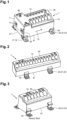
figure 1 is a perspective view of a distribution block, -
figures 2 to 6 are perspective views of variants of the distribution block, -
figure 7 is a perspective view of a mounting assembly of the distribution block, the distribution block being mounted on a support rail according to a transverse configuration, -
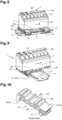
figure 8 is a perspective view of a distribution block with a variant, not forming part of the claimed invention, of the mounting assembly, the terminal block being mount on the support rail according to a longitudinal configuration, -
figure 9 is a perspective view of the distribution block offigure 8 mounted in the transverse configuration, -
figure 10 is a perspective view of the mounting assembly of the distribution block offigures 8 and 9 , -
figure 11 is an inside view of the distribution block, -
figures 12 to 15 are perspective views of variants of a conductive entity of the distribution block. - In the following detailed description of the figures defined above, the same elements or the elements that are fulfilling identical functions may retain the same references so as to simplify the understanding of the invention.
- As illustrated in
figures 1 to 7 , adistribution block 1 is configured to cooperate with asupport rail 3 extending according to asupport direction 5. - The
distribution block 1 is provided with an insulatinghousing 7, a conductingentity 9 included in the insulatinghousing 7 as shown onfigure 11 , at least oneconductor inlet 11 formed in the insulatinghousing 7 and a plurality ofconductor outlets 13 formed in the insulatinghousing 7 and organized in one or several rows. - Said one or several rows are extending substantially parallel to an
extension direction 15 of the insulatinghousing 7. - The
distribution block 1 is also provided with a mountingassembly 17 attached on the insulatinghousing 7 and configured to cooperate with thesupport rail 3. Thedistribution block 1 is arranged to be mounted on thesupport rail 3 according to a longitudinal configuration wherein theextension direction 15 of the insulatinghousing 7 is substantially parallel to thesupport direction 5 as infigure 8 and according to a transverse configuration wherein theextension direction 15 of the insulatinghousing 7 is transverse to thesupport direction 5 as infigures 7 and9 . - The mounting
assembly 17 of thedistribution block 1 can cooperate with thesupport rail 3 according to two different configurations. The insulatinghousing 7 of thedistribution block 1 can be oriented according to thesupport direction 5 or transverse to thesupport direction 5. - The mounting
assembly 17 comprises a snap-fit device 19 configured to cooperate with thesupport rail 3, the snap-fit device 19 comprises a pair ofopposed flanges 21 or a plurality of pairs of opposedflanges 21. - Each
flange 21 of a pair is located on one side of thesupport rail 3 transversally to thesupport direction 5 when the snap-fit device 19 cooperates with thesupport rail 3. - According to the variant of
figures 1 to 7 , the mountingassembly 17 is fixed on the insulatinghousing 7. The snap-fit device 19 comprises a plurality of pairs of opposedflanges 21. - The plurality of pairs of
opposed flanges 21 comprises at least one pair of longitudinal opposed flanges 21a configured to cooperate with thesupport rail 3 in longitudinal configuration and at least one pair of transverse opposed flanges 21b configured to cooperate with thesupport rail 3 in transverse configuration. - In other words, the at least one pair of longitudinal opposed flanges 21a extend according to the
extension direction 15 of the insulatinghousing 7 and the at least one pair of transverse opposed flanges 21b extend transversally. - The at least one pair of transverse opposed flanges 21b are located between the at least one pair of longitudinal opposed flanges 21a transversally to the
extension direction 15 of the insulatinghousing 7. - At least one part of the insulating
housing 7 and the mountingassembly 17 are realized in one piece. Said piece is realized by molding. - Some of the
flanges 21 can be provided withextensions 23 including openings as an alternative fixation means for screws. - According to a variant illustrated on
figures 8 to 10 , the mountingassembly 17 is configured to be mounted on the insulatinghousing 7 in a longitudinal position when in longitudinal configuration and in transverse position when in transverse configuration. - The mounting
assembly 17 is provided with ribs and/orgrooves 25 configured to cooperate with complementary longitudinal grooves and/orribs 27 of the insulatinghousing 7 in longitudinal position and configured to cooperate with complementary transverse grooves and/orribs 29 of the insulatinghousing 7 in transverse position. - The ribs and/or
grooves 25 of the mountingassembly 17 define at least one right angle corner. - The ribs and/or
grooves 25 are profiled and extend according to a mountingdirection 30. The right angle corner is defined by a profile of a rib of the ribs and/orgrooves 25. - The ribs and/or
grooves 25 are configured to engender inverted T-shaped profiledrecesses 32 extending according to the mountingdirection 30 and configured to cooperate with a complementary construction of the insulatinghousing 7. - The mounting
assembly 17 comprises several distinct parts. Here in particular, the mountingassembly 17 comprises two parts. The several distinct parts are profiled parts as disclosed onfigure 10 . - For all the variants as illustrated in
figures 1 to 10 , the mountingassembly 17 comprises arelease mechanism 31 configured to disengage the snap-fit device 19. The mounting assembly can compriseseveral release mechanisms 31. - The
release mechanism 31 comprises a biasing element 33 configured to displace at least one part of aflange 21, the biasing element 33 comprising a lever configured to be displaced by hand and/or by a tool to be inserted in adedicated housing 34. - For example, the lever comprises a
slit 35 for the insertion of the tool as a screwdriver. According to another possibility, the biasing element 33 includes a counter spring 37 configured to maintain the at least one part of theflange 21 in cooperation with thesupport rail 3. - The insulating
housing 7 presents a pluggingside 39 on which the plurality ofconductor outlets 13 are located and a connectingside 41 on which the mountingassembly 17 is attached. - The plugging
side 39 and the connectingside 41 are opposed according to anormal direction 43 of the insulatinghousing 7 that is substantially perpendicular to theextension direction 15 of the insulatinghousing 7. - The mounting
assembly 17 is located between the connectingside 41 and thesupport rail 3 when thedistribution block 1 cooperates with thesupport rail 3. - As also shown on
figures 11 to 15 , thedistribution block 1 comprises an inlet screwedmechanism 45 configured to connect a conductor installed in the at least oneconductor inlet 11. - According to one possibility, the
distribution block 1 comprises oneconductor inlet 11 and the inlet screwedmechanism 45 comprises one screw accessible from the outside of the insulatinghousing 7. - According to another possibility, the
distribution block 1 comprises twoconductor inlets 11 and the inlet screwedmechanism 45 comprises two corresponding screws accessible from the outside of the insulatinghousing 7. - The at least one
conductor inlet 11 is located on anend side 47 of the insulatinghousing 7, theend side 47 extending transversally to theextension direction 15 of the insulatinghousing 7. - The at least one conductor inlet insertion direction is substantially perpendicular to each insertion direction of the plurality of conductor inlets.
- According to a first possibility, the at least one conductor inlet insertion is substantially orthogonal to the extension plane of the
end side 47. - According to a second possibility, the at least one conductor inlet insertion is substantially longitudinal to the extension plane of the
end side 47. In this case, the insulatinghousing 7 comprises a corresponding inlet casing 49 extending from the extension plane of theend side 47. - As shown on
figures 11 to 15 , thedistribution block 1 comprises a push-in mechanism 51 including a leaf spring 53 for eachconductor outlet 13, the insulatinghousing 7 having for eachconductor outlet 13 anactuating opening 55 for displacing said leaf spring 53 as shown onfigures 8 and 9 . - At least a part the plurality of
conductor outlets 13 and corresponding leaf springs 53 have different sizes adapted to receive different sized conductors. - For example, a first group of
conductor outlets 13 is adapted to a first conductor size and a second group ofconductor outlets 13 is adapted to a second conductor size that is bigger. - As shown on
figure 13 , the leaf springs 53 of the push-in mechanism 51 can be realized in one piece. According to another possibility, theconductive entity 9 and leaf springs 53 can constitute a single piece in brass. - According to another possibility, the leaf springs 53 can be independent springs configured to cooperate with the
conductive entity 9 as infigures 12 and 14 . - The
conductive entity 9 can comprise a metal sheet that is cut and folded as infigures 12 and 13 or a machined metal block as infigures 13 and 15 . - As a conclusion, the different variants of the
distribution block 1 can be installed on thesupport rail 3 in two different ways. It simplifies the handling of the distribution blocks 1 in terms of stock and part references. Thedistribution block 1 can also be displaced when already wired if there is a need of place for another part to be installed on thesupport rail 3.
Claims (11)
- Distribution block (1) configured to cooperate with a support rail (3) extending according to a support direction (5), the distribution block (1) being provided with:- an insulating housing (7),- a conducting entity (9) included in the insulating housing (7),- at least one conductor inlet (11) formed in the insulating housing (7),- a plurality of conductor outlets (13) formed in the insulating housing (7) and organized in one or several rows, said one or several rows extending substantially parallel to an extension direction (15) of the insulating housing (7),- a mounting assembly (17) attached on the insulating housing (7) and configured to cooperate with the support rail (3), the distribution block (1) being arranged to be mounted on the support rail (3) according to a longitudinal configuration wherein the extension direction (15) of the insulating housing (7) is substantially parallel to the support direction (5) and according to a transverse configuration wherein the extension direction (15) of the insulating housing is transverse to the support direction (5),wherein the mounting assembly (17) comprises a snap-fit device (19) configured to cooperate with the support rail (3), the snap-fit device (19) comprises a plurality of pairs of opposed flanges (21),wherein the mounting assembly (17) is fixed on the insulating housing (7) and said plurality of pairs of opposed flanges (21) comprises at least one pair of longitudinal opposed flanges (21a) configured to cooperate with the support rail (3) in longitudinal configuration and at least one pair of transverse opposed flanges (21b) configured to cooperate with the support rail (3) in transverse configuration,characterised in that the at least one pair of transverse opposed flanges (21b) are located between the at least one pair of longitudinal opposed flanges (21a) transversally to the extension direction (15) of the insulating housing (7).
- Distribution block (1) according to claim 1, wherein at least one part of the insulating housing (7) and the mounting assembly (17) are realized in one piece.
- Distribution block (1) according to one of the claims 1 or 2, wherein the mounting assembly (17) comprises a release mechanism (31) configured to disengage the snap-fit device (19).
- Distribution block (1) according to claim 3, wherein the release mechanism (31) comprises a biasing element (33) configured to displace at least one part of a flange (21), the biasing element (33) comprising a lever configured to be displaced by hand and/or by a tool.
- Distribution block (1) according to one of the claims 1 to 4, wherein the insulating housing (7) presents a plugging side (39) on which the plurality of conductor outlets (13) are located and a connecting side (41) on which the mounting assembly (17) is attached, the plugging side (39) and the connecting side (41) being opposed according to a normal direction (43) of the insulating housing (7) that is substantially perpendicular to the extension direction (15) of the insulating housing (7).
- Distribution block (1) according to one of the claims 1 to 5, comprising an inlet screwed mechanism (45) configured to connect a conductor installed in the at least one conductor inlet (11).
- Distribution block (1) according to one of the claims 1 to 6, wherein the at least one conductor inlet (11) is located on an end side (47) of the insulating housing (7), the end side (47) extending transversally to the extension direction (15) of the insulating housing (7).
- Distribution block (1) according to one of the claims 1 to 7, comprising a push-in mechanism (51) including a leaf spring (53) for each conductor outlet (13), the insulating housing (7) having for each conductor outlet (13) an actuating opening (55) for displacing said leaf spring (53).
- Distribution block (1) according to claim 8, wherein at least a part the plurality of conductor outlets (13) and corresponding leaf springs (53) have different sizes adapted to receive different sized conductors.
- Distribution block (1) according to one of the claims 8 or 9, wherein at least a part of the leaf springs (53) of the push-in mechanism (51) are realized in one piece.
- Distribution block (1) according to one of the claims 1 to 10, wherein the conductive entity (9) comprises a metal sheet that is cut and folded or a machined metal block.
Priority Applications (3)
| Application Number | Priority Date | Filing Date | Title |
|---|---|---|---|
| EP20306299.7A EP3993170B1 (en) | 2020-10-30 | 2020-10-30 | Distribution block cooperating with a support rail in longitudinal configuration and in transverse configuration |
| US17/510,860 US11777236B2 (en) | 2020-10-30 | 2021-10-26 | Distribution block |
| CN202111254165.8A CN114447720B (en) | 2020-10-30 | 2021-10-27 | Distribution block cooperating with support rail in a longitudinal and transverse configuration |
Applications Claiming Priority (1)
| Application Number | Priority Date | Filing Date | Title |
|---|---|---|---|
| EP20306299.7A EP3993170B1 (en) | 2020-10-30 | 2020-10-30 | Distribution block cooperating with a support rail in longitudinal configuration and in transverse configuration |
Publications (2)
| Publication Number | Publication Date |
|---|---|
| EP3993170A1 EP3993170A1 (en) | 2022-05-04 |
| EP3993170B1 true EP3993170B1 (en) | 2024-06-12 |
Family
ID=73288542
Family Applications (1)
| Application Number | Title | Priority Date | Filing Date |
|---|---|---|---|
| EP20306299.7A Active EP3993170B1 (en) | 2020-10-30 | 2020-10-30 | Distribution block cooperating with a support rail in longitudinal configuration and in transverse configuration |
Country Status (3)
| Country | Link |
|---|---|
| US (1) | US11777236B2 (en) |
| EP (1) | EP3993170B1 (en) |
| CN (1) | CN114447720B (en) |
Family Cites Families (28)
| Publication number | Priority date | Publication date | Assignee | Title |
|---|---|---|---|---|
| DE2126869A1 (en) * | 1971-05-29 | 1972-11-30 | Wieland Elektrische Industrie | Fixing device for switchgear terminal blocks |
| FR2385244A1 (en) * | 1976-10-15 | 1978-10-20 | Alsthom Cgee | JUNCTION BLOCK WITH TWO FIXING ORIENTATIONS |
| DE7639373U1 (en) * | 1976-12-16 | 1977-03-24 | C. A. Weidmueller Kg, 4930 Detmold | Terminal arrangement |
| DE3014755A1 (en) * | 1980-04-17 | 1981-10-22 | C.A. Weidmüller KG, 4930 Detmold | MIXABLE BLOCK FOR ELECTRICAL CONNECTORS |
| US5480310A (en) * | 1993-10-28 | 1996-01-02 | Raychem Corporation | Connector ground clip |
| DE29806691U1 (en) * | 1998-04-15 | 1998-05-28 | Weidmüller Interface GmbH & Co, 32760 Detmold | Mounting foot for modular housing or clamps |
| US6431880B1 (en) | 1998-06-22 | 2002-08-13 | Cooper Technologies | Modular terminal fuse block |
| US6431909B1 (en) * | 2000-09-28 | 2002-08-13 | Rockwell Automation Technologies, Inc. | DIN rail attachment method and apparatus |
| DE102004032864A1 (en) * | 2004-07-06 | 2006-02-16 | Hager Electro Gmbh | Distributor of the electrical installation |
| US7396262B2 (en) | 2004-12-10 | 2008-07-08 | Cooper Technologies Company | Sealed compact power distribution module |
| FR2879833B1 (en) * | 2004-12-16 | 2008-06-13 | Schneider Electric Ind Sas | DEVICE FOR LOCKING AN ELECTRICAL APPARATUS ON A SUPPORT RAIL |
| DE102007051647B4 (en) * | 2007-10-26 | 2009-12-10 | Friedrich Göhringer Elektrotechnik GmbH | A busbar assembly |
| DE202010005215U1 (en) * | 2010-04-15 | 2010-07-29 | Hora-Werk Gmbh | Electrical connection device |
| US8379398B2 (en) * | 2011-03-23 | 2013-02-19 | Phoenix Contact Development & Manufacturing, Inc. | DIN rail mountable base for process fieldbus redundant power conditioner |
| DE102011017702A1 (en) * | 2011-04-28 | 2012-10-31 | Zumtobel Lighting Gmbh | Trunking system and converter unit for this |
| DE102011112120B4 (en) * | 2011-09-02 | 2018-04-05 | Phoenix Contact Gmbh & Co. Kg | Device with several block terminals |
| KR20140103280A (en) | 2011-11-23 | 2014-08-26 | 쓰리엠 이노베이티브 프로퍼티즈 컴파니 | Electrical connector |
| US9303811B1 (en) * | 2014-02-11 | 2016-04-05 | Cisco Technology, Inc. | Configurable mounting bracket for mounting rail installations |
| CA2892220C (en) * | 2014-06-30 | 2021-01-26 | Matthew Rain Darr | Pluggable touch-safe fuse module with built-in removal handle |
| CN204046995U (en) * | 2014-09-09 | 2014-12-24 | 泰科电子(上海)有限公司 | Mounting brackets and control equipment |
| DE202015100696U1 (en) * | 2015-02-12 | 2016-05-13 | Weidmüller Interface GmbH & Co. KG | Arrangement of several locking feet for an assembly and assembly |
| PT3061367T (en) * | 2015-02-25 | 2019-04-22 | Hmy Group | System for supplying and distributing electricity and configured to equip a shelving device |
| DE102015218108B4 (en) * | 2015-09-21 | 2017-06-01 | Ellenberger & Poensgen Gmbh | switchgear |
| US10490927B2 (en) * | 2017-08-16 | 2019-11-26 | Minghu BAO | Self-enclosed electrical assembly with wire crimping structure |
| CN208157658U (en) * | 2018-03-27 | 2018-11-27 | 菲尼克斯亚太电气(南京)有限公司 | A kind of bolt terminal |
| EP3588710A1 (en) * | 2018-06-29 | 2020-01-01 | Tyco Electronics Services GmbH | Power distribution block assembly with easily removable knockouts |
| DE102018127715A1 (en) * | 2018-11-07 | 2020-05-07 | Phoenix Contact Gmbh & Co. Kg | Track system |
| US11463083B2 (en) * | 2019-10-04 | 2022-10-04 | Lear Corporation | Electrical system |
-
2020
- 2020-10-30 EP EP20306299.7A patent/EP3993170B1/en active Active
-
2021
- 2021-10-26 US US17/510,860 patent/US11777236B2/en active Active
- 2021-10-27 CN CN202111254165.8A patent/CN114447720B/en active Active
Also Published As
| Publication number | Publication date |
|---|---|
| EP3993170A1 (en) | 2022-05-04 |
| US20220140503A1 (en) | 2022-05-05 |
| US11777236B2 (en) | 2023-10-03 |
| CN114447720A (en) | 2022-05-06 |
| CN114447720B (en) | 2024-05-10 |
Similar Documents
| Publication | Publication Date | Title |
|---|---|---|
| JP3688338B2 (en) | Electrical connection and coupling terminal | |
| KR100910100B1 (en) | Terminal device of electrical apparatus | |
| JP6440714B2 (en) | Holding frame for plug-in connector, method for manufacturing the same, and method for inserting modules | |
| EP3474383B1 (en) | Din rail installing portion structure of electrical appliance and socket | |
| US6333846B1 (en) | Power supply shut-off apparatus | |
| US5493085A (en) | Spring clip assembly for electrical connections to flat stabs and switches incorporating the same | |
| US6794979B2 (en) | Fuse holder assembly | |
| US20090258532A1 (en) | Module having terminals for actuators and/or sensors | |
| EP1187996A2 (en) | Terminal connector for a circuit breaker | |
| US6102750A (en) | Self-retaining spring clip assembly and an electrical connection incorporating the same | |
| CN113097771A (en) | Holding frame for a plug connector | |
| US6039612A (en) | Arrangement for mounting terminal blocks in a mounting panel | |
| MXPA01010756A (en) | Low profile combination switch and connector assembly. | |
| JP4925974B2 (en) | Drawer type circuit breaker, terminal device of drawer type circuit breaker, and interphase insulating plate of terminal device | |
| US7372692B2 (en) | Electrical enclosure and interior assembly therefor | |
| US6430036B1 (en) | Electrical housing with non-integral cable outlet port member | |
| EP3993170A1 (en) | Distribution block cooperating with a support rail in longitudinal configuration and in transverse configuration | |
| US11056847B2 (en) | Fastening clamp | |
| CN107431285A (en) | Junction box with external electrical components | |
| US20080102714A1 (en) | Service switching device and connection terminal for a service switching device | |
| CN102347545B (en) | Electrical installation device | |
| US20200395691A1 (en) | Conductor terminal, assortment of at least one base module and differently designed conductor connecting modules of a conductor terminal, and conductor terminal block | |
| EP0156389B1 (en) | Pull out fusible switches | |
| CN109659202B (en) | Plug-in neutral connector for use with a fault circuit interrupter | |
| US6577495B2 (en) | Fuse base assembly |
Legal Events
| Date | Code | Title | Description |
|---|---|---|---|
| PUAI | Public reference made under article 153(3) epc to a published international application that has entered the european phase |
Free format text: ORIGINAL CODE: 0009012 |
|
| STAA | Information on the status of an ep patent application or granted ep patent |
Free format text: STATUS: THE APPLICATION HAS BEEN PUBLISHED |
|
| AK | Designated contracting states |
Kind code of ref document: A1 Designated state(s): AL AT BE BG CH CY CZ DE DK EE ES FI FR GB GR HR HU IE IS IT LI LT LU LV MC MK MT NL NO PL PT RO RS SE SI SK SM TR |
|
| STAA | Information on the status of an ep patent application or granted ep patent |
Free format text: STATUS: REQUEST FOR EXAMINATION WAS MADE |
|
| 17P | Request for examination filed |
Effective date: 20221021 |
|
| RBV | Designated contracting states (corrected) |
Designated state(s): AL AT BE BG CH CY CZ DE DK EE ES FI FR GB GR HR HU IE IS IT LI LT LU LV MC MK MT NL NO PL PT RO RS SE SI SK SM TR |
|
| GRAP | Despatch of communication of intention to grant a patent |
Free format text: ORIGINAL CODE: EPIDOSNIGR1 |
|
| STAA | Information on the status of an ep patent application or granted ep patent |
Free format text: STATUS: GRANT OF PATENT IS INTENDED |
|
| RIC1 | Information provided on ipc code assigned before grant |
Ipc: H01R 9/26 20060101AFI20231221BHEP |
|
| INTG | Intention to grant announced |
Effective date: 20240117 |
|
| GRAS | Grant fee paid |
Free format text: ORIGINAL CODE: EPIDOSNIGR3 |
|
| GRAA | (expected) grant |
Free format text: ORIGINAL CODE: 0009210 |
|
| STAA | Information on the status of an ep patent application or granted ep patent |
Free format text: STATUS: THE PATENT HAS BEEN GRANTED |
|
| AK | Designated contracting states |
Kind code of ref document: B1 Designated state(s): AL AT BE BG CH CY CZ DE DK EE ES FI FR GB GR HR HU IE IS IT LI LT LU LV MC MK MT NL NO PL PT RO RS SE SI SK SM TR |
|
| REG | Reference to a national code |
Ref country code: GB Ref legal event code: FG4D |
|
| REG | Reference to a national code |
Ref country code: CH Ref legal event code: EP |
|
| REG | Reference to a national code |
Ref country code: DE Ref legal event code: R096 Ref document number: 602020032258 Country of ref document: DE |
|
| REG | Reference to a national code |
Ref country code: IE Ref legal event code: FG4D |
|
| PG25 | Lapsed in a contracting state [announced via postgrant information from national office to epo] |
Ref country code: BG Free format text: LAPSE BECAUSE OF FAILURE TO SUBMIT A TRANSLATION OF THE DESCRIPTION OR TO PAY THE FEE WITHIN THE PRESCRIBED TIME-LIMIT Effective date: 20240612 |
|
| PG25 | Lapsed in a contracting state [announced via postgrant information from national office to epo] |
Ref country code: FI Free format text: LAPSE BECAUSE OF FAILURE TO SUBMIT A TRANSLATION OF THE DESCRIPTION OR TO PAY THE FEE WITHIN THE PRESCRIBED TIME-LIMIT Effective date: 20240612 Ref country code: HR Free format text: LAPSE BECAUSE OF FAILURE TO SUBMIT A TRANSLATION OF THE DESCRIPTION OR TO PAY THE FEE WITHIN THE PRESCRIBED TIME-LIMIT Effective date: 20240612 |
|
| REG | Reference to a national code |
Ref country code: LT Ref legal event code: MG9D |
|
| PG25 | Lapsed in a contracting state [announced via postgrant information from national office to epo] |
Ref country code: GR Free format text: LAPSE BECAUSE OF FAILURE TO SUBMIT A TRANSLATION OF THE DESCRIPTION OR TO PAY THE FEE WITHIN THE PRESCRIBED TIME-LIMIT Effective date: 20240913 |
|
| REG | Reference to a national code |
Ref country code: NL Ref legal event code: MP Effective date: 20240612 |
|
| PG25 | Lapsed in a contracting state [announced via postgrant information from national office to epo] |
Ref country code: ES Free format text: LAPSE BECAUSE OF FAILURE TO SUBMIT A TRANSLATION OF THE DESCRIPTION OR TO PAY THE FEE WITHIN THE PRESCRIBED TIME-LIMIT Effective date: 20240612 |
|
| PG25 | Lapsed in a contracting state [announced via postgrant information from national office to epo] |
Ref country code: LV Free format text: LAPSE BECAUSE OF FAILURE TO SUBMIT A TRANSLATION OF THE DESCRIPTION OR TO PAY THE FEE WITHIN THE PRESCRIBED TIME-LIMIT Effective date: 20240612 |
|
| PG25 | Lapsed in a contracting state [announced via postgrant information from national office to epo] |
Ref country code: NO Free format text: LAPSE BECAUSE OF FAILURE TO SUBMIT A TRANSLATION OF THE DESCRIPTION OR TO PAY THE FEE WITHIN THE PRESCRIBED TIME-LIMIT Effective date: 20240912 Ref country code: LV Free format text: LAPSE BECAUSE OF FAILURE TO SUBMIT A TRANSLATION OF THE DESCRIPTION OR TO PAY THE FEE WITHIN THE PRESCRIBED TIME-LIMIT Effective date: 20240612 Ref country code: HR Free format text: LAPSE BECAUSE OF FAILURE TO SUBMIT A TRANSLATION OF THE DESCRIPTION OR TO PAY THE FEE WITHIN THE PRESCRIBED TIME-LIMIT Effective date: 20240612 Ref country code: GR Free format text: LAPSE BECAUSE OF FAILURE TO SUBMIT A TRANSLATION OF THE DESCRIPTION OR TO PAY THE FEE WITHIN THE PRESCRIBED TIME-LIMIT Effective date: 20240913 Ref country code: FI Free format text: LAPSE BECAUSE OF FAILURE TO SUBMIT A TRANSLATION OF THE DESCRIPTION OR TO PAY THE FEE WITHIN THE PRESCRIBED TIME-LIMIT Effective date: 20240612 Ref country code: ES Free format text: LAPSE BECAUSE OF FAILURE TO SUBMIT A TRANSLATION OF THE DESCRIPTION OR TO PAY THE FEE WITHIN THE PRESCRIBED TIME-LIMIT Effective date: 20240612 Ref country code: BG Free format text: LAPSE BECAUSE OF FAILURE TO SUBMIT A TRANSLATION OF THE DESCRIPTION OR TO PAY THE FEE WITHIN THE PRESCRIBED TIME-LIMIT Effective date: 20240612 Ref country code: RS Free format text: LAPSE BECAUSE OF FAILURE TO SUBMIT A TRANSLATION OF THE DESCRIPTION OR TO PAY THE FEE WITHIN THE PRESCRIBED TIME-LIMIT Effective date: 20240912 |
|
| PG25 | Lapsed in a contracting state [announced via postgrant information from national office to epo] |
Ref country code: NL Free format text: LAPSE BECAUSE OF FAILURE TO SUBMIT A TRANSLATION OF THE DESCRIPTION OR TO PAY THE FEE WITHIN THE PRESCRIBED TIME-LIMIT Effective date: 20240612 |
|
| REG | Reference to a national code |
Ref country code: AT Ref legal event code: MK05 Ref document number: 1695019 Country of ref document: AT Kind code of ref document: T Effective date: 20240612 |
|
| REG | Reference to a national code |
Ref country code: DE Ref legal event code: R081 Ref document number: 602020032258 Country of ref document: DE Owner name: TE CONNECTIVITY SOLUTIONS GMBH, CH Free format text: FORMER OWNERS: TE CONNECTIVITY INDIA PRIVATE LIMITED, BANGALORE, IN; TYCO ELECTRONICS FRANCE SAS, PONTOISE, FR Ref country code: DE Ref legal event code: R081 Ref document number: 602020032258 Country of ref document: DE Owner name: TE CONNECTIVITY INDIA PRIVATE LIMITED, IN Free format text: FORMER OWNERS: TE CONNECTIVITY INDIA PRIVATE LIMITED, BANGALORE, IN; TYCO ELECTRONICS FRANCE SAS, PONTOISE, FR |
|
| PG25 | Lapsed in a contracting state [announced via postgrant information from national office to epo] |
Ref country code: NL Free format text: LAPSE BECAUSE OF FAILURE TO SUBMIT A TRANSLATION OF THE DESCRIPTION OR TO PAY THE FEE WITHIN THE PRESCRIBED TIME-LIMIT Effective date: 20240612 |
|
| REG | Reference to a national code |
Ref country code: GB Ref legal event code: 732E Free format text: REGISTERED BETWEEN 20241114 AND 20241120 |
|
| PG25 | Lapsed in a contracting state [announced via postgrant information from national office to epo] |
Ref country code: PT Free format text: LAPSE BECAUSE OF FAILURE TO SUBMIT A TRANSLATION OF THE DESCRIPTION OR TO PAY THE FEE WITHIN THE PRESCRIBED TIME-LIMIT Effective date: 20241014 |
|
| PG25 | Lapsed in a contracting state [announced via postgrant information from national office to epo] |
Ref country code: PT Free format text: LAPSE BECAUSE OF FAILURE TO SUBMIT A TRANSLATION OF THE DESCRIPTION OR TO PAY THE FEE WITHIN THE PRESCRIBED TIME-LIMIT Effective date: 20241014 |
|
| PG25 | Lapsed in a contracting state [announced via postgrant information from national office to epo] |
Ref country code: PL Free format text: LAPSE BECAUSE OF FAILURE TO SUBMIT A TRANSLATION OF THE DESCRIPTION OR TO PAY THE FEE WITHIN THE PRESCRIBED TIME-LIMIT Effective date: 20240612 |
|
| PG25 | Lapsed in a contracting state [announced via postgrant information from national office to epo] |
Ref country code: EE Free format text: LAPSE BECAUSE OF FAILURE TO SUBMIT A TRANSLATION OF THE DESCRIPTION OR TO PAY THE FEE WITHIN THE PRESCRIBED TIME-LIMIT Effective date: 20240612 |
|
| PG25 | Lapsed in a contracting state [announced via postgrant information from national office to epo] |
Ref country code: IS Free format text: LAPSE BECAUSE OF FAILURE TO SUBMIT A TRANSLATION OF THE DESCRIPTION OR TO PAY THE FEE WITHIN THE PRESCRIBED TIME-LIMIT Effective date: 20241012 Ref country code: AT Free format text: LAPSE BECAUSE OF FAILURE TO SUBMIT A TRANSLATION OF THE DESCRIPTION OR TO PAY THE FEE WITHIN THE PRESCRIBED TIME-LIMIT Effective date: 20240612 |
|
| PG25 | Lapsed in a contracting state [announced via postgrant information from national office to epo] |
Ref country code: CZ Free format text: LAPSE BECAUSE OF FAILURE TO SUBMIT A TRANSLATION OF THE DESCRIPTION OR TO PAY THE FEE WITHIN THE PRESCRIBED TIME-LIMIT Effective date: 20240612 |
|
| PG25 | Lapsed in a contracting state [announced via postgrant information from national office to epo] |
Ref country code: RO Free format text: LAPSE BECAUSE OF FAILURE TO SUBMIT A TRANSLATION OF THE DESCRIPTION OR TO PAY THE FEE WITHIN THE PRESCRIBED TIME-LIMIT Effective date: 20240612 Ref country code: SK Free format text: LAPSE BECAUSE OF FAILURE TO SUBMIT A TRANSLATION OF THE DESCRIPTION OR TO PAY THE FEE WITHIN THE PRESCRIBED TIME-LIMIT Effective date: 20240612 |
|
| PG25 | Lapsed in a contracting state [announced via postgrant information from national office to epo] |
Ref country code: SM Free format text: LAPSE BECAUSE OF FAILURE TO SUBMIT A TRANSLATION OF THE DESCRIPTION OR TO PAY THE FEE WITHIN THE PRESCRIBED TIME-LIMIT Effective date: 20240612 |
|
| PG25 | Lapsed in a contracting state [announced via postgrant information from national office to epo] |
Ref country code: SM Free format text: LAPSE BECAUSE OF FAILURE TO SUBMIT A TRANSLATION OF THE DESCRIPTION OR TO PAY THE FEE WITHIN THE PRESCRIBED TIME-LIMIT Effective date: 20240612 Ref country code: SK Free format text: LAPSE BECAUSE OF FAILURE TO SUBMIT A TRANSLATION OF THE DESCRIPTION OR TO PAY THE FEE WITHIN THE PRESCRIBED TIME-LIMIT Effective date: 20240612 Ref country code: RO Free format text: LAPSE BECAUSE OF FAILURE TO SUBMIT A TRANSLATION OF THE DESCRIPTION OR TO PAY THE FEE WITHIN THE PRESCRIBED TIME-LIMIT Effective date: 20240612 Ref country code: PL Free format text: LAPSE BECAUSE OF FAILURE TO SUBMIT A TRANSLATION OF THE DESCRIPTION OR TO PAY THE FEE WITHIN THE PRESCRIBED TIME-LIMIT Effective date: 20240612 Ref country code: IS Free format text: LAPSE BECAUSE OF FAILURE TO SUBMIT A TRANSLATION OF THE DESCRIPTION OR TO PAY THE FEE WITHIN THE PRESCRIBED TIME-LIMIT Effective date: 20241012 Ref country code: EE Free format text: LAPSE BECAUSE OF FAILURE TO SUBMIT A TRANSLATION OF THE DESCRIPTION OR TO PAY THE FEE WITHIN THE PRESCRIBED TIME-LIMIT Effective date: 20240612 Ref country code: CZ Free format text: LAPSE BECAUSE OF FAILURE TO SUBMIT A TRANSLATION OF THE DESCRIPTION OR TO PAY THE FEE WITHIN THE PRESCRIBED TIME-LIMIT Effective date: 20240612 Ref country code: AT Free format text: LAPSE BECAUSE OF FAILURE TO SUBMIT A TRANSLATION OF THE DESCRIPTION OR TO PAY THE FEE WITHIN THE PRESCRIBED TIME-LIMIT Effective date: 20240612 |
|
| PG25 | Lapsed in a contracting state [announced via postgrant information from national office to epo] |
Ref country code: IT Free format text: LAPSE BECAUSE OF FAILURE TO SUBMIT A TRANSLATION OF THE DESCRIPTION OR TO PAY THE FEE WITHIN THE PRESCRIBED TIME-LIMIT Effective date: 20240612 |
|
| REG | Reference to a national code |
Ref country code: DE Ref legal event code: R097 Ref document number: 602020032258 Country of ref document: DE |
|
| PG25 | Lapsed in a contracting state [announced via postgrant information from national office to epo] |
Ref country code: DK Free format text: LAPSE BECAUSE OF FAILURE TO SUBMIT A TRANSLATION OF THE DESCRIPTION OR TO PAY THE FEE WITHIN THE PRESCRIBED TIME-LIMIT Effective date: 20240612 |
|
| PLBE | No opposition filed within time limit |
Free format text: ORIGINAL CODE: 0009261 |
|
| STAA | Information on the status of an ep patent application or granted ep patent |
Free format text: STATUS: NO OPPOSITION FILED WITHIN TIME LIMIT |
|
| 26N | No opposition filed |
Effective date: 20250313 |
|
| REG | Reference to a national code |
Ref country code: CH Ref legal event code: PL |
|
| PG25 | Lapsed in a contracting state [announced via postgrant information from national office to epo] |
Ref country code: MC Free format text: LAPSE BECAUSE OF FAILURE TO SUBMIT A TRANSLATION OF THE DESCRIPTION OR TO PAY THE FEE WITHIN THE PRESCRIBED TIME-LIMIT Effective date: 20240612 |
|
| PG25 | Lapsed in a contracting state [announced via postgrant information from national office to epo] |
Ref country code: BE Free format text: LAPSE BECAUSE OF NON-PAYMENT OF DUE FEES Effective date: 20241031 Ref country code: LU Free format text: LAPSE BECAUSE OF NON-PAYMENT OF DUE FEES Effective date: 20241030 |
|
| PG25 | Lapsed in a contracting state [announced via postgrant information from national office to epo] |
Ref country code: CH Free format text: LAPSE BECAUSE OF NON-PAYMENT OF DUE FEES Effective date: 20241031 |
|
| REG | Reference to a national code |
Ref country code: BE Ref legal event code: MM Effective date: 20241031 |
|
| PG25 | Lapsed in a contracting state [announced via postgrant information from national office to epo] |
Ref country code: SE Free format text: LAPSE BECAUSE OF FAILURE TO SUBMIT A TRANSLATION OF THE DESCRIPTION OR TO PAY THE FEE WITHIN THE PRESCRIBED TIME-LIMIT Effective date: 20240612 |
|
| PGFP | Annual fee paid to national office [announced via postgrant information from national office to epo] |
Ref country code: GB Payment date: 20250911 Year of fee payment: 6 |
|
| PGFP | Annual fee paid to national office [announced via postgrant information from national office to epo] |
Ref country code: FR Payment date: 20250908 Year of fee payment: 6 |
|
| PG25 | Lapsed in a contracting state [announced via postgrant information from national office to epo] |
Ref country code: IE Free format text: LAPSE BECAUSE OF NON-PAYMENT OF DUE FEES Effective date: 20241030 |
|
| PGFP | Annual fee paid to national office [announced via postgrant information from national office to epo] |
Ref country code: DE Payment date: 20250902 Year of fee payment: 6 |
|
| PG25 | Lapsed in a contracting state [announced via postgrant information from national office to epo] |
Ref country code: HU Free format text: LAPSE BECAUSE OF FAILURE TO SUBMIT A TRANSLATION OF THE DESCRIPTION OR TO PAY THE FEE WITHIN THE PRESCRIBED TIME-LIMIT; INVALID AB INITIO Effective date: 20201030 |
|
| PG25 | Lapsed in a contracting state [announced via postgrant information from national office to epo] |
Ref country code: CY Free format text: LAPSE BECAUSE OF FAILURE TO SUBMIT A TRANSLATION OF THE DESCRIPTION OR TO PAY THE FEE WITHIN THE PRESCRIBED TIME-LIMIT; INVALID AB INITIO Effective date: 20201030 |