EP3992956A1 - Interior upright for runway guidance sign - Google Patents
Interior upright for runway guidance sign Download PDFInfo
- Publication number
- EP3992956A1 EP3992956A1 EP21205099.1A EP21205099A EP3992956A1 EP 3992956 A1 EP3992956 A1 EP 3992956A1 EP 21205099 A EP21205099 A EP 21205099A EP 3992956 A1 EP3992956 A1 EP 3992956A1
- Authority
- EP
- European Patent Office
- Prior art keywords
- housing
- guidance sign
- interior
- runway
- upright
- Prior art date
- Legal status (The legal status is an assumption and is not a legal conclusion. Google has not performed a legal analysis and makes no representation as to the accuracy of the status listed.)
- Pending
Links
Images



Classifications
-
- G—PHYSICS
- G09—EDUCATION; CRYPTOGRAPHY; DISPLAY; ADVERTISING; SEALS
- G09F—DISPLAYING; ADVERTISING; SIGNS; LABELS OR NAME-PLATES; SEALS
- G09F19/00—Advertising or display means not otherwise provided for
- G09F19/22—Advertising or display means on roads, walls or similar surfaces, e.g. illuminated
- G09F19/228—Ground signs, i.e. display signs fixed on the ground
-
- G—PHYSICS
- G09—EDUCATION; CRYPTOGRAPHY; DISPLAY; ADVERTISING; SEALS
- G09F—DISPLAYING; ADVERTISING; SIGNS; LABELS OR NAME-PLATES; SEALS
- G09F13/00—Illuminated signs; Luminous advertising
- G09F13/04—Signs, boards or panels, illuminated from behind the insignia
- G09F13/0413—Frames or casing structures therefor
-
- B—PERFORMING OPERATIONS; TRANSPORTING
- B64—AIRCRAFT; AVIATION; COSMONAUTICS
- B64F—GROUND OR AIRCRAFT-CARRIER-DECK INSTALLATIONS SPECIALLY ADAPTED FOR USE IN CONNECTION WITH AIRCRAFT; DESIGNING, MANUFACTURING, ASSEMBLING, CLEANING, MAINTAINING OR REPAIRING AIRCRAFT, NOT OTHERWISE PROVIDED FOR; HANDLING, TRANSPORTING, TESTING OR INSPECTING AIRCRAFT COMPONENTS, NOT OTHERWISE PROVIDED FOR
- B64F1/00—Ground or aircraft-carrier-deck installations
- B64F1/36—Other airport installations
-
- B—PERFORMING OPERATIONS; TRANSPORTING
- B64—AIRCRAFT; AVIATION; COSMONAUTICS
- B64F—GROUND OR AIRCRAFT-CARRIER-DECK INSTALLATIONS SPECIALLY ADAPTED FOR USE IN CONNECTION WITH AIRCRAFT; DESIGNING, MANUFACTURING, ASSEMBLING, CLEANING, MAINTAINING OR REPAIRING AIRCRAFT, NOT OTHERWISE PROVIDED FOR; HANDLING, TRANSPORTING, TESTING OR INSPECTING AIRCRAFT COMPONENTS, NOT OTHERWISE PROVIDED FOR
- B64F1/00—Ground or aircraft-carrier-deck installations
- B64F1/002—Taxiing aids
-
- G—PHYSICS
- G09—EDUCATION; CRYPTOGRAPHY; DISPLAY; ADVERTISING; SEALS
- G09F—DISPLAYING; ADVERTISING; SIGNS; LABELS OR NAME-PLATES; SEALS
- G09F13/00—Illuminated signs; Luminous advertising
- G09F13/04—Signs, boards or panels, illuminated from behind the insignia
-
- G—PHYSICS
- G09—EDUCATION; CRYPTOGRAPHY; DISPLAY; ADVERTISING; SEALS
- G09F—DISPLAYING; ADVERTISING; SIGNS; LABELS OR NAME-PLATES; SEALS
- G09F13/00—Illuminated signs; Luminous advertising
- G09F13/04—Signs, boards or panels, illuminated from behind the insignia
- G09F13/0418—Constructional details
- G09F13/0472—Traffic signs
Definitions
- the present disclosure generally relates to an interior upright for runway guidance sign.
- Guidance signs are designed for use on airport runways to mark taxi routes and/or taxiways/runways intersections.
- colors may be black on yellow, yellow on black, or white on red depending on the application as defined by the governing standards such as FAA AC 150/5345-44K.
- a conventional guidance sign may include a generally rectangular housing having opposite upper and lower walls, opposite side walls, and a rear wall.
- the upper, lower, and side walls define an opening at a front side in which a sign panel is received.
- An interior upright within the housing extends between the upper and lower walls to provide upright to the upper wall.
- the interior upright being made of multiple components formed separately and fastened to one another using fasteners.
- a runway guidance sign generally comprises a housing defining an interior space and an opening at a front side.
- the housing includes opposite upper and lower walls.
- An interior upright is received in the interior space of the housing.
- the interior upright is fastened to and extends between the upper and lower walls.
- the interior upright is integrally formed from a one-piece sheet of material.
- an interior upright for a runway guidance sign having a housing with upper and lower walls generally comprises a vertical body that is generally planar.
- the vertical body has opposite side faces and upper and lower ends.
- At least one upper fastening tab extends outward from at least one of the opposite side faces at the upper end of the vertical body.
- the at least one upper fastening tab is configured to be fastened to the upper wall of the housing of the runway guidance sign.
- At least one lower fastening tab extends outward from at least one of the opposite side faces at the lower end of the vertical body.
- the at least one lower fastening tab is configured to be fastened to the lower wall of the housing of the runway guidance sign.
- the interior upright is sized and shaped to be disposed between the upper and lower walls of the housing of the runway guidance sign and provide load-bearing support to the upper wall.
- the interior upright is integrally formed from a one-piece sheet of material.
- a method of making a runway guidance sign generally comprises forming a housing defining an interior space and an opening at a front side.
- the housing includes opposite upper and lower walls.
- the method further comprises forming an interior upright from a one-piece sheet of metal.
- the interior upright includes a vertical body that is generally planar.
- the vertical body has opposite side faces and upper and lower ends.
- At least one upper fastening tab extends outward from at least one of the opposite side faces at the upper end of the vertical body.
- At least one lower fastening tab extends outward from at least one of the opposite side faces at the lower end of the vertical body.
- the method further comprises fastening the at least one upper fastening tab to the upper wall of the housing within the interior space of the housing, and fastening the at least one lower fastening tab to the lower wall of the housing within the interior space of the housing.
- the runway guidance sign 10 includes a housing, generally indicated at 12, defining an interior space 14 and an opening at a front side 16.
- the illustrated housing 10 includes upper and lower walls 20, 22, opposite side walls, 24, 26, and a rear wall or panel 28.
- the walls 20, 22, 24, 26, respectively may be formed from thin sheets of metal and secured to one another using, such as by fasteners (e.g., nuts and bolts and/or screws) and/or welding.
- Flanges extend inward from the upper, lower, and side walls 20, 22, 24, 26, respectively, to define the opening at the front side 16.
- At least one suitable runway sign panel 30 one panel is broken away in FIG.
- the runway guidance sign 10 further includes one or more feet 36, e.g., four feet as illustrated, to elevate the sign above the runway.
- the interior upright 34 includes a body 40 having a height H, and upper and lower fastening tabs or flanges 42, 44, respectively, at corresponding upper and lower ends of the body.
- the body 40 is elongate and generally flat or planar.
- the body 40 has opposite planar side faces 46, 48 and opposite front and rear ends 50, 52.
- the upper and lower ends and the front and rear ends 50, 52, respectively, of the body 40 define recesses 56 (e.g., cutouts) to provide clearances for structures within the interior space 14 of the housing 12 and/or facilitate bending or folding of the upright 34 during manufacturing, as explained below.
- the fastening tabs 42, 44 define fastener openings 60 configured to receive a fastener (e.g., a screw or bolt) for securing the interior upright 34 in the housing 12.
- a fastener e.g., a screw or bolt
- the upper fastening tabs 42 are used to secure the upright 34 to the upper wall 20
- the lower fastening tabs 44 are used to secure the upright to the lower wall 22.
- the upright 34 includes four upper fastening tabs 42 (two left fastening tabs and two right fastening tabs) and four lower fastening tabs 44 (two left fastening tabs and two right fastening tabs).
- the upright 34 may include other suitable numbers of fastening tabs 42, 44 suitable for fastening the upright in the housing 12. As shown in FIGS.
- planar side faces 46, 48 are generally parallel to the side walls 24, 26 of the housing 12 and extend between the rear wall 28 and the front side 16 of the housing (and the sign panel 30).
- the upright 34 is generally centered in the housing 12 and is suitable for providing load-bearing support to the upper wall 20.
- the upright 34 is integrally formed from a single sheet of material (e.g., a single sheet of metal).
- the single sheet of material includes first and second halves that are mirror images of one another about a vertical fold line FL ( FIG. 4 ). That is, the first and second halves are symmetrical about the vertical fold line FL.
- the sheet of material is bent or folded about the fold line FL such that the first and second halves are folded over one another to form the upright 34.
- the fold line FL is at the one of the front and rear ends 50, 52 and spaced apart living hinges are formed at the corresponding one of the front and rear ends 50, 52.
- the fastening tabs 42, 44 are bent out of plane so that they extend outward from the respective side faces 46, 48 of the body 40.
- the upright may be formed in other ways.
- the runway guidance sign 100 is similar to the first runway guidance sign 10, except it is longer than the first runway guidance sign and is suitable for a longer sign panel 130.
- the guidance sign 100 includes two interior uprights 134 spaced at 1/3 and 2/3 of the length of the guidance sign to provide suitable load-bearing support to the upper wall 120 of the housing 112.
- the guidance sign may have other lengths and any number of interior uprights suitable for providing load-bearing support to the upper wall.
Landscapes
- Engineering & Computer Science (AREA)
- Physics & Mathematics (AREA)
- General Physics & Mathematics (AREA)
- Theoretical Computer Science (AREA)
- Mechanical Engineering (AREA)
- Aviation & Aerospace Engineering (AREA)
- Business, Economics & Management (AREA)
- Accounting & Taxation (AREA)
- Marketing (AREA)
- Road Signs Or Road Markings (AREA)
Abstract
Description
- This application claims priority to
U.S. Provisional Patent Application Serial No. 63/106,234, filed October 27, 2020 - The present disclosure generally relates to an interior upright for runway guidance sign.
- Guidance signs are designed for use on airport runways to mark taxi routes and/or taxiways/runways intersections. As an example, colors may be black on yellow, yellow on black, or white on red depending on the application as defined by the governing standards such as FAA AC 150/5345-44K. A conventional guidance sign may include a generally rectangular housing having opposite upper and lower walls, opposite side walls, and a rear wall. The upper, lower, and side walls define an opening at a front side in which a sign panel is received. An interior upright within the housing extends between the upper and lower walls to provide upright to the upper wall. The interior upright being made of multiple components formed separately and fastened to one another using fasteners.
- In one aspect, a runway guidance sign generally comprises a housing defining an interior space and an opening at a front side. The housing includes opposite upper and lower walls. An interior upright is received in the interior space of the housing. The interior upright is fastened to and extends between the upper and lower walls. The interior upright is integrally formed from a one-piece sheet of material.
- In another aspect, an interior upright for a runway guidance sign having a housing with upper and lower walls generally comprises a vertical body that is generally planar. The vertical body has opposite side faces and upper and lower ends. At least one upper fastening tab extends outward from at least one of the opposite side faces at the upper end of the vertical body. The at least one upper fastening tab is configured to be fastened to the upper wall of the housing of the runway guidance sign. At least one lower fastening tab extends outward from at least one of the opposite side faces at the lower end of the vertical body. The at least one lower fastening tab is configured to be fastened to the lower wall of the housing of the runway guidance sign. The interior upright is sized and shaped to be disposed between the upper and lower walls of the housing of the runway guidance sign and provide load-bearing support to the upper wall. The interior upright is integrally formed from a one-piece sheet of material.
- In yet another aspect, a method of making a runway guidance sign generally comprises forming a housing defining an interior space and an opening at a front side. The housing includes opposite upper and lower walls. The method further comprises forming an interior upright from a one-piece sheet of metal. The interior upright includes a vertical body that is generally planar. The vertical body has opposite side faces and upper and lower ends. At least one upper fastening tab extends outward from at least one of the opposite side faces at the upper end of the vertical body. At least one lower fastening tab extends outward from at least one of the opposite side faces at the lower end of the vertical body. The method further comprises fastening the at least one upper fastening tab to the upper wall of the housing within the interior space of the housing, and fastening the at least one lower fastening tab to the lower wall of the housing within the interior space of the housing.
-
-
FIG. 1 is a perspective of a guidance sign including an interior upright within an interior of a housing of the guidance sign. -
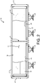
FIG. 2 is a front elevation of the guidance sign. -
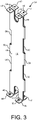
FIG. 3 is an enlarged perspective of the interior upright removed from the guidance sign. -
FIG. 4 is a front elevation of the interior upright. -
FIG. 5 is a bottom plan view of the interior upright. -
FIG. 6 is a top plan view of the interior upright. -
FIG. 7 is a perspective of another embodiment of a guidance sign including two interior uprights. -
FIG. 8 is a front elevation of the guidance sign ofFIG. 7 . - Referring to
FIGS. 1 and2 , an illustrated embodiment of a runway guidance sign is indicated generally byreference numeral 10. Therunway guidance sign 10 includes a housing, generally indicated at 12, defining aninterior space 14 and an opening at afront side 16. In particular, the illustratedhousing 10 includes upper andlower walls walls side walls front side 16. At least one suitable runway sign panel 30 (one panel is broken away inFIG. 2 ) is secured to thehousing 12 at thefront side 16 behind the flanges of thewalls interior space 14 of the housing, as is generally known in the art. An interior upright, generally indicated at 34, received in theinterior space 14 is configured to provide load-bearing support to theupper wall 20. Details of the interior upright 34 are described below. A lighting source 35 (FIG. 2 ), such as one or more light emitting diodes, are received in theinterior space 14 to backlight the sign panel, as is also generally known in the art. Thelighting source 35 may be attached to theupper wall 20. Therunway guidance sign 10 further includes one ormore feet 36, e.g., four feet as illustrated, to elevate the sign above the runway. - Referring to
FIGS. 3-6 , the interior upright 34 includes abody 40 having a height H, and upper and lower fastening tabs orflanges body 40 is elongate and generally flat or planar. Thebody 40 has oppositeplanar side faces rear ends rear ends body 40 define recesses 56 (e.g., cutouts) to provide clearances for structures within theinterior space 14 of thehousing 12 and/or facilitate bending or folding of the upright 34 during manufacturing, as explained below. Thefastening tabs fastener openings 60 configured to receive a fastener (e.g., a screw or bolt) for securing the interior upright 34 in thehousing 12. In particular, theupper fastening tabs 42 are used to secure the upright 34 to theupper wall 20, and thelower fastening tabs 44 are used to secure the upright to thelower wall 22. In the illustrated embodiment, the upright 34 includes four upper fastening tabs 42 (two left fastening tabs and two right fastening tabs) and four lower fastening tabs 44 (two left fastening tabs and two right fastening tabs). The upright 34 may include other suitable numbers of fasteningtabs housing 12. As shown inFIGS. 1 and2 , as secured in thehousing 12, the planar side faces 46, 48 are generally parallel to theside walls housing 12 and extend between the rear wall 28 and thefront side 16 of the housing (and the sign panel 30). InFIGS. 1 and2 , the upright 34 is generally centered in thehousing 12 and is suitable for providing load-bearing support to theupper wall 20. - In the illustrated embodiment, the upright 34 is integrally formed from a single sheet of material (e.g., a single sheet of metal). In particular, the single sheet of material includes first and second halves that are mirror images of one another about a vertical fold line FL (
FIG. 4 ). That is, the first and second halves are symmetrical about the vertical fold line FL. The sheet of material is bent or folded about the fold line FL such that the first and second halves are folded over one another to form theupright 34. When formed, the fold line FL is at the one of the front andrear ends rear ends fastening tabs body 40. The upright may be formed in other ways. - Referring to
FIGS. 7 and8 , another embodiment of a runway guidance sign is generally indicated at 100. Therunway guidance sign 100 is similar to the firstrunway guidance sign 10, except it is longer than the first runway guidance sign and is suitable for a longer sign panel 130. In this embodiment, theguidance sign 100 includes twointerior uprights 134 spaced at 1/3 and 2/3 of the length of the guidance sign to provide suitable load-bearing support to the upper wall 120 of thehousing 112. In other embodiments, the guidance sign may have other lengths and any number of interior uprights suitable for providing load-bearing support to the upper wall. - Modifications and variations of the disclosed embodiments are possible without departing from the scope of the invention defined in the appended claims.
- When introducing elements of the present invention or the embodiment(s) thereof, the articles "a", "an", "the" and "said" are intended to mean that there are one or more of the elements. The terms "comprising", "including" and "having" are intended to be inclusive and mean that there may be additional elements other than the listed elements.
- As various changes could be made in the above constructions, products, and methods without departing from the scope of the invention, it is intended that all matter contained in the above description and shown in the accompanying drawings shall be interpreted as illustrative and not in a limiting sense.
Claims (15)
- A runway guidance sign comprising:a housing defining an interior space and an opening at a front side, the housing includes opposite upper and lower walls; andan interior upright received in the interior space of the housing, the interior upright fastened to and extending between the upper and lower walls, wherein the interior upright is integrally formed from a one-piece sheet of material.
- The runway guidance sign set forth in claim 1, wherein interior upright includes a vertical body having first and second halves folded over one another about a fold line.
- The runway guidance sign set forth in claim 2, further comprising a rear wall and a runway guidance sign panel opposing the rear wall and secured to the housing at the front side to enclose the interior space.
- The runway guidance sign set forth in claim 3, wherein the interior upright is disposed between the rear wall and the runway guidance sign panel.
- The runway guidance sign set forth in claim 2, wherein the first and second halves are mirror images of one another.
- The runway guidance sign set forth in claim 1, wherein the interior upright includes a generally planar vertical body, and upper and lower fastening tabs extending outward out of plane from upper and lower ends of the generally planar vertical body, and wherein the upper and lower fastening tabs are secured to the corresponding upper and lower walls of the housing.
- The runway guidance sign set forth in claim 1, wherein the interior upright is integrally formed from a one-piece sheet of metal.
- The runway guidance sign set forth in claim 1, further comprising a runway guidance sign panel secured to the housing at the front side, a light source within the interior space of the housing and configured to backlight the runway guidance sign panel, and at least one foot secured to the lower wall of the housing and configured to elevate the housing about a runway.
- The runway guidance sign set forth in claim 1, wherein the housing further includes opposite side walls extending between the upper and lower walls, and a rear wall.
- An interior upright for a runway guidance sign having a housing with upper and lower walls, the interior upright comprising:a vertical body that is generally planar, the vertical body having opposite side faces and upper and lower ends;at least one upper fastening tab extending outward from at least one of the opposite side faces at the upper end of the vertical body, the at least one upper fastening tab configured to be fastened to the upper wall of the housing of the runway guidance sign; andat least one lower fastening tab extending outward from at least one of the opposite side faces at the lower end of the vertical body, the at least one lower fastening tab configured to be fastened to the lower wall of the housing of the runway guidance sign,wherein the interior upright is sized and shaped to be disposed between the upper and lower walls of the housing of the runway guidance sign and provide load-bearing support to the upper wall,wherein the interior upright is integrally formed from a one-piece sheet of material.
- The interior upright set forth in claim 10, vertical body has first and second planar halves folded over one another about a fold line.
- The interior upright set forth in claim 11, wherein the first and second halves are mirror images of one another.
- The interior upright set forth in claim 11, wherein the interior upright is integrally formed from a one-piece sheet of metal.
- A method of making a runway guidance sign comprising:forming a housing defining an interior space and an opening at a front side, the housing including opposite upper and lower walls;forming an interior upright from a one-piece sheet of metal, the interior upright includinga vertical body that is generally planar, the vertical body having opposite side faces and upper and lower ends,at least one upper fastening tab extending outward from at least one of the opposite side faces at the upper end of the vertical body, andat least one lower fastening tab extending outward from at least one of the opposite side faces at the lower end of the vertical body;fastening the at least one upper fastening tab to the upper wall of the housing within the interior space of the housing; andfastening the at least one lower fastening tab to the lower wall of the housing within the interior space of the housing.
- The method of making a runway guidance sign set forth in claim 14, wherein said forming the interior upright comprises folding the one-piece sheet of metal about a fold line, and wherein said forming the interior upright comprises folding the at least one upper and lower fastening tabs out of plane relative to the vertical body.
Applications Claiming Priority (1)
| Application Number | Priority Date | Filing Date | Title |
|---|---|---|---|
| US202063106234P | 2020-10-27 | 2020-10-27 |
Publications (1)
| Publication Number | Publication Date |
|---|---|
| EP3992956A1 true EP3992956A1 (en) | 2022-05-04 |
Family
ID=78414253
Family Applications (1)
| Application Number | Title | Priority Date | Filing Date |
|---|---|---|---|
| EP21205099.1A Pending EP3992956A1 (en) | 2020-10-27 | 2021-10-27 | Interior upright for runway guidance sign |
Country Status (5)
| Country | Link |
|---|---|
| US (1) | US11798442B2 (en) |
| EP (1) | EP3992956A1 (en) |
| CN (1) | CN114506468A (en) |
| CA (1) | CA3136091A1 (en) |
| MX (1) | MX2021013128A (en) |
Citations (3)
| Publication number | Priority date | Publication date | Assignee | Title |
|---|---|---|---|---|
| KR200415027Y1 (en) * | 2006-02-15 | 2006-04-26 | 이강원 | Car License Plate Light Emitting Device |
| US7134764B1 (en) * | 2004-11-04 | 2006-11-14 | Roger Bieberdorf | Airport light system |
| US20110023338A1 (en) * | 2009-07-31 | 2011-02-03 | Ellerton Andrew B | Airport Guidance Sign Illuminated with Cylindrical LED Arrays |
Family Cites Families (8)
| Publication number | Priority date | Publication date | Assignee | Title |
|---|---|---|---|---|
| US3390259A (en) * | 1966-02-07 | 1968-06-25 | Marshall Youngman S | Illuminated sign |
| US4287555A (en) * | 1978-03-10 | 1981-09-01 | Johann Stilling | Strut raceways for sign boxes |
| US4331270A (en) * | 1980-10-15 | 1982-05-25 | Wald Manufacturing Company | Bicycle basket |
| US7377062B2 (en) * | 2006-03-01 | 2008-05-27 | Ellerton Andrew B | Curved face airport guidance sign |
| US7244042B1 (en) * | 2006-10-21 | 2007-07-17 | Roger Bieberdorf | Airport light system |
| RU77082U1 (en) * | 2008-05-16 | 2008-10-10 | Закрытое акционерное общество "Еврознак АГ Санкт-Петербург" | ROAD SIGN PANEL |
| CN204477827U (en) * | 2015-04-07 | 2015-07-15 | 湖南汇博电子技术有限公司 | Mark indicating lamp |
| US20180212116A1 (en) * | 2017-01-17 | 2018-07-26 | Astronics Dme Llc | Durable LED Light Engine for Airfield Guidance Sign |
-
2021
- 2021-10-26 MX MX2021013128A patent/MX2021013128A/en unknown
- 2021-10-26 US US17/452,384 patent/US11798442B2/en active Active
- 2021-10-27 EP EP21205099.1A patent/EP3992956A1/en active Pending
- 2021-10-27 CA CA3136091A patent/CA3136091A1/en active Pending
- 2021-10-27 CN CN202111253235.8A patent/CN114506468A/en active Pending
Patent Citations (3)
| Publication number | Priority date | Publication date | Assignee | Title |
|---|---|---|---|---|
| US7134764B1 (en) * | 2004-11-04 | 2006-11-14 | Roger Bieberdorf | Airport light system |
| KR200415027Y1 (en) * | 2006-02-15 | 2006-04-26 | 이강원 | Car License Plate Light Emitting Device |
| US20110023338A1 (en) * | 2009-07-31 | 2011-02-03 | Ellerton Andrew B | Airport Guidance Sign Illuminated with Cylindrical LED Arrays |
Also Published As
| Publication number | Publication date |
|---|---|
| US11798442B2 (en) | 2023-10-24 |
| US20220130290A1 (en) | 2022-04-28 |
| MX2021013128A (en) | 2022-04-28 |
| CN114506468A (en) | 2022-05-17 |
| CA3136091A1 (en) | 2022-04-27 |
Similar Documents
| Publication | Publication Date | Title |
|---|---|---|
| US4570787A (en) | Display device | |
| US9867483B2 (en) | Signage systems and merchandising display assemblies | |
| US4911311A (en) | Display stand with vertically stacked trays | |
| US11744388B2 (en) | Product display system and method | |
| US6612090B1 (en) | Non-combustible panel wall system | |
| BR9509117A (en) | Container made essentially of one or more sheets of film and process for its manufacture | |
| GB2078680A (en) | Containers for freight transport | |
| US3260022A (en) | Paperboard arches | |
| BRPI1104877A2 (en) | AUXILIARY VISUAL MARKING PLATE FOR DEFENSES OR BARRIERS AND METHOD FOR MARKING DEFENSES | |
| US11798442B2 (en) | Interior upright for runway guidance sign | |
| US20070246398A1 (en) | Pallet system for product display | |
| US4276706A (en) | Post and panel sign assembly | |
| US6588134B1 (en) | Hanging sign and method | |
| EP1006846A1 (en) | Protective cover with integrally formed display stand | |
| EP0656445A1 (en) | Foldable and transportable beacon for traffic signalling for emergency use on public roadways and other uses | |
| US1890682A (en) | Self-supported display device | |
| CN205831551U (en) | Wall is shown in a kind of aluminium section bar exhibition art show | |
| KR200300011Y1 (en) | A Sign Board For Safety On Set-Up/Separation | |
| US2072698A (en) | Toy building | |
| EP0841029A2 (en) | Display shelf system | |
| CN2778871Y (en) | Movable netty grate shelf | |
| KR20060029790A (en) | Assembly method and structure of signboard frame | |
| KR102783779B1 (en) | Direction indicator for guardrail | |
| DE4110183A1 (en) | ADVERTISING MEDIA | |
| AU2021103332A4 (en) | Box sign |
Legal Events
| Date | Code | Title | Description |
|---|---|---|---|
| PUAI | Public reference made under article 153(3) epc to a published international application that has entered the european phase |
Free format text: ORIGINAL CODE: 0009012 |
|
| STAA | Information on the status of an ep patent application or granted ep patent |
Free format text: STATUS: REQUEST FOR EXAMINATION WAS MADE |
|
| 17P | Request for examination filed |
Effective date: 20211027 |
|
| AK | Designated contracting states |
Kind code of ref document: A1 Designated state(s): AL AT BE BG CH CY CZ DE DK EE ES FI FR GB GR HR HU IE IS IT LI LT LU LV MC MK MT NL NO PL PT RO RS SE SI SK SM TR |
|
| P01 | Opt-out of the competence of the unified patent court (upc) registered |
Effective date: 20230521 |
|
| STAA | Information on the status of an ep patent application or granted ep patent |
Free format text: STATUS: EXAMINATION IS IN PROGRESS |
|
| 17Q | First examination report despatched |
Effective date: 20240429 |
|
| GRAP | Despatch of communication of intention to grant a patent |
Free format text: ORIGINAL CODE: EPIDOSNIGR1 |
|
| STAA | Information on the status of an ep patent application or granted ep patent |
Free format text: STATUS: GRANT OF PATENT IS INTENDED |
|
| INTG | Intention to grant announced |
Effective date: 20260410 |