EP3992942A1 - Methods and systems for determining an attribute of an object at a pre-determined point - Google Patents
Methods and systems for determining an attribute of an object at a pre-determined point Download PDFInfo
- Publication number
- EP3992942A1 EP3992942A1 EP20205090.2A EP20205090A EP3992942A1 EP 3992942 A1 EP3992942 A1 EP 3992942A1 EP 20205090 A EP20205090 A EP 20205090A EP 3992942 A1 EP3992942 A1 EP 3992942A1
- Authority
- EP
- European Patent Office
- Prior art keywords
- image
- points
- data structure
- determined
- implemented method
- Prior art date
- Legal status (The legal status is an assumption and is not a legal conclusion. Google has not performed a legal analysis and makes no representation as to the accuracy of the status listed.)
- Granted
Links
Images



Classifications
-
- G—PHYSICS
- G06—COMPUTING OR CALCULATING; COUNTING
- G06T—IMAGE DATA PROCESSING OR GENERATION, IN GENERAL
- G06T7/00—Image analysis
- G06T7/20—Analysis of motion
- G06T7/246—Analysis of motion using feature-based methods, e.g. the tracking of corners or segments
-
- G—PHYSICS
- G06—COMPUTING OR CALCULATING; COUNTING
- G06V—IMAGE OR VIDEO RECOGNITION OR UNDERSTANDING
- G06V10/00—Arrangements for image or video recognition or understanding
- G06V10/70—Arrangements for image or video recognition or understanding using pattern recognition or machine learning
- G06V10/764—Arrangements for image or video recognition or understanding using pattern recognition or machine learning using classification, e.g. of video objects
-
- G—PHYSICS
- G06—COMPUTING OR CALCULATING; COUNTING
- G06V—IMAGE OR VIDEO RECOGNITION OR UNDERSTANDING
- G06V20/00—Scenes; Scene-specific elements
- G06V20/50—Context or environment of the image
- G06V20/56—Context or environment of the image exterior to a vehicle by using sensors mounted on the vehicle
-
- G—PHYSICS
- G08—SIGNALLING
- G08G—TRAFFIC CONTROL SYSTEMS
- G08G1/00—Traffic control systems for road vehicles
- G08G1/16—Anti-collision systems
- G08G1/167—Driving aids for lane monitoring, lane changing, e.g. blind spot detection
-
- G—PHYSICS
- G06—COMPUTING OR CALCULATING; COUNTING
- G06T—IMAGE DATA PROCESSING OR GENERATION, IN GENERAL
- G06T2207/00—Indexing scheme for image analysis or image enhancement
- G06T2207/20—Special algorithmic details
- G06T2207/20084—Artificial neural networks [ANN]
-
- G—PHYSICS
- G06—COMPUTING OR CALCULATING; COUNTING
- G06T—IMAGE DATA PROCESSING OR GENERATION, IN GENERAL
- G06T2207/00—Indexing scheme for image analysis or image enhancement
- G06T2207/30—Subject of image; Context of image processing
- G06T2207/30241—Trajectory
-
- G—PHYSICS
- G06—COMPUTING OR CALCULATING; COUNTING
- G06T—IMAGE DATA PROCESSING OR GENERATION, IN GENERAL
- G06T2207/00—Indexing scheme for image analysis or image enhancement
- G06T2207/30—Subject of image; Context of image processing
- G06T2207/30248—Vehicle exterior or interior
- G06T2207/30252—Vehicle exterior; Vicinity of vehicle
- G06T2207/30256—Lane; Road marking
-
- G—PHYSICS
- G06—COMPUTING OR CALCULATING; COUNTING
- G06T—IMAGE DATA PROCESSING OR GENERATION, IN GENERAL
- G06T2207/00—Indexing scheme for image analysis or image enhancement
- G06T2207/30—Subject of image; Context of image processing
- G06T2207/30248—Vehicle exterior or interior
- G06T2207/30252—Vehicle exterior; Vicinity of vehicle
- G06T2207/30261—Obstacle
Definitions
- the present disclosure relates to methods and systems for determining an attribute of an object at a pre-determined point.
- Trajectory prediction may be an important task for (at least partially) autonomously driving vehicles.
- commonly used methods for trajectory prediction may be computationally expensive and/or inaccurate.
- the present disclosure provides a computer implemented method, a computer system, a vehicle, and a non-transitory computer readable medium according to the independent claims. Embodiments are given in the subclaims, the description and the drawings.
- the present disclosure is directed at a computer implemented method for determining an attribute of an object at a pre-determined point, the method comprising the following steps performed (in other words: carried out) by computer hardware components: determining data representing a plurality of properties of a plurality of items of a vicinity of the object at a plurality of points along a trajectory of the object; arranging the data in a multi-channel image-like data structure, the multi-channel image-like data structure having a plurality of columns, a plurality of rows, and a plurality of channels, wherein the data is arranged in the image-like data structure, so that each of one of the rows or the columns or the channels of the image-like data structure corresponds to one of the plurality of properties of one of the plurality of items at the plurality of points, and each of one other of the rows or the columns or the channels of the image-like data structure corresponds to one the plurality of properties of the plurality of items at one of the plurality of points, and each of yet one other of the rows or
- the attribute of the object may be a probability of an accident in which the object is involved, a probability of a collision involving the object, a location of the object, a speed of the object, a linear velocity of the object, a rotational speed of the object, a distance of the object to a middle of a lane on which the object is located, a lane driving direction of a lane in which the object is, a type of left and right markings of the lane in which the object is, a condition of the lane in which the object is, a breaking light status of the object, or a turning light status of the object.
- the image-like data structure may have a format (for example data format) of an image. However, if the image-like data structure would be displayed by a method for displaying images, this would not lead to displaying an image showing an actual scene that could be interpreted by a human observer. Rather, the image-like data structure stores information related to properties of various objects (the object (which may also be referred to as the target object) and further objects). For example, each property may be indicated by a number, for example a real number or an integer number in the image-like data representation. It will be understood that the image-like data structure may also be referred to as image-like data representation or as image.
- determining the attribute may be understood as determining the attribute at a time point at which no information is available, neither information related to the object nor information (for example properties) of the other
- the method may solve the problem of machine learning based object trajectory prediction regarding to static driving environment.
- a 2D image-like multi-channel data structure including the lane information and the target dynamic information, the correlation between them can be learned in a machine learning system.
- the method may learn the static context for trajectory prediction.
- the method may utilize understanding of driver behaviour within road lanes by structuring the neural network based on static road feature context information for vehicle trajectory prediction
- the object is a vehicle.
- the items comprise lane markings, road boundaries, guard rails, or barriers.
- the plurality of points comprise past time points, and wherein the pre-determined point is a time point succeeding the plurality of time points; or the plurality of points comprise future time points, and wherein the pre-determined point is a time point preceding the plurality of time points.
- the pre-determined point is a time point preceding the plurality of time points
- this may mean that determining (for example predicting) the attribute may include or may be determining the attribute at a past time point. For example, if future information is available (for which it may be known that a critical situation happened), but past information is not available, then the past information may be estimated to determinate the past information.
- the plurality of points comprise past spatial points along a past trajectory of the object, and wherein the pre-determined point is a location succeeding the plurality of past spatial points; or the plurality of points comprise future spatial points along a future trajectory of the object, and wherein the pre-determined point is a location preceding the plurality of future spatial points.
- the property comprises at least one of an x position, a y position points, a validness flag, a lane marking type flag, or a color flag.
- the pre-determined rule may take image data as input data.
- the pre-determined rule may be a rule which usually operates on images. Since the data representing the properties for the various objects at the various time points is arranged in the image-like data structure, the rule which usually operates on images may be used without modification or with minimum modification (for example to adapt to a number of channels different from 1 or different from 3).
- the pre-determined rule may include or may be a neural network, for example a convolutional neural network (CNN), for example a temporal convolution network (TCN).
- the neural network may be trained with training data comprising a plurality of training images, wherein each training image includes data arranged according to the image-like data structure, and wherein each training image is associated with a training attribute of the object.
- CNN convolutional neural network
- TCN temporal convolution network
- the computer implemented method may further comprise the following step carried out by the computer hardware components: assigning a pre-determined value to an entry of the image-like data structure if a property is not available for the object and the point of time corresponding to the entry.
- the remaining rows may be filled with the pre-determined value.
- the respective entries of the image-like data structure may be filled with the pre-determined value.
- Various embodiments may be applied to collision prediction and/or maneuver prediction and/or future trajectory prediction.
- assisted or autonomous driving for example L2/L3/L4 AD applications
- the ego vehicle needs to plan its action in advance, and to do that, it needs to have information about the road and corresponding markings and the like.
- the computer implemented method may further comprise the following step carried out by the computer hardware components: estimating a potential risk of collision based on the determined attribute and/or determining a trajectory of the object to be followed for autonomous motion (for example for autonomous driving or assisted driving) of the object based on the determined attribute. It has been found that based on the determined attribute, a reliable and efficient estimation of a potential risk of collision and efficient determination of a desired trajectory is possible.
- the computer implemented method may further comprise the following steps carried out by the computer hardware components: determining a maneuver to be executed based on the determined attribute. It has been found that based on the determined attribute, a reliable and efficient determination of a maneuver to be executed may be carried out.
- the maneuver to be executed may include or may be at least one of: accelerating, braking, steering, changing lane to the left, changing lane to the right, outputting a warning indication, switching on hazard warning lights, or activating a horn.
- the method may allow for easy integration with existing trajectory prediction systems to bring the static-context awareness into the system.
- the method may be deployed for highway application in real world system.
- the method may provide a dense and efficient data representation; the image like data structure (which may also be referred to as static-context image) may be very small in practice.
- the method may be extension friendly; guard rail, barrier, road boundaries, etc. may be easily included into the static-context image.
- the method may provide a small and efficient network design.
- the CNN for static-context learning may be very small and shallow, and may thus have only a small computational burden.
- the method may provide a performance improvement compared to other methods.
- the present disclosure is directed at a computer system, said computer system comprising a plurality of computer hardware components configured to carry out several or all steps of the computer implemented method described herein.
- the computer system may comprise a plurality of computer hardware components (for example a processor, for example processing unit or processing network, at least one memory, for example memory unit or memory network, and at least one non-transitory data storage). It will be understood that further computer hardware components may be provided and used for carrying out steps of the computer implemented method in the computer system.
- the non-transitory data storage and/or the memory unit may comprise a computer program for instructing the computer to perform several or all steps or aspects of the computer implemented method described herein, for example using the processing unit and the at least one memory unit.
- the present disclosure is directed at vehicle comprising the computer system as described herein.
- the vehicle further comprises a sensor configured to determine sensor data; wherein the properties are determined based on the sensor data.
- the present disclosure is directed at a non-transitory computer readable medium comprising instructions for carrying out several or all steps or aspects of the computer implemented method described herein.
- the computer readable medium may be configured as: an optical medium, such as a compact disc (CD) or a digital versatile disk (DVD); a magnetic medium, such as a hard disk drive (HDD); a solid state drive (SSD); a read only memory (ROM), such as a flash memory; or the like.
- the computer readable medium may be configured as a data storage that is accessible via a data connection, such as an internet connection.
- the computer readable medium may, for example, be an online data repository or a cloud storage.
- the present disclosure is also directed at a computer program for instructing a computer to perform several or all steps or aspects of the computer implemented method described herein.
- Lane markings and other similar road structures like guard rails, road boundaries, barriers, are the most important road, which may influence the road users' behavior and trajectory. They may represent the traffic rules, and may regulate the road user's individual driving behaviors into systematic patterns. But even for the relatively simply highway road, modeling such behavior of the road user with their driving environment may already not be easy.
- the trajectory prediction may be a necessary component for the lots of safety features and autonomous driving.
- a problem of trajectory prediction may for example be formulated as follows: "The target vehicle is driving fast. Where will it be in e.g. 2 second?"
- Fig. 1A shows an illustration 100 of a vehicle 102 and an arrow 104 indicating the present speed of the vehicle 102. For example, based on given physical properties (like target position, velocity, and/or acceleration) the trajectory of the vehicle 102 may be predicted.
- physical properties like target position, velocity, and/or acceleration
- the dynamic-context may include the interaction between the target and its neighbors.
- Fig. 1B shows an illustration 120 of the vehicle 102 and the arrow 104 indicating the present speed of the vehicle 102. Furthermore, a further vehicle 122 is illustrated to be driving in front of the vehicle 102. Thus, the trajectory of the vehicle 102 may also be influenced by the dynamic context, which may for example include other road users.
- the static context may include the road structure, for example the road in front of the target, which may restrict and regulate the vehicle's future trajectory.
- the road structure for example the road in front of the target, which may restrict and regulate the vehicle's future trajectory.
- a vehicle may be driving straight forward, and if the road in front has a curve, then the prediction system should be able to make the conditional prediction based on the road lane information and predict a realistic curved future trajectory, even when the vehicle does not show any sign of turning yet.
- road information may be properly integrated into a machine-learning based system.
- Fig. 1C shows an illustration 140 of the vehicle 102 and the arrow 104 indicating the present speed of the vehicle 102, and the further vehicle 122 driving in front of the vehicle 102. Furthermore, the road 142 is illustrated. Thus, the trajectory of the vehicle 102 may also be influenced by the static context, which may for example include the road, lanes, or the like. For example, the vehicle 102 may break and keep a safe distance, or change the lane (like indicated by arrow 144).
- a convolutional neural network may be used to learn the correlation between the "road” (for example road structure) and the vehicle trajectory.
- Fig. 2 shows an illustration 200 of a convolutional neural network with a source layer 202, a convolutional kernel 204, and a destination layer 206.
- the static-context for trajectory prediction for highway driving may be learned using machine learning techniques.
- the static-context may cover lane markings, road boundaries, guard rails, barrier, or other similar structures typically seen on the highway.
- a data representation may be provided, which may enable efficient static-context learning using convolutional neural networks (CNN).
- CNN convolutional neural networks
- CNN may be a tool for exploiting the spatial correlation in image-like data, which is why CNNs may be used for object detection and classification in image domain.
- the road structure information and the vehicle trajectory may be presented in a proper way that the CNN can be deployed efficiently for static-context learning.
- a single image row data representation may be built by rasterization. This is explained in Fig. 3 below.
- Other road structures e.g. guard rail, barrier, road boundaries, etc. may be rasterized the same way.
- Fig. 3 shows an illustration 300 of lane marking rasterization according to various embodiments.
- a vehicle 302 and a corresponding coordinate system x,y (in vehicle coordinates) is illustrated.
- a lane marking 304 (with discrete points on the lane marking marked with bold circles) are illustrated.
- rasterization 306 a one row multi-channel image 308 may be determined.
- the image width may be obtained by sampling at discrete longitudinal positions (indicated by the bold circles) along the lane marking 304.
- sampling positions There may be different possibilities to define the sampling positions.
- sampling positions may be defined with a pre-defined distance interval in between.
- the sampling positions may be sampled longitudinally at 0,1,2,3,... meters along the lane marking, and their lateral offsets may be another other features to create the above one-row image.
- the sampling positions may be defined with a pre-defined time interval in between. For example, if the target vehicle's longitudinal velocity is vx, then the sampling positions may be sampled at vx ⁇ t1, vx ⁇ t2, vx ⁇ t3,..., along the marking (for example with equidistant time points t1, t2, t3, ).
- a plurality of image channels of each pixel may store all the useful information of the corresponding sampling point one the lane marking, for example: x position of the points, y position of the points, validness flag of the points, lane marking type flag, color flag. It will be understood that any other information may be integrated as extra channels.
- one lane marking may create a one-row image.
- a multi-lane road with multiply lane markings or boundaries or the like may be rasterized into a 2D multi-channel image, like illustrated in Fig. 4 .
- FIG. 4 shows an illustration 400 of how to rasterize a whole road structure according to various embodiments.
- An image 402 illustrates the road, and the road structure is illustrated including a barrier 404, a first lane marking (LM1), a second lane marking (LM2), a third lane marking (LM3), and a road boundary.
- the properties of each of the barrier 404, the first lane marking (LM1), the second lane marking (LM2), the third lane marking (LM3), and the road boundary may be provided a specific row of the static-context image 406 (for example, the properties of the barrier 406 may go into the first row of the static-context image 406.
- a 2D multi-channel image may be created.
- the image height of the image 406 depends on the number of lane markings or boundaries or barriers or the like.
- a 2 lanes highway with 3 LM may be rasterized into an image with 3 image rows.
- guard rail jersey barrier, road boundary, and the like may be rasterized in the same way.
- the height of the image may be fixed.
- the data structure (of the image 406) may be very compact, and each image row may represent one lane marking, and the image width may represent the range that the lane marking is discretized.
- the multiple channels may store all the information of the sampling points.
- the trajectory information of the target vehicle may be brought together with the static context image 406 to enable the application of CNN for learning, like illustrated in Fig. 5 .
- Fig. 5 shows an illustration 500 of how to represent the complete driving scene (for example in a 2D image-like driving scene representation) according to various embodiments.
- a scenario 502 is illustrated.
- the vehicle's past trajectory 504 may be encoded using a trajectory encoder 506, to generate a latent code 508, which, with a reshape operation 510 may be brought into a one-row image with multiple channels 512.
- a trajectory encoder for the trajectory encoder, the method described in European patent application No. 19202631.8 , which is incorporated herein for all purposes, may be used.
- the one-row image with multiple channels 512 (which represents the target vehicle's past trajectory 504) may be concatenated (514) with the static-context image 406, to obtain a 2D multi-channel image 516 to represent the scene (wherein the bottom row of the 2D multi-channel image 516 may correspond to (or be identical to) the one-row image with multiple channels 512, like illustrated by filling the respective entries in gray.
- the dynamic information of the target vehicle may be encoded with a trajectory encoder, which itself may be a deep neural network, to provide a latent code representation for the target movement.
- This latent code may then be reshaped into a 1 row image, with the same width and depth as the rasterized road structure image. Then a concatenation operation may provide a 2D image which represents the driving scene.
- a trajectory encoder the above reference European patent application No. 19202631.8 describes one such network design, which learns the target's dynamic context.
- the trajectory may be predicted.
- Fig. 6 shows an illustration 600 of an application of the 2D image-like data structure 516 for trajectory prediction according to various embodiments.
- the 2D multi-channel image 516 to represent the scene may provide a small, dense data representation, and may be provided to a deep neural network 602.
- the deep neural network may be a CNN, a CNN plus a LSTM (long short-term memory), a ConvLSTM (convolutional LSTM) or the like.
- the deep neural network 602 may output a predicted future trajectory 604.
- a CNN or a CNN in combination with a RNN, or directly a ConvLSTM may be used as the deep neural network 602.
- Fig. 7 shows an illustration 700 of an example of a road rasterization of a highway according to various embodiments.
- a vehicle 702 is shown on a highway 704.
- Properties of a left boundary may be provided in a first row of the multi-channel image like data structure 706, like illustrated by arrow 708.
- Properties of a first lane marking may be provided in a second row of the multi-channel image like data structure 706, like illustrated by arrow 710.
- Properties of a second lane marking may be provided in a third row of the multi-channel image like data structure 706, like illustrated by arrow 712.
- Properties of a right boundary may be provided in a fourth row of the multi-channel image like data structure 706, like illustrated by arrow 714.
- the road opens a further lane on the right, meaning that the x coordinate of the right boundary increases, like illustrated in the last row of the multi-channel image like data structure 706.
- the following highway lateral movements may be available: keep lane, lane change to the left, and lane change to the right.
- modeling three lanes with four lane markings may be sufficient for highway application, including target lane, adjacent left and right lanes.
- a lane split may mean that before the split the data is filled with 0, including its validness feature, and afterwards, non-zero values (x5, x6, x7, x8, x9, ...) are provided.
- Fig. 8 shows an illustration 800 of an example of a road rasterization of a highway according to various embodiments.
- a vehicle 802 is shown on a highway 804.
- Properties of a left boundary may be provided in a second row of the multi-channel image like data structure 806, like illustrated by arrow 808.
- Properties of a middle lane marking may be provided in a third row of the multi-channel image like data structure 806, like illustrated by arrow 810.
- Properties of a right boundary may be provided in a fourth row of the multi-channel image like data structure 806, like illustrated by arrow 812.
- the merged lane markings can be filled with 0 values (as for example illustrated in the second row of the multi-channel image like data structure 806 in Fig. 8 ).
- Fig. 9 shows a flow diagram 900 illustrating a method for determining an attribute of an object at a pre-determined point according to various embodiments.
- data representing a plurality of properties of a plurality of items of a vicinity of the object at a plurality of points along a trajectory of the object may be determined.
- the data may be arranged in a multi-channel image-like data structure, the multi-channel image-like data structure having a plurality of columns, a plurality of rows, and a plurality of channels, wherein the data is arranged in the image-like data structure, so that each of one of the rows or the columns or the channels of the image-like data structure corresponds to one of the plurality of properties of one of the plurality of items at the plurality of points, and each of one other of the rows or the columns or the channels of the image-like data structure corresponds to one the plurality of properties of the plurality of items at one of the plurality of points, and each of yet one other of the rows or the columns or the channels of the image-like data structure corresponds to the plurality of properties of one of the plurality of items at one of the plurality of points.
- the attribute of the object may be determined at the pre-determined point using a pre-determined rule based on the image-like data structure.
- the object may be a vehicle.
- the items may include or may be lane markings, road boundaries, guard rails, or barriers.
- the plurality of points may include or may be past time points, and wherein the pre-determined point is a time point succeeding the plurality of time points; or the plurality of points may include or may be future time points, and wherein the pre-determined point is a time point preceding the plurality of time points.
- the plurality of points may include or may be past spatial points along a past trajectory of the object, and wherein the pre-determined point is a location succeeding the plurality of past spatial points; or the plurality of points may include or may be future spatial points along a future trajectory of the object, and wherein the pre-determined point is a location preceding the plurality of future spatial points.
- the property may include or may be at least one of an x position, a y position points, a validness flag, a lane marking type flag, or a color flag.
- the pre-determined rule may take image data as input data.
- the pre-determined rule may include or may be a neural network.
- the computer implemented method may further include the following step carried out by the computer hardware components: assigning a pre-determined value to an entry of the image-like data structure if a property is not available for the object and the point corresponding to the entry.
- the computer implemented method may further include the following step carried out by the computer hardware components: estimating a potential risk of collision based on the determined attribute; and/or determining a trajectory of the object to be followed for autonomous motion of the object based on the determined attribute; and/ or determining a maneuver to be executed based on the determined attribute.
- the maneuver to be executed may include or may be at least one of: accelerating, braking, steering, changing lane to the left, changing lane to the right, outputting a warning indication, switching on hazard warning lights, or activating a horn.
- Fig. 10 shows an attribute determination system 1000 according to various embodiments.
- the attribute determination system 1000 may include a data determination circuit 1002, an arranging circuit 1004, and an attribute determination circuit 1006.
- the data determination circuit 1002 may be configured to determine data representing a plurality of properties of a plurality of items of a vicinity of an object at a plurality of points along a trajectory of the object.
- the arranging circuit 1004 may be configured to arrange the data in a multi-channel image-like data structure, the multi-channel image-like data structure having a plurality of columns, a plurality of rows, and a plurality of channels, wherein the data is arranged in the image-like data structure, so that each of one of the rows or the columns or the channels of the image-like data structure corresponds to one of the plurality of properties of one of the plurality of items at the plurality of points, and each of one other of the rows or the columns or the channels of the image-like data structure corresponds to one the plurality of properties of the plurality of items at one of the plurality of points, and each of yet one other of the rows or the columns or the channels of the image-like data structure corresponds to the plurality of properties of one of the plurality of items at one of the plurality of points.
- the attribute determination circuit 1006 may be configured to determine the attribute of the object at a pre-determined point using a pre-determined rule based on the image-like data structure.
- the data determination circuit 1002, the arranging circuit 1004, and the attribute determination circuit 1006 may be coupled with each other, e.g. via an electrical connection 1008, such as e.g. a cable or a computer bus or via any other suitable electrical connection to exchange electrical signals.
- an electrical connection 1008 such as e.g. a cable or a computer bus or via any other suitable electrical connection to exchange electrical signals.
- a “circuit” may be understood as any kind of a logic implementing entity, which may be special purpose circuitry or a processor executing a program stored in a memory, firmware, or any combination thereof.
- Fig. 11 shows a computer system 1100 with a plurality of computer hardware components configured to carry out steps of a computer implemented method for determining an attribute of an object at a pre-determined point according to various embodiments.
- the computer system 1100 may include a processor 1102, a memory 1104, and a non-transitory data storage 1106.
- the processor 1102 may carry out instructions provided in the memory 1104.
- the non-transitory data storage 1106 may store a computer program, including the instructions that may be transferred to the memory 1104 and then executed by the processor 1102.
- the processor 1102, the memory 1104, and the non-transitory data storage 1106 may be coupled with each other, e.g. via an electrical connection 1108, such as e.g. a cable or a computer bus or via any other suitable electrical connection to exchange electrical signals.
- an electrical connection 1108, such as e.g. a cable or a computer bus or via any other suitable electrical connection to exchange electrical signals.
- Coupled or “connection” are intended to include a direct “coupling” (for example via a physical link) or direct “connection” as well as an indirect “coupling” or indirect “connection” (for example via a logical link), respectively.
Landscapes
- Engineering & Computer Science (AREA)
- Theoretical Computer Science (AREA)
- General Physics & Mathematics (AREA)
- Physics & Mathematics (AREA)
- Multimedia (AREA)
- Computer Vision & Pattern Recognition (AREA)
- Computing Systems (AREA)
- General Health & Medical Sciences (AREA)
- Medical Informatics (AREA)
- Software Systems (AREA)
- Evolutionary Computation (AREA)
- Databases & Information Systems (AREA)
- Health & Medical Sciences (AREA)
- Artificial Intelligence (AREA)
- Traffic Control Systems (AREA)
- Image Analysis (AREA)
Abstract
Description
- The present disclosure relates to methods and systems for determining an attribute of an object at a pre-determined point.
- Trajectory prediction may be an important task for (at least partially) autonomously driving vehicles. However, commonly used methods for trajectory prediction may be computationally expensive and/or inaccurate.
- Accordingly, there is a need to provide enhanced methods for trajectory prediction.
- The present disclosure provides a computer implemented method, a computer system, a vehicle, and a non-transitory computer readable medium according to the independent claims. Embodiments are given in the subclaims, the description and the drawings.
- In one aspect, the present disclosure is directed at a computer implemented method for determining an attribute of an object at a pre-determined point, the method comprising the following steps performed (in other words: carried out) by computer hardware components: determining data representing a plurality of properties of a plurality of items of a vicinity of the object at a plurality of points along a trajectory of the object; arranging the data in a multi-channel image-like data structure, the multi-channel image-like data structure having a plurality of columns, a plurality of rows, and a plurality of channels, wherein the data is arranged in the image-like data structure, so that each of one of the rows or the columns or the channels of the image-like data structure corresponds to one of the plurality of properties of one of the plurality of items at the plurality of points, and each of one other of the rows or the columns or the channels of the image-like data structure corresponds to one the plurality of properties of the plurality of items at one of the plurality of points, and each of yet one other of the rows or the columns or the channels of the image-like data structure corresponds to the plurality of properties of one of the plurality of items at one of the plurality of points; and determining the attribute of the object at the pre-determined point using a pre-determined rule based on the image-like data structure.
- The attribute of the object may be a probability of an accident in which the object is involved, a probability of a collision involving the object, a location of the object, a speed of the object, a linear velocity of the object, a rotational speed of the object, a distance of the object to a middle of a lane on which the object is located, a lane driving direction of a lane in which the object is, a type of left and right markings of the lane in which the object is, a condition of the lane in which the object is, a breaking light status of the object, or a turning light status of the object.
- The image-like data structure may have a format (for example data format) of an image. However, if the image-like data structure would be displayed by a method for displaying images, this would not lead to displaying an image showing an actual scene that could be interpreted by a human observer. Rather, the image-like data structure stores information related to properties of various objects (the object (which may also be referred to as the target object) and further objects). For example, each property may be indicated by a number, for example a real number or an integer number in the image-like data representation. It will be understood that the image-like data structure may also be referred to as image-like data representation or as image.
- The expression "determining the attribute" may be understood as determining the attribute at a time point at which no information is available, neither information related to the object nor information (for example properties) of the other
- The method may solve the problem of machine learning based object trajectory prediction regarding to static driving environment. By forming a 2D image-like multi-channel data structure including the lane information and the target dynamic information, the correlation between them can be learned in a machine learning system.
- The method may learn the static context for trajectory prediction.
- The method may utilize understanding of driver behaviour within road lanes by structuring the neural network based on static road feature context information for vehicle trajectory prediction
- According to another aspect, the object is a vehicle.
- According to another aspect, the items comprise lane markings, road boundaries, guard rails, or barriers.
- According to another aspect, the plurality of points comprise past time points, and wherein the pre-determined point is a time point succeeding the plurality of time points; or the plurality of points comprise future time points, and wherein the pre-determined point is a time point preceding the plurality of time points.
- When the plurality of points includes future time points, and the pre-determined point is a time point preceding the plurality of time points, this may mean that determining (for example predicting) the attribute may include or may be determining the attribute at a past time point. For example, if future information is available (for which it may be known that a critical situation happened), but past information is not available, then the past information may be estimated to determinate the past information.
- It will be understood that "future" time points are time points after the pre-determined time point and that recorded information is used
- According to another aspect, the plurality of points comprise past spatial points along a past trajectory of the object, and wherein the pre-determined point is a location succeeding the plurality of past spatial points; or the plurality of points comprise future spatial points along a future trajectory of the object, and wherein the pre-determined point is a location preceding the plurality of future spatial points.
- According to another aspect, the property comprises at least one of an x position, a y position points, a validness flag, a lane marking type flag, or a color flag.
- According to another aspect, the pre-determined rule may take image data as input data. In other words, the pre-determined rule may be a rule which usually operates on images. Since the data representing the properties for the various objects at the various time points is arranged in the image-like data structure, the rule which usually operates on images may be used without modification or with minimum modification (for example to adapt to a number of channels different from 1 or different from 3).
- According to another aspect, the pre-determined rule may include or may be a neural network, for example a convolutional neural network (CNN), for example a temporal convolution network (TCN). The neural network may be trained with training data comprising a plurality of training images, wherein each training image includes data arranged according to the image-like data structure, and wherein each training image is associated with a training attribute of the object.
- According to another aspect, the computer implemented method may further comprise the following step carried out by the computer hardware components: assigning a pre-determined value to an entry of the image-like data structure if a property is not available for the object and the point of time corresponding to the entry.
- It has been found that instead of providing several image-like data structures of different sizes (in particular when using neural networks, which have to be trained using training images of a fixed size which is identical to the size of images used during normal operation after training), a single, fixed size of the image-like data structure may be used, and entries (in other words: pixels) of the image-like data structure for which no information is available may be filled with a pre-determined value or flag (for example the value zero ("0")). For example, if the number of further objects is less than the maximum number of further objects that could be represented in the image-like data structure, for example when the number of rows of the image-like data structure is more than the number of further objects plus one (for the target object), the remaining rows (which are not assigned to the object or to any one of the further objects) may be filled with the pre-determined value. For example, if one of the further objects (or the target object) was not observed during a certain period of time, and as such no data representing the property of that further object (or of the target object) is available for the time points corresponding to the certain period of time, the respective entries of the image-like data structure may be filled with the pre-determined value.
- Various embodiments may be applied to collision prediction and/or maneuver prediction and/or future trajectory prediction. For various levels of assisted or autonomous driving (for example L2/L3/L4 AD applications), the ego vehicle needs to plan its action in advance, and to do that, it needs to have information about the road and corresponding markings and the like.
- According to another aspect, the computer implemented method may further comprise the following step carried out by the computer hardware components: estimating a potential risk of collision based on the determined attribute and/or determining a trajectory of the object to be followed for autonomous motion (for example for autonomous driving or assisted driving) of the object based on the determined attribute. It has been found that based on the determined attribute, a reliable and efficient estimation of a potential risk of collision and efficient determination of a desired trajectory is possible.
- According to another aspect, the computer implemented method may further comprise the following steps carried out by the computer hardware components: determining a maneuver to be executed based on the determined attribute. It has been found that based on the determined attribute, a reliable and efficient determination of a maneuver to be executed may be carried out.
- According to another aspect, the maneuver to be executed may include or may be at least one of: accelerating, braking, steering, changing lane to the left, changing lane to the right, outputting a warning indication, switching on hazard warning lights, or activating a horn.
- With the method, a dense, efficient and meaningful data representation for convolutional operation may be provided. The method may allow for easy integration with existing trajectory prediction systems to bring the static-context awareness into the system. The method may be deployed for highway application in real world system.
- The method may provide a dense and efficient data representation; the image like data structure (which may also be referred to as static-context image) may be very small in practice. The method may be extension friendly; guard rail, barrier, road boundaries, etc. may be easily included into the static-context image.
- The method may provide a small and efficient network design. The CNN for static-context learning may be very small and shallow, and may thus have only a small computational burden.
- Together with European patent application No.
19202631.8 - The method may provide a performance improvement compared to other methods.
- In another aspect, the present disclosure is directed at a computer system, said computer system comprising a plurality of computer hardware components configured to carry out several or all steps of the computer implemented method described herein.
- The computer system may comprise a plurality of computer hardware components (for example a processor, for example processing unit or processing network, at least one memory, for example memory unit or memory network, and at least one non-transitory data storage). It will be understood that further computer hardware components may be provided and used for carrying out steps of the computer implemented method in the computer system. The non-transitory data storage and/or the memory unit may comprise a computer program for instructing the computer to perform several or all steps or aspects of the computer implemented method described herein, for example using the processing unit and the at least one memory unit.
- In another aspect, the present disclosure is directed at vehicle comprising the computer system as described herein.
- According to another aspect, the vehicle further comprises a sensor configured to determine sensor data; wherein the properties are determined based on the sensor data.
- In another aspect, the present disclosure is directed at a non-transitory computer readable medium comprising instructions for carrying out several or all steps or aspects of the computer implemented method described herein. The computer readable medium may be configured as: an optical medium, such as a compact disc (CD) or a digital versatile disk (DVD); a magnetic medium, such as a hard disk drive (HDD); a solid state drive (SSD); a read only memory (ROM), such as a flash memory; or the like. Furthermore, the computer readable medium may be configured as a data storage that is accessible via a data connection, such as an internet connection. The computer readable medium may, for example, be an online data repository or a cloud storage.
- The present disclosure is also directed at a computer program for instructing a computer to perform several or all steps or aspects of the computer implemented method described herein.
- Exemplary embodiments and functions of the present disclosure are described herein in conjunction with the following drawings, showing schematically:
- Fig. 1A
- an illustration of a vehicle;
- Fig. 1 B
- an illustration of the vehicle;
- Fig. 1C
- an illustration of the vehicle;
- Fig. 2
- an illustration of a convolutional neural network;
- Fig. 3
- an illustration of lane marking rasterization according to various embodiments;
- Fig. 4
- an illustration of how to rasterize a whole road structure according to various embodiments;
- Fig. 5
- an illustration of how to represent the complete driving scene according to various embodiments;
- Fig. 6
- an illustration of an application of the 2D image-like data structure for trajectory prediction according to various embodiments;
- Fig. 7
- an illustration of an example of a road rasterization of a highway according to various embodiments;
- Fig. 8
- an illustration of an example of a road rasterization of a highway according to various embodiments;
- Fig. 9
- a flow diagram illustrating a method for determining an attribute of an object at a pre-determined point according to various embodiments;
- Fig. 10
- an attribute determination system according to various embodiments; and
- Fig. 11
- a computer system with a plurality of computer hardware components configured to carry out steps of a computer implemented method for determining an attribute of an object at a pre-determined point according to various embodiments.
- Lane markings and other similar road structures like guard rails, road boundaries, barriers, are the most important road, which may influence the road users' behavior and trajectory. They may represent the traffic rules, and may regulate the road user's individual driving behaviors into systematic patterns. But even for the relatively simply highway road, modeling such behavior of the road user with their driving environment may already not be easy. The trajectory prediction may be a necessary component for the lots of safety features and autonomous driving.
- A problem of trajectory prediction may for example be formulated as follows: "The target vehicle is driving fast. Where will it be in e.g. 2 second?"
-
Fig. 1A shows anillustration 100 of avehicle 102 and anarrow 104 indicating the present speed of thevehicle 102. For example, based on given physical properties (like target position, velocity, and/or acceleration) the trajectory of thevehicle 102 may be predicted. - However, it may not only be the physical properties that may have an impact on the trajectory, but also the dynamic context.
- The dynamic-context may include the interaction between the target and its neighbors.
-
Fig. 1B shows anillustration 120 of thevehicle 102 and thearrow 104 indicating the present speed of thevehicle 102. Furthermore, afurther vehicle 122 is illustrated to be driving in front of thevehicle 102. Thus, the trajectory of thevehicle 102 may also be influenced by the dynamic context, which may for example include other road users. - However, it may not only be the physical properties and the dynamic context that may have an impact on the trajectory, but also the static context.
- The static context may include the road structure, for example the road in front of the target, which may restrict and regulate the vehicle's future trajectory. For example, a vehicle may be driving straight forward, and if the road in front has a curve, then the prediction system should be able to make the conditional prediction based on the road lane information and predict a realistic curved future trajectory, even when the vehicle does not show any sign of turning yet. According to various embodiments, such road information may be properly integrated into a machine-learning based system.
-
Fig. 1C shows anillustration 140 of thevehicle 102 and thearrow 104 indicating the present speed of thevehicle 102, and thefurther vehicle 122 driving in front of thevehicle 102. Furthermore, theroad 142 is illustrated. Thus, the trajectory of thevehicle 102 may also be influenced by the static context, which may for example include the road, lanes, or the like. For example, thevehicle 102 may break and keep a safe distance, or change the lane (like indicated by arrow 144). - There may be a strong spatial (for example local) correlation between the future trajectory and static-context. According to various embodiments, an efficient solution to learn such correlation from the data without explicit modeling may be provided.
- According to various embodiments, a convolutional neural network (CNN) may be used to learn the correlation between the "road" (for example road structure) and the vehicle trajectory.
-
Fig. 2 shows anillustration 200 of a convolutional neural network with asource layer 202, aconvolutional kernel 204, and adestination layer 206. - According to various embodiments, the static-context for trajectory prediction for highway driving may be learned using machine learning techniques. The static-context may cover lane markings, road boundaries, guard rails, barrier, or other similar structures typically seen on the highway. According to various embodiments, a data representation may be provided, which may enable efficient static-context learning using convolutional neural networks (CNN).
- It will be understood that the human driver's behaviors and trajectories may have a very strong spatial correlation with its surrounding environment. To mathematically model this correlation may be beyond feasibility because of the huge variations of road structures. At the same time, CNN may be a tool for exploiting the spatial correlation in image-like data, which is why CNNs may be used for object detection and classification in image domain. According to various embodiments, the road structure information and the vehicle trajectory may be presented in a proper way that the CNN can be deployed efficiently for static-context learning.
- Using lane marking as example, according to various embodiments, a single image row data representation may be built by rasterization. This is explained in
Fig. 3 below. Other road structures, e.g. guard rail, barrier, road boundaries, etc. may be rasterized the same way. -
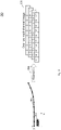
Fig. 3 shows anillustration 300 of lane marking rasterization according to various embodiments. Avehicle 302 and a corresponding coordinate system x,y (in vehicle coordinates) is illustrated. A lane marking 304 (with discrete points on the lane marking marked with bold circles) are illustrated. Byrasterization 306, a one rowmulti-channel image 308 may be determined. - The image width may be obtained by sampling at discrete longitudinal positions (indicated by the bold circles) along the lane marking 304.
- There may be different possibilities to define the sampling positions.
- For example, the sampling positions may be defined with a pre-defined distance interval in between. For example, the sampling positions may be sampled longitudinally at 0,1,2,3,... meters along the lane marking, and their lateral offsets may be another other features to create the above one-row image.
- In another example, the sampling positions may be defined with a pre-defined time interval in between. For example, if the target vehicle's longitudinal velocity is vx, then the sampling positions may be sampled at vx∗t1, vx∗t2, vx∗t3,..., along the marking (for example with equidistant time points t1, t2, t3, ...).
- A plurality of image channels of each pixel may store all the useful information of the corresponding sampling point one the lane marking, for example: x position of the points, y position of the points, validness flag of the points, lane marking type flag, color flag. It will be understood that any other information may be integrated as extra channels.
- As described above, one lane marking may create a one-row image. Similarly, a multi-lane road with multiply lane markings or boundaries or the like may be rasterized into a 2D multi-channel image, like illustrated in
Fig. 4 . -
Fig. 4 shows anillustration 400 of how to rasterize a whole road structure according to various embodiments. Animage 402 illustrates the road, and the road structure is illustrated including abarrier 404, a first lane marking (LM1), a second lane marking (LM2), a third lane marking (LM3), and a road boundary. The properties of each of thebarrier 404, the first lane marking (LM1), the second lane marking (LM2), the third lane marking (LM3), and the road boundary may be provided a specific row of the static-context image 406 (for example, the properties of thebarrier 406 may go into the first row of the static-context image 406. - Thus, with multiple lane markings on the road, a 2D multi-channel image may be created.
- The image height of the
image 406 depends on the number of lane markings or boundaries or barriers or the like. - For example, as illustrated in
Fig. 4 , a 2 lanes highway with 3 LM (lane markings) may be rasterized into an image with 3 image rows. - It will be understood that guard rail, jersey barrier, road boundary, and the like may be rasterized in the same way.
- Because of the semantic definition of each image row, the height of the image may be fixed.
- As can be seen, the data structure (of the image 406) may be very compact, and each image row may represent one lane marking, and the image width may represent the range that the lane marking is discretized. The multiple channels may store all the information of the sampling points.
- According to various embodiments, the trajectory information of the target vehicle may be brought together with the
static context image 406 to enable the application of CNN for learning, like illustrated inFig. 5 . -
Fig. 5 shows anillustration 500 of how to represent the complete driving scene (for example in a 2D image-like driving scene representation) according to various embodiments. - A
scenario 502 is illustrated. The vehicle'spast trajectory 504 may be encoded using atrajectory encoder 506, to generate alatent code 508, which, with a reshapeoperation 510 may be brought into a one-row image withmultiple channels 512. For example, for the trajectory encoder, the method described in European patent application No.19202631.8 context image 406, to obtain a 2Dmulti-channel image 516 to represent the scene (wherein the bottom row of the 2Dmulti-channel image 516 may correspond to (or be identical to) the one-row image withmultiple channels 512, like illustrated by filling the respective entries in gray. - As illustrated in
Fig. 5 , the dynamic information of the target vehicle may be encoded with a trajectory encoder, which itself may be a deep neural network, to provide a latent code representation for the target movement. This latent code may then be reshaped into a 1 row image, with the same width and depth as the rasterized road structure image. Then a concatenation operation may provide a 2D image which represents the driving scene. As an example of thus trajectory encoder, the above reference European patent application No.19202631.8 - Based on the concatenated
image 516, the trajectory may be predicted. -
Fig. 6 shows anillustration 600 of an application of the 2D image-like data structure 516 for trajectory prediction according to various embodiments. The 2Dmulti-channel image 516 to represent the scene may provide a small, dense data representation, and may be provided to a deepneural network 602. For example, the deep neural network may be a CNN, a CNN plus a LSTM (long short-term memory), a ConvLSTM (convolutional LSTM) or the like. The deepneural network 602 may output a predictedfuture trajectory 604. - With this
2D image 516, the application of various DNN may be provided. A CNN, or a CNN in combination with a RNN, or directly a ConvLSTM may be used as the deepneural network 602. -
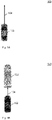
Fig. 7 shows anillustration 700 of an example of a road rasterization of a highway according to various embodiments. Avehicle 702 is shown on ahighway 704. Properties of a left boundary may be provided in a first row of the multi-channel image like data structure 706, like illustrated byarrow 708. Properties of a first lane marking may be provided in a second row of the multi-channel image like data structure 706, like illustrated byarrow 710. Properties of a second lane marking may be provided in a third row of the multi-channel image like data structure 706, like illustrated byarrow 712. Properties of a right boundary may be provided in a fourth row of the multi-channel image like data structure 706, like illustrated byarrow 714. - For example, the road opens a further lane on the right, meaning that the x coordinate of the right boundary increases, like illustrated in the last row of the multi-channel image like data structure 706.
- For an autonomously driving vehicle, the following highway lateral movements may be available: keep lane, lane change to the left, and lane change to the right. Depending on target in-lane position, modeling three lanes with four lane markings (for example a left boundary, a first lane marking, a second lane marking, and a right lane marking) may be sufficient for highway application, including target lane, adjacent left and right lanes.
- As illustrated in
Fig. 7 , a lane split may mean that before the split the data is filled with 0, including its validness feature, and afterwards, non-zero values (x5, x6, x7, x8, x9, ...) are provided. -
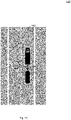
Fig. 8 shows anillustration 800 of an example of a road rasterization of a highway according to various embodiments. Avehicle 802 is shown on ahighway 804. Properties of a left boundary may be provided in a second row of the multi-channel image likedata structure 806, like illustrated byarrow 808. Properties of a middle lane marking may be provided in a third row of the multi-channel image likedata structure 806, like illustrated byarrow 810. Properties of a right boundary may be provided in a fourth row of the multi-channel image likedata structure 806, like illustrated byarrow 812. - It will be understood that even though only three lane markings are present, in order to make it possible to capture the road scenario illustrated in
Fig. 7 , four rows may be provided in the multi-channel image likedata structure 806 ofFig. 8 . In other words, the non-existing lane marking can be filled with 0 values. - For the lane merging scenario, the merged lane markings can be filled with 0 values (as for example illustrated in the second row of the multi-channel image like
data structure 806 inFig. 8 ). -
Fig. 9 shows a flow diagram 900 illustrating a method for determining an attribute of an object at a pre-determined point according to various embodiments. At 902, data representing a plurality of properties of a plurality of items of a vicinity of the object at a plurality of points along a trajectory of the object may be determined. At 904, the data may be arranged in a multi-channel image-like data structure, the multi-channel image-like data structure having a plurality of columns, a plurality of rows, and a plurality of channels, wherein the data is arranged in the image-like data structure, so that each of one of the rows or the columns or the channels of the image-like data structure corresponds to one of the plurality of properties of one of the plurality of items at the plurality of points, and each of one other of the rows or the columns or the channels of the image-like data structure corresponds to one the plurality of properties of the plurality of items at one of the plurality of points, and each of yet one other of the rows or the columns or the channels of the image-like data structure corresponds to the plurality of properties of one of the plurality of items at one of the plurality of points. At 906, the attribute of the object may be determined at the pre-determined point using a pre-determined rule based on the image-like data structure. - According to various embodiments, the object may be a vehicle.
- According to various embodiments, the items may include or may be lane markings, road boundaries, guard rails, or barriers.
- According to various embodiments, the plurality of points may include or may be past time points, and wherein the pre-determined point is a time point succeeding the plurality of time points; or the plurality of points may include or may be future time points, and wherein the pre-determined point is a time point preceding the plurality of time points.
- According to various embodiments, the plurality of points may include or may be past spatial points along a past trajectory of the object, and wherein the pre-determined point is a location succeeding the plurality of past spatial points; or the plurality of points may include or may be future spatial points along a future trajectory of the object, and wherein the pre-determined point is a location preceding the plurality of future spatial points.
- According to various embodiments, the property may include or may be at least one of an x position, a y position points, a validness flag, a lane marking type flag, or a color flag.
- According to various embodiments, the pre-determined rule may take image data as input data.
- According to various embodiments, the pre-determined rule may include or may be a neural network.
- According to various embodiments, the computer implemented method may further include the following step carried out by the computer hardware components: assigning a pre-determined value to an entry of the image-like data structure if a property is not available for the object and the point corresponding to the entry.
- According to various embodiments, the computer implemented method may further include the following step carried out by the computer hardware components: estimating a potential risk of collision based on the determined attribute; and/or determining a trajectory of the object to be followed for autonomous motion of the object based on the determined attribute; and/ or determining a maneuver to be executed based on the determined attribute.
- According to various embodiments, the maneuver to be executed may include or may be at least one of: accelerating, braking, steering, changing lane to the left, changing lane to the right, outputting a warning indication, switching on hazard warning lights, or activating a horn.
- Each of the
steps -
Fig. 10 shows anattribute determination system 1000 according to various embodiments. Theattribute determination system 1000 may include adata determination circuit 1002, an arrangingcircuit 1004, and anattribute determination circuit 1006. - The
data determination circuit 1002 may be configured to determine data representing a plurality of properties of a plurality of items of a vicinity of an object at a plurality of points along a trajectory of the object. - The arranging
circuit 1004 may be configured to arrange the data in a multi-channel image-like data structure, the multi-channel image-like data structure having a plurality of columns, a plurality of rows, and a plurality of channels, wherein the data is arranged in the image-like data structure, so that each of one of the rows or the columns or the channels of the image-like data structure corresponds to one of the plurality of properties of one of the plurality of items at the plurality of points, and each of one other of the rows or the columns or the channels of the image-like data structure corresponds to one the plurality of properties of the plurality of items at one of the plurality of points, and each of yet one other of the rows or the columns or the channels of the image-like data structure corresponds to the plurality of properties of one of the plurality of items at one of the plurality of points. - The
attribute determination circuit 1006 may be configured to determine the attribute of the object at a pre-determined point using a pre-determined rule based on the image-like data structure. - The
data determination circuit 1002, the arrangingcircuit 1004, and theattribute determination circuit 1006 may be coupled with each other, e.g. via anelectrical connection 1008, such as e.g. a cable or a computer bus or via any other suitable electrical connection to exchange electrical signals. - A "circuit" may be understood as any kind of a logic implementing entity, which may be special purpose circuitry or a processor executing a program stored in a memory, firmware, or any combination thereof.
-
Fig. 11 shows acomputer system 1100 with a plurality of computer hardware components configured to carry out steps of a computer implemented method for determining an attribute of an object at a pre-determined point according to various embodiments. Thecomputer system 1100 may include aprocessor 1102, amemory 1104, and anon-transitory data storage 1106. - The
processor 1102 may carry out instructions provided in thememory 1104. Thenon-transitory data storage 1106 may store a computer program, including the instructions that may be transferred to thememory 1104 and then executed by theprocessor 1102. - The
processor 1102, thememory 1104, and thenon-transitory data storage 1106 may be coupled with each other, e.g. via anelectrical connection 1108, such as e.g. a cable or a computer bus or via any other suitable electrical connection to exchange electrical signals. - The terms "coupling" or "connection" are intended to include a direct "coupling" (for example via a physical link) or direct "connection" as well as an indirect "coupling" or indirect "connection" (for example via a logical link), respectively.
- It will be understood that what has been described for one of the methods above may analogously hold true for the
attribute determination system 1000 and/or for thecomputer system 1100. -
- 100
- illustration of a vehicle
- 102
- vehicle
- 104
- arrow
- 120
- illustration of the vehicle
- 122
- further vehicle
- 140
- illustration of the vehicle
- 142
- road
- 144
- arrow
- 200
- illustration of a convolutional neural network
- 202
- source layer
- 204
- convolutional kernel
- 206
- destination layer
- 300
- illustration of lane marking rasterization according to various embodiments
- 302
- vehicle
- 304
- lane marking
- 306
- rasterization
- 308
- one row multi-channel image
- 400
- illustration of how to rasterize a whole road structure according to various embodiments
- 402
- image
- 404
- barrier
- 406
- static-context image
- 500
- illustration of how to represent the complete driving scene according to various embodiments
- 502
- scenario
- 504
- vehicle's past trajectory
- 506
- trajectory encoder
- 508
- latent code
- 510
- reshape operation
- 512
- multiple channels
- 514
- concatenation
- 516
- 2D multi-channel image
- 600
- illustration of an application of the 2D image-like data structure for trajectory prediction according to various embodiments
- 602
- deep neural network
- 604
- predicted future trajectory
- 700
- illustration of an example of a road rasterization of a highway according to various embodiments
- 702
- vehicle
- 704
- highway
- 706
- multi-channel image like data structure
- 708
- arrow
- 710
- arrow
- 712
- arrow
- 714
- arrow
- 800
- illustration of an example of a road rasterization of a highway according to various embodiments
- 802
- vehicle
- 804
- highway
- 806
- multi-channel image like data structure
- 808
- arrow
- 810
- arrow
- 812
- arrow
- 900
- flow diagram illustrating a method for determining an attribute of an object at a pre-determined point according to various embodiments
- 902
- step of determining data representing a plurality of properties of a plurality of items of a vicinity of the object at a plurality of points along a trajectory of the object
- 904
- step of arranging the data in a multi-channel image-like data structure, the multi-channel image-like data structure having a plurality of columns, a plurality of rows, and a plurality of channels, wherein the data is arranged in the image-like data structure
- 906
- step of determining the attribute of the object at the pre-determined point using a pre-determined rule based on the image-like data structure
- 1000
- attribute determination system
- 1002
- data determination circuit
- 1004
- arranging circuit
- 1006
- attribute determination circuit
- 1008
- connection
- 1100
- computer system according to various embodiments
- 1102
- processor
- 1104
- memory
- 1106
- non-transitory data storage
- 1108
- connection
Claims (15)
- Computer implemented method for determining an attribute of an object at a pre-determined point,
the method comprising the following steps carried out by computer hardware components:- determining (902) data representing a plurality of properties of a plurality of items of a vicinity of the object at a plurality of points along a trajectory of the object;- arranging (904) the data in a multi-channel image-like data structure, the multi-channel image-like data structure having a plurality of columns, a plurality of rows, and a plurality of channels, wherein the data is arranged in the image-like data structure, so that each of one of the rows or the columns or the channels of the image-like data structure corresponds to one of the plurality of properties of one of the plurality of items at the plurality of points, and
each of one other of the rows or the columns or the channels of the image-like data structure corresponds to one the plurality of properties of the plurality of items at one of the plurality of points, and each of yet one other of the rows or the columns or the channels of the image-like data structure corresponds to the plurality of properties of one of the plurality of items at one of the plurality of points; and- determining (906) the attribute of the object at the pre-determined point using a pre-determined rule based on the image-like data structure. - The computer implemented method of claim 1,
wherein the object is a vehicle. - The computer implemented method of at least one of claims 1 or 2,
wherein the items comprise lane markings, road boundaries, guard rails, or barriers. - The computer implemented method of at least one of claims 1 to 3,
wherein the plurality of points comprise past time points, and wherein the pre-determined point is a time point succeeding the plurality of time points; or
wherein the plurality of points comprise future time points, and wherein the pre-determined point is a time point preceding the plurality of time points. - The computer implemented method of at least one of claims 1 to 4,
wherein the plurality of points comprise past spatial points along a past trajectory of the object, and wherein the pre-determined point is a location succeeding the plurality of past spatial points;
or
wherein the plurality of points comprise future spatial points along a future trajectory of the object, and wherein the pre-determined point is a location preceding the plurality of future spatial points. - The computer implemented method of at least one of claims 1 to 5,
wherein the property comprises at least one of an x position, a y position points, a validness flag, a lane marking type flag, or a color flag. - The computer implemented method of at least one of claims 1 to 6, wherein the pre-determined rule takes image data as input data.
- The computer implemented method of at least one of claims 1 to 7,
wherein the pre-determined rule comprises a neural network. - The computer implemented method of at least one of claims 1 to 8, further comprising the following step carried out by the computer hardware components:
assigning a pre-determined value to an entry of the image-like data structure if a property is not available for the object and the point corresponding to the entry. - The computer implemented method of at least one of claims 1 to 9, further comprising the following step carried out by the computer hardware components:estimating a potential risk of collision based on the determined attribute; and/ordetermining a trajectory of the object to be followed for autonomous motion of the object based on the determined attribute; and/ or.determining a maneuver to be executed based on the determined attribute.
- The computer implemented method of claim 10,
wherein the maneuver to be executed comprises at least one of:
accelerating, braking, steering, changing lane to the left, changing lane to the right, outputting a warning indication, switching on hazard warning lights, or activating a horn. - Computer system (1100), the computer system (1100) comprising a plurality of computer hardware components configured to carry out steps of the computer implemented method of at least one of claims 1 to 11.
- Vehicle comprising the computer system (1100) of claim 12.
- The vehicle of claim 13, further comprising:a sensor configured to determine sensor data;wherein the properties are determined based on the sensor data.
- Non-transitory computer readable medium comprising instructions for carrying out the computer implemented method of at least one of claims 1 to 11.
Priority Applications (1)
| Application Number | Priority Date | Filing Date | Title |
|---|---|---|---|
| EP20205090.2A EP3992942B1 (en) | 2020-11-02 | 2020-11-02 | Methods and systems for determining an attribute of an object at a pre-determined point |
Applications Claiming Priority (1)
| Application Number | Priority Date | Filing Date | Title |
|---|---|---|---|
| EP20205090.2A EP3992942B1 (en) | 2020-11-02 | 2020-11-02 | Methods and systems for determining an attribute of an object at a pre-determined point |
Publications (2)
| Publication Number | Publication Date |
|---|---|
| EP3992942A1 true EP3992942A1 (en) | 2022-05-04 |
| EP3992942B1 EP3992942B1 (en) | 2024-03-13 |
Family
ID=73043144
Family Applications (1)
| Application Number | Title | Priority Date | Filing Date |
|---|---|---|---|
| EP20205090.2A Active EP3992942B1 (en) | 2020-11-02 | 2020-11-02 | Methods and systems for determining an attribute of an object at a pre-determined point |
Country Status (1)
| Country | Link |
|---|---|
| EP (1) | EP3992942B1 (en) |
Citations (4)
| Publication number | Priority date | Publication date | Assignee | Title |
|---|---|---|---|---|
| US20190049987A1 (en) * | 2017-08-08 | 2019-02-14 | Uber Technologies, Inc. | Object Motion Prediction and Autonomous Vehicle Control |
| US20190147255A1 (en) * | 2017-11-15 | 2019-05-16 | Uber Technologies, Inc. | Systems and Methods for Generating Sparse Geographic Data for Autonomous Vehicles |
| US20190179328A1 (en) * | 2017-12-11 | 2019-06-13 | Volvo Car Corporation | Path prediction for a vehicle |
| US20190361454A1 (en) * | 2018-05-24 | 2019-11-28 | GM Global Technology Operations LLC | Control systems, control methods and controllers for an autonomous vehicle |
-
2020
- 2020-11-02 EP EP20205090.2A patent/EP3992942B1/en active Active
Patent Citations (4)
| Publication number | Priority date | Publication date | Assignee | Title |
|---|---|---|---|---|
| US20190049987A1 (en) * | 2017-08-08 | 2019-02-14 | Uber Technologies, Inc. | Object Motion Prediction and Autonomous Vehicle Control |
| US20190147255A1 (en) * | 2017-11-15 | 2019-05-16 | Uber Technologies, Inc. | Systems and Methods for Generating Sparse Geographic Data for Autonomous Vehicles |
| US20190179328A1 (en) * | 2017-12-11 | 2019-06-13 | Volvo Car Corporation | Path prediction for a vehicle |
| US20190361454A1 (en) * | 2018-05-24 | 2019-11-28 | GM Global Technology Operations LLC | Control systems, control methods and controllers for an autonomous vehicle |
Also Published As
| Publication number | Publication date |
|---|---|
| EP3992942B1 (en) | 2024-03-13 |
Similar Documents
| Publication | Publication Date | Title |
|---|---|---|
| Niranjan et al. | Deep learning based object detection model for autonomous driving research using carla simulator | |
| CN110008978B (en) | Hazard classification training method, hazard classification method, assisted or automatic vehicle driving system | |
| US11288963B2 (en) | Autonomous vehicles featuring vehicle intention system | |
| EP4137845B1 (en) | Methods and systems for predicting properties of a plurality of objects in a vicinity of a vehicle | |
| JP6925796B2 (en) | Methods and systems, vehicles, and computer programs that assist the driver of the vehicle in driving the vehicle. | |
| CN112868022A (en) | Driving scenarios for autonomous vehicles | |
| US11676488B2 (en) | Method and system for determining an attribute of an object at a pre-determined time point | |
| EP4456016A1 (en) | Method for predicting trajectories of road users | |
| US20200130682A1 (en) | Safety system, automated driving system, and methods thereof | |
| CN116189135A (en) | Method for determining agent trajectories in multi-agent scenarios | |
| EP4736134A1 (en) | System and methods for providing driver assistance alerts using an end-to-end artificially intelligent collision avoidance system and advanced driver assistance systems | |
| Krüger et al. | Interaction-aware trajectory prediction based on a 3D spatio-temporal tensor representation using convolutional–recurrent neural networks | |
| Aboah et al. | Ai-based framework for understanding car following behaviors of drivers in a naturalistic driving environment | |
| EP4224434A1 (en) | Apparatus and method for evaluating a machine learning model used for assisted or autonomous driving of a vehicle | |
| US20250206343A1 (en) | Method For Determining Control Parameters For Driving A Vehicle | |
| EP3992942B1 (en) | Methods and systems for determining an attribute of an object at a pre-determined point | |
| EP4456015B1 (en) | Method for predicting trajectories of road users | |
| US12110035B2 (en) | Map based annotation for autonomous movement models training | |
| KR102602271B1 (en) | Method and apparatus for determining the possibility of collision of a driving vehicle using an artificial neural network | |
| EP4001041B1 (en) | Method and system for determining a maneuver to be executed by an autonomous vehicle | |
| JP2023039926A (en) | Perceptual Field-Based Driving-Related Manipulation | |
| Pankiewicz et al. | Promises and challenges of reinforcement learning applications in motion planning of automated vehicles | |
| JP7829409B2 (en) | Information processing device, information processing method, and learning device | |
| US20230365155A1 (en) | Virtual fields driving related operations | |
| EP4700717A1 (en) | Machine learning models for processing vehicle sensor data |
Legal Events
| Date | Code | Title | Description |
|---|---|---|---|
| PUAI | Public reference made under article 153(3) epc to a published international application that has entered the european phase |
Free format text: ORIGINAL CODE: 0009012 |
|
| STAA | Information on the status of an ep patent application or granted ep patent |
Free format text: STATUS: THE APPLICATION HAS BEEN PUBLISHED |
|
| AK | Designated contracting states |
Kind code of ref document: A1 Designated state(s): AL AT BE BG CH CY CZ DE DK EE ES FI FR GB GR HR HU IE IS IT LI LT LU LV MC MK MT NL NO PL PT RO RS SE SI SK SM TR |
|
| STAA | Information on the status of an ep patent application or granted ep patent |
Free format text: STATUS: REQUEST FOR EXAMINATION WAS MADE |
|
| 17P | Request for examination filed |
Effective date: 20221103 |
|
| RBV | Designated contracting states (corrected) |
Designated state(s): AL AT BE BG CH CY CZ DE DK EE ES FI FR GB GR HR HU IE IS IT LI LT LU LV MC MK MT NL NO PL PT RO RS SE SI SK SM TR |
|
| RAP3 | Party data changed (applicant data changed or rights of an application transferred) |
Owner name: APTIV TECHNOLOGIES LIMITED |
|
| GRAP | Despatch of communication of intention to grant a patent |
Free format text: ORIGINAL CODE: EPIDOSNIGR1 |
|
| RIC1 | Information provided on ipc code assigned before grant |
Ipc: G06V 20/56 20220101ALI20230922BHEP Ipc: G06V 10/764 20220101ALI20230922BHEP Ipc: G06T 7/246 20170101ALI20230922BHEP Ipc: G08G 1/16 20060101AFI20230922BHEP |
|
| STAA | Information on the status of an ep patent application or granted ep patent |
Free format text: STATUS: GRANT OF PATENT IS INTENDED |
|
| INTG | Intention to grant announced |
Effective date: 20231102 |
|
| P01 | Opt-out of the competence of the unified patent court (upc) registered |
Effective date: 20231219 |
|
| GRAS | Grant fee paid |
Free format text: ORIGINAL CODE: EPIDOSNIGR3 |
|
| GRAA | (expected) grant |
Free format text: ORIGINAL CODE: 0009210 |
|
| STAA | Information on the status of an ep patent application or granted ep patent |
Free format text: STATUS: THE PATENT HAS BEEN GRANTED |
|
| AK | Designated contracting states |
Kind code of ref document: B1 Designated state(s): AL AT BE BG CH CY CZ DE DK EE ES FI FR GB GR HR HU IE IS IT LI LT LU LV MC MK MT NL NO PL PT RO RS SE SI SK SM TR |
|
| REG | Reference to a national code |
Ref country code: GB Ref legal event code: FG4D |
|
| REG | Reference to a national code |
Ref country code: CH Ref legal event code: EP |
|
| REG | Reference to a national code |
Ref country code: DE Ref legal event code: R096 Ref document number: 602020027100 Country of ref document: DE |
|
| REG | Reference to a national code |
Ref country code: IE Ref legal event code: FG4D |
|
| PG25 | Lapsed in a contracting state [announced via postgrant information from national office to epo] |
Ref country code: LT Free format text: LAPSE BECAUSE OF FAILURE TO SUBMIT A TRANSLATION OF THE DESCRIPTION OR TO PAY THE FEE WITHIN THE PRESCRIBED TIME-LIMIT Effective date: 20240313 |
|
| REG | Reference to a national code |
Ref country code: LT Ref legal event code: MG9D |
|
| PG25 | Lapsed in a contracting state [announced via postgrant information from national office to epo] |
Ref country code: GR Free format text: LAPSE BECAUSE OF FAILURE TO SUBMIT A TRANSLATION OF THE DESCRIPTION OR TO PAY THE FEE WITHIN THE PRESCRIBED TIME-LIMIT Effective date: 20240614 |
|
| REG | Reference to a national code |
Ref country code: NL Ref legal event code: MP Effective date: 20240313 |
|
| PG25 | Lapsed in a contracting state [announced via postgrant information from national office to epo] |
Ref country code: RS Free format text: LAPSE BECAUSE OF FAILURE TO SUBMIT A TRANSLATION OF THE DESCRIPTION OR TO PAY THE FEE WITHIN THE PRESCRIBED TIME-LIMIT Effective date: 20240613 Ref country code: HR Free format text: LAPSE BECAUSE OF FAILURE TO SUBMIT A TRANSLATION OF THE DESCRIPTION OR TO PAY THE FEE WITHIN THE PRESCRIBED TIME-LIMIT Effective date: 20240313 |
|
| PG25 | Lapsed in a contracting state [announced via postgrant information from national office to epo] |
Ref country code: ES Free format text: LAPSE BECAUSE OF FAILURE TO SUBMIT A TRANSLATION OF THE DESCRIPTION OR TO PAY THE FEE WITHIN THE PRESCRIBED TIME-LIMIT Effective date: 20240313 |
|
| PG25 | Lapsed in a contracting state [announced via postgrant information from national office to epo] |
Ref country code: RS Free format text: LAPSE BECAUSE OF FAILURE TO SUBMIT A TRANSLATION OF THE DESCRIPTION OR TO PAY THE FEE WITHIN THE PRESCRIBED TIME-LIMIT Effective date: 20240613 Ref country code: NO Free format text: LAPSE BECAUSE OF FAILURE TO SUBMIT A TRANSLATION OF THE DESCRIPTION OR TO PAY THE FEE WITHIN THE PRESCRIBED TIME-LIMIT Effective date: 20240613 Ref country code: LT Free format text: LAPSE BECAUSE OF FAILURE TO SUBMIT A TRANSLATION OF THE DESCRIPTION OR TO PAY THE FEE WITHIN THE PRESCRIBED TIME-LIMIT Effective date: 20240313 Ref country code: HR Free format text: LAPSE BECAUSE OF FAILURE TO SUBMIT A TRANSLATION OF THE DESCRIPTION OR TO PAY THE FEE WITHIN THE PRESCRIBED TIME-LIMIT Effective date: 20240313 Ref country code: GR Free format text: LAPSE BECAUSE OF FAILURE TO SUBMIT A TRANSLATION OF THE DESCRIPTION OR TO PAY THE FEE WITHIN THE PRESCRIBED TIME-LIMIT Effective date: 20240614 Ref country code: FI Free format text: LAPSE BECAUSE OF FAILURE TO SUBMIT A TRANSLATION OF THE DESCRIPTION OR TO PAY THE FEE WITHIN THE PRESCRIBED TIME-LIMIT Effective date: 20240313 Ref country code: ES Free format text: LAPSE BECAUSE OF FAILURE TO SUBMIT A TRANSLATION OF THE DESCRIPTION OR TO PAY THE FEE WITHIN THE PRESCRIBED TIME-LIMIT Effective date: 20240313 Ref country code: BG Free format text: LAPSE BECAUSE OF FAILURE TO SUBMIT A TRANSLATION OF THE DESCRIPTION OR TO PAY THE FEE WITHIN THE PRESCRIBED TIME-LIMIT Effective date: 20240313 |
|
| REG | Reference to a national code |
Ref country code: AT Ref legal event code: MK05 Ref document number: 1666516 Country of ref document: AT Kind code of ref document: T Effective date: 20240313 |
|
| PG25 | Lapsed in a contracting state [announced via postgrant information from national office to epo] |
Ref country code: SE Free format text: LAPSE BECAUSE OF FAILURE TO SUBMIT A TRANSLATION OF THE DESCRIPTION OR TO PAY THE FEE WITHIN THE PRESCRIBED TIME-LIMIT Effective date: 20240313 Ref country code: LV Free format text: LAPSE BECAUSE OF FAILURE TO SUBMIT A TRANSLATION OF THE DESCRIPTION OR TO PAY THE FEE WITHIN THE PRESCRIBED TIME-LIMIT Effective date: 20240313 |
|
| PG25 | Lapsed in a contracting state [announced via postgrant information from national office to epo] |
Ref country code: NL Free format text: LAPSE BECAUSE OF FAILURE TO SUBMIT A TRANSLATION OF THE DESCRIPTION OR TO PAY THE FEE WITHIN THE PRESCRIBED TIME-LIMIT Effective date: 20240313 |
|
| PG25 | Lapsed in a contracting state [announced via postgrant information from national office to epo] |
Ref country code: NL Free format text: LAPSE BECAUSE OF FAILURE TO SUBMIT A TRANSLATION OF THE DESCRIPTION OR TO PAY THE FEE WITHIN THE PRESCRIBED TIME-LIMIT Effective date: 20240313 |
|
| PG25 | Lapsed in a contracting state [announced via postgrant information from national office to epo] |
Ref country code: IS Free format text: LAPSE BECAUSE OF FAILURE TO SUBMIT A TRANSLATION OF THE DESCRIPTION OR TO PAY THE FEE WITHIN THE PRESCRIBED TIME-LIMIT Effective date: 20240713 |
|
| PG25 | Lapsed in a contracting state [announced via postgrant information from national office to epo] |
Ref country code: SM Free format text: LAPSE BECAUSE OF FAILURE TO SUBMIT A TRANSLATION OF THE DESCRIPTION OR TO PAY THE FEE WITHIN THE PRESCRIBED TIME-LIMIT Effective date: 20240313 Ref country code: PT Free format text: LAPSE BECAUSE OF FAILURE TO SUBMIT A TRANSLATION OF THE DESCRIPTION OR TO PAY THE FEE WITHIN THE PRESCRIBED TIME-LIMIT Effective date: 20240715 |
|
| PG25 | Lapsed in a contracting state [announced via postgrant information from national office to epo] |
Ref country code: CZ Free format text: LAPSE BECAUSE OF FAILURE TO SUBMIT A TRANSLATION OF THE DESCRIPTION OR TO PAY THE FEE WITHIN THE PRESCRIBED TIME-LIMIT Effective date: 20240313 Ref country code: EE Free format text: LAPSE BECAUSE OF FAILURE TO SUBMIT A TRANSLATION OF THE DESCRIPTION OR TO PAY THE FEE WITHIN THE PRESCRIBED TIME-LIMIT Effective date: 20240313 |
|
| PG25 | Lapsed in a contracting state [announced via postgrant information from national office to epo] |
Ref country code: AT Free format text: LAPSE BECAUSE OF FAILURE TO SUBMIT A TRANSLATION OF THE DESCRIPTION OR TO PAY THE FEE WITHIN THE PRESCRIBED TIME-LIMIT Effective date: 20240313 |
|
| PG25 | Lapsed in a contracting state [announced via postgrant information from national office to epo] |
Ref country code: PL Free format text: LAPSE BECAUSE OF FAILURE TO SUBMIT A TRANSLATION OF THE DESCRIPTION OR TO PAY THE FEE WITHIN THE PRESCRIBED TIME-LIMIT Effective date: 20240313 |
|
| PG25 | Lapsed in a contracting state [announced via postgrant information from national office to epo] |
Ref country code: SK Free format text: LAPSE BECAUSE OF FAILURE TO SUBMIT A TRANSLATION OF THE DESCRIPTION OR TO PAY THE FEE WITHIN THE PRESCRIBED TIME-LIMIT Effective date: 20240313 |
|
| PG25 | Lapsed in a contracting state [announced via postgrant information from national office to epo] |
Ref country code: SM Free format text: LAPSE BECAUSE OF FAILURE TO SUBMIT A TRANSLATION OF THE DESCRIPTION OR TO PAY THE FEE WITHIN THE PRESCRIBED TIME-LIMIT Effective date: 20240313 Ref country code: SK Free format text: LAPSE BECAUSE OF FAILURE TO SUBMIT A TRANSLATION OF THE DESCRIPTION OR TO PAY THE FEE WITHIN THE PRESCRIBED TIME-LIMIT Effective date: 20240313 Ref country code: RO Free format text: LAPSE BECAUSE OF FAILURE TO SUBMIT A TRANSLATION OF THE DESCRIPTION OR TO PAY THE FEE WITHIN THE PRESCRIBED TIME-LIMIT Effective date: 20240313 Ref country code: PT Free format text: LAPSE BECAUSE OF FAILURE TO SUBMIT A TRANSLATION OF THE DESCRIPTION OR TO PAY THE FEE WITHIN THE PRESCRIBED TIME-LIMIT Effective date: 20240715 Ref country code: PL Free format text: LAPSE BECAUSE OF FAILURE TO SUBMIT A TRANSLATION OF THE DESCRIPTION OR TO PAY THE FEE WITHIN THE PRESCRIBED TIME-LIMIT Effective date: 20240313 Ref country code: IS Free format text: LAPSE BECAUSE OF FAILURE TO SUBMIT A TRANSLATION OF THE DESCRIPTION OR TO PAY THE FEE WITHIN THE PRESCRIBED TIME-LIMIT Effective date: 20240713 Ref country code: EE Free format text: LAPSE BECAUSE OF FAILURE TO SUBMIT A TRANSLATION OF THE DESCRIPTION OR TO PAY THE FEE WITHIN THE PRESCRIBED TIME-LIMIT Effective date: 20240313 Ref country code: CZ Free format text: LAPSE BECAUSE OF FAILURE TO SUBMIT A TRANSLATION OF THE DESCRIPTION OR TO PAY THE FEE WITHIN THE PRESCRIBED TIME-LIMIT Effective date: 20240313 Ref country code: AT Free format text: LAPSE BECAUSE OF FAILURE TO SUBMIT A TRANSLATION OF THE DESCRIPTION OR TO PAY THE FEE WITHIN THE PRESCRIBED TIME-LIMIT Effective date: 20240313 |
|
| PG25 | Lapsed in a contracting state [announced via postgrant information from national office to epo] |
Ref country code: IT Free format text: LAPSE BECAUSE OF FAILURE TO SUBMIT A TRANSLATION OF THE DESCRIPTION OR TO PAY THE FEE WITHIN THE PRESCRIBED TIME-LIMIT Effective date: 20240313 |
|
| REG | Reference to a national code |
Ref country code: DE Ref legal event code: R097 Ref document number: 602020027100 Country of ref document: DE |
|
| PG25 | Lapsed in a contracting state [announced via postgrant information from national office to epo] |
Ref country code: IT Free format text: LAPSE BECAUSE OF FAILURE TO SUBMIT A TRANSLATION OF THE DESCRIPTION OR TO PAY THE FEE WITHIN THE PRESCRIBED TIME-LIMIT Effective date: 20240313 |
|
| PG25 | Lapsed in a contracting state [announced via postgrant information from national office to epo] |
Ref country code: DK Free format text: LAPSE BECAUSE OF FAILURE TO SUBMIT A TRANSLATION OF THE DESCRIPTION OR TO PAY THE FEE WITHIN THE PRESCRIBED TIME-LIMIT Effective date: 20240313 |
|
| PLBE | No opposition filed within time limit |
Free format text: ORIGINAL CODE: 0009261 |
|
| STAA | Information on the status of an ep patent application or granted ep patent |
Free format text: STATUS: NO OPPOSITION FILED WITHIN TIME LIMIT |
|
| PG25 | Lapsed in a contracting state [announced via postgrant information from national office to epo] |
Ref country code: DK Free format text: LAPSE BECAUSE OF FAILURE TO SUBMIT A TRANSLATION OF THE DESCRIPTION OR TO PAY THE FEE WITHIN THE PRESCRIBED TIME-LIMIT Effective date: 20240313 |
|
| 26N | No opposition filed |
Effective date: 20241216 |
|
| PG25 | Lapsed in a contracting state [announced via postgrant information from national office to epo] |
Ref country code: SI Free format text: LAPSE BECAUSE OF FAILURE TO SUBMIT A TRANSLATION OF THE DESCRIPTION OR TO PAY THE FEE WITHIN THE PRESCRIBED TIME-LIMIT Effective date: 20240313 |
|
| REG | Reference to a national code |
Ref country code: DE Ref legal event code: R081 Ref document number: 602020027100 Country of ref document: DE Owner name: APTIV TECHNOLOGIES AG, CH Free format text: FORMER OWNER: APTIV TECHNOLOGIES LIMITED, ST. MICHAEL, BB |
|
| REG | Reference to a national code |
Ref country code: CH Ref legal event code: PL |
|
| PG25 | Lapsed in a contracting state [announced via postgrant information from national office to epo] |
Ref country code: MC Free format text: LAPSE BECAUSE OF FAILURE TO SUBMIT A TRANSLATION OF THE DESCRIPTION OR TO PAY THE FEE WITHIN THE PRESCRIBED TIME-LIMIT Effective date: 20240313 |
|
| PG25 | Lapsed in a contracting state [announced via postgrant information from national office to epo] |
Ref country code: LU Free format text: LAPSE BECAUSE OF NON-PAYMENT OF DUE FEES Effective date: 20241102 |
|
| REG | Reference to a national code |
Ref country code: CH Ref legal event code: PL |
|
| PG25 | Lapsed in a contracting state [announced via postgrant information from national office to epo] |
Ref country code: CH Free format text: LAPSE BECAUSE OF NON-PAYMENT OF DUE FEES Effective date: 20241130 |
|
| REG | Reference to a national code |
Ref country code: BE Ref legal event code: MM Effective date: 20241130 |
|
| PG25 | Lapsed in a contracting state [announced via postgrant information from national office to epo] |
Ref country code: BE Free format text: LAPSE BECAUSE OF NON-PAYMENT OF DUE FEES Effective date: 20241130 |
|
| PG25 | Lapsed in a contracting state [announced via postgrant information from national office to epo] |
Ref country code: IE Free format text: LAPSE BECAUSE OF NON-PAYMENT OF DUE FEES Effective date: 20241102 |
|
| PGFP | Annual fee paid to national office [announced via postgrant information from national office to epo] |
Ref country code: DE Payment date: 20251010 Year of fee payment: 6 |
|
| PGFP | Annual fee paid to national office [announced via postgrant information from national office to epo] |
Ref country code: GB Payment date: 20251015 Year of fee payment: 6 |
|
| PGFP | Annual fee paid to national office [announced via postgrant information from national office to epo] |
Ref country code: FR Payment date: 20251014 Year of fee payment: 6 |
|
| PG25 | Lapsed in a contracting state [announced via postgrant information from national office to epo] |
Ref country code: HU Free format text: LAPSE BECAUSE OF FAILURE TO SUBMIT A TRANSLATION OF THE DESCRIPTION OR TO PAY THE FEE WITHIN THE PRESCRIBED TIME-LIMIT; INVALID AB INITIO Effective date: 20201102 |
|
| PG25 | Lapsed in a contracting state [announced via postgrant information from national office to epo] |
Ref country code: CY Free format text: LAPSE BECAUSE OF FAILURE TO SUBMIT A TRANSLATION OF THE DESCRIPTION OR TO PAY THE FEE WITHIN THE PRESCRIBED TIME-LIMIT; INVALID AB INITIO Effective date: 20201102 |