EP3992831A1 - Method, system and software for assessing component failure probability in a vehicle e/e architecture - Google Patents
Method, system and software for assessing component failure probability in a vehicle e/e architecture Download PDFInfo
- Publication number
- EP3992831A1 EP3992831A1 EP20204322.0A EP20204322A EP3992831A1 EP 3992831 A1 EP3992831 A1 EP 3992831A1 EP 20204322 A EP20204322 A EP 20204322A EP 3992831 A1 EP3992831 A1 EP 3992831A1
- Authority
- EP
- European Patent Office
- Prior art keywords
- component
- data
- starting
- current path
- intervening
- Prior art date
- Legal status (The legal status is an assumption and is not a legal conclusion. Google has not performed a legal analysis and makes no representation as to the accuracy of the status listed.)
- Withdrawn
Links
Images


Classifications
-
- G—PHYSICS
- G06—COMPUTING OR CALCULATING; COUNTING
- G06F—ELECTRIC DIGITAL DATA PROCESSING
- G06F30/00—Computer-aided design [CAD]
- G06F30/10—Geometric CAD
- G06F30/15—Vehicle, aircraft or watercraft design
-
- G—PHYSICS
- G01—MEASURING; TESTING
- G01R—MEASURING ELECTRIC VARIABLES; MEASURING MAGNETIC VARIABLES
- G01R31/00—Arrangements for testing electric properties; Arrangements for locating electric faults; Arrangements for electrical testing characterised by what is being tested not provided for elsewhere
-
- G—PHYSICS
- G01—MEASURING; TESTING
- G01R—MEASURING ELECTRIC VARIABLES; MEASURING MAGNETIC VARIABLES
- G01R1/00—Details of instruments or arrangements of the types included in groups G01R5/00 - G01R13/00 and G01R31/00
- G01R1/02—General constructional details
- G01R1/04—Housings; Supporting members; Arrangements of terminals
-
- G—PHYSICS
- G06—COMPUTING OR CALCULATING; COUNTING
- G06F—ELECTRIC DIGITAL DATA PROCESSING
- G06F30/00—Computer-aided design [CAD]
- G06F30/30—Circuit design
- G06F30/39—Circuit design at the physical level
- G06F30/394—Routing
-
- G—PHYSICS
- G06—COMPUTING OR CALCULATING; COUNTING
- G06F—ELECTRIC DIGITAL DATA PROCESSING
- G06F2113/00—Details relating to the application field
- G06F2113/16—Cables, cable trees or wire harnesses
-
- G—PHYSICS
- G06—COMPUTING OR CALCULATING; COUNTING
- G06F—ELECTRIC DIGITAL DATA PROCESSING
- G06F2119/00—Details relating to the type or aim of the analysis or the optimisation
- G06F2119/02—Reliability analysis or reliability optimisation; Failure analysis, e.g. worst case scenario performance, failure mode and effects analysis [FMEA]
Definitions
- the present disclosure relates to a method and system of assessing component failure probability in a vehicle E/E architecture, and software for performing the same.
- E/E Electrical/Electronic
- software platforms such as PREEvision
- PREEvision are typically used for E/E development to provide a model-based development environment from system design through to the final wiring harness design.
- PREEvision is structured in several layers, thereby allowing teams of designers having different specialisms and competencies to work within their respective layer. For example, one design team may develop the circuit design at one level within PREEvision, with the topology and wiring harness design teams then subsequently designing their aspects on different levels above this.
- PREE vision provides a routing algorithm which calculates the shortest geometric path for segments between individual components based on the circuit topology design.
- the routing algorithm used for wiring harness design may not account for other factors.
- a potentially important issue relates to the power management of components.
- an autonomous driving controller is reliant on inputs from an array of peripheral components, such as radars, LIDARS, and cameras etc. Consequently, any power supply irregularities to any of the peripheral components could feasibly compromise the safe operation of the controller.
- the peripheral components would typically be distributed around the vehicle, and therefore will be connected through the wire harness. This is relevant because the power supply path for a particular peripheral component in a complex modern vehicle will also likely pass through hundreds of other components, wiring sections and terminals, depending not only on the wiring harness design, but also the circuit design and topology.
- the wiring harness designer has no awareness of the impact that their harness design choices may have on the power supply for particular components. Indeed, due to the complexity of modern E/E architectures, power supply issues may only be identified during manual testing.
- the present disclosure is therefore directed to addressing these issues.
- a method of assessing component failure probability in a vehicle E/E architecture including the steps of: A) receiving wiring data and component data for the vehicle E/E architecture; B) selecting a starting component in the E/E architecture; C) identifying one or more terminals of the starting component using the component data; D) identifying one or more wires connected to the one or more terminals using the wiring data; E) generating a first data record for a first current path starting with a first wire and conducting through one or more intervening components to an end point, wherein the current path through each intervening component is identified based on identifying an output terminal for the respective component using the component data; F) generating a first data log of the sequence of wires and intervening components along the first current path, starting with the selected component; G) recursively interrogating the wiring and component data for each intervening component along the first current path in reverse order and updating the first data record to include one or more alternate first current paths starting with the respective intervening component and conducting through one or more interven
- the failure probability of a particular selected component arising from features of its power distribution path may be accurately assessed.
- the output data allows relationships between intervening components and wiring in the power distribution path for a selected component to be identified across multiple levels within, for instance, a PREEvision environment. This may thereby allow failure and short-circuiting issues to be identified, and hence the development of safer E/E architectures to be facilitated.
- the method may be implemented on a computer system including a processor, a display, a user input device, and computer memory.
- the wiring data and component data may be stored in the computer memory.
- the starting component may be selected by a user using the user input device interacting with a user interface displayed on the display.
- the processor may execute software instructions for identifying the terminals and wires, generating the data records and data logs, and outputting an output data file by storing the data file in the computer memory.
- the computer memory may include different types of memory, such as RAM and storage drives. It will also be understood that the computer system may be a distributed system.
- the wiring and component data may be stored on computer memory in a server.
- processing may be performed by a processor at the server, with a user accessing the system from a workstation having the display and user input device.
- the wiring data includes at least one of: circuit data for providing information regarding the connections of components within circuits, and wiring harness data for providing information regarding the connections of components through the wiring harness.
- the component data includes specification data for providing information regarding the internal connections and terminals of the components.
- the method further includes the step of generating a fault tree based on the output data file.
- the fault tree may be generated as a graphical representation for analysis.
- the method further includes the step of generating a failure probability value for the starting component based on the sum of reference failure values for the intervening components in the one or more current paths of the starting component.
- step B of selecting a starting component includes a user selection.
- the method further includes the step of repeating steps A to J for a second or subsequent starting component.
- the power distribution path information for a number of components within a vehicle's E/E architecture may be identified.
- the end point is one of a ground and a power source.
- the end point is selected by a user. In this way, a user may investigate the power distribution path or paths between two selected components.
- a non-transitory computer readable medium storing software for assessing component failure probability in a vehicle E/E architecture and including instructions which, when executed by a processor, perform the steps of: A) receiving wiring data and component data for the vehicle E/E architecture; B) selecting a starting component in the E/E architecture; C) identifying one or more terminals of the starting component using the component data; D) identifying one or more wires connected to the one or more terminals using the wiring data; E) generating a first data record for a first current path starting with a first wire and conducting through one or more intervening components to an end point, wherein the current path through each intervening component is identified based on identifying an output terminal for the respective component using the component data; F) generating a first data log of the sequence of wires and intervening components along the first current path, starting with the selected component; G) recursively interrogating the wiring and component data for each intervening component along the first current path in reverse order and updating the first data record to include
- the non-transitory computer readable medium further includes instructions which, when executed by a processor, perform the step of generating a fault tree based on the output data file.
- the non-transitory computer readable medium further includes instructions which, when executed by a processor, perform the step of generating a failure probability value for the starting component based on the sum of reference failure values for the intervening components in the one or more current paths of the starting component.
- system for assessing component failure probability in a vehicle E/E architecture includes: an input block for receiving wiring data and component data for the vehicle E/E architecture, and for selecting a starting component in the E/E architecture; a calculation block for identifying one or more terminals of the starting component using the component data, and for identifying one or more wires connected to the one or more terminals using the wiring data, and for generating a first data record for a first current path starting with a first wire and conducting through one or more intervening components to an end point, wherein the current path through each intervening component is identified based on identifying an output terminal for the respective component using the component data; an output block for generating a first data log of the sequence of wires and intervening components along the first current path, starting with the selected component; and wherein the calculation block recursively interrogates the wiring and component data for each intervening component along the first current path in reverse order and updates the first data record to include one or more alternate first current paths starting with the respective intervening component
- system further includes a fault tree generator for generating a fault tree based on the output data file.
- system further includes a failure probability determination module for generating failure probability value for the starting component based on the sum of reference failure values for the intervening components in the one or more current paths of the starting component.
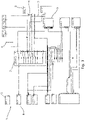
- FIG. 1 shows a simplified diagram of the components and power distribution paths within the power steering architecture 1.
- the components include, for example, electronic control units (ECU) 5, inliners 5, fuse relay boxes 3, generators 9, and actuators.
- ECU electronice control units
- Each component may include a plurality of terminals 6, and various components are connected to one another via the terminals 6 through wires 7. Switches within the components may connect different components with one another during different operating conditions.
- the power steering architecture 1 is developed in PREEvision and includes data representing the wiring 7 between components and specification data for the components themselves.
- the wiring data includes data representing both connections through the wiring harness and circuit board connections, albeit that these would be visualised in different layers within PREEvision. For example, whilst two components may appear adjacent in the circuit diagram, in reality they may be separated by meters of wiring harness and be routed through various terminal connectors and distribution blocks.
- the component data includes data representing the terminal connections for that component, as well as information regarding switchable connections between different terminals. That is, some components may have two terminals, which may be represented as an input and an output. However, other components may have three or more terminals, for instance to provide alternative outputs when in certain switching configurations. Again, aspects of this component information may be visualised in different layers within PREEvision.
- FIG. 2 shows a schematic block diagram of a software system 10 according to the illustrative embodiment.
- the system 10 is provided as a JAVA module plug-in for PREEvision.
- the system 10 includes an input block 11 which feeds inputs to a calculation block 12, which in turn generates output data through output block 13.
- the input block 11, calculation block 12, and output block 13 are executed by a processor of a computer system.
- the input block 11 may receive inputs from a user input device, such as a mouse, and display a user interface on a computer display for facilitating user selections.
- the input block 11, calculation block 12, and output block 13 may access computer memory for reading wiring and component data, as well as reading and writing record data and log data.
- the input block 14 includes a component selection section 14 for selecting a starting component.
- the component selection section 14 presents the user interface on the computer display within the PREEvision environment for a user to make selections and set parameters for the process.
- the user manually selects a starting component.
- the component selection section 14 may automatically select a starting component.
- the system 10 may select components in turn from a group of components fitting a particular classification, such as ECUs.
- the input block 14 further includes an end point designation section 15.
- all grounding terminals and battery terminals are designated as end points by default. However, in other embodiments, a user may manually select a specific point in the architecture as a designated end point to allow assessment between two selected points.
- the input block 14 further receives wiring and component data from the PREEvision model through a wiring data section 16 and component data section 17, respectively.
- the wiring data section 16 and component data section 17 access the wiring and component data from the computer memory.
- the output block 13 Based on the output of the calculation block 12, the output block 13 generates one or more output records 18 which include current path entries 19, as is described in further detail below.
- the input block 11 receives the wiring and component data though the wiring data section 16 and component data section 17.
- a user selects a starting component though the component selection section 14.
- the ECU 5 is designated as the starting component.
- the calculation block 12 identifies the terminals 6 of the ECU 5 using the component data.
- the ECU's first terminal 6 connected to a wire 7 is identified using the wiring data, and a first temporary data record is generated in the computer memory in respect of a first current path starting with the ECU's first terminal 6.
- the calculation block 12 then tracks the wire 7 connected to the first terminal 6 to the inliner 4.
- the inliner 6 only has two terminals and therefore the output terminal 6 is easily identified by the calculation block 12 to allow the tracking to progress to the next component, which is fuse relay 3.
- the calculation block 12 determines from the component data that the fuse relay 3 includes a plurality of terminals, with two being output terminals relevant to the particular input terminal connected to the inliner 4.
- the calculation block 12 selects the first output terminal 6a, logs this in the first temporary data record, and continues on to the battery 8, which is a designated end point.
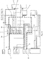
- a first current path 21 is identified in the first temporary data record, starting with the ECU 5 and continuing through the inliner 4, the fuse relay 3 to the battery 8, as shown in Figure 3 .
- the output block 13 then generates in the computer memory a first data log entry 19a of the sequence of wires 7 and components 5, 4, 3 along the first current path 21.
- specification information is recorded for each, wire 7 and component 5,4,3 logged.
- the harness identifier and branch designation is logged, together with any associated terminal connector information. Equally, in the case of components, the component identifier and terminal information is logged.
- the calculation block 12 then interrogates the wiring and component data for each intervening component 4,3 along the first current path 21 in reverse order.
- the fuse relay is 3 is interrogated first to identify any alternate current paths.
- the second output terminal 6b connected by a wire 7 is identified, as shown in Figure 4 .
- This wire is then tracked to a terminal of the generator 9.
- the component data indicates that the generator 9 has more than one output terminal
- the wiring data indicates that only one of these is connected, and therefore the calculation block may continue to track the current path from the generator 9, through a second fuse relay 23 to a second battery 28.
- the output block 13 updates the first output record 18 to record a second data log entry 19b listing the sequence of wires and intervening components along the second current path 22, in line with the information recorded in respect of the first current path 21.
- the calculation block 12 then recursively repeats the above process for the other wired terminals 6 of the ECU 5 to generate log entries 19 in the computer memory for further current paths associated with the selected component.
- the first output record 18 will contain six data log entries 19.
- Further output records 18 may also be generated for different selected starting components. For example, if the architecture 1 includes a plurality of ECUs, complete current path listings may be generated for each of them in an automated process.
- the output block 13 outputs the one or more output records in a data file stored in the computer memory which thereby provides a listing of all the current paths associated with a particular selected component, as well as the sequence of intervening components along each current path until its respective end point.
- a fault tree for assessing the failure probability of components and wiring systems may then be generated from the stored data file. For example, in the architecture shown in Figure 3 , the second, fourth and fifth current paths all route through the second fuse relay 23. Consequently, if this second fuse relay 23 has a known reference failure probability, for example based on operating parameters such as load and switching frequency, this will then influence the failure probability of the ECU 5 by virtue of its interconnection.
- the output record may indicate that the first, second and sixth current paths contain wiring which is embodied in the same section of wiring harness. If a fault is simultaneously detected in, for instance, the ECU terminals associated with the first and sixth current paths, this may then be used as an indicator of a short-circuiting issue in the associated wiring harness.
- failure detection systems may be configured to respond to the detection of such simultaneous faults. For example, even if a corresponding fault hasn't been detected in the second current path 22, and indicator of issues in both the first and sixth current paths may prompt pre-emptive maintenance repairs. In this way, faults in less critical current paths may be used to identify a high failure probability in critical components on other current paths which are only associated by virtue of their common physical location within the wiring harness assembly.
- embodiments may further comprise a fault tree generator for generating a graphical fault tree based on the output data file.
- the fault tree generator may display the generated fault tree on the computer display or output the graphic in a printable document.
- embodiments may further comprise a failure probability determination module which calculates a failure probability value for a selected starting component based on the sum of predetermined reference failure values for the intervening components in the current paths associated with the selected starting component.
- the failure probability determination module may display the calculated a failure probability value on the computer display and/or update the data file to include the failure probability values in the output records.
Landscapes
- Engineering & Computer Science (AREA)
- Physics & Mathematics (AREA)
- Geometry (AREA)
- General Physics & Mathematics (AREA)
- Theoretical Computer Science (AREA)
- Computer Hardware Design (AREA)
- General Engineering & Computer Science (AREA)
- Evolutionary Computation (AREA)
- Aviation & Aerospace Engineering (AREA)
- Pure & Applied Mathematics (AREA)
- Mathematical Optimization (AREA)
- Mathematical Analysis (AREA)
- Computational Mathematics (AREA)
- Automation & Control Theory (AREA)
- Computer Networks & Wireless Communication (AREA)
- Test And Diagnosis Of Digital Computers (AREA)
- Design And Manufacture Of Integrated Circuits (AREA)
- Debugging And Monitoring (AREA)
Abstract
Method and system for assessing component failure probability in a vehicle E/E architecture. An input block (11) receives wiring and component data (16,17). A calculation block (12) generates a first data record for a first current path starting with a first wire from a starting component and conducting through one or more intervening components to an end point. An output block (13) generates a first data log (19a) of the sequence of wires and intervening components along the first current path. The calculation block (12) also identifies alternate current paths stemming from the intervening components, and the output block (13) then updates the first data log to record the sequences of wires and intervening components along each identified alternate current path. The output block (13) outputs an output data file for fault tree analysis.
Description
- The present disclosure relates to a method and system of assessing component failure probability in a vehicle E/E architecture, and software for performing the same.
- As autonomous driving technology becomes more prevalent, the need for safer and more reliable electronic systems within vehicles increases. As a result, there has been a huge expansion in the amount of electronics included in a vehicle, with additional circuitry needed not only to implement the automated driving functions, but also to provide associated fault detection and back-up systems.
- A consequence of the above is that Electrical/Electronic (E/E) architectures in vehicles has become an increasingly important aspect of vehicle design. For this, software platforms, such as PREEvision, are typically used for E/E development to provide a model-based development environment from system design through to the final wiring harness design. PREEvision is structured in several layers, thereby allowing teams of designers having different specialisms and competencies to work within their respective layer. For example, one design team may develop the circuit design at one level within PREEvision, with the topology and wiring harness design teams then subsequently designing their aspects on different levels above this.
- In the case of the wiring harness design team, their focus is typically to minimise the cost of the wiring harness by reducing the length and weight of the cabling used to connect components within the architecture. For this, PREE vision provides a routing algorithm which calculates the shortest geometric path for segments between individual components based on the circuit topology design.
- However, an issue with the above is that the routing algorithm used for wiring harness design may not account for other factors. For instance, a potentially important issue relates to the power management of components. For example, an autonomous driving controller is reliant on inputs from an array of peripheral components, such as radars, LIDARS, and cameras etc. Consequently, any power supply irregularities to any of the peripheral components could feasibly compromise the safe operation of the controller. At the same time, the peripheral components would typically be distributed around the vehicle, and therefore will be connected through the wire harness. This is relevant because the power supply path for a particular peripheral component in a complex modern vehicle will also likely pass through hundreds of other components, wiring sections and terminals, depending not only on the wiring harness design, but also the circuit design and topology. As such, the wiring harness designer has no awareness of the impact that their harness design choices may have on the power supply for particular components. Indeed, due to the complexity of modern E/E architectures, power supply issues may only be identified during manual testing.
- The present disclosure is therefore directed to addressing these issues.
- According to a first aspect there is provided a method of assessing component failure probability in a vehicle E/E architecture, the method including the steps of: A) receiving wiring data and component data for the vehicle E/E architecture; B) selecting a starting component in the E/E architecture; C) identifying one or more terminals of the starting component using the component data; D) identifying one or more wires connected to the one or more terminals using the wiring data; E) generating a first data record for a first current path starting with a first wire and conducting through one or more intervening components to an end point, wherein the current path through each intervening component is identified based on identifying an output terminal for the respective component using the component data; F) generating a first data log of the sequence of wires and intervening components along the first current path, starting with the selected component; G) recursively interrogating the wiring and component data for each intervening component along the first current path in reverse order and updating the first data record to include one or more alternate first current paths starting with the respective intervening component and conducting through one or more intervening components to the end point or an alternate end point; H) updating the first data log to record the sequences of wires and intervening components along each identified alternate first current path; I) repeating steps E to H for any subsequent current paths starting with a subsequent wire connected to a terminal of the starting component; and J) outputting an output data file including the first and any subsequent data logs for fault tree analysis.
- In this way, the failure probability of a particular selected component arising from features of its power distribution path may be accurately assessed. For example, the output data allows relationships between intervening components and wiring in the power distribution path for a selected component to be identified across multiple levels within, for instance, a PREEvision environment. This may thereby allow failure and short-circuiting issues to be identified, and hence the development of safer E/E architectures to be facilitated.
- The method may be implemented on a computer system including a processor, a display, a user input device, and computer memory. The wiring data and component data may be stored in the computer memory. The starting component may be selected by a user using the user input device interacting with a user interface displayed on the display. The processor may execute software instructions for identifying the terminals and wires, generating the data records and data logs, and outputting an output data file by storing the data file in the computer memory. The computer memory may include different types of memory, such as RAM and storage drives. It will also be understood that the computer system may be a distributed system. For example, the wiring and component data may be stored on computer memory in a server. Furthermore, processing may be performed by a processor at the server, with a user accessing the system from a workstation having the display and user input device.
- In embodiments, the wiring data includes at least one of: circuit data for providing information regarding the connections of components within circuits, and wiring harness data for providing information regarding the connections of components through the wiring harness.
- In embodiments, the component data includes specification data for providing information regarding the internal connections and terminals of the components.
- In embodiments, the method further includes the step of generating a fault tree based on the output data file. In embodiments, the fault tree may be generated as a graphical representation for analysis.
- In embodiments, the method further includes the step of generating a failure probability value for the starting component based on the sum of reference failure values for the intervening components in the one or more current paths of the starting component.
- In embodiments, step B of selecting a starting component includes a user selection.
- In embodiments, the method further includes the step of repeating steps A to J for a second or subsequent starting component. In this way, the power distribution path information for a number of components within a vehicle's E/E architecture may be identified.
- In embodiments, the end point is one of a ground and a power source.
- In embodiments, the end point is selected by a user. In this way, a user may investigate the power distribution path or paths between two selected components.
- According to a second aspect, there is provided a non-transitory computer readable medium storing software for assessing component failure probability in a vehicle E/E architecture and including instructions which, when executed by a processor, perform the steps of: A) receiving wiring data and component data for the vehicle E/E architecture; B) selecting a starting component in the E/E architecture; C) identifying one or more terminals of the starting component using the component data; D) identifying one or more wires connected to the one or more terminals using the wiring data; E) generating a first data record for a first current path starting with a first wire and conducting through one or more intervening components to an end point, wherein the current path through each intervening component is identified based on identifying an output terminal for the respective component using the component data; F) generating a first data log of the sequence of wires and intervening components along the first current path, starting with the selected component; G) recursively interrogating the wiring and component data for each intervening component along the first current path in reverse order and updating the first data record to include one or more alternate first current paths starting with the respective intervening component and conducting through one or more intervening components to the end point or an alternate end point; H) updating the first data log to record the sequences of wires and intervening components along each identified alternate first current path; I) repeating steps E to H for any subsequent current paths starting with a subsequent wire connected to a terminal of the starting component; and J) outputting an output data file including the first and any subsequent data logs for fault tree analysis.
- In embodiments, the non-transitory computer readable medium further includes instructions which, when executed by a processor, perform the step of generating a fault tree based on the output data file.
- In embodiments, the non-transitory computer readable medium further includes instructions which, when executed by a processor, perform the step of generating a failure probability value for the starting component based on the sum of reference failure values for the intervening components in the one or more current paths of the starting component.
- According to a third aspect, there is provided system for assessing component failure probability in a vehicle E/E architecture, the system includes: an input block for receiving wiring data and component data for the vehicle E/E architecture, and for selecting a starting component in the E/E architecture; a calculation block for identifying one or more terminals of the starting component using the component data, and for identifying one or more wires connected to the one or more terminals using the wiring data, and for generating a first data record for a first current path starting with a first wire and conducting through one or more intervening components to an end point, wherein the current path through each intervening component is identified based on identifying an output terminal for the respective component using the component data; an output block for generating a first data log of the sequence of wires and intervening components along the first current path, starting with the selected component; and wherein the calculation block recursively interrogates the wiring and component data for each intervening component along the first current path in reverse order and updates the first data record to include one or more alternate first current paths starting with the respective intervening component and conducting through one or more intervening components to the end point or an alternate end point, wherein the output block updates the first data log to record the sequences of wires and intervening components along each identified alternate first current path, and wherein the calculation block generates a data log and recursively interrogates the wiring and component data for any subsequent current paths starting with a subsequent wire connected to a terminal of the starting component, and wherein the output block outputs an output data file including the first and any subsequent data logs for fault tree analysis.
- In embodiments, the system further includes a fault tree generator for generating a fault tree based on the output data file.
- In embodiments, the system further includes a failure probability determination module for generating failure probability value for the starting component based on the sum of reference failure values for the intervening components in the one or more current paths of the starting component.
- Illustrative embodiments will now be described with reference to the accompanying drawing in which:
-
Figure 1 shows a simplified diagram of the components and power distribution paths within an electrical power steering architecture; -
Figure 2 shows a schematic block diagram of a system according to first embodiment; -
Figure 3 shows a schematic diagram of the current paths identified for a selected component within the electrical power steering architecture; and -
Figure 4 shows a schematic diagram to explain the identification of the first and second current paths shown inFigure 3 . - An illustrative embodiment of a software system for assessing component failure probability in a vehicle E/E architecture is described below. The software and method is described in relation to an example electrical / electronic architecture, in this case being the vehicle's electrical power steering architecture. However, it will be understood that the invention may be applied to other vehicle E/E architectures.
-
Figure 1 shows a simplified diagram of the components and power distribution paths within thepower steering architecture 1. The components include, for example, electronic control units (ECU) 5,inliners 5,fuse relay boxes 3,generators 9, and actuators. Each component may include a plurality ofterminals 6, and various components are connected to one another via theterminals 6 throughwires 7. Switches within the components may connect different components with one another during different operating conditions. - In this embodiment, the
power steering architecture 1 is developed in PREEvision and includes data representing thewiring 7 between components and specification data for the components themselves. - The wiring data includes data representing both connections through the wiring harness and circuit board connections, albeit that these would be visualised in different layers within PREEvision. For example, whilst two components may appear adjacent in the circuit diagram, in reality they may be separated by meters of wiring harness and be routed through various terminal connectors and distribution blocks.
- The component data includes data representing the terminal connections for that component, as well as information regarding switchable connections between different terminals. That is, some components may have two terminals, which may be represented as an input and an output. However, other components may have three or more terminals, for instance to provide alternative outputs when in certain switching configurations. Again, aspects of this component information may be visualised in different layers within PREEvision.
-
Figure 2 shows a schematic block diagram of asoftware system 10 according to the illustrative embodiment. In this embodiment, thesystem 10 is provided as a JAVA module plug-in for PREEvision. Thesystem 10 includes aninput block 11 which feeds inputs to acalculation block 12, which in turn generates output data throughoutput block 13. Theinput block 11,calculation block 12, andoutput block 13 are executed by a processor of a computer system. Theinput block 11 may receive inputs from a user input device, such as a mouse, and display a user interface on a computer display for facilitating user selections. Theinput block 11,calculation block 12, andoutput block 13 may access computer memory for reading wiring and component data, as well as reading and writing record data and log data. - The
input block 14 includes acomponent selection section 14 for selecting a starting component. Thecomponent selection section 14 presents the user interface on the computer display within the PREEvision environment for a user to make selections and set parameters for the process. In this embodiment, the user manually selects a starting component. In other embodiments, thecomponent selection section 14 may automatically select a starting component. For example, thesystem 10 may select components in turn from a group of components fitting a particular classification, such as ECUs. - The
input block 14 further includes an endpoint designation section 15. In this embodiment, all grounding terminals and battery terminals are designated as end points by default. However, in other embodiments, a user may manually select a specific point in the architecture as a designated end point to allow assessment between two selected points. - The
input block 14 further receives wiring and component data from the PREEvision model through awiring data section 16 andcomponent data section 17, respectively. Thewiring data section 16 andcomponent data section 17 access the wiring and component data from the computer memory. - Based on the output of the
calculation block 12, theoutput block 13 generates one ormore output records 18 which include current path entries 19, as is described in further detail below. - The method employed when the
software representing system 10 is executed will now be described with reference toFigures 2-4 . Theinput block 11 receives the wiring and component data though thewiring data section 16 andcomponent data section 17. A user selects a starting component though thecomponent selection section 14. In this example, theECU 5 is designated as the starting component. - The
calculation block 12 identifies theterminals 6 of theECU 5 using the component data. The ECU'sfirst terminal 6 connected to awire 7 is identified using the wiring data, and a first temporary data record is generated in the computer memory in respect of a first current path starting with the ECU'sfirst terminal 6. - The
calculation block 12 then tracks thewire 7 connected to thefirst terminal 6 to theinliner 4. Theinliner 6 only has two terminals and therefore theoutput terminal 6 is easily identified by thecalculation block 12 to allow the tracking to progress to the next component, which isfuse relay 3. In this instance, thecalculation block 12 determines from the component data that thefuse relay 3 includes a plurality of terminals, with two being output terminals relevant to the particular input terminal connected to theinliner 4. Thecalculation block 12 selects thefirst output terminal 6a, logs this in the first temporary data record, and continues on to thebattery 8, which is a designated end point. As such, a firstcurrent path 21 is identified in the first temporary data record, starting with theECU 5 and continuing through theinliner 4, thefuse relay 3 to thebattery 8, as shown inFigure 3 . - The
output block 13 then generates in the computer memory a firstdata log entry 19a of the sequence ofwires 7 andcomponents current path 21. For each,wire 7 andcomponent wires 7 which are embodied in a physical wiring harness, the harness identifier and branch designation is logged, together with any associated terminal connector information. Equally, in the case of components, the component identifier and terminal information is logged. - Once the first
data log entry 19a for the first current path has been completed, thecalculation block 12 then interrogates the wiring and component data for each interveningcomponent current path 21 in reverse order. As such, the fuse relay is 3 is interrogated first to identify any alternate current paths. In this example, thesecond output terminal 6b connected by awire 7 is identified, as shown inFigure 4 . This wire is then tracked to a terminal of thegenerator 9. Although the component data indicates that thegenerator 9 has more than one output terminal, the wiring data indicates that only one of these is connected, and therefore the calculation block may continue to track the current path from thegenerator 9, through asecond fuse relay 23 to asecond battery 28. This therefore identifies a secondcurrent path 22, which follows the same route as the firstcurrent path 21 from theECU 5, through theinliner 4, until thefuse relay 3, but then follows an alternate route from thesecond terminal 6b, through thegenerator 9 andsecond fuse relay 23 to thesecond battery 28, as shown inFigure 4 . - Once the second
current path 22 is identified, theoutput block 13 updates thefirst output record 18 to record a seconddata log entry 19b listing the sequence of wires and intervening components along the secondcurrent path 22, in line with the information recorded in respect of the firstcurrent path 21. - The
calculation block 12 then recursively repeats the above process for the otherwired terminals 6 of theECU 5 to generate log entries 19 in the computer memory for further current paths associated with the selected component. In this example, six further current paths are identified, as shown inFigure 3 . As such, thefirst output record 18 will contain six data log entries 19.Further output records 18 may also be generated for different selected starting components. For example, if thearchitecture 1 includes a plurality of ECUs, complete current path listings may be generated for each of them in an automated process. - The
output block 13 outputs the one or more output records in a data file stored in the computer memory which thereby provides a listing of all the current paths associated with a particular selected component, as well as the sequence of intervening components along each current path until its respective end point. A fault tree for assessing the failure probability of components and wiring systems may then be generated from the stored data file. For example, in the architecture shown inFigure 3 , the second, fourth and fifth current paths all route through thesecond fuse relay 23. Consequently, if thissecond fuse relay 23 has a known reference failure probability, for example based on operating parameters such as load and switching frequency, this will then influence the failure probability of theECU 5 by virtue of its interconnection. - Furthermore, in another example, the output record may indicate that the first, second and sixth current paths contain wiring which is embodied in the same section of wiring harness. If a fault is simultaneously detected in, for instance, the ECU terminals associated with the first and sixth current paths, this may then be used as an indicator of a short-circuiting issue in the associated wiring harness. As such, failure detection systems may be configured to respond to the detection of such simultaneous faults. For example, even if a corresponding fault hasn't been detected in the second
current path 22, and indicator of issues in both the first and sixth current paths may prompt pre-emptive maintenance repairs. In this way, faults in less critical current paths may be used to identify a high failure probability in critical components on other current paths which are only associated by virtue of their common physical location within the wiring harness assembly. - In this connection, embodiments may further comprise a fault tree generator for generating a graphical fault tree based on the output data file. The fault tree generator may display the generated fault tree on the computer display or output the graphic in a printable document. Similarly, embodiments may further comprise a failure probability determination module which calculates a failure probability value for a selected starting component based on the sum of predetermined reference failure values for the intervening components in the current paths associated with the selected starting component. The failure probability determination module may display the calculated a failure probability value on the computer display and/or update the data file to include the failure probability values in the output records.
- It will be understood that the illustrative example E/E architecture above has been significantly simplified. In practice, vehicle E/E architectures will often comprise thousands of components, and include wiring harnesses with tens of branches and terminal connectors. In this context, the above system nevertheless allows relationships between components and wiring to be identified across multiple levels within the PREEvision environment. In turn, this allows for the assessment of failure probability of different components arising from features of their power distribution paths, not only encompassing awareness of components along that path, but also the physical and geometric relationships between components, component terminals and wiring sections. In turn, this provides for the development of safer E/E architectures.
- It will be understood that the embodiment illustrated above show applications only for the purposes of illustration. In practice, embodiments may be applied to many different configurations, the detail of which being straightforward for those skilled in the art to implement.
Claims (15)
- A method of assessing component failure probability in a vehicle E/E architecture, the method comprising the steps of:A) receiving wiring data and component data for the vehicle E/E architecture;B) selecting a starting component in the E/E architecture;C) identifying one or more terminals of the starting component using the component data;D) identifying one or more wires connected to the one or more terminals using the wiring data;E) generating a first data record for a first current path starting with a first wire and conducting through one or more intervening components to an end point, wherein the current path through each intervening component is identified based on identifying an output terminal for the respective component using the component data;F) generating a first data log of the sequence of wires and intervening components along the first current path, starting with the selected component;G) recursively interrogating the wiring and component data for each intervening component along the first current path in reverse order and updating the first data record to include one or more alternate first current paths starting with the respective intervening component and conducting through one or more intervening components to the end point or an alternate end point;H) updating the first data log to record the sequences of wires and intervening components along each identified alternate first current path;I) repeating steps E to H for any subsequent current paths starting with a subsequent wire connected to a terminal of the starting component; andJ) outputting an output data file including the first and any subsequent data logs for fault tree analysis.
- A method according to claim 1, wherein the wiring data comprises at least one of:circuit data for providing information regarding the connections of components within circuits, andwiring harness data for providing information regarding the connections of components through the wiring harness.
- A method according to claim 1 or 2, wherein the component data comprises specification data for providing information regarding the internal connections and terminals of the components.
- A method according to any preceding claim, further comprising the step of generating a fault tree based on the output data file.
- A method according to any preceding claim, further comprising the step of generating a failure probability value for the starting component based on the sum of reference failure values for the intervening components in the one or more current paths of the starting component.
- A method according to any preceding claim, wherein step B of selecting a starting component comprises a user selection.
- A method according to any preceding claim, further comprising the step of repeating steps A to J for a second or subsequent starting component.
- A method according to any preceding claim, wherein the end point is one of a ground and a power source.
- A method according to any preceding claim, wherein the end point is selected by a user.
- A non-transitory computer readable medium storing software for assessing component failure probability in a vehicle E/E architecture and comprising instructions which, when executed by a processor, perform the steps of:A) receiving wiring data and component data for the vehicle E/E architecture;B) selecting a starting component in the E/E architecture;C) identifying one or more terminals of the starting component using the component data;D) identifying one or more wires connected to the one or more terminals using the wiring data;E) generating a first data record for a first current path starting with a first wire and conducting through one or more intervening components to an end point, wherein the current path through each intervening component is identified based on identifying an output terminal for the respective component using the component data;F) generating a first data log of the sequence of wires and intervening components along the first current path, starting with the selected component;G) recursively interrogating the wiring and component data for each intervening component along the first current path in reverse order and updating the first data record to include one or more alternate first current paths starting with the respective intervening component and conducting through one or more intervening components to the end point or an alternate end point;H) updating the first data log to record the sequences of wires and intervening components along each identified alternate first current path;I) repeating steps E to H for any subsequent current paths starting with a subsequent wire connected to a terminal of the starting component; andJ) outputting an output data file including the first and any subsequent data logs for fault tree analysis.
- A non-transitory computer readable medium according to claim 10, further comprising instructions which, when executed by a processor, perform the step of generating a fault tree based on the output data file.
- A non-transitory computer readable medium according to claim 10 or 11, further comprising instructions which, when executed by a processor, perform the step of generating a failure probability value for the starting component based on the sum of reference failure values for the intervening components in the one or more current paths of the starting component.
- A system for assessing component failure probability in a vehicle E/E architecture, the system comprising:an input block for receiving wiring data and component data for the vehicle E/E architecture, and for selecting a starting component in the E/E architecture;a calculation block for identifying one or more terminals of the starting component using the component data, and for identifying one or more wires connected to the one or more terminals using the wiring data, and for generating a first data record for a first current path starting with a first wire and conducting through one or more intervening components to an end point, wherein the current path through each intervening component is identified based on identifying an output terminal for the respective component using the component data;an output block for generating a first data log of the sequence of wires and intervening components along the first current path, starting with the selected component; andwherein the calculation block recursively interrogates the wiring and component data for each intervening component along the first current path in reverse order and updates the first data record to include one or more alternate first current paths starting with the respective intervening component and conducting through one or more intervening components to the end point or an alternate end point,wherein the output block updates the first data log to record the sequences of wires and intervening components along each identified alternate first current path, andwherein the calculation block generates a data log and recursively interrogates the wiring and component data for any subsequent current paths starting with a subsequent wire connected to a terminal of the starting component, andwherein the output block outputs an output data file including the first and any subsequent data logs for fault tree analysis.
- A system according to claim 13, further comprising a fault tree generator for generating a fault tree based on the output data file.
- A system according to claim 13 or 14, further comprising a failure probability determination module for generating failure probability value for the starting component based on the sum of reference failure values for the intervening components in the one or more current paths of the starting component.
Priority Applications (4)
| Application Number | Priority Date | Filing Date | Title |
|---|---|---|---|
| EP20204322.0A EP3992831A1 (en) | 2020-10-28 | 2020-10-28 | Method, system and software for assessing component failure probability in a vehicle e/e architecture |
| EP21202285.9A EP3992832A1 (en) | 2020-10-28 | 2021-10-12 | Method, system and software for selecting an optimal e/e arrangement |
| CN202111256209.0A CN114487636A (en) | 2020-10-28 | 2021-10-27 | Method, system and software for selecting optimal electrical/electronic structure |
| US17/512,522 US20220129599A1 (en) | 2020-10-28 | 2021-10-27 | Method, System and Software for Selecting an E/E Arrangement |
Applications Claiming Priority (1)
| Application Number | Priority Date | Filing Date | Title |
|---|---|---|---|
| EP20204322.0A EP3992831A1 (en) | 2020-10-28 | 2020-10-28 | Method, system and software for assessing component failure probability in a vehicle e/e architecture |
Publications (1)
| Publication Number | Publication Date |
|---|---|
| EP3992831A1 true EP3992831A1 (en) | 2022-05-04 |
Family
ID=73037759
Family Applications (2)
| Application Number | Title | Priority Date | Filing Date |
|---|---|---|---|
| EP20204322.0A Withdrawn EP3992831A1 (en) | 2020-10-28 | 2020-10-28 | Method, system and software for assessing component failure probability in a vehicle e/e architecture |
| EP21202285.9A Pending EP3992832A1 (en) | 2020-10-28 | 2021-10-12 | Method, system and software for selecting an optimal e/e arrangement |
Family Applications After (1)
| Application Number | Title | Priority Date | Filing Date |
|---|---|---|---|
| EP21202285.9A Pending EP3992832A1 (en) | 2020-10-28 | 2021-10-12 | Method, system and software for selecting an optimal e/e arrangement |
Country Status (3)
| Country | Link |
|---|---|
| US (1) | US20220129599A1 (en) |
| EP (2) | EP3992831A1 (en) |
| CN (1) | CN114487636A (en) |
Families Citing this family (1)
| Publication number | Priority date | Publication date | Assignee | Title |
|---|---|---|---|---|
| JP7410113B2 (en) * | 2021-12-23 | 2024-01-09 | 住友電装株式会社 | electrical connection unit |
Family Cites Families (5)
| Publication number | Priority date | Publication date | Assignee | Title |
|---|---|---|---|---|
| CA2360291A1 (en) * | 2001-10-30 | 2003-04-30 | Benoit Nadeau-Dostie | Method and program product for designing hierarchical circuit for quiescent current testing and circuit produced thereby |
| FR2846117B1 (en) * | 2002-10-21 | 2008-08-22 | Renault Sas | METHOD AND DEVICE FOR SYNTHESIZING AN ELECTRICAL ARCHITECTURE |
| US10539955B2 (en) * | 2012-06-15 | 2020-01-21 | The Boeing Company | Failure analysis validation and visualization |
| US20200167442A1 (en) * | 2018-11-27 | 2020-05-28 | The Boeing Company | Apparatus and method of processor-aided wiring of components of an electrical system |
| CN110766137A (en) * | 2019-10-18 | 2020-02-07 | 武汉大学 | Power electronic circuit fault diagnosis method based on longicorn whisker optimized deep confidence network algorithm |
-
2020
- 2020-10-28 EP EP20204322.0A patent/EP3992831A1/en not_active Withdrawn
-
2021
- 2021-10-12 EP EP21202285.9A patent/EP3992832A1/en active Pending
- 2021-10-27 US US17/512,522 patent/US20220129599A1/en not_active Abandoned
- 2021-10-27 CN CN202111256209.0A patent/CN114487636A/en active Pending
Non-Patent Citations (4)
| Title |
|---|
| "Flow Networks", 1 January 2013, ELSEVIER, ISBN: 978-0-12-398396-1, article TODINOV MICHAEL T.: "Topology Optimisation of Repairable Flow Networks and Reliability Networks", pages: 1 - 247, XP055790200, DOI: 10.1016/B978-0-12-398396-1.00011-8 * |
| SHU XIONG ET AL: "A Detailed Reliability Study of the Motor System in Pure Electric Vans by the Approach of Fault Tree Analysis", IEEE ACCESS, IEEE, USA, vol. 8, 31 December 2019 (2019-12-31), pages 5295 - 5307, XP011764772, DOI: 10.1109/ACCESS.2019.2963197 * |
| U.S. MILITARY: "U.S. MIL Specification: MIL-HDBK-217F: Military Handbook - Reliability Prediction of Electronic Equipment", 2 December 1991 (1991-12-02), XP055790198, Retrieved from the Internet <URL:http://nomtbf.com/wp-content/uploads/2015/01/MIL-HDBK-217F-Notice2.pdf> [retrieved on 20210325] * |
| VECTOR: "Development of Functional Safe Systems using PREEvision", 7 November 2018 (2018-11-07), XP055790315, Retrieved from the Internet <URL:https://assets.vector.com/cms/content/events/2018/Webinars18/Vector_Webinar_FuSi_using_PREEvision_20181107.pdf> [retrieved on 20210326] * |
Also Published As
| Publication number | Publication date |
|---|---|
| CN114487636A (en) | 2022-05-13 |
| EP3992832A1 (en) | 2022-05-04 |
| US20220129599A1 (en) | 2022-04-28 |
Similar Documents
| Publication | Publication Date | Title |
|---|---|---|
| CN108563214B (en) | Vehicle diagnosis method, device and equipment | |
| CN102801552B (en) | The system and method alleviated for mistake isolation and mistake of modeling Network Based | |
| US9435843B2 (en) | Wire harness continuity inspection device, wire harness continuity inspection program, and wire harness continuity inspection method | |
| JP5550455B2 (en) | Wire harness continuity inspection method and wire harness continuity inspection program | |
| JP5605540B2 (en) | Wire harness continuity inspection method and wire harness continuity inspection program | |
| JP5586325B2 (en) | Wire harness continuity inspection method and wire harness continuity inspection program | |
| US9272674B2 (en) | Wire harness continuity inspection device, wire harness continuity inspection program, and wire harness continuity inspection method | |
| CN113311802A (en) | Vehicle electronic repair and diagnostic system and method | |
| US20150241498A1 (en) | Method of determining possibly-unused electric wire and program | |
| US10591529B2 (en) | Wiring safety evaluation system and wiring safety evaluation method | |
| EP3992832A1 (en) | Method, system and software for selecting an optimal e/e arrangement | |
| CN114610555B (en) | Fault diagnosis method of equipment and fault diagnosis equipment | |
| US20150379788A1 (en) | Method for managing fault messages of a motor vehicle | |
| KR20050039349A (en) | Method of physically verifying wiring harness for vehicle | |
| US9684024B2 (en) | Method for determining unmated connector and program | |
| US10101380B2 (en) | Device for determining electrical wire bundle | |
| JP5557384B2 (en) | Wire harness continuity inspection method and wire harness continuity inspection program | |
| JP2016128996A (en) | Inspection method of wiring diagram data | |
| JP2020160580A (en) | Connection status detection method, connection status detection program and design support device | |
| Xu et al. | Wire Segment Error Locating Algorithm for Wiring Connection Verification Tool | |
| 서건 et al. | Error Wire Locating Technology with Breadth-first Search Algorithm |
Legal Events
| Date | Code | Title | Description |
|---|---|---|---|
| PUAI | Public reference made under article 153(3) epc to a published international application that has entered the european phase |
Free format text: ORIGINAL CODE: 0009012 |
|
| STAA | Information on the status of an ep patent application or granted ep patent |
Free format text: STATUS: THE APPLICATION HAS BEEN PUBLISHED |
|
| AK | Designated contracting states |
Kind code of ref document: A1 Designated state(s): AL AT BE BG CH CY CZ DE DK EE ES FI FR GB GR HR HU IE IS IT LI LT LU LV MC MK MT NL NO PL PT RO RS SE SI SK SM TR |
|
| STAA | Information on the status of an ep patent application or granted ep patent |
Free format text: STATUS: THE APPLICATION IS DEEMED TO BE WITHDRAWN |
|
| RAP3 | Party data changed (applicant data changed or rights of an application transferred) |
Owner name: APTIV TECHNOLOGIES LIMITED |
|
| 18D | Application deemed to be withdrawn |
Effective date: 20221105 |