EP3992643A1 - Methods and systems for determining a state of an arrangement of electric and/or electronic components - Google Patents
Methods and systems for determining a state of an arrangement of electric and/or electronic components Download PDFInfo
- Publication number
- EP3992643A1 EP3992643A1 EP20205139.7A EP20205139A EP3992643A1 EP 3992643 A1 EP3992643 A1 EP 3992643A1 EP 20205139 A EP20205139 A EP 20205139A EP 3992643 A1 EP3992643 A1 EP 3992643A1
- Authority
- EP
- European Patent Office
- Prior art keywords
- load current
- arrangement
- implemented method
- computer implemented
- current measurements
- Prior art date
- Legal status (The legal status is an assumption and is not a legal conclusion. Google has not performed a legal analysis and makes no representation as to the accuracy of the status listed.)
- Granted
Links
Images






Classifications
-
- G—PHYSICS
- G01—MEASURING; TESTING
- G01R—MEASURING ELECTRIC VARIABLES; MEASURING MAGNETIC VARIABLES
- G01R22/00—Arrangements for measuring time integral of electric power or current, e.g. electricity meters
- G01R22/06—Arrangements for measuring time integral of electric power or current, e.g. electricity meters by electronic methods
-
- G—PHYSICS
- G06—COMPUTING OR CALCULATING; COUNTING
- G06N—COMPUTING ARRANGEMENTS BASED ON SPECIFIC COMPUTATIONAL MODELS
- G06N3/00—Computing arrangements based on biological models
- G06N3/02—Neural networks
- G06N3/08—Learning methods
-
- G—PHYSICS
- G06—COMPUTING OR CALCULATING; COUNTING
- G06F—ELECTRIC DIGITAL DATA PROCESSING
- G06F18/00—Pattern recognition
- G06F18/20—Analysing
- G06F18/24—Classification techniques
- G06F18/241—Classification techniques relating to the classification model, e.g. parametric or non-parametric approaches
-
- G—PHYSICS
- G06—COMPUTING OR CALCULATING; COUNTING
- G06N—COMPUTING ARRANGEMENTS BASED ON SPECIFIC COMPUTATIONAL MODELS
- G06N3/00—Computing arrangements based on biological models
- G06N3/02—Neural networks
- G06N3/04—Architecture, e.g. interconnection topology
-
- G—PHYSICS
- G06—COMPUTING OR CALCULATING; COUNTING
- G06N—COMPUTING ARRANGEMENTS BASED ON SPECIFIC COMPUTATIONAL MODELS
- G06N3/00—Computing arrangements based on biological models
- G06N3/02—Neural networks
- G06N3/04—Architecture, e.g. interconnection topology
- G06N3/044—Recurrent networks, e.g. Hopfield networks
-
- G—PHYSICS
- G06—COMPUTING OR CALCULATING; COUNTING
- G06N—COMPUTING ARRANGEMENTS BASED ON SPECIFIC COMPUTATIONAL MODELS
- G06N3/00—Computing arrangements based on biological models
- G06N3/02—Neural networks
- G06N3/04—Architecture, e.g. interconnection topology
- G06N3/044—Recurrent networks, e.g. Hopfield networks
- G06N3/0442—Recurrent networks, e.g. Hopfield networks characterised by memory or gating, e.g. long short-term memory [LSTM] or gated recurrent units [GRU]
-
- G—PHYSICS
- G06—COMPUTING OR CALCULATING; COUNTING
- G06N—COMPUTING ARRANGEMENTS BASED ON SPECIFIC COMPUTATIONAL MODELS
- G06N3/00—Computing arrangements based on biological models
- G06N3/02—Neural networks
- G06N3/04—Architecture, e.g. interconnection topology
- G06N3/045—Combinations of networks
-
- G—PHYSICS
- G06—COMPUTING OR CALCULATING; COUNTING
- G06N—COMPUTING ARRANGEMENTS BASED ON SPECIFIC COMPUTATIONAL MODELS
- G06N3/00—Computing arrangements based on biological models
- G06N3/02—Neural networks
- G06N3/04—Architecture, e.g. interconnection topology
- G06N3/0464—Convolutional networks [CNN, ConvNet]
-
- G—PHYSICS
- G06—COMPUTING OR CALCULATING; COUNTING
- G06N—COMPUTING ARRANGEMENTS BASED ON SPECIFIC COMPUTATIONAL MODELS
- G06N3/00—Computing arrangements based on biological models
- G06N3/02—Neural networks
- G06N3/08—Learning methods
- G06N3/09—Supervised learning
-
- G—PHYSICS
- G01—MEASURING; TESTING
- G01R—MEASURING ELECTRIC VARIABLES; MEASURING MAGNETIC VARIABLES
- G01R31/00—Arrangements for testing electric properties; Arrangements for locating electric faults; Arrangements for electrical testing characterised by what is being tested not provided for elsewhere
- G01R31/005—Testing of electric installations on transport means
- G01R31/006—Testing of electric installations on transport means on road vehicles, e.g. automobiles or trucks
- G01R31/007—Testing of electric installations on transport means on road vehicles, e.g. automobiles or trucks using microprocessors or computers
-
- G—PHYSICS
- G06—COMPUTING OR CALCULATING; COUNTING
- G06N—COMPUTING ARRANGEMENTS BASED ON SPECIFIC COMPUTATIONAL MODELS
- G06N20/00—Machine learning
-
- G—PHYSICS
- G06—COMPUTING OR CALCULATING; COUNTING
- G06N—COMPUTING ARRANGEMENTS BASED ON SPECIFIC COMPUTATIONAL MODELS
- G06N3/00—Computing arrangements based on biological models
- G06N3/02—Neural networks
Definitions
- the present disclosure relates to methods and systems for determining a state of an arrangement of electric and/or electronic components.
- Input currents of different loads and consumers are commonly supplied by relays and melting fuses, which however provide a slow and error-prone way of cutting loads and consumers from a current source.
- the present disclosure provides a computer implemented method, a computer system, a vehicle, a battery charger, and a non-transitory computer readable medium according to the independent claims. Embodiments are given in the subclaims, the description and the drawings.
- the present disclosure is directed at a computer implemented method for determining a state of an arrangement of electric and/or electronic components, the method comprising the following steps performed (in other words: carried out) by computer hardware components: determining a plurality of load current measurements of the arrangement; providing the plurality of load current measurements to a machine learning method; and determining the state of the arrangement based on the plurality of load current measurements using the machine learning method.
- the load current is a current, for example a current is related to power consumed by one or more loads.
- the method may provide a smart fuse technology for mainly automotive purpose using artificial neural networks.
- the method may improve and solve many problems of prior art techniques such as: being more focused on application peripherals and parameters of attached components like loads, wire harness and supply voltages; more flexible against environmental changes since there is no static threshold being compared to monitored current level; according to environmental changes (e.g. temperatures) the model can directly be exchanged by software; more complex current profile trends can be taken into account without loading processor CPU; and more detailed trend indications can be analyzed with smaller effort in the field application. Mainly decreased processor performance needed.
- determining the state of the arrangement comprises classifying the state of the arrangement into one of a plurality of classes.
- the classes comprise a class of overload state and a class of non-overload state.
- the method may be provided to provide input to an electronic fuse, for example a power switch, to determine overload situations, in which the switch shall disconnect the load from the supply.
- the classes comprise a class of fully charged and a class of not fully charged, or the classes comprise a plurality of classes corresponding to pre-determined percentages of full charging (for example classes for 0%, 25,%, 50%, 75%, and 100% of full charging, or classes of 0%, 10%, 20%, 30%, 40%, 50%, 60%, 70%, 80%, 90%, and 100% of full charging).
- the method may be provided for controlling charging, for example charging of a battery, for example a battery of a vehicle.
- the plurality of load current measurements comprises a plurality of series of load current measurements, each series comprising a pre-determined number of subsequent load current measurements.
- the pre-determined number of subsequent load current measurements may be provided subsequently in time.
- Each series may be referred to as a snapshot.
- the plurality of series may overlap in time. This may ensure that each of the plurality of load current measurements are treated in the context of the neighboring load current measurements.
- the machine learning method comprises a method using an artificial neural network.
- a load current profile classification with neural network implementation may be provided, for example for smart fusing.
- the smart fuse arrangement may be provided using a machine learning approach trained using an electronic load current profile classification system.
- the artificial neural network comprises a convolutional neural network.
- the convolutional neural network comprises a network with a 3x3 cascade.
- the artificial neural network comprises a long short-term memory.
- the present disclosure is directed at a computer system, said computer system comprising a plurality of computer hardware components configured to carry out several or all steps of the computer implemented method described herein.
- the computer system may comprise a plurality of computer hardware components (for example a processor, for example processing unit or processing network, at least one memory, for example memory unit or memory network, and at least one non-transitory data storage). It will be understood that further computer hardware components may be provided and used for carrying out steps of the computer implemented method in the computer system.
- the non-transitory data storage and/or the memory unit may comprise a computer program for instructing the computer to perform several or all steps or aspects of the computer implemented method described herein, for example using the processing unit and the at least one memory unit.
- the computer system further comprises a digital signal processor configured to carry out the machine learning method.
- the present disclosure is directed at a vehicle comprising the computer system described herein and a sensor configured to determine the plurality of load current measurements of the arrangement.
- the present disclosure is directed at a battery charger comprising the computer system as described herein and a sensor configured to determine the plurality of load current measurements of the arrangement.
- the battery charger may further include a voltage sensor configured to determine a voltage of the arrangement.
- the battery charger may further include a temperature r sensor configured to determine a temperature of the arrangement. The state of the arrangement may then be determined further based on the voltage and/or the temperature.
- the arrangement may be a battery.
- the battery charger may control a current provided to the battery, for example using a pulse width modulation (PWM) of a current.
- PWM pulse width modulation
- the present disclosure is directed at a non-transitory computer readable medium comprising instructions for carrying out several or all steps or aspects of the computer implemented method described herein.
- the computer readable medium may be configured as: an optical medium, such as a compact disc (CD) or a digital versatile disk (DVD); a magnetic medium, such as a hard disk drive (HDD); a solid state drive (SSD); a read only memory (ROM), such as a flash memory; or the like.
- the computer readable medium may be configured as a data storage that is accessible via a data connection, such as an internet connection.
- the computer readable medium may, for example, be an online data repository or a cloud storage.
- Various aspects may be applicable for replacing electronic relay and fusing systems, and may be applicable for power supplies on vehicle system level or ECU (electronic control unit) internally (for example for the power tree).
- ECU electronic control unit
- Various aspects may provide a high performance smart fusing, and may provide an adaptable and intelligent switching and fusing which allows small margins for power tree and W/H (wiring harness).
- the present disclosure is also directed at a computer program for instructing a computer to perform several or all steps or aspects of the computer implemented method described herein.
- Input currents of different loads and consumers within the vehicle are commonly supplied by relays and melting fuses since.
- electronic circuits may observe the load current and may detach the load from wiring harness of a vehicle in case of overcurrent detection.
- an intelligent and adaptable way is provided to ensure highest load availability for increasing protection level of the wiring harness and to be flexible enough against environmental changes.
- Various embodiments may improve standard fusing devices, smart fusing devices and existing circuits for protecting the wiring harness and attached loads against overcurrents and even short circuits.
- Various embodiments may be used for systems and module features needed in future beside fusing strategies, where short reaction times and adaptability to changes of a physical value within a certain time (profiles) should be applied.
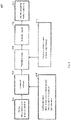
- Fig. 1 shows a block diagram 100 illustrating an electronic load current profile classification system according to various embodiments, for example using circuit components and a heterogeneous microprocessor structure, including a neural network accelerator 112 (which may include a neural processing unit and/or a numeric processing unit and/or a DSP (digital signal processor), and which may provide profile classification).
- a neural network accelerator 112 which may include a neural processing unit and/or a numeric processing unit and/or a DSP (digital signal processor), and which may provide profile classification).
- DSP digital signal processor
- Incoming samples of a load current measurement 102 may be handled by an Analog-to-Digital-Converter (ADC) module 104.
- the samples may be taken in equal time intervals dt and may be handed over to a central processing unit 106 (which may be referred to as a processor).
- the samples may include integer values, which may be buffered into a random access memory (RAM) storage 110.
- the samples may be (directly) provided from the ADC 106 to the RAM 110 by DMA 116 (direct memory access).
- the RAM storage 110 may be configured as ringbuffer structures of several counts. Every filled buffer may contain a snapshot of the measured current profile.
- DMA may be used for ADC data exchange to RAM fetched by the NPU/DSP unit.
- Fig. 2 shows an illustration 200 of overlap of load current measurements in various snapshots.
- a real (or actual) current profile 202 is shown, and three profile snapshots 204, 206, 208 which may be stored in three buffers, are illustrated. There is a (temporal) overlap between the snapshots.
- a neural network computing unit 112 may fetch the contents of the several ring buffers from the RAM 110, and may classify the contents using a pretrained CNN (for example a convolutional neural network or a cellular neural network)) model 114.
- a pretrained CNN for example a convolutional neural network or a cellular neural network
- the (artificial) neural network may be a CNN constellated as 3x3 cascade.
- LSTM long short-term memory
- LSTM long short-term memory
- the (artificial) neural network may receive a time series of measurement data.
- the (artificial) neural network may receive measurement data for each time individually, and may have an internal memory; for example, the (artificial) neural network may be a recurrent neural network (RNN).
- RNN recurrent neural network
- the pretrained model 114 may be generated out of several tens and hundreds of measured load current profiles in laboratory test fields, for example generated with application specific wiring harness, supply parameters and load properties.
- the classification reflects a certain probability that the pretrained CNN model 114 is overlapping with buffer contents
- this result may be reported as positive detection to the processor CPU 106 (which may act as a safety controller).
- the method may then be receiving this signal and may decide how to react.
- the absolute current level may additionally be checked, for example by a state machine.
- the pretrained model 114 may mainly be focused on certain trends that will probably lead to overcurrents caused by failures or even short circuits to realize wireguard system that is fast enough to protect the wiring harness before overheating.
- a following state machine may be used for failure mitigation in case the CNN accelerator 112 is signaling an overcurrent trend.
- the CPU may control a power switch 108, for example a power MOSFET (metal oxide semiconductor field-effect transistor) switch.
- a power MOSFET metal oxide semiconductor field-effect transistor
- a first step to generate a machine learning model data from the field application may be taken.
- the same components of the wiring system may be used and a continuous measurement may be realized to record all possible behaviors on the line.
- FIG. 3 shows an illustration 300 of a physical measurement and logging procedure according to various embodiments.
- a current measurement 302 may be provided to data logging 304, and based on the logged data, a database (for example including raw data) may be generated (306).
- Fig. 4 shows an illustration 400 of how a machine learning model (for example a neural network) is trained.
- a machine learning problem may be defined and a solution may be proposed.
- a data set may be constructed.
- raw data may be collected, feature and label sources may be identified, a sampling strategy may be selected, and the data may be split.
- data may be transformed.
- data may be explored and cleaned and feature engineering may be performed.
- the machine learning model may be trained.
- the (trained) machine learning model may be used to make predictions.
- Fig. 5 shows an illustration 500 of a plurality of samples of load current.
- the high peak current values should trigger the fuse function of the system. It can be seen that the current is shortly increased and lowers itself afterwards. It then reaches an average current which was slightly higher than in the beginning of the scenario. Those logged datasets are used to train a neural network in the next step.
- a verification script may be generated that binds in the machine learning model as .tflite file and executes it with an arbitrary test current profile. This approach may be seen as a kind of model validation, to see if the idea behind this concept works fine.
- Fig. 6 shows an illustration 600 of two verification profiles for both triggering and non-triggering current profile.
- a first profile 604 shows a profile sample on which the controller should enable the fusing mechanism: Detection probability was calculated with 95% by the trained model.
- a second profile 602 shows a profile sample on which the controller should not enable the fusing mechanism an current proceeds to flow: Detection probability was calculated with 5% by the trained model.
- the model may be used on a microcontroller system. As soon as the model is trained and validated, it may be deployed on a microprocessor or even microcontroller system. In case a smaller controller should be used, tensorflow-lite micro libraries may be used, which may be focused on supporting those systems with smaller memory and computation capabilities.
- neural nets may be used for recognizing current profiles, to be prealarmed for possible faults on the supply system.
- the neural net may be trained with existing measurement samples and a model may be generated that knows that such profiles can exist in case a module changes its internal function (for example when the current increases shortly). It may be the case that the current level exceeds a specific limit of capabilities, e.g. wiring harness current load, but only for very short time.
- the model can be trained to be prealarmed if such increases are presen.t
- the model and the microcontroller may be smart enough to detect it as unregularity and protect load as well as wiring harness by switching off the supply path.
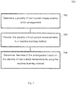
- Fig. 7 shows a flow diagram 700 illustrating a method for determining a state of an arrangement of electric and/or electronic components according to various embodiments.
- a plurality of load current measurements of the arrangement may be determined.
- the plurality of load current measurements may be provided to a machine learning method.
- the state of the arrangement may be determined based on the plurality of load current measurements using the machine learning method.
- determining the state of the arrangement may include or may be classifying the state of the arrangement into one of a plurality of classes.
- the classes may include or may be a class of overload state and a class of non-overload state.
- the classes may include or may be a class of fully charged and a class of not fully charged.
- the plurality of load current measurements may include or may be a plurality of series of load current measurements, each series including a pre-determined number of subsequent load current measurements.
- the plurality of series may overlap in time.
- the machine learning method may include or may be a method using an artificial neural network.
- the artificial neural network may include or may be a convolutional neural network.
- the convolutional neural network may include or may be a network with a 3x3 cascade.
- the artificial neural network may include or may be a long short-term memory.
- Fig. 8 shows an illustration 800 of a cellular neural network (CNN), which may be used as the machine learning method according to various embodiments.
- a time series 802 (in other words: data over a plurality of time points) may be received as an input, and may be provided as a first layer 804. It can be seen that the information gradually moves from spatial (time domain) encoding (in layer 804) into an orthogonal feature dimension (layer 810, via layers 806 and 808) before being combined into a (scalar) decision 812.
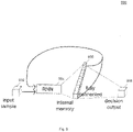
- Fig. 9 shows an illustration 900 of a neural network with an internal memory, which may be used as the machine learning method according to various embodiments.
- the neural network shown in Fig. 9 may be a RNN (recurrent neural network) 904.
- Variant of RNNs may include LSTMs (long short term memories) and GRUs (gated recurrent units).
- the RNN 904 may receive a single sample 904 at each time, and an internal memory 906, which may be connected to the RNN 904 as shown in Fig. 9 (or which may be included in the RNN 904), and which may be fully connected as a further input of the RNN 904 may be provided. (and the internal memory of the last step) for input.
- the output decision 908 may be based on the internal memory 906 (which may also be referred to as internal state).
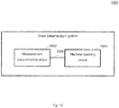
- Fig. 10 shows a state determination system 1000 according to various embodiments.
- the state determination system 1000 may include a measurement determination circuit 1002 and a machine learning circuit 1004.
- the measurement determination circuit 1002 may be configured to determine a plurality of load current measurements of an arrangement of electric and/or electronic components.
- the machine learning circuit 1004 may be configured to determine the state of the arrangement based on the plurality of load current measurements.
- the measurement determination circuit 1002 and the machine learning circuit 1004 may be coupled with each other, e.g. via an electrical connection 1006, such as e.g. a cable or a computer bus or via any other suitable electrical connection to exchange electrical signals.
- an electrical connection 1006 such as e.g. a cable or a computer bus or via any other suitable electrical connection to exchange electrical signals.
- a “circuit” may be understood as any kind of a logic implementing entity, which may be special purpose circuitry or a processor executing a program stored in a memory, firmware, or any combination thereof.
- Fig. 11 shows a computer system 1100 with a plurality of computer hardware components configured to carry out steps of a computer implemented method for determining a state of an arrangement of electric and/or electronic components according to various embodiments.
- the computer system 1100 may include a processor 1102, a memory 1104, and a non-transitory data storage 1106.
- a load current sensor 1108 may be provided as part of the computer system 1100 (like illustrated in Fig. 11 ), or may be provided external to the computer system 1100.
- the processor 1102 may carry out instructions provided in the memory 1104.
- the non-transitory data storage 1106 may store a computer program, including the instructions that may be transferred to the memory 1104 and then executed by the processor 1102.
- the load current sensor 1108 may be used for determining or measuring) a current (which may be referred to as load current), for example a current related to a power consumed by one or more load of the arrangement.
- the processor 1102, the memory 1104, and the non-transitory data storage 1106 may be coupled with each other, e.g. via an electrical connection 1110, such as e.g. a cable or a computer bus or via any other suitable electrical connection to exchange electrical signals.
- the load current sensor 1108 may be coupled to the computer system 1100, for example via an external interface, or may be provided as parts of the computer system (in other words: internal to the computer system, for example coupled via the electrical connection 1110).
- Coupled or “connection” are intended to include a direct “coupling” (for example via a physical link) or direct “connection” as well as an indirect “coupling” or indirect “connection” (for example via a logical link), respectively.
Landscapes
- Engineering & Computer Science (AREA)
- Physics & Mathematics (AREA)
- Theoretical Computer Science (AREA)
- General Physics & Mathematics (AREA)
- Data Mining & Analysis (AREA)
- Artificial Intelligence (AREA)
- Software Systems (AREA)
- Evolutionary Computation (AREA)
- General Engineering & Computer Science (AREA)
- Computing Systems (AREA)
- Life Sciences & Earth Sciences (AREA)
- Mathematical Physics (AREA)
- Computational Linguistics (AREA)
- General Health & Medical Sciences (AREA)
- Biophysics (AREA)
- Biomedical Technology (AREA)
- Health & Medical Sciences (AREA)
- Molecular Biology (AREA)
- Computer Vision & Pattern Recognition (AREA)
- Power Engineering (AREA)
- Evolutionary Biology (AREA)
- Bioinformatics & Computational Biology (AREA)
- Medical Informatics (AREA)
- Computer Hardware Design (AREA)
- Microelectronics & Electronic Packaging (AREA)
- Chemical & Material Sciences (AREA)
- Combustion & Propulsion (AREA)
- Bioinformatics & Cheminformatics (AREA)
- Remote Monitoring And Control Of Power-Distribution Networks (AREA)
- Charge And Discharge Circuits For Batteries Or The Like (AREA)
- Emergency Protection Circuit Devices (AREA)
Abstract
Description
- The present disclosure relates to methods and systems for determining a state of an arrangement of electric and/or electronic components.
- Input currents of different loads and consumers, for example within a vehicle, are commonly supplied by relays and melting fuses, which however provide a slow and error-prone way of cutting loads and consumers from a current source.
- Accordingly, there is a need to provide enhanced means to control loads and consumers.
- The present disclosure provides a computer implemented method, a computer system, a vehicle, a battery charger, and a non-transitory computer readable medium according to the independent claims. Embodiments are given in the subclaims, the description and the drawings.
- In one aspect, the present disclosure is directed at a computer implemented method for determining a state of an arrangement of electric and/or electronic components, the method comprising the following steps performed (in other words: carried out) by computer hardware components: determining a plurality of load current measurements of the arrangement; providing the plurality of load current measurements to a machine learning method; and determining the state of the arrangement based on the plurality of load current measurements using the machine learning method.
- It will be understood that the load current is a current, for example a current is related to power consumed by one or more loads.
- The method may provide a smart fuse technology for mainly automotive purpose using artificial neural networks. The method may improve and solve many problems of prior art techniques such as: being more focused on application peripherals and parameters of attached components like loads, wire harness and supply voltages; more flexible against environmental changes since there is no static threshold being compared to monitored current level; according to environmental changes (e.g. temperatures) the model can directly be exchanged by software; more complex current profile trends can be taken into account without loading processor CPU; and more detailed trend indications can be analyzed with smaller effort in the field application. Mainly decreased processor performance needed.
- According to another aspect, determining the state of the arrangement comprises classifying the state of the arrangement into one of a plurality of classes.
- According to another aspect, the classes comprise a class of overload state and a class of non-overload state. Thus, the method may be provided to provide input to an electronic fuse, for example a power switch, to determine overload situations, in which the switch shall disconnect the load from the supply.
- According to another aspect, the classes comprise a class of fully charged and a class of not fully charged, or the classes comprise a plurality of classes corresponding to pre-determined percentages of full charging (for example classes for 0%, 25,%, 50%, 75%, and 100% of full charging, or classes of 0%, 10%, 20%, 30%, 40%, 50%, 60%, 70%, 80%, 90%, and 100% of full charging). Thus, the method may be provided for controlling charging, for example charging of a battery, for example a battery of a vehicle.
- According to another aspect, the plurality of load current measurements comprises a plurality of series of load current measurements, each series comprising a pre-determined number of subsequent load current measurements. The pre-determined number of subsequent load current measurements may be provided subsequently in time. Each series may be referred to as a snapshot.
- According to another aspect, the plurality of series may overlap in time. This may ensure that each of the plurality of load current measurements are treated in the context of the neighboring load current measurements.
- According to another aspect, the machine learning method comprises a method using an artificial neural network. With the method, a load current profile classification with neural network implementation may be provided, for example for smart fusing. The smart fuse arrangement may be provided using a machine learning approach trained using an electronic load current profile classification system.
- According to another aspect, the artificial neural network comprises a convolutional neural network.
- According to another aspect, the convolutional neural network comprises a network with a 3x3 cascade.
- According to another aspect, the artificial neural network comprises a long short-term memory.
- In another aspect, the present disclosure is directed at a computer system, said computer system comprising a plurality of computer hardware components configured to carry out several or all steps of the computer implemented method described herein.
- The computer system may comprise a plurality of computer hardware components (for example a processor, for example processing unit or processing network, at least one memory, for example memory unit or memory network, and at least one non-transitory data storage). It will be understood that further computer hardware components may be provided and used for carrying out steps of the computer implemented method in the computer system. The non-transitory data storage and/or the memory unit may comprise a computer program for instructing the computer to perform several or all steps or aspects of the computer implemented method described herein, for example using the processing unit and the at least one memory unit.
- According to another aspect, the computer system further comprises a digital signal processor configured to carry out the machine learning method.
- In another aspect, the present disclosure is directed at a vehicle comprising the computer system described herein and a sensor configured to determine the plurality of load current measurements of the arrangement.
- In another aspect, the present disclosure is directed at a battery charger comprising the computer system as described herein and a sensor configured to determine the plurality of load current measurements of the arrangement. The battery charger may further include a voltage sensor configured to determine a voltage of the arrangement. The battery charger may further include a temperature r sensor configured to determine a temperature of the arrangement. The state of the arrangement may then be determined further based on the voltage and/or the temperature. The arrangement may be a battery.
- The battery charger may control a current provided to the battery, for example using a pulse width modulation (PWM) of a current.
- In another aspect, the present disclosure is directed at a non-transitory computer readable medium comprising instructions for carrying out several or all steps or aspects of the computer implemented method described herein. The computer readable medium may be configured as: an optical medium, such as a compact disc (CD) or a digital versatile disk (DVD); a magnetic medium, such as a hard disk drive (HDD); a solid state drive (SSD); a read only memory (ROM), such as a flash memory; or the like. Furthermore, the computer readable medium may be configured as a data storage that is accessible via a data connection, such as an internet connection. The computer readable medium may, for example, be an online data repository or a cloud storage.
- Various aspects may be applicable for replacing electronic relay and fusing systems, and may be applicable for power supplies on vehicle system level or ECU (electronic control unit) internally (for example for the power tree).
- Various aspects may provide a high performance smart fusing, and may provide an adaptable and intelligent switching and fusing which allows small margins for power tree and W/H (wiring harness).
- With various aspects, cost reduction for vehicle systems will be possible,
- The present disclosure is also directed at a computer program for instructing a computer to perform several or all steps or aspects of the computer implemented method described herein.
- Exemplary embodiments and functions of the present disclosure are described herein in conjunction with the following drawings, showing schematically:
- Fig. 1
- a block diagram illustrating an electronic load current profile classification system according to various embodiments;
- Fig. 2
- an illustration of overlap of load current measurements in various snapshots;
- Fig. 3
- an illustration of a physical measurement and logging procedure according to various embodiments;
- Fig. 4
- an illustration of how a machine learning model is trained;
- Fig. 5
- an illustration of 200 samples of load current;
- Fig. 6
- an illustration of two verification profiles for both triggering and non-triggering current profile;
- Fig. 7
- a flow diagram illustrating a method for determining a state of an arrangement of electric and/or electronic components according to various embodiments;
- Fig. 8
- an illustration of a cellular neural network, which may be used as the machine learning method according to various embodiments;
- Fig. 9
- an illustration of a neural network with an internal memory, which may be used as the machine learning method according to various embodiments;
- Fig. 10
- a state determination system according to various embodiments; and
- Fig. 11
- a computer system with a plurality of computer hardware components configured to carry out steps of a computer implemented method for determining a state of an arrangement of electric and/or electronic components according to various embodiments.
- Input currents of different loads and consumers within the vehicle are commonly supplied by relays and melting fuses since. According to various embodiments, electronic circuits may observe the load current and may detach the load from wiring harness of a vehicle in case of overcurrent detection.
- All formerly used methods have the disadvantage that either they are based on thermal heating due to occurred overcurrent (slow process and unreliable) or a simple threshold exceed is detected and the system decides to simply turn off the load, to faster protect the wiring harness. In reality, a lot current profile characteristics may occur which may be dependent on load type, attached wiring harness length, environmental temperature and vehicle supply voltage level and many more.
- According to various embodiments, an intelligent and adaptable way is provided to ensure highest load availability for increasing protection level of the wiring harness and to be flexible enough against environmental changes.
- Various embodiments may improve standard fusing devices, smart fusing devices and existing circuits for protecting the wiring harness and attached loads against overcurrents and even short circuits.
- Various embodiments may be used for systems and module features needed in future beside fusing strategies, where short reaction times and adaptability to changes of a physical value within a certain time (profiles) should be applied.
-
Fig. 1 shows a block diagram 100 illustrating an electronic load current profile classification system according to various embodiments, for example using circuit components and a heterogeneous microprocessor structure, including a neural network accelerator 112 (which may include a neural processing unit and/or a numeric processing unit and/or a DSP (digital signal processor), and which may provide profile classification). - Incoming samples of a load
current measurement 102 may be handled by an Analog-to-Digital-Converter (ADC)module 104. The samples may be taken in equal time intervals dt and may be handed over to a central processing unit 106 (which may be referred to as a processor). The samples may include integer values, which may be buffered into a random access memory (RAM)storage 110. According to various embodiments, the samples may be (directly) provided from theADC 106 to theRAM 110 by DMA 116 (direct memory access). TheRAM storage 110 may be configured as ringbuffer structures of several counts. Every filled buffer may contain a snapshot of the measured current profile. To ensure that all important parts of the profile are properly post-processed and classified, there may be overlapping parts between the several buffers, like illustrated inFig. 2 . For example, for realization of fast throughput and low CPU load, DMA may be used for ADC data exchange to RAM fetched by the NPU/DSP unit. -
Fig. 2 shows anillustration 200 of overlap of load current measurements in various snapshots. For example, a real (or actual)current profile 202 is shown, and threeprofile snapshots - Returning to
Fig. 1 , a neuralnetwork computing unit 112 may fetch the contents of the several ring buffers from theRAM 110, and may classify the contents using a pretrained CNN (for example a convolutional neural network or a cellular neural network))model 114. - The (artificial) neural network may be a CNN constellated as 3x3 cascade. Also, LSTM (long short-term memory) could be used, for example if there is a higher focus on time-based dependencies.
- The (artificial) neural network may receive a time series of measurement data. Alternatively, the (artificial) neural network may receive measurement data for each time individually, and may have an internal memory; for example, the (artificial) neural network may be a recurrent neural network (RNN).
- The
pretrained model 114 may be generated out of several tens and hundreds of measured load current profiles in laboratory test fields, for example generated with application specific wiring harness, supply parameters and load properties. - If the classification reflects a certain probability that the
pretrained CNN model 114 is overlapping with buffer contents, this result may be reported as positive detection to the processor CPU 106 (which may act as a safety controller). The method may then be receiving this signal and may decide how to react. For example, the absolute current level may additionally be checked, for example by a state machine. - The
pretrained model 114 may mainly be focused on certain trends that will probably lead to overcurrents caused by failures or even short circuits to realize wireguard system that is fast enough to protect the wiring harness before overheating. - Furthermore, a following state machine may be used for failure mitigation in case the
CNN accelerator 112 is signaling an overcurrent trend. - Based on the classification results, the CPU may control a
power switch 108, for example a power MOSFET (metal oxide semiconductor field-effect transistor) switch. - In the following, training of a network (for example neural network) according to various embodiments will be described.
- In a first step to generate a machine learning model, data from the field application may be taken. For this approach, the same components of the wiring system may be used and a continuous measurement may be realized to record all possible behaviors on the line.
-
Fig. 3 shows anillustration 300 of a physical measurement and logging procedure according to various embodiments. Acurrent measurement 302 may be provided to data logging 304, and based on the logged data, a database (for example including raw data) may be generated (306). -
Fig. 4 shows anillustration 400 of how a machine learning model (for example a neural network) is trained. At 402, a machine learning problem may be defined and a solution may be proposed. At 404, a data set may be constructed. At 40, raw data may be collected, feature and label sources may be identified, a sampling strategy may be selected, and the data may be split. At 408, data may be transformed. At 410, data may be explored and cleaned and feature engineering may be performed. At 412, the machine learning model may be trained. At 414, the (trained) machine learning model may be used to make predictions. -
Fig. 5 shows anillustration 500 of a plurality of samples of load current. The high peak current values should trigger the fuse function of the system. It can be seen that the current is shortly increased and lowers itself afterwards. It then reaches an average current which was slightly higher than in the beginning of the scenario. Those logged datasets are used to train a neural network in the next step. - Depending on the number of taken samples and the data length as well the complexity of the curve behaviours it has to be judged into which model the neural network has to be trained in. Mainly the decision of layer counts and the used activation functions have to be chosen right to generate a reproducible functionality of the network.
- In the following, an inference output of the used ML (machine learning) model will be described.
- In addition to the trained model, a verification script may be generated that binds in the machine learning model as .tflite file and executes it with an arbitrary test current profile. This approach may be seen as a kind of model validation, to see if the idea behind this concept works fine.
- One can then directly check the probability of the existence of a dangerous current profile, on which the fuse should trigger on.
-
Fig. 6 shows anillustration 600 of two verification profiles for both triggering and non-triggering current profile. Afirst profile 604 shows a profile sample on which the controller should enable the fusing mechanism: Detection probability was calculated with 95% by the trained model. Asecond profile 602 shows a profile sample on which the controller should not enable the fusing mechanism an current proceeds to flow: Detection probability was calculated with 5% by the trained model. - According to various embodiments, the model may be used on a microcontroller system. As soon as the model is trained and validated, it may be deployed on a microprocessor or even microcontroller system. In case a smaller controller should be used, tensorflow-lite micro libraries may be used, which may be focused on supporting those systems with smaller memory and computation capabilities.
- According to various embodiments, neural nets (neural networks) may be used for recognizing current profiles, to be prealarmed for possible faults on the supply system.
- The neural net may be trained with existing measurement samples and a model may be generated that knows that such profiles can exist in case a module changes its internal function (for example when the current increases shortly). It may be the case that the current level exceeds a specific limit of capabilities, e.g. wiring harness current load, but only for very short time.
- The model can be trained to be prealarmed if such increases are presen.t
- By this approach the limit exceed is tolerated and no overcurrent detection is generated.
- In case the same limit is exceeded with another characteristic like shorter or even longer current increase, the model and the microcontroller may be smart enough to detect it as unregularity and protect load as well as wiring harness by switching off the supply path.
-
Fig. 7 shows a flow diagram 700 illustrating a method for determining a state of an arrangement of electric and/or electronic components according to various embodiments. At 702, a plurality of load current measurements of the arrangement may be determined. At 704, the plurality of load current measurements may be provided to a machine learning method. At 706, the state of the arrangement may be determined based on the plurality of load current measurements using the machine learning method. - According to various embodiments, determining the state of the arrangement may include or may be classifying the state of the arrangement into one of a plurality of classes.
- According to various embodiments, the classes may include or may be a class of overload state and a class of non-overload state.
- According to various embodiments, the classes may include or may be a class of fully charged and a class of not fully charged.
- According to various embodiments, the plurality of load current measurements may include or may be a plurality of series of load current measurements, each series including a pre-determined number of subsequent load current measurements.
- According to various embodiments, the plurality of series may overlap in time.
- According to various embodiments, the machine learning method may include or may be a method using an artificial neural network.
- According to various embodiments, the artificial neural network may include or may be a convolutional neural network.
- According to various embodiments, the convolutional neural network may include or may be a network with a 3x3 cascade.
- According to various embodiments, the artificial neural network may include or may be a long short-term memory.
- Each of the
steps -
Fig. 8 shows anillustration 800 of a cellular neural network (CNN), which may be used as the machine learning method according to various embodiments. A time series 802 (in other words: data over a plurality of time points) may be received as an input, and may be provided as afirst layer 804. It can be seen that the information gradually moves from spatial (time domain) encoding (in layer 804) into an orthogonal feature dimension (layer 810, vialayers 806 and 808) before being combined into a (scalar)decision 812. -
Fig. 9 shows anillustration 900 of a neural network with an internal memory, which may be used as the machine learning method according to various embodiments. The neural network shown inFig. 9 may be a RNN (recurrent neural network) 904. Variant of RNNs may include LSTMs (long short term memories) and GRUs (gated recurrent units). TheRNN 904 may receive asingle sample 904 at each time, and aninternal memory 906, which may be connected to theRNN 904 as shown inFig. 9 (or which may be included in the RNN 904), and which may be fully connected as a further input of theRNN 904 may be provided. (and the internal memory of the last step) for input. Theoutput decision 908 may be based on the internal memory 906 (which may also be referred to as internal state). -
Fig. 10 shows astate determination system 1000 according to various embodiments. Thestate determination system 1000 may include ameasurement determination circuit 1002 and amachine learning circuit 1004. - The
measurement determination circuit 1002 may be configured to determine a plurality of load current measurements of an arrangement of electric and/or electronic components. - The
machine learning circuit 1004 may be configured to determine the state of the arrangement based on the plurality of load current measurements. - The
measurement determination circuit 1002 and themachine learning circuit 1004 may be coupled with each other, e.g. via anelectrical connection 1006, such as e.g. a cable or a computer bus or via any other suitable electrical connection to exchange electrical signals. - A "circuit" may be understood as any kind of a logic implementing entity, which may be special purpose circuitry or a processor executing a program stored in a memory, firmware, or any combination thereof.
-
Fig. 11 shows acomputer system 1100 with a plurality of computer hardware components configured to carry out steps of a computer implemented method for determining a state of an arrangement of electric and/or electronic components according to various embodiments. Thecomputer system 1100 may include aprocessor 1102, amemory 1104, and anon-transitory data storage 1106. A loadcurrent sensor 1108 may be provided as part of the computer system 1100 (like illustrated inFig. 11 ), or may be provided external to thecomputer system 1100. - The
processor 1102 may carry out instructions provided in thememory 1104. Thenon-transitory data storage 1106 may store a computer program, including the instructions that may be transferred to thememory 1104 and then executed by theprocessor 1102. The loadcurrent sensor 1108 may be used for determining or measuring) a current (which may be referred to as load current), for example a current related to a power consumed by one or more load of the arrangement. - The
processor 1102, thememory 1104, and thenon-transitory data storage 1106 may be coupled with each other, e.g. via anelectrical connection 1110, such as e.g. a cable or a computer bus or via any other suitable electrical connection to exchange electrical signals. The loadcurrent sensor 1108 may be coupled to thecomputer system 1100, for example via an external interface, or may be provided as parts of the computer system (in other words: internal to the computer system, for example coupled via the electrical connection 1110). - The terms "coupling" or "connection" are intended to include a direct "coupling" (for example via a physical link) or direct "connection" as well as an indirect "coupling" or indirect "connection" (for example via a logical link), respectively.
- It will be understood that what has been described for one of the methods above may analogously hold true for the
state determination system 1000 and/or for thecomputer system 1100. -
- 100
- block diagram illustrating an electronic load current profile classification system according to various embodiments
- 102
- load current measurement
- 104
- ADC module
- 106
- central processing unit
- 108
- power switch
- 110
- storage
- 112
- neural network accelerator
- 114
- CNN model
- 116
- DMA
- 200
- illustration of overlap of load current measurements in various snapshots
- 202
- real current profile
- 204
- profile snapshot
- 206
- profile snapshot
- 208
- profile snapshot
- 300
- illustration of a physical measurement and logging procedure according to various embodiments
- 302
- current measurement
- 304
- data logging
- 306
- generation of database
- 400
- illustration of how a machine learning model is trained
- 402
- define machine learning problem and propose solution
- 404
- construct data set
- 406
- collect raw data et al
- 408
- transform data
- 410
- explore and clean data and feature engineering
- 412
- train machine learning model
- 414
- use machine learning model to make predictions
- 500
- illustration of 200 samples of load current
- 600
- illustration of two verification profiles for both triggering and non-triggering current profile
- 602
- second profile
- 604
- first profile
- 700
- flow diagram illustrating a method for determining a state of an arrangement of electric and/or electronic components according to various embodiments
- 702
- step of determining a plurality of load current measurements of the arrangement
- 704
- step of providing the plurality of load current measurements to a machine learning method
- 706
- step of determining the state of the arrangement based on the plurality of load current measurements using the machine learning method
- 800
- illustration of a cellular neural network, which may be used as the machine learning method according to various embodiments
- 802
- time series
- 804
- layer
- 806
- layer
- 808
- layer
- 810
- layer
- 812
- decision
- 900
- illustration of a neural network with an internal memory, which may be used as the machine learning method according to various embodiments
- 902
- input sample
- 904
- recurrent neural network
- 906
- internal memory
- 908
- decision output
- 1000
- state determination system
- 1002
- measurement determination circuit
- 1004
- machine learning circuit
- 1006
- connection
- 1100
- computer system according to various embodiments
- 1102
- processor
- 1104
- memory
- 1106
- non-transitory data storage
- 1108
- load current sensor
- 1110
- connection
Claims (15)
- Computer implemented method for determining a state of an arrangement of electric and/or electronic components,
the method comprising the following steps carried out by computer hardware components:- determining (702) a plurality of load current measurements of the arrangement;- providing (704) the plurality of load current measurements to a machine learning method; and- determining (706) the state of the arrangement based on the plurality of load current measurements using the machine learning method. - The computer implemented method of claim 1,
wherein determining the state of the arrangement comprises classifying the state of the arrangement into one of a plurality of classes. - The computer implemented method of claim 2,
wherein the classes comprise a class of overload state and a class of non-overload state. - The computer implemented method of claim 2,
wherein the classes comprise a class of fully charged and a class of not fully charged; or.
wherein the classes comprise a plurality of classes corresponding to pre-determined percentages of full charging. - The computer implemented method of at least one of claims 1 to 4,
wherein the plurality of load current measurements comprises a plurality of series of load current measurements, each series comprising a pre-determined number of subsequent load current measurements. - The computer implemented method of claim 5,
wherein the plurality of series overlap in time. - The computer implemented method of at least one of claims 1 to 6,
wherein the machine learning method comprises a method using an artificial neural network. - The computer implemented method of claim 7,
wherein the artificial neural network comprises a convolutional neural network. - The computer implemented method of claim 8,
wherein the convolutional neural network comprises a network with a 3x3 cascade. - The computer implemented method of at least one of claims 7 to 9,
wherein the artificial neural network comprises a long short-term memory. - Computer system (1100), the computer system (1100) being configured to carry out the computer implemented method of at least one of claims 1 to 10.
- The computer system (1100) of claim 11, further comprising:
a digital signal processor configured to carry out the machine learning method. - Vehicle comprising the computer system (1100) of claim 11 and a sensor configured to determine the plurality of load current measurements of the arrangement.
- Battery charger comprising the computer system (1100) of claim 11 and a sensor configured to determine the plurality of load current measurements of the arrangement.
- Non-transitory computer readable medium comprising instructions for carrying out the computer implemented method of at least one of claims 1 to 10.
Priority Applications (3)
| Application Number | Priority Date | Filing Date | Title |
|---|---|---|---|
| EP20205139.7A EP3992643B1 (en) | 2020-11-02 | 2020-11-02 | Methods and systems for determining a state of an arrangement of electric and/or electronic components |
| US17/516,548 US20220137107A1 (en) | 2020-11-02 | 2021-11-01 | Methods and Systems for Determining a State of an Arrangement of Electric and/or Electronic Components |
| CN202111280971.2A CN114528901A (en) | 2020-11-02 | 2021-11-01 | Method and system for determining the state of a structure of an electrical and/or electronic component |
Applications Claiming Priority (1)
| Application Number | Priority Date | Filing Date | Title |
|---|---|---|---|
| EP20205139.7A EP3992643B1 (en) | 2020-11-02 | 2020-11-02 | Methods and systems for determining a state of an arrangement of electric and/or electronic components |
Publications (2)
| Publication Number | Publication Date |
|---|---|
| EP3992643A1 true EP3992643A1 (en) | 2022-05-04 |
| EP3992643B1 EP3992643B1 (en) | 2024-09-25 |
Family
ID=73043158
Family Applications (1)
| Application Number | Title | Priority Date | Filing Date |
|---|---|---|---|
| EP20205139.7A Active EP3992643B1 (en) | 2020-11-02 | 2020-11-02 | Methods and systems for determining a state of an arrangement of electric and/or electronic components |
Country Status (3)
| Country | Link |
|---|---|
| US (1) | US20220137107A1 (en) |
| EP (1) | EP3992643B1 (en) |
| CN (1) | CN114528901A (en) |
Citations (2)
| Publication number | Priority date | Publication date | Assignee | Title |
|---|---|---|---|---|
| CN108535566A (en) * | 2016-04-08 | 2018-09-14 | 湖南工业大学 | Electric appliance sorter |
| US20200081070A1 (en) * | 2017-11-20 | 2020-03-12 | The Trustees Of Columbia University In The City Of New York | Neural-network state-of-charge and state of health estimation |
Family Cites Families (17)
| Publication number | Priority date | Publication date | Assignee | Title |
|---|---|---|---|---|
| CN102419422B (en) * | 2011-08-19 | 2014-03-12 | 奇瑞汽车股份有限公司 | Method for estimating stage of charge (SOC) |
| KR102256301B1 (en) * | 2015-01-30 | 2021-05-26 | 삼성에스디아이 주식회사 | Charging and Discharging Control System and Method for Battery |
| US10186890B2 (en) * | 2015-06-16 | 2019-01-22 | Huazhen Fang | System and method for battery charging |
| US10879805B2 (en) * | 2015-09-22 | 2020-12-29 | Infineon Technologies Austria Ag | System and method for a switched-mode power supply having a transformer with a plurality of primary windings |
| CN106067758A (en) * | 2016-05-25 | 2016-11-02 | 河海大学常州校区 | Photovoltaic generating system method for diagnosing faults based on parameter identification and system |
| US10209314B2 (en) * | 2016-11-21 | 2019-02-19 | Battelle Energy Alliance, Llc | Systems and methods for estimation and prediction of battery health and performance |
| US10599205B2 (en) * | 2017-09-18 | 2020-03-24 | Verizon Patent And Licensing Inc. | Methods and systems for managing machine learning involving mobile devices |
| US11520395B2 (en) * | 2017-12-19 | 2022-12-06 | Intel Corporation | Integrated circuit power systems with machine learning capabilities |
| US11131713B2 (en) * | 2018-02-21 | 2021-09-28 | Nec Corporation | Deep learning approach for battery aging model |
| GB201819717D0 (en) * | 2018-12-03 | 2019-01-16 | Univ Oxford Innovation Ltd | Method and system for monitoring a remote system |
| CN109870654B (en) * | 2019-02-02 | 2021-07-13 | 福州大学 | Online Dynamic Estimation Method of Battery Capacity Based on Shock Load Response Characteristics |
| US10641836B1 (en) * | 2019-02-06 | 2020-05-05 | Chongqing Jinkang New Energy Automobile Co., Ltd. | Battery state of health estimation using open circuit voltage slope |
| CN109828218B (en) * | 2019-02-25 | 2020-06-09 | 清华大学 | Method for acquiring dynamic electrochemical impedance spectrum of battery |
| KR102753151B1 (en) * | 2019-08-05 | 2025-01-10 | 엘지전자 주식회사 | Artificial intelligent refrigerator |
| US20210049480A1 (en) * | 2019-08-12 | 2021-02-18 | Micron Technology, Inc. | Predictive maintenance of automotive battery |
| EP3812783B1 (en) * | 2019-10-23 | 2024-11-27 | Novum engineerING GmbH | Estimating a battery state from electrical impedance measurements using convolutional neural network means |
| CN111762096A (en) * | 2020-06-27 | 2020-10-13 | 王亚鹏 | New energy automobile safety early warning method and system based on artificial intelligence |
-
2020
- 2020-11-02 EP EP20205139.7A patent/EP3992643B1/en active Active
-
2021
- 2021-11-01 US US17/516,548 patent/US20220137107A1/en not_active Abandoned
- 2021-11-01 CN CN202111280971.2A patent/CN114528901A/en active Pending
Patent Citations (2)
| Publication number | Priority date | Publication date | Assignee | Title |
|---|---|---|---|---|
| CN108535566A (en) * | 2016-04-08 | 2018-09-14 | 湖南工业大学 | Electric appliance sorter |
| US20200081070A1 (en) * | 2017-11-20 | 2020-03-12 | The Trustees Of Columbia University In The City Of New York | Neural-network state-of-charge and state of health estimation |
Non-Patent Citations (2)
| Title |
|---|
| NANDA SANTOSH KUMAR ET AL: "Virtual instrument based fault classification in power transformers using artificial neural networks", 2013 IEEE 1ST INTERNATIONAL CONFERENCE ON CONDITION ASSESSMENT TECHNIQUES IN ELECTRICAL SYSTEMS (CATCON), IEEE, 6 December 2013 (2013-12-06), pages 169 - 173, XP032565072, DOI: 10.1109/CATCON.2013.6737492 * |
| RASHID ROZEHA A ET AL: "Machine Learning for Smart Energy Monitoring of Home Appliances Using IoT", 2019 ELEVENTH INTERNATIONAL CONFERENCE ON UBIQUITOUS AND FUTURE NETWORKS (ICUFN), IEEE, 2 July 2019 (2019-07-02), pages 66 - 71, XP033600747, DOI: 10.1109/ICUFN.2019.8806026 * |
Also Published As
| Publication number | Publication date |
|---|---|
| US20220137107A1 (en) | 2022-05-05 |
| EP3992643B1 (en) | 2024-09-25 |
| CN114528901A (en) | 2022-05-24 |
Similar Documents
| Publication | Publication Date | Title |
|---|---|---|
| CN111587378B (en) | Integrated circuit margin measurement and failure prediction apparatus | |
| CN109591626B (en) | Protection method, system, device and storage medium for precharging resistor | |
| EP2362408B1 (en) | Safety switching device with universal signal input | |
| Razi-Kazemi | Applicability of auxiliary contacts in circuit breaker online condition assessment | |
| US20150369865A1 (en) | Detection of fault injection attacks using high-fanout networks | |
| Letor et al. | Smart Power devices and new electronic fuses compliant with new E/E architecture for autonomous driving | |
| US10552278B2 (en) | Non-destructive analysis to determine use history of processor | |
| US20250004433A1 (en) | Method and system for generating a decision logic and electric power system | |
| CN118707407B (en) | Capacitive load test system, capacitive load test method, electronic device, storage medium and capacitive load test product | |
| US20130314836A1 (en) | Transistor Overcurrent Detection | |
| CN119644976A (en) | Aircraft fault early warning method and system based on flight data | |
| Schwimmbeck et al. | Evaluation of short-circuits in automotive power nets with different wire inductances | |
| EP3992643B1 (en) | Methods and systems for determining a state of an arrangement of electric and/or electronic components | |
| US10097172B2 (en) | Method for protecting a controllable semiconductor switch from overload and short-circuiting in a load circuit | |
| US11188683B2 (en) | Hardware intrusion detection system | |
| CN115140075B (en) | Quantitative evaluation method, device, equipment and medium for safety of expected functions of vehicle | |
| US11637422B2 (en) | Electronic device | |
| CN111465867B (en) | Method for testing output stages for actuating loads | |
| Ashok et al. | Fault detection and classification of multi-location and evolving faults in double-circuit transmission line using ANN | |
| US11996527B2 (en) | Technique for monitoring a battery cell | |
| CN114425787B (en) | Control method, device, server and storage medium for robot automatic testing | |
| Odabaşı et al. | Real-time detection of thermal propagation in batteries using univariate control charts | |
| US20250307701A1 (en) | Methods and apparatus to detect an electrical arc using machine learning | |
| CN117457583B (en) | Microparticle device, chip, electronic equipment, chip protection method, device and medium | |
| CN114678839B (en) | Improved desaturation protection circuit, design method and application for SiC MOSFET |
Legal Events
| Date | Code | Title | Description |
|---|---|---|---|
| PUAI | Public reference made under article 153(3) epc to a published international application that has entered the european phase |
Free format text: ORIGINAL CODE: 0009012 |
|
| STAA | Information on the status of an ep patent application or granted ep patent |
Free format text: STATUS: THE APPLICATION HAS BEEN PUBLISHED |
|
| AK | Designated contracting states |
Kind code of ref document: A1 Designated state(s): AL AT BE BG CH CY CZ DE DK EE ES FI FR GB GR HR HU IE IS IT LI LT LU LV MC MK MT NL NO PL PT RO RS SE SI SK SM TR |
|
| STAA | Information on the status of an ep patent application or granted ep patent |
Free format text: STATUS: REQUEST FOR EXAMINATION WAS MADE |
|
| 17P | Request for examination filed |
Effective date: 20221103 |
|
| RBV | Designated contracting states (corrected) |
Designated state(s): AL AT BE BG CH CY CZ DE DK EE ES FI FR GB GR HR HU IE IS IT LI LT LU LV MC MK MT NL NO PL PT RO RS SE SI SK SM TR |
|
| RAP3 | Party data changed (applicant data changed or rights of an application transferred) |
Owner name: APTIV TECHNOLOGIES LIMITED |
|
| GRAP | Despatch of communication of intention to grant a patent |
Free format text: ORIGINAL CODE: EPIDOSNIGR1 |
|
| STAA | Information on the status of an ep patent application or granted ep patent |
Free format text: STATUS: GRANT OF PATENT IS INTENDED |
|
| RAP1 | Party data changed (applicant data changed or rights of an application transferred) |
Owner name: APTIV TECHNOLOGIES AG |
|
| RIC1 | Information provided on ipc code assigned before grant |
Ipc: G06N 3/045 20230101ALI20240405BHEP Ipc: G06N 3/044 20230101ALI20240405BHEP Ipc: G06N 3/08 20060101ALI20240405BHEP Ipc: G06N 3/04 20060101ALI20240405BHEP Ipc: G01R 31/00 20060101AFI20240405BHEP |
|
| INTG | Intention to grant announced |
Effective date: 20240426 |
|
| GRAS | Grant fee paid |
Free format text: ORIGINAL CODE: EPIDOSNIGR3 |
|
| GRAA | (expected) grant |
Free format text: ORIGINAL CODE: 0009210 |
|
| STAA | Information on the status of an ep patent application or granted ep patent |
Free format text: STATUS: THE PATENT HAS BEEN GRANTED |
|
| P01 | Opt-out of the competence of the unified patent court (upc) registered |
Free format text: CASE NUMBER: APP_44853/2024 Effective date: 20240801 |
|
| AK | Designated contracting states |
Kind code of ref document: B1 Designated state(s): AL AT BE BG CH CY CZ DE DK EE ES FI FR GB GR HR HU IE IS IT LI LT LU LV MC MK MT NL NO PL PT RO RS SE SI SK SM TR |
|
| RAP3 | Party data changed (applicant data changed or rights of an application transferred) |
Owner name: APTIV TECHNOLOGIES AG |
|
| REG | Reference to a national code |
Ref country code: GB Ref legal event code: FG4D |
|
| REG | Reference to a national code |
Ref country code: CH Ref legal event code: EP |
|
| REG | Reference to a national code |
Ref country code: DE Ref legal event code: R096 Ref document number: 602020038224 Country of ref document: DE |
|
| REG | Reference to a national code |
Ref country code: IE Ref legal event code: FG4D |
|
| PGFP | Annual fee paid to national office [announced via postgrant information from national office to epo] |
Ref country code: DE Payment date: 20241016 Year of fee payment: 5 |
|
| REG | Reference to a national code |
Ref country code: LT Ref legal event code: MG9D |
|
| PG25 | Lapsed in a contracting state [announced via postgrant information from national office to epo] |
Ref country code: NO Free format text: LAPSE BECAUSE OF FAILURE TO SUBMIT A TRANSLATION OF THE DESCRIPTION OR TO PAY THE FEE WITHIN THE PRESCRIBED TIME-LIMIT Effective date: 20241225 |
|
| PG25 | Lapsed in a contracting state [announced via postgrant information from national office to epo] |
Ref country code: GR Free format text: LAPSE BECAUSE OF FAILURE TO SUBMIT A TRANSLATION OF THE DESCRIPTION OR TO PAY THE FEE WITHIN THE PRESCRIBED TIME-LIMIT Effective date: 20241226 Ref country code: FI Free format text: LAPSE BECAUSE OF FAILURE TO SUBMIT A TRANSLATION OF THE DESCRIPTION OR TO PAY THE FEE WITHIN THE PRESCRIBED TIME-LIMIT Effective date: 20240925 |
|
| PGFP | Annual fee paid to national office [announced via postgrant information from national office to epo] |
Ref country code: GB Payment date: 20241009 Year of fee payment: 5 |
|
| PG25 | Lapsed in a contracting state [announced via postgrant information from national office to epo] |
Ref country code: BG Free format text: LAPSE BECAUSE OF FAILURE TO SUBMIT A TRANSLATION OF THE DESCRIPTION OR TO PAY THE FEE WITHIN THE PRESCRIBED TIME-LIMIT Effective date: 20240925 |
|
| PG25 | Lapsed in a contracting state [announced via postgrant information from national office to epo] |
Ref country code: LV Free format text: LAPSE BECAUSE OF FAILURE TO SUBMIT A TRANSLATION OF THE DESCRIPTION OR TO PAY THE FEE WITHIN THE PRESCRIBED TIME-LIMIT Effective date: 20240925 |
|
| PGFP | Annual fee paid to national office [announced via postgrant information from national office to epo] |
Ref country code: FR Payment date: 20241025 Year of fee payment: 5 |
|
| PG25 | Lapsed in a contracting state [announced via postgrant information from national office to epo] |
Ref country code: RS Free format text: LAPSE BECAUSE OF FAILURE TO SUBMIT A TRANSLATION OF THE DESCRIPTION OR TO PAY THE FEE WITHIN THE PRESCRIBED TIME-LIMIT Effective date: 20241225 |
|
| REG | Reference to a national code |
Ref country code: NL Ref legal event code: MP Effective date: 20240925 |
|
| PG25 | Lapsed in a contracting state [announced via postgrant information from national office to epo] |
Ref country code: RS Free format text: LAPSE BECAUSE OF FAILURE TO SUBMIT A TRANSLATION OF THE DESCRIPTION OR TO PAY THE FEE WITHIN THE PRESCRIBED TIME-LIMIT Effective date: 20241225 Ref country code: NO Free format text: LAPSE BECAUSE OF FAILURE TO SUBMIT A TRANSLATION OF THE DESCRIPTION OR TO PAY THE FEE WITHIN THE PRESCRIBED TIME-LIMIT Effective date: 20241225 Ref country code: LV Free format text: LAPSE BECAUSE OF FAILURE TO SUBMIT A TRANSLATION OF THE DESCRIPTION OR TO PAY THE FEE WITHIN THE PRESCRIBED TIME-LIMIT Effective date: 20240925 Ref country code: GR Free format text: LAPSE BECAUSE OF FAILURE TO SUBMIT A TRANSLATION OF THE DESCRIPTION OR TO PAY THE FEE WITHIN THE PRESCRIBED TIME-LIMIT Effective date: 20241226 Ref country code: FI Free format text: LAPSE BECAUSE OF FAILURE TO SUBMIT A TRANSLATION OF THE DESCRIPTION OR TO PAY THE FEE WITHIN THE PRESCRIBED TIME-LIMIT Effective date: 20240925 Ref country code: BG Free format text: LAPSE BECAUSE OF FAILURE TO SUBMIT A TRANSLATION OF THE DESCRIPTION OR TO PAY THE FEE WITHIN THE PRESCRIBED TIME-LIMIT Effective date: 20240925 |
|
| REG | Reference to a national code |
Ref country code: AT Ref legal event code: MK05 Ref document number: 1727059 Country of ref document: AT Kind code of ref document: T Effective date: 20240925 |
|
| PG25 | Lapsed in a contracting state [announced via postgrant information from national office to epo] |
Ref country code: NL Free format text: LAPSE BECAUSE OF FAILURE TO SUBMIT A TRANSLATION OF THE DESCRIPTION OR TO PAY THE FEE WITHIN THE PRESCRIBED TIME-LIMIT Effective date: 20240925 |
|
| PG25 | Lapsed in a contracting state [announced via postgrant information from national office to epo] |
Ref country code: IS Free format text: LAPSE BECAUSE OF FAILURE TO SUBMIT A TRANSLATION OF THE DESCRIPTION OR TO PAY THE FEE WITHIN THE PRESCRIBED TIME-LIMIT Effective date: 20250125 Ref country code: PT Free format text: LAPSE BECAUSE OF FAILURE TO SUBMIT A TRANSLATION OF THE DESCRIPTION OR TO PAY THE FEE WITHIN THE PRESCRIBED TIME-LIMIT Effective date: 20250127 |
|
| PG25 | Lapsed in a contracting state [announced via postgrant information from national office to epo] |
Ref country code: RO Free format text: LAPSE BECAUSE OF FAILURE TO SUBMIT A TRANSLATION OF THE DESCRIPTION OR TO PAY THE FEE WITHIN THE PRESCRIBED TIME-LIMIT Effective date: 20240925 Ref country code: SM Free format text: LAPSE BECAUSE OF FAILURE TO SUBMIT A TRANSLATION OF THE DESCRIPTION OR TO PAY THE FEE WITHIN THE PRESCRIBED TIME-LIMIT Effective date: 20240925 |
|
| PG25 | Lapsed in a contracting state [announced via postgrant information from national office to epo] |
Ref country code: ES Free format text: LAPSE BECAUSE OF FAILURE TO SUBMIT A TRANSLATION OF THE DESCRIPTION OR TO PAY THE FEE WITHIN THE PRESCRIBED TIME-LIMIT Effective date: 20240925 |
|
| PG25 | Lapsed in a contracting state [announced via postgrant information from national office to epo] |
Ref country code: EE Free format text: LAPSE BECAUSE OF FAILURE TO SUBMIT A TRANSLATION OF THE DESCRIPTION OR TO PAY THE FEE WITHIN THE PRESCRIBED TIME-LIMIT Effective date: 20240925 Ref country code: AT Free format text: LAPSE BECAUSE OF FAILURE TO SUBMIT A TRANSLATION OF THE DESCRIPTION OR TO PAY THE FEE WITHIN THE PRESCRIBED TIME-LIMIT Effective date: 20240925 |
|
| PG25 | Lapsed in a contracting state [announced via postgrant information from national office to epo] |
Ref country code: CZ Free format text: LAPSE BECAUSE OF FAILURE TO SUBMIT A TRANSLATION OF THE DESCRIPTION OR TO PAY THE FEE WITHIN THE PRESCRIBED TIME-LIMIT Effective date: 20240925 Ref country code: PL Free format text: LAPSE BECAUSE OF FAILURE TO SUBMIT A TRANSLATION OF THE DESCRIPTION OR TO PAY THE FEE WITHIN THE PRESCRIBED TIME-LIMIT Effective date: 20240925 |
|
| PG25 | Lapsed in a contracting state [announced via postgrant information from national office to epo] |
Ref country code: SK Free format text: LAPSE BECAUSE OF FAILURE TO SUBMIT A TRANSLATION OF THE DESCRIPTION OR TO PAY THE FEE WITHIN THE PRESCRIBED TIME-LIMIT Effective date: 20240925 Ref country code: IT Free format text: LAPSE BECAUSE OF FAILURE TO SUBMIT A TRANSLATION OF THE DESCRIPTION OR TO PAY THE FEE WITHIN THE PRESCRIBED TIME-LIMIT Effective date: 20240925 |
|
| REG | Reference to a national code |
Ref country code: DE Ref legal event code: R097 Ref document number: 602020038224 Country of ref document: DE |
|
| REG | Reference to a national code |
Ref country code: CH Ref legal event code: PL |
|
| PG25 | Lapsed in a contracting state [announced via postgrant information from national office to epo] |
Ref country code: MC Free format text: LAPSE BECAUSE OF FAILURE TO SUBMIT A TRANSLATION OF THE DESCRIPTION OR TO PAY THE FEE WITHIN THE PRESCRIBED TIME-LIMIT Effective date: 20240925 |
|
| PG25 | Lapsed in a contracting state [announced via postgrant information from national office to epo] |
Ref country code: DK Free format text: LAPSE BECAUSE OF FAILURE TO SUBMIT A TRANSLATION OF THE DESCRIPTION OR TO PAY THE FEE WITHIN THE PRESCRIBED TIME-LIMIT Effective date: 20240925 |
|
| PG25 | Lapsed in a contracting state [announced via postgrant information from national office to epo] |
Ref country code: LU Free format text: LAPSE BECAUSE OF NON-PAYMENT OF DUE FEES Effective date: 20241102 |
|
| REG | Reference to a national code |
Ref country code: CH Ref legal event code: PL |
|
| PG25 | Lapsed in a contracting state [announced via postgrant information from national office to epo] |
Ref country code: CH Free format text: LAPSE BECAUSE OF NON-PAYMENT OF DUE FEES Effective date: 20241130 |
|
| PLBE | No opposition filed within time limit |
Free format text: ORIGINAL CODE: 0009261 |
|
| STAA | Information on the status of an ep patent application or granted ep patent |
Free format text: STATUS: NO OPPOSITION FILED WITHIN TIME LIMIT |
|
| REG | Reference to a national code |
Ref country code: BE Ref legal event code: MM Effective date: 20241130 |
|
| 26N | No opposition filed |
Effective date: 20250626 |
|
| PG25 | Lapsed in a contracting state [announced via postgrant information from national office to epo] |
Ref country code: SE Free format text: LAPSE BECAUSE OF FAILURE TO SUBMIT A TRANSLATION OF THE DESCRIPTION OR TO PAY THE FEE WITHIN THE PRESCRIBED TIME-LIMIT Effective date: 20240925 |
|
| PG25 | Lapsed in a contracting state [announced via postgrant information from national office to epo] |
Ref country code: BE Free format text: LAPSE BECAUSE OF NON-PAYMENT OF DUE FEES Effective date: 20241130 |
|
| PG25 | Lapsed in a contracting state [announced via postgrant information from national office to epo] |
Ref country code: IE Free format text: LAPSE BECAUSE OF NON-PAYMENT OF DUE FEES Effective date: 20241102 |
|
| PG25 | Lapsed in a contracting state [announced via postgrant information from national office to epo] |
Ref country code: HR Free format text: LAPSE BECAUSE OF FAILURE TO SUBMIT A TRANSLATION OF THE DESCRIPTION OR TO PAY THE FEE WITHIN THE PRESCRIBED TIME-LIMIT Effective date: 20240925 |
|
| PG25 | Lapsed in a contracting state [announced via postgrant information from national office to epo] |
Ref country code: HU Free format text: LAPSE BECAUSE OF FAILURE TO SUBMIT A TRANSLATION OF THE DESCRIPTION OR TO PAY THE FEE WITHIN THE PRESCRIBED TIME-LIMIT; INVALID AB INITIO Effective date: 20201102 |
|
| PG25 | Lapsed in a contracting state [announced via postgrant information from national office to epo] |
Ref country code: CY Free format text: LAPSE BECAUSE OF FAILURE TO SUBMIT A TRANSLATION OF THE DESCRIPTION OR TO PAY THE FEE WITHIN THE PRESCRIBED TIME-LIMIT; INVALID AB INITIO Effective date: 20201102 |