EP3992554B1 - Door body for refrigerator and assembly method therefor - Google Patents
Door body for refrigerator and assembly method therefor Download PDFInfo
- Publication number
- EP3992554B1 EP3992554B1 EP20849480.7A EP20849480A EP3992554B1 EP 3992554 B1 EP3992554 B1 EP 3992554B1 EP 20849480 A EP20849480 A EP 20849480A EP 3992554 B1 EP3992554 B1 EP 3992554B1
- Authority
- EP
- European Patent Office
- Prior art keywords
- bracket
- door
- trim strip
- door lining
- refrigerator
- Prior art date
- Legal status (The legal status is an assumption and is not a legal conclusion. Google has not performed a legal analysis and makes no representation as to the accuracy of the status listed.)
- Active
Links
Images




Classifications
-
- F—MECHANICAL ENGINEERING; LIGHTING; HEATING; WEAPONS; BLASTING
- F25—REFRIGERATION OR COOLING; COMBINED HEATING AND REFRIGERATION SYSTEMS; HEAT PUMP SYSTEMS; MANUFACTURE OR STORAGE OF ICE; LIQUEFACTION SOLIDIFICATION OF GASES
- F25D—REFRIGERATORS; COLD ROOMS; ICE-BOXES; COOLING OR FREEZING APPARATUS NOT OTHERWISE PROVIDED FOR
- F25D23/00—General constructional features
- F25D23/02—Doors; Covers
- F25D23/028—Details
-
- F—MECHANICAL ENGINEERING; LIGHTING; HEATING; WEAPONS; BLASTING
- F25—REFRIGERATION OR COOLING; COMBINED HEATING AND REFRIGERATION SYSTEMS; HEAT PUMP SYSTEMS; MANUFACTURE OR STORAGE OF ICE; LIQUEFACTION SOLIDIFICATION OF GASES
- F25D—REFRIGERATORS; COLD ROOMS; ICE-BOXES; COOLING OR FREEZING APPARATUS NOT OTHERWISE PROVIDED FOR
- F25D29/00—Arrangement or mounting of control or safety devices
- F25D29/005—Mounting of control devices
-
- F—MECHANICAL ENGINEERING; LIGHTING; HEATING; WEAPONS; BLASTING
- F25—REFRIGERATION OR COOLING; COMBINED HEATING AND REFRIGERATION SYSTEMS; HEAT PUMP SYSTEMS; MANUFACTURE OR STORAGE OF ICE; LIQUEFACTION SOLIDIFICATION OF GASES
- F25D—REFRIGERATORS; COLD ROOMS; ICE-BOXES; COOLING OR FREEZING APPARATUS NOT OTHERWISE PROVIDED FOR
- F25D2323/00—General constructional features not provided for in other groups of this subclass
- F25D2323/02—Details of doors or covers not otherwise covered
-
- F—MECHANICAL ENGINEERING; LIGHTING; HEATING; WEAPONS; BLASTING
- F25—REFRIGERATION OR COOLING; COMBINED HEATING AND REFRIGERATION SYSTEMS; HEAT PUMP SYSTEMS; MANUFACTURE OR STORAGE OF ICE; LIQUEFACTION SOLIDIFICATION OF GASES
- F25D—REFRIGERATORS; COLD ROOMS; ICE-BOXES; COOLING OR FREEZING APPARATUS NOT OTHERWISE PROVIDED FOR
- F25D2400/00—General features of, or devices for refrigerators, cold rooms, ice-boxes, or for cooling or freezing apparatus not covered by any other subclass
- F25D2400/18—Aesthetic features
-
- F—MECHANICAL ENGINEERING; LIGHTING; HEATING; WEAPONS; BLASTING
- F25—REFRIGERATION OR COOLING; COMBINED HEATING AND REFRIGERATION SYSTEMS; HEAT PUMP SYSTEMS; MANUFACTURE OR STORAGE OF ICE; LIQUEFACTION SOLIDIFICATION OF GASES
- F25D—REFRIGERATORS; COLD ROOMS; ICE-BOXES; COOLING OR FREEZING APPARATUS NOT OTHERWISE PROVIDED FOR
- F25D2400/00—General features of, or devices for refrigerators, cold rooms, ice-boxes, or for cooling or freezing apparatus not covered by any other subclass
- F25D2400/36—Visual displays
Definitions
- the present invention relates to the technical field of refrigerating and freezing devices, and in particular to a door of a refrigerator and an assembly method thereof.
- a display screen can only be attached to flat or curved glass.
- a border with a glue distance of at least 20 mm needs to be reserved, the display range of the left and right sides of the existing glass door is limited, and large-screen display cannot be achieved, which affects the display effect.
- CN 106 679 293 A discloses a refrigerator door with an oversized display screen and a refrigerator with the refrigerator door.
- the refrigerator door comprises a first body, a control main board, a front liner plate and heating wires.
- the first door body comprises a front panel, a rear panel and side panels, wherein the side panels are used for being connected with the front panel and the rear panel so as to form a first containing space.
- the control main board is arranged in the first containing space and is close to the front panel.
- the front liner plate is arranged between the control main board and the rear panel.
- the heating wires are arranged on the wall face, close to the rear panel, of the front liner plate.
- the control main board comprises at least two heat production areas, namely, the first area and the second area.
- the heat release amount of the first area is larger than the heat release amount of the second area.
- the heating area of the heating wire corresponding to the first area is smaller than the heating area of the heating wire corresponding to the second area.
- WO 2018/082292 A1 teaches a door (1) used for a refrigerating and freezing apparatus, the door comprising: a panel (10) used for forming a front part of the door (1); a display control assembly (30) used for providing a display touch control function; and a door foaming assembly (20) used for forming a rear part of the door (1).
- the display control assembly (30) is provided between the door foam assembly (20) and the panel (10), and a forward-facing surface of the door foam assembly (20) forms a rearward recess running through from top to bottom so as to define a heat-dissipation vent, running through from top to bottom, between the door foaming assembly (20) and the display control assembly (30) and between the door foaming assembly (20) and the panel (10).
- An objective of the present invention is to provide a door of a refrigerator that realizes large-screen display.
- the claimed subject-matter is defined by the independent claims 1 and 7.
- Preferred embodiments are defined by the dependent claims 2 through 6.
- a further objective of the present invention is to stably assemble a display screen.
- the present invention provides a door of a refrigerator, including:
- the trim strip group includes a left trim strip and a right trim strip
- the bracket has a main body, a left side and a right side;
- a board installation area is formed on an inner side of the main body of the bracket for installing the main control board.
- a plurality of support ribs are formed on the inner side of the main body of the bracket.
- the support ribs include horizontal support ribs and vertical support ribs, and the horizontal support ribs are provided with a plurality of ventilation openings; and the trim strip group includes an upper trim strip constituting an upper end of the door and a lower trim strip constituting a lower end of the door, the upper trim strip and/or the lower trim strip are(is) provided with a plurality of ventilation holes, and the plurality of ventilation openings and the plurality of ventilation holes realize heat dissipation of the display screen.
- special-shaped protrusions are formed at intervals on the plurality of vertical support ribs; and gaps are formed between the special-shaped protrusions and the vertical support ribs, and tops of the special-shaped protrusions resist against the inner door lining.
- the inner door lining has a main body, a left side and a right side, the main body protrudes upward to form a plurality of limiting portions, and the left side and the right side are recessed inward respectively to form recessed structures;
- the longitudinal section of the recessed structure of the inner door lining is L-shaped, the recessed structure has a bottom surface and a side surface, and the side surface protrudes outward to form at least one auxiliary protrusion;
- the present invention further discloses a method for assembling the aforementioned door of a refrigerator, including the steps of:
- the door of a refrigerator according to the present invention is provided with a panel and a display screen having a main body, a left side and a right side respectively, and the display screen is fixed by the bracket and the inner door lining, so as to achieve a large-screen display effect with no borders or narrow borders on the left and right sides.
- the assembly method of the present invention realizes the assembly of the large-screen display door of a refrigerator by assembling the trim strip group, the inner door lining and the outer door lining and foaming, then assembling the bracket pasted with the display screen, and finally gluing the panel.
- FIG. 1 is a schematic three-dimensional diagram of a refrigerator 100 according to an embodiment of the present invention.
- Storage compartments are confined inside a cabinet 110 of the refrigerator 100.
- the number and structure of the storage compartments can be configured according to requirements.
- FIG. 1 shows a situation where a first storage compartment, a second storage compartment and a third storage compartment are disposed sequentially up and down.
- the first storage compartment is with a rotary opening door 120 which is disposed on the front surface of the cabinet 110 for closing the storage compartment.
- the second storage compartment and the third storage compartment are provided with a first drawing storage device 130 and a second drawing storage device 140, which are disposed in the storage compartments in a drawable manner.
- the storage compartments can be configured as a refrigerating compartment, a freezing compartment, a variable temperature compartment or a fresh-keeping compartment according to different uses. Each storage compartment can be divided into a plurality of storage areas by partitions, and shelves or drawers are used to store items.
- the refrigerator 100 according to the embodiment of the present invention may be a typical French refrigerator, and the three compartments disposed sequentially up and down are a refrigerating compartment, a freezing compartment, and a freezing compartment, respectively.
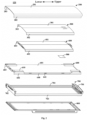
- FIG. 2 is a schematic exploded view of the door 120 of the refrigerator 100 shown in FIG. 1 .
- the door 120 of the refrigerator 100 includes: a panel 200, a display screen 300, a main control board 500, a bracket 400, an inner door lining 600, an outer door lining 800, and a trim strip group 700.
- the panel 200 has a main body 201 that constitutes a front end of the door 120, a left side 202 and a right side 203.
- the display screen 300 is disposed behind the panel 200 and has, corresponding to the structure of the panel 200, a main body 301, a left side 302 and a right side 303.
- the main control board 500 is used to control the display screen 300.
- the bracket 400 is disposed behind the display screen 300 to provide support for the display screen 300.
- the inner door lining 600 is disposed behind the bracket 400 to provide support for the bracket 400.
- the outer door lining 800 is disposed behind the inner door lining 600 to constitute a rear end of the door 120.
- the trim strip group 700 includes an upper trim strip 701 constituting an upper end of the door 120, a lower trim strip 702 constituting a lower end of the door 120, a left trim strip 703, and a right trim strip 704.
- a foaming space is confined among the inner door lining 600, the outer door lining 800, and the trim strip group 700.
- the panel 200 is preferably 3D curved glass.
- the display screen 300 is preferably an inorganic electroluminescent (EL) display screen.
- the bracket 400 and the display screen 300 are fixed by gluing.
- the door 120 of the refrigerator 100 according to the embodiment of the present invention is provided with a panel 200 having a main body 201, a left side 202 and a right side 203, and a display screen 300 having a main body 301, a left side 302 and a right side 303, and the display screen 300 is fixed by the bracket 400 and the inner door lining 600, so as to achieve a large-screen display effect with no borders or narrow borders on the left and right sides.
- FIG. 3 is a partial schematic cross-sectional view of a left part of the door 120 shown in FIG. 2 taken along the horizontal line of an auxiliary protrusion 641.
- the left side 202 of the panel 200 of the door 120 of the refrigerator 100 according to the embodiment of the present invention constitutes a left end of the door 120, and its inner side is in contact with an outer surface of the left trim strip 703;
- the right side 203 of the panel 200 constitutes a right end of the door 120, and its inner surface is in contact with an outer surface of the right trim strip 704.
- the door 120 of the refrigerator 100 according to the embodiment of the present invention can achieve a large-screen display effect without borders on the left and right sides.
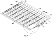
- FIG. 4 is a schematic three-dimensional diagram of the bracket 400 of the door 120 shown in FIG. 2 .
- FIG. 5 is a schematic partial enlarged view of part A of the bracket 400 shown in FIG. 4 .
- the bracket 400 of the door 120 of the refrigerator 100 according to the embodiment of the present invention has a main body 401, a left side 402 and a right side 403; the main body 401 of the bracket 400 is disposed corresponding to the main body 301 of the display screen 300; the left side 402 of the bracket 400 is disposed corresponding to the left side 302 of the display screen 300; and the right side 403 of the bracket 400 is disposed corresponding to the right side 303 of the display screen 300.
- the outer shape of the bracket 400 is the same as the inner shapes of the display screen 300 and the panel 200, and the display screen 300 can be tightly attached to the inner side of the panel 200.
- a plurality of support ribs are formed on an inner surface of the main body 401 of the bracket 400 of the door 120 of the refrigerator 100 according to the present invention.
- the support ribs can enhance the structural reliability of the bracket 400.
- the support ribs and the inner door lining 600 resist against each other, which can promote the resistance between the bracket 400 and the inner door lining 600, so that the inner door lining 600 forms a forward pressure for the bracket 400, to force the display screen 300 to be in better contact with the panel 200.
- FIG. 6 is a schematic three-dimensional diagram of the door 120 shown in FIG. 2 without the panel 200.
- FIG. 7 is a schematic partial enlarged view of part B of the door 120 shown in FIG. 6 .
- FIG. 8 is a schematic partial enlarged view of part C of the door 120 shown in FIG. 6 .
- the support ribs of the bracket 400 of the door 120 of the refrigerator 100 according to the embodiment of the present invention include horizontal support ribs 404 and vertical support ribs 405, and the horizontal support ribs 404 are provided with a plurality of ventilation openings 440.
- the upper trim strip 701 and/or the lower trim strip 702 are provided with a plurality of ventilation holes 710, and the ventilation openings 440 and the ventilation holes 710 realize heat dissipation of the display screen 300.
- Both the upper trim strip 701 and the lower trim strip 702 are provided with a plurality of ventilation holes 710. A lot of heat is released when the display screen 300 is working.
- the upper trim strip 701 and the lower trim strip 702 are provided with the ventilation holes 710, and the horizontal support ribs 404 are provided with the ventilation openings 440, so that the heat of the display screen 300 can be dissipated out of the door 120. More preferably, the left side 402 and the right side 403 of the bracket 400 are also provided with ventilation openings 440 (not shown in the figures) to enhance the heat dissipation effect.
- special-shaped protrusions 450 are formed at intervals on the plurality of vertical support ribs 405 of the bracket 400 of the door 120 of the refrigerator 100 according to the embodiment of the present invention; gaps 451 are formed between the special-shaped protrusions 450 and the vertical support ribs 405, and tops of the special-shaped protrusions resist against the inner door lining 600.
- the special-shaped protrusions 450 with gaps 451 disposed on the vertical support ribs 405 can enhance the contact between the inner door lining 600 and the bracket 400, and the gaps 451 can avoid excessive force between the inner door lining 600 and the bracket 400.
- a board installation area 460 for installing the main control board 500 is formed on the inner surface of the main body 401 of the bracket 400 of the door 120 of the refrigerator 100 according to the embodiment of the present invention.
- a board support 461 is disposed in the board installation area 460 to support and fix the main control board 500.
- a wire outlet is formed on the horizontal support ribs 404 corresponding to the board installation area 460.
- the bracket 400 of the door 120 of the refrigerator 100 according to the embodiment of the present invention further has a handle 470 to facilitate the assembly of the bracket 400 with the inner door lining 600.
- the inner door lining 600 of the door 120 of the refrigerator 100 has a main body 601, a left side 602 and a right side 603.
- Four corners of the main body 601 protrude upward respectively to form limiting portions 610, and the left side 602 and the right side 603 are recessed inward respectively to form recessed structures 640.
- the main body 401 of the bracket 400 is located in a space confined by the four limiting portions 610; the left side 402 of the bracket 400 is disposed corresponding to the recessed structure 640 of the left side 602 of the inner door lining 600; the right side 403 of the bracket 400 is disposed corresponding to the recessed structure 640 of the right side 603 of the inner door lining 600, which can achieve a guiding effect when the display screen 300 is installed in the inner door lining 600. Meanwhile, since the bracket 400 is shorter than the inner door lining 600, the upper and lower ends of the bracket 400 and the upper trim strip 701 and the lower trim strip 702 confine ventilation spaces 900 respectively, which is beneficial to the heat dissipation of the display screen 300.
- the longitudinal section of the recessed structure 640 of the inner door lining 600 of the door 120 of the refrigerator 100 according to the embodiment of the present invention is L-shaped, the recessed structure 640 has a bottom surface and a side surface, and the side surface protrudes outward to form at least one auxiliary protrusion 641.
- a bottom surface of the left side 402 of the bracket 400 resists against the bottom surface of the recessed structure 640 of the left side 602 of the inner door lining 600, and an inner surface of the left side of the bracket resists against the auxiliary protrusion 641 of the recessed structure 640 of the left side 602 of the inner door lining 600; a bottom surface of the right side 403 of the bracket 400 resists against the bottom surface of the recessed structure 640 of the right side 603 of the inner door lining 600, and an inner surface of the right side of the bracket resists against the auxiliary protrusion 641 of the recessed structure 640 of the right side 603 of the inner door lining 600.
- the auxiliary protrusions 641 can squeeze the left side 402 and the right side 403 of the bracket 400 outward, so that the left side 302 and the right side 303 of the display screen 300 are in better contact with the left side 202 and the right side 203 of the panel 200 respectively.
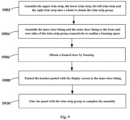
- FIG. 9 is a schematic flowchart of a method for assembling the door 120 of the refrigerator 100 shown in FIG. 1 .
- the method for assembling the door 120 of the refrigerator 100 according to the embodiment of the present invention includes the following steps:
- step S902 and S904 can adopt the existing technologies. Details are not described here.
- the method for assembling the door 120 of the refrigerator 100 obtains a large-screen display door 120 of the refrigerator 100 by assembling the trim strip group 700, the inner door lining 600 and the outer door lining 800 and foaming, then assembling the bracket 400 pasted with the display screen 300, and finally gluing the panel 200, and the method also improves the overall attractiveness of the refrigerator 100 with the glass door 120.
Landscapes
- Engineering & Computer Science (AREA)
- Chemical & Material Sciences (AREA)
- Combustion & Propulsion (AREA)
- Physics & Mathematics (AREA)
- Mechanical Engineering (AREA)
- Thermal Sciences (AREA)
- General Engineering & Computer Science (AREA)
- Refrigerator Housings (AREA)
- Cold Air Circulating Systems And Constructional Details In Refrigerators (AREA)
Description
- The present invention relates to the technical field of refrigerating and freezing devices, and in particular to a door of a refrigerator and an assembly method thereof.
- In the existing glass door of a refrigerator, a display screen can only be attached to flat or curved glass. However, because a border with a glue distance of at least 20 mm needs to be reserved, the display range of the left and right sides of the existing glass door is limited, and large-screen display cannot be achieved, which affects the display effect.
- Within the prior art, for instance
CN 106 679 293 A discloses a refrigerator door with an oversized display screen and a refrigerator with the refrigerator door. The refrigerator door comprises a first body, a control main board, a front liner plate and heating wires. The first door body comprises a front panel, a rear panel and side panels, wherein the side panels are used for being connected with the front panel and the rear panel so as to form a first containing space. The control main board is arranged in the first containing space and is close to the front panel. The front liner plate is arranged between the control main board and the rear panel. The heating wires are arranged on the wall face, close to the rear panel, of the front liner plate. The control main board comprises at least two heat production areas, namely, the first area and the second area. In the working process of the control main board, the heat release amount of the first area is larger than the heat release amount of the second area. The heating area of the heating wire corresponding to the first area is smaller than the heating area of the heating wire corresponding to the second area. According to the refrigerator door, generation of condensation on the refrigerator door is prevented by sufficiently using heat emitted by the refrigerator itself. - Wherein
WO 2018/082292 A1 teaches a door (1) used for a refrigerating and freezing apparatus, the door comprising: a panel (10) used for forming a front part of the door (1); a display control assembly (30) used for providing a display touch control function; and a door foaming assembly (20) used for forming a rear part of the door (1). The display control assembly (30) is provided between the door foam assembly (20) and the panel (10), and a forward-facing surface of the door foam assembly (20) forms a rearward recess running through from top to bottom so as to define a heat-dissipation vent, running through from top to bottom, between the door foaming assembly (20) and the display control assembly (30) and between the door foaming assembly (20) and the panel (10). - An objective of the present invention is to provide a door of a refrigerator that realizes large-screen display. The claimed subject-matter is defined by the independent claims 1 and 7. Preferred embodiments are defined by the dependent claims 2 through 6.
- A further objective of the present invention is to stably assemble a display screen.
- Particularly, the present invention provides a door of a refrigerator, including:
- a panel having a main body that constitutes a front end of the door, a left side and a right side;
- a display screen disposed behind the panel and having, corresponding to the structure of the panel, a main body, a left side and a right side;
- a main control board for controlling the display screen;
- a bracket disposed behind the display screen to provide support for the display screen;
- an inner door lining disposed behind the bracket to provide support for the bracket;
- an outer door lining disposed behind the inner door lining to constitute a rear end of the door; and
- a trim strip group, with a foaming space being confined among the inner door lining, the outer door lining and the trim strip group.
- Optionally, the trim strip group includes a left trim strip and a right trim strip;
- the left side of the panel constitutes a left end of the door, and its inner side is in contact with an outer surface of the left trim strip; and
- the right side of the panel constitutes a right end of the door, and its inner side is in contact with an outer surface of the right trim strip.
- The bracket has a main body, a left side and a right side;
- the main body of the bracket is disposed corresponding to the main body of the display screen;
- the left side of the bracket is disposed corresponding to the left side of the display screen; and
- the right side of the bracket is disposed corresponding to the right side of the display screen.
- Optionally, a board installation area is formed on an inner side of the main body of the bracket for installing the main control board.
- A plurality of support ribs are formed on the inner side of the main body of the bracket.
- The support ribs include horizontal support ribs and vertical support ribs, and the horizontal support ribs are provided with a plurality of ventilation openings; and
the trim strip group includes an upper trim strip constituting an upper end of the door and a lower trim strip constituting a lower end of the door, the upper trim strip and/or the lower trim strip are(is) provided with a plurality of ventilation holes, and the plurality of ventilation openings and the plurality of ventilation holes realize heat dissipation of the display screen. - Optionally, special-shaped protrusions are formed at intervals on the plurality of vertical support ribs; and
gaps are formed between the special-shaped protrusions and the vertical support ribs, and tops of the special-shaped protrusions resist against the inner door lining. - Optionally, the inner door lining has a main body, a left side and a right side, the main body protrudes upward to form a plurality of limiting portions, and the left side and the right side are recessed inward respectively to form recessed structures; wherein
- the main body of the bracket is located in a space confined by the plurality of limiting portions;
- the left side of the bracket is disposed corresponding to the recessed structure of the left side of the inner door lining; and
- the right side of the bracket is disposed corresponding to the recessed structure of the right side of the inner door lining.
- Optionally, the longitudinal section of the recessed structure of the inner door lining is L-shaped, the recessed structure has a bottom surface and a side surface, and the side surface protrudes outward to form at least one auxiliary protrusion; wherein
- a bottom surface of the left side of the bracket resists against the bottom surface of the recessed structure of the left side of the inner door lining, and an inner surface of the left side of the bracket resists against the auxiliary protrusion of the recessed structure of the left side of the inner door lining; and
- a bottom surface of the right side of the bracket resists against the bottom surface of the recessed structure of the right side of the inner door lining, and an inner surface of the right side of the bracket resists against the auxiliary protrusion of the recessed structure of the right side of the inner door lining.
- The present invention further discloses a method for assembling the aforementioned door of a refrigerator, including the steps of:
- assembling the trim strip group, the inner door lining and the outer door lining, and foaming;
- assembling the bracket pasted with the display screen to the inner door lining; and
- gluing the panel with the trim strip group to complete the assembly of the door.
- The door of a refrigerator according to the present invention is provided with a panel and a display screen having a main body, a left side and a right side respectively, and the display screen is fixed by the bracket and the inner door lining, so as to achieve a large-screen display effect with no borders or narrow borders on the left and right sides.
- Further, the assembly method of the present invention realizes the assembly of the large-screen display door of a refrigerator by assembling the trim strip group, the inner door lining and the outer door lining and foaming, then assembling the bracket pasted with the display screen, and finally gluing the panel.
- Specific embodiments of the present invention will be described in detail below with reference to the accompanying drawings, and those skilled in the art will better understand the above and other objectives, advantages and features of the present invention.
- Hereinafter, some specific embodiments of the present invention will be described in detail in an exemplary rather than restrictive manner with reference to the accompanying drawings. In the drawings, like reference numerals denote like or similar parts or elements. A person skilled in the art should understand that these drawings are not necessarily drawn to scale. In the figures:
-
FIG. 1 is a schematic three-dimensional diagram of a refrigerator according to an embodiment of the present invention. -
FIG. 2 is a schematic exploded view of a door of the refrigerator shown inFIG. 1 . -
FIG. 3 is a partial schematic cross-sectional view of the door shown inFIG. 2 . -
FIG. 4 is a schematic three-dimensional diagram of a bracket of the door shown inFIG. 2 . -
FIG. 5 is a schematic partial enlarged view of part A of the bracket shown inFIG. 4 . -
FIG. 6 is a schematic three-dimensional diagram of the door shown inFIG. 2 without a panel. -
FIG. 7 is a schematic partial enlarged view of part B of the door shown inFIG. 6 . -
FIG. 8 is a schematic partial enlarged view of part C of the door shown inFIG. 6 . -
FIG. 9 is a schematic flowchart of a method for assembling the door of the refrigerator shown inFIG. 1 . - In the following description, the directions or positional relationships indicated by "upper", "lower", "left", "right", etc. are based on the directions referenced by a
refrigerator 100 itself. The "upper", "lower", "left", and "right" are the directions indicated inFIG. 1 . -
FIG. 1 is a schematic three-dimensional diagram of arefrigerator 100 according to an embodiment of the present invention. Storage compartments are confined inside acabinet 110 of therefrigerator 100. The number and structure of the storage compartments can be configured according to requirements. For example,FIG. 1 shows a situation where a first storage compartment, a second storage compartment and a third storage compartment are disposed sequentially up and down. The first storage compartment is with arotary opening door 120 which is disposed on the front surface of thecabinet 110 for closing the storage compartment. The second storage compartment and the third storage compartment are provided with a firstdrawing storage device 130 and a seconddrawing storage device 140, which are disposed in the storage compartments in a drawable manner. The storage compartments can be configured as a refrigerating compartment, a freezing compartment, a variable temperature compartment or a fresh-keeping compartment according to different uses. Each storage compartment can be divided into a plurality of storage areas by partitions, and shelves or drawers are used to store items. Therefrigerator 100 according to the embodiment of the present invention may be a typical French refrigerator, and the three compartments disposed sequentially up and down are a refrigerating compartment, a freezing compartment, and a freezing compartment, respectively. -
FIG. 2 is a schematic exploded view of thedoor 120 of therefrigerator 100 shown inFIG. 1 . Thedoor 120 of therefrigerator 100 according to the embodiment of the present invention includes: apanel 200, adisplay screen 300, amain control board 500, abracket 400, an inner door lining 600, an outer door lining 800, and atrim strip group 700. Thepanel 200 has amain body 201 that constitutes a front end of thedoor 120, aleft side 202 and aright side 203. Thedisplay screen 300 is disposed behind thepanel 200 and has, corresponding to the structure of thepanel 200, amain body 301, aleft side 302 and aright side 303. Themain control board 500 is used to control thedisplay screen 300. Thebracket 400 is disposed behind thedisplay screen 300 to provide support for thedisplay screen 300. The inner door lining 600 is disposed behind thebracket 400 to provide support for thebracket 400. The outer door lining 800 is disposed behind the inner door lining 600 to constitute a rear end of thedoor 120. Thetrim strip group 700 includes anupper trim strip 701 constituting an upper end of thedoor 120, alower trim strip 702 constituting a lower end of thedoor 120, aleft trim strip 703, and aright trim strip 704. A foaming space is confined among the inner door lining 600, the outer door lining 800, and thetrim strip group 700. Thepanel 200 is preferably 3D curved glass. Thedisplay screen 300 is preferably an inorganic electroluminescent (EL) display screen. Thebracket 400 and thedisplay screen 300 are fixed by gluing. Thedoor 120 of therefrigerator 100 according to the embodiment of the present invention is provided with apanel 200 having amain body 201, aleft side 202 and aright side 203, and adisplay screen 300 having amain body 301, aleft side 302 and aright side 303, and thedisplay screen 300 is fixed by thebracket 400 and the inner door lining 600, so as to achieve a large-screen display effect with no borders or narrow borders on the left and right sides. -
FIG. 3 is a partial schematic cross-sectional view of a left part of thedoor 120 shown inFIG. 2 taken along the horizontal line of anauxiliary protrusion 641. In some embodiments, theleft side 202 of thepanel 200 of thedoor 120 of therefrigerator 100 according to the embodiment of the present invention constitutes a left end of thedoor 120, and its inner side is in contact with an outer surface of theleft trim strip 703; theright side 203 of thepanel 200 constitutes a right end of thedoor 120, and its inner surface is in contact with an outer surface of theright trim strip 704. With this structure, thedoor 120 of therefrigerator 100 according to the embodiment of the present invention can achieve a large-screen display effect without borders on the left and right sides. -
FIG. 4 is a schematic three-dimensional diagram of thebracket 400 of thedoor 120 shown inFIG. 2 .FIG. 5 is a schematic partial enlarged view of part A of thebracket 400 shown inFIG. 4 . Thebracket 400 of thedoor 120 of therefrigerator 100 according to the embodiment of the present invention has amain body 401, aleft side 402 and aright side 403; themain body 401 of thebracket 400 is disposed corresponding to themain body 301 of thedisplay screen 300; theleft side 402 of thebracket 400 is disposed corresponding to theleft side 302 of thedisplay screen 300; and theright side 403 of thebracket 400 is disposed corresponding to theright side 303 of thedisplay screen 300. The outer shape of thebracket 400 is the same as the inner shapes of thedisplay screen 300 and thepanel 200, and thedisplay screen 300 can be tightly attached to the inner side of thepanel 200. - A plurality of support ribs are formed on an inner surface of the
main body 401 of thebracket 400 of thedoor 120 of therefrigerator 100 according to the present invention. The support ribs can enhance the structural reliability of thebracket 400. Meanwhile, the support ribs and the inner door lining 600 resist against each other, which can promote the resistance between thebracket 400 and the inner door lining 600, so that the inner door lining 600 forms a forward pressure for thebracket 400, to force thedisplay screen 300 to be in better contact with thepanel 200. -
FIG. 6 is a schematic three-dimensional diagram of thedoor 120 shown inFIG. 2 without thepanel 200.FIG. 7 is a schematic partial enlarged view of part B of thedoor 120 shown inFIG. 6 .FIG. 8 is a schematic partial enlarged view of part C of thedoor 120 shown inFIG. 6 . The support ribs of thebracket 400 of thedoor 120 of therefrigerator 100 according to the embodiment of the present invention includehorizontal support ribs 404 andvertical support ribs 405, and thehorizontal support ribs 404 are provided with a plurality ofventilation openings 440. Theupper trim strip 701 and/or thelower trim strip 702 are provided with a plurality ofventilation holes 710, and theventilation openings 440 and the ventilation holes 710 realize heat dissipation of thedisplay screen 300. Both theupper trim strip 701 and thelower trim strip 702 are provided with a plurality of ventilation holes 710. A lot of heat is released when thedisplay screen 300 is working. Theupper trim strip 701 and thelower trim strip 702 are provided with the ventilation holes 710, and thehorizontal support ribs 404 are provided with theventilation openings 440, so that the heat of thedisplay screen 300 can be dissipated out of thedoor 120. More preferably, theleft side 402 and theright side 403 of thebracket 400 are also provided with ventilation openings 440 (not shown in the figures) to enhance the heat dissipation effect. - In some embodiments, special-shaped
protrusions 450 are formed at intervals on the plurality ofvertical support ribs 405 of thebracket 400 of thedoor 120 of therefrigerator 100 according to the embodiment of the present invention;gaps 451 are formed between the special-shapedprotrusions 450 and thevertical support ribs 405, and tops of the special-shaped protrusions resist against the inner door lining 600. The special-shapedprotrusions 450 withgaps 451 disposed on thevertical support ribs 405 can enhance the contact between the inner door lining 600 and thebracket 400, and thegaps 451 can avoid excessive force between the inner door lining 600 and thebracket 400. - In some embodiments, a
board installation area 460 for installing themain control board 500 is formed on the inner surface of themain body 401 of thebracket 400 of thedoor 120 of therefrigerator 100 according to the embodiment of the present invention. Aboard support 461 is disposed in theboard installation area 460 to support and fix themain control board 500. A wire outlet is formed on thehorizontal support ribs 404 corresponding to theboard installation area 460. - In some embodiments, the
bracket 400 of thedoor 120 of therefrigerator 100 according to the embodiment of the present invention further has ahandle 470 to facilitate the assembly of thebracket 400 with the inner door lining 600. - In some embodiments, the inner door lining 600 of the
door 120 of therefrigerator 100 according to the embodiment of the present invention has amain body 601, aleft side 602 and aright side 603. Four corners of themain body 601 protrude upward respectively to form limitingportions 610, and theleft side 602 and theright side 603 are recessed inward respectively to form recessedstructures 640. Themain body 401 of thebracket 400 is located in a space confined by the four limitingportions 610; theleft side 402 of thebracket 400 is disposed corresponding to the recessedstructure 640 of theleft side 602 of the inner door lining 600; theright side 403 of thebracket 400 is disposed corresponding to the recessedstructure 640 of theright side 603 of the inner door lining 600, which can achieve a guiding effect when thedisplay screen 300 is installed in the inner door lining 600. Meanwhile, since thebracket 400 is shorter than the inner door lining 600, the upper and lower ends of thebracket 400 and theupper trim strip 701 and thelower trim strip 702 confineventilation spaces 900 respectively, which is beneficial to the heat dissipation of thedisplay screen 300. - In some embodiments, the longitudinal section of the recessed
structure 640 of the inner door lining 600 of thedoor 120 of therefrigerator 100 according to the embodiment of the present invention is L-shaped, the recessedstructure 640 has a bottom surface and a side surface, and the side surface protrudes outward to form at least oneauxiliary protrusion 641. A bottom surface of theleft side 402 of thebracket 400 resists against the bottom surface of the recessedstructure 640 of theleft side 602 of the inner door lining 600, and an inner surface of the left side of the bracket resists against theauxiliary protrusion 641 of the recessedstructure 640 of theleft side 602 of the inner door lining 600; a bottom surface of theright side 403 of thebracket 400 resists against the bottom surface of the recessedstructure 640 of theright side 603 of the inner door lining 600, and an inner surface of the right side of the bracket resists against theauxiliary protrusion 641 of the recessedstructure 640 of theright side 603 of the inner door lining 600. Theauxiliary protrusions 641 can squeeze theleft side 402 and theright side 403 of thebracket 400 outward, so that theleft side 302 and theright side 303 of thedisplay screen 300 are in better contact with theleft side 202 and theright side 203 of thepanel 200 respectively. -
FIG. 9 is a schematic flowchart of a method for assembling thedoor 120 of therefrigerator 100 shown inFIG. 1 . The method for assembling thedoor 120 of therefrigerator 100 according to the embodiment of the present invention includes the following steps: - S902: the
upper trim strip 701, thelower trim strip 702, theleft trim strip 703 and theright trim strip 704 are assembled into a whole to obtain thetrim strip group 700; - S904: the inner door lining 600 and the outer door lining 800 are assembled to the front and rear sides of the
trim strip group 700 respectively to confine a foaming space; - S906: a foamed
door 120 is obtained by foaming; - S908: the
bracket 400 pasted with thedisplay screen 300 is embedded in the inner door lining 600; - S910: the
panel 200 is glued with theupper trim strip 701, thelower trim strip 702, theleft trim strip 703 and theright trim strip 704 respectively, to complete the assembly. - The specific assembly process of steps S902 and S904, and the specific foaming process of step S906 can adopt the existing technologies. Details are not described here.
- The method for assembling the
door 120 of therefrigerator 100 according to the embodiment of the present invention obtains a large-screen display door 120 of therefrigerator 100 by assembling thetrim strip group 700, the inner door lining 600 and the outer door lining 800 and foaming, then assembling thebracket 400 pasted with thedisplay screen 300, and finally gluing thepanel 200, and the method also improves the overall attractiveness of therefrigerator 100 with theglass door 120. - So far, those skilled in the art should realize that although multiple exemplary embodiments of the present invention are illustrated and described in detail herein, many other variations or modifications that conform to the principle of the present invention may still be directly determined or derived from the disclosure of the present invention without departing from the scope of the present invention. Therefore, the scope of the present invention should be understood and deemed to cover all these other variations or modifications.
Claims (7)
- A door (120) of a refrigerator (100), comprising:a panel (200) having a main body (201) that constitutes a front end of the door, a left side (202) and a right side (203);a display screen (300) disposed behind the panel (200) and having, corresponding to the structure of the panel (200), a main body (301), a left side (302) and a right side (303);a main control board (500) for controlling the display screen (300);a bracket (400) disposed behind the display screen (300) to provide support for the display screen (300);an inner door lining (600) disposed behind the bracket (400) to provide support for the bracket (400);an outer door lining (800) disposed behind the inner door lining (600) to constitute a rear end of the door (120); anda trim strip group (700), with a foaming space being confined among the inner door lining (600), the outer door lining (800) and the trim strip group (700), whereinthe bracket (400) has a main body (401), a left side (402) and a right side (403);the main body (401) of the bracket (400) is disposed corresponding to the main body (301) of the display screen (300);the left side (402) of the bracket (400) is disposed corresponding to the left side (302) of the display screen (300); andthe right side (403) of the bracket (400) is disposed corresponding to the right side (303) of the display screen (300), characterized in thata plurality of support ribs are formed on the inner side of the main body (401) of the bracket (400), whereinthe support ribs comprise horizontal support ribs (404) and vertical support ribs (405), and the horizontal support ribs (404) are provided with a plurality of ventilation openings (440); andthe trim strip group (700) comprises an upper trim strip (701) constituting an upper end of the door and a lower trim strip (702) constituting a lower end of the door, the upper trim strip (701) and the lower trim strip (702) are provided with a plurality of ventilation holes (710), and the plurality of ventilation openings (440) and the plurality of ventilation holes (710) realize heat dissipation of the display screen (300).
- The door (120) of a refrigerator (100) according to claim 1, whereinthe trim strip group (700) comprises a left trim strip (703) and a right trim strip (704);the left side (202) of the panel (200) constitutes a left end of the door (120), and its inner side is in contact with an outer surface of the left trim strip (703); andthe right side (203) of the panel (200) constitutes a right end of the door (120), and its inner side is in contact with an outer surface of the right trim strip (704).
- The door (120) of a refrigerator (100) according to claim 1, wherein
a board installation area (460) is formed on an inner side of the main body (401) of the bracket (400) for installing the main control board (500). - The door (120) of a refrigerator (100) according to claim 1, whereinspecial-shaped protrusions (450) are formed at intervals on the plurality of vertical support ribs (405); andgaps (451) are formed between the special-shaped protrusions (450) and the vertical support ribs (405), and tops of the special-shaped protrusions (450) resist against the inner door lining (600).
- The door (120) of a refrigerator (100) according to any one of claims 3 or 4, whereinthe inner door lining (600) has a main body (601), a left side (602) and a right side (603), the main body (601) protrudes upward to form a plurality of limiting portions (610), and the left side (602) and the right side (603) are recessed inward respectively to form recessed structures (640); whereinthe main body (401) of the bracket (400) is located in a space confined by the plurality of limiting portions (610);the left side (402) of the bracket (400) is disposed corresponding to the recessed structure (640) of the left side (602) of the inner door lining (600); andthe right side (403) of the bracket (400) is disposed corresponding to the recessed structure (640) of the right side (603) of the inner door lining (600).
- The door (120) of a refrigerator (100) according to claim 5, whereinthe longitudinal section of the recessed structure (640) of the inner door lining (600) is L-shaped, the recessed structure (640) has a bottom surface and a side surface, and the side surface protrudes outward to form at least one auxiliary protrusion (641); whereina bottom surface of the left side (402) of the bracket (400) resists against the bottom surface of the recessed structure (640) of the left side (602) of the inner door lining (600), and an inner surface of the left side (402) of the bracket (400) resists against the auxiliary protrusion (641) of the recessed structure of the left side (602) of the inner door lining (600); anda bottom surface of the right side (403) of the bracket (400) resists against the bottom surface of the recessed structure of the right side (603) of the inner door lining (600), and an inner surface of the right side (403) of the bracket (400) resists against the auxiliary protrusion (641) of the recessed structure of the right side (603) of the inner door lining (600).
- A method for assembling the door (120) of a refrigerator (100) according to any one of claims 1-6, comprising the steps of:assembling the trim strip group (700), the inner door lining (600) and the outer door lining (800), and foaming;assembling the bracket (400) pasted with the display screen (300) to the inner door lining (600); andgluing the panel (200) with the trim strip group (700) to complete the assembly of the door (120).
Applications Claiming Priority (2)
| Application Number | Priority Date | Filing Date | Title |
|---|---|---|---|
| CN201910713632.5A CN112304009B (en) | 2019-08-02 | 2019-08-02 | Refrigerator door and assembling method thereof |
| PCT/CN2020/105502 WO2021023077A1 (en) | 2019-08-02 | 2020-07-29 | Door body for refrigerator and assembly method therefor |
Publications (3)
| Publication Number | Publication Date |
|---|---|
| EP3992554A1 EP3992554A1 (en) | 2022-05-04 |
| EP3992554A4 EP3992554A4 (en) | 2022-08-31 |
| EP3992554B1 true EP3992554B1 (en) | 2024-09-18 |
Family
ID=74486684
Family Applications (1)
| Application Number | Title | Priority Date | Filing Date |
|---|---|---|---|
| EP20849480.7A Active EP3992554B1 (en) | 2019-08-02 | 2020-07-29 | Door body for refrigerator and assembly method therefor |
Country Status (4)
| Country | Link |
|---|---|
| US (1) | US12038225B2 (en) |
| EP (1) | EP3992554B1 (en) |
| CN (1) | CN112304009B (en) |
| WO (1) | WO2021023077A1 (en) |
Families Citing this family (3)
| Publication number | Priority date | Publication date | Assignee | Title |
|---|---|---|---|---|
| CN113865234B (en) * | 2020-06-30 | 2022-11-29 | 青岛海尔电冰箱有限公司 | Refrigerator door with replaceable door face |
| CN114061257A (en) * | 2021-11-17 | 2022-02-18 | 长虹美菱股份有限公司 | Display screen assembly, refrigerator door body and installation method |
| CN116558211A (en) * | 2023-06-21 | 2023-08-08 | 长虹美菱股份有限公司 | refrigerator door lining |
Family Cites Families (35)
| Publication number | Priority date | Publication date | Assignee | Title |
|---|---|---|---|---|
| US5007226A (en) * | 1989-05-01 | 1991-04-16 | Soltech, Inc. | Insulated refrigerator door construction |
| DE10302797B4 (en) * | 2003-01-24 | 2025-05-28 | BSH Hausgeräte GmbH | Door for a refrigeration appliance and refrigeration appliance comprising a door |
| CN101131288B (en) * | 2006-08-22 | 2012-06-13 | 泰州乐金电子冷机有限公司 | Front panel mounting structure of refrigerator door |
| CN101469933B (en) * | 2007-12-28 | 2012-03-14 | 博西华电器(江苏)有限公司 | Household electrical appliance with multimedia apparatus |
| KR101576672B1 (en) * | 2008-02-21 | 2015-12-10 | 엘지전자 주식회사 | Refrigerator and refrigerator door |
| CN102116554A (en) * | 2010-01-04 | 2011-07-06 | Lg电子株式会社 | Refrigerator |
| KR102238962B1 (en) * | 2014-01-07 | 2021-04-12 | 삼성전자주식회사 | Refrigerator and door assembly applying the same and manufacturing method the same |
| CN105258437B (en) * | 2014-07-18 | 2019-02-26 | 博西华电器(江苏)有限公司 | Doors for refrigerators and refrigerators |
| CN105333680B (en) * | 2014-07-18 | 2019-02-26 | 博西华电器(江苏)有限公司 | refrigerator |
| KR102023152B1 (en) * | 2014-11-07 | 2019-09-20 | 엘지전자 주식회사 | Refrigerator |
| CN204480603U (en) * | 2014-12-19 | 2015-07-15 | 上海协度电子科技有限公司 | Rimless display screen |
| KR102470037B1 (en) * | 2015-09-01 | 2022-11-23 | 삼성전자주식회사 | Refrigerator |
| KR101810760B1 (en) * | 2016-01-05 | 2017-12-19 | 엘지전자 주식회사 | Refirgerator and control merthod thereof |
| KR101856835B1 (en) * | 2016-01-05 | 2018-05-10 | 엘지전자 주식회사 | Refirgerator |
| KR101829352B1 (en) * | 2016-01-05 | 2018-03-29 | 엘지전자 주식회사 | Refirgerator |
| CN105571237B (en) | 2016-01-27 | 2018-12-14 | 青岛海尔股份有限公司 | The preparation method of door body for refrigerator, door body and refrigerator for refrigerator |
| CN106091552B (en) | 2016-07-22 | 2018-10-12 | 青岛海尔股份有限公司 | Refrigerating device, door body and its installation method for refrigerating device |
| KR101802667B1 (en) * | 2016-08-25 | 2017-11-28 | 엘지전자 주식회사 | Touch sensor assembly for home appliance and manufacturing method thereof |
| CN206257870U (en) * | 2016-09-30 | 2017-06-16 | 合肥华凌股份有限公司 | A kind of novel intelligent large-size screen monitors mounting assembly, refrigerator door and refrigerator |
| CN106642943B (en) | 2016-11-02 | 2019-08-02 | 青岛海尔股份有限公司 | Door body for refrigerating and freezing devices and refrigerating and freezing devices |
| CN106610166B (en) * | 2016-11-02 | 2019-05-03 | 青岛海尔股份有限公司 | Doors and refrigerated-freezers for refrigerated-freezers |
| KR102704899B1 (en) * | 2016-12-12 | 2024-09-09 | 엘지전자 주식회사 | Refrigerator |
| KR102273092B1 (en) * | 2016-12-12 | 2021-07-06 | 엘지전자 주식회사 | Refrigerator |
| CN106642946B (en) | 2016-12-13 | 2020-07-28 | 青岛海尔股份有限公司 | A door body and a refrigerating and freezing device comprising the door body |
| CN106524657B (en) * | 2016-12-13 | 2024-02-27 | 海尔智家股份有限公司 | A door body and a refrigeration and freezing device including the door body |
| CN106679293B (en) * | 2017-01-09 | 2019-03-08 | 青岛海尔股份有限公司 | Refrigerator door with extra-large display screen and refrigerator with the same |
| US10295248B2 (en) * | 2017-01-09 | 2019-05-21 | Electrolux Home Products, Inc. | Refrigerator with glass door |
| KR102733673B1 (en) * | 2017-01-23 | 2024-11-26 | 엘지전자 주식회사 | Refrigerator and panel assembly for refrigerator |
| CN206787156U (en) | 2017-04-26 | 2017-12-22 | 合肥美菱股份有限公司 | A kind of transparent refrigerator door body with touch screen structure |
| CN207318893U (en) | 2017-11-10 | 2018-05-04 | 江西合力泰科技有限公司 | The curved backlight source modules of 2.5D |
| KR102499468B1 (en) * | 2018-02-12 | 2023-02-15 | 엘지전자 주식회사 | Refrigerator |
| CN108759269A (en) * | 2018-06-15 | 2018-11-06 | 青岛海尔股份有限公司 | Door body and refrigerator for refrigerator |
| CN109323530A (en) | 2018-07-18 | 2019-02-12 | 佛山市云米电器科技有限公司 | The display screen component connection structure of household appliances |
| CN112797711A (en) * | 2019-11-13 | 2021-05-14 | Lg电子株式会社 | refrigerator |
| KR102957481B1 (en) * | 2020-04-08 | 2026-04-27 | 삼성전자주식회사 | Refrigerator |
-
2019
- 2019-08-02 CN CN201910713632.5A patent/CN112304009B/en active Active
-
2020
- 2020-07-29 EP EP20849480.7A patent/EP3992554B1/en active Active
- 2020-07-29 US US17/632,306 patent/US12038225B2/en active Active
- 2020-07-29 WO PCT/CN2020/105502 patent/WO2021023077A1/en not_active Ceased
Also Published As
| Publication number | Publication date |
|---|---|
| US20220290910A1 (en) | 2022-09-15 |
| CN112304009A (en) | 2021-02-02 |
| EP3992554A1 (en) | 2022-05-04 |
| CN112304009B (en) | 2022-01-21 |
| WO2021023077A1 (en) | 2021-02-11 |
| EP3992554A4 (en) | 2022-08-31 |
| US12038225B2 (en) | 2024-07-16 |
Similar Documents
| Publication | Publication Date | Title |
|---|---|---|
| KR101346502B1 (en) | Refrigerator and method for manufacturing a door of refrigerator | |
| US12038225B2 (en) | Door of refrigerator and assembly method thereof | |
| US3933398A (en) | Refrigeration apparatus enclosure structure | |
| CN203687503U (en) | Door for refrigerator and refrigerator | |
| US4043624A (en) | Refrigeration apparatus wall structure | |
| KR102102642B1 (en) | Door for Refrigerator, Manufacturing Method for the same and Refrigerator | |
| US3910658A (en) | Refrigeration apparatus enclosure structure | |
| JP2021038921A (en) | refrigerator | |
| CN106091552B (en) | Refrigerating device, door body and its installation method for refrigerating device | |
| CN205860639U (en) | The refrigerator doors of a kind of band display screen and there is its refrigerator | |
| KR100634365B1 (en) | Refrigerator door and method for manufacturing same | |
| AU2023214380B2 (en) | Refrigerator | |
| US3999820A (en) | Refrigeration apparatus enclosure structure | |
| US7845189B2 (en) | Door for a refrigeration device | |
| CN207797504U (en) | Visual thermal insulation refrigerator drawer and the refrigerator with it | |
| CN217031787U (en) | Refrigerator with improved shelf supporting structure | |
| JP6078433B2 (en) | refrigerator | |
| US4033806A (en) | Method of making refrigeration apparatus enclosure structure | |
| JP2005331221A (en) | Refrigerator and refrigerator assembly method | |
| KR100644253B1 (en) | Mounting structure of display case of door for refrigerator | |
| CN202719830U (en) | Display structure of refrigerator | |
| KR20190106494A (en) | Refrigerator | |
| CN103615856B (en) | Refrigerator and refrigerator container | |
| CN212939077U (en) | Refrigeration and freezing display cabinet | |
| KR100745777B1 (en) | Status indicator refrigerator |
Legal Events
| Date | Code | Title | Description |
|---|---|---|---|
| STAA | Information on the status of an ep patent application or granted ep patent |
Free format text: STATUS: THE INTERNATIONAL PUBLICATION HAS BEEN MADE |
|
| PUAI | Public reference made under article 153(3) epc to a published international application that has entered the european phase |
Free format text: ORIGINAL CODE: 0009012 |
|
| STAA | Information on the status of an ep patent application or granted ep patent |
Free format text: STATUS: REQUEST FOR EXAMINATION WAS MADE |
|
| 17P | Request for examination filed |
Effective date: 20220125 |
|
| AK | Designated contracting states |
Kind code of ref document: A1 Designated state(s): AL AT BE BG CH CY CZ DE DK EE ES FI FR GB GR HR HU IE IS IT LI LT LU LV MC MK MT NL NO PL PT RO RS SE SI SK SM TR |
|
| STAA | Information on the status of an ep patent application or granted ep patent |
Free format text: STATUS: EXAMINATION IS IN PROGRESS |
|
| A4 | Supplementary search report drawn up and despatched |
Effective date: 20220803 |
|
| RIC1 | Information provided on ipc code assigned before grant |
Ipc: F25D 29/00 20060101ALI20220728BHEP Ipc: F25D 23/02 20060101AFI20220728BHEP |
|
| 17Q | First examination report despatched |
Effective date: 20220816 |
|
| DAV | Request for validation of the european patent (deleted) | ||
| DAX | Request for extension of the european patent (deleted) | ||
| GRAP | Despatch of communication of intention to grant a patent |
Free format text: ORIGINAL CODE: EPIDOSNIGR1 |
|
| STAA | Information on the status of an ep patent application or granted ep patent |
Free format text: STATUS: GRANT OF PATENT IS INTENDED |
|
| RIC1 | Information provided on ipc code assigned before grant |
Ipc: F25D 29/00 20060101ALI20240614BHEP Ipc: F25D 23/02 20060101AFI20240614BHEP |
|
| INTG | Intention to grant announced |
Effective date: 20240709 |
|
| GRAS | Grant fee paid |
Free format text: ORIGINAL CODE: EPIDOSNIGR3 |
|
| GRAA | (expected) grant |
Free format text: ORIGINAL CODE: 0009210 |
|
| STAA | Information on the status of an ep patent application or granted ep patent |
Free format text: STATUS: THE PATENT HAS BEEN GRANTED |
|
| AK | Designated contracting states |
Kind code of ref document: B1 Designated state(s): AL AT BE BG CH CY CZ DE DK EE ES FI FR GB GR HR HU IE IS IT LI LT LU LV MC MK MT NL NO PL PT RO RS SE SI SK SM TR |
|
| REG | Reference to a national code |
Ref country code: GB Ref legal event code: FG4D |
|
| REG | Reference to a national code |
Ref country code: CH Ref legal event code: EP |
|
| REG | Reference to a national code |
Ref country code: DE Ref legal event code: R096 Ref document number: 602020038098 Country of ref document: DE |
|
| REG | Reference to a national code |
Ref country code: IE Ref legal event code: FG4D |
|
| REG | Reference to a national code |
Ref country code: LT Ref legal event code: MG9D |
|
| PG25 | Lapsed in a contracting state [announced via postgrant information from national office to epo] |
Ref country code: NO Free format text: LAPSE BECAUSE OF FAILURE TO SUBMIT A TRANSLATION OF THE DESCRIPTION OR TO PAY THE FEE WITHIN THE PRESCRIBED TIME-LIMIT Effective date: 20241218 |
|
| PG25 | Lapsed in a contracting state [announced via postgrant information from national office to epo] |
Ref country code: GR Free format text: LAPSE BECAUSE OF FAILURE TO SUBMIT A TRANSLATION OF THE DESCRIPTION OR TO PAY THE FEE WITHIN THE PRESCRIBED TIME-LIMIT Effective date: 20241219 Ref country code: FI Free format text: LAPSE BECAUSE OF FAILURE TO SUBMIT A TRANSLATION OF THE DESCRIPTION OR TO PAY THE FEE WITHIN THE PRESCRIBED TIME-LIMIT Effective date: 20240918 |
|
| PG25 | Lapsed in a contracting state [announced via postgrant information from national office to epo] |
Ref country code: BG Free format text: LAPSE BECAUSE OF FAILURE TO SUBMIT A TRANSLATION OF THE DESCRIPTION OR TO PAY THE FEE WITHIN THE PRESCRIBED TIME-LIMIT Effective date: 20240918 |
|
| PG25 | Lapsed in a contracting state [announced via postgrant information from national office to epo] |
Ref country code: LV Free format text: LAPSE BECAUSE OF FAILURE TO SUBMIT A TRANSLATION OF THE DESCRIPTION OR TO PAY THE FEE WITHIN THE PRESCRIBED TIME-LIMIT Effective date: 20240918 |
|
| PG25 | Lapsed in a contracting state [announced via postgrant information from national office to epo] |
Ref country code: HR Free format text: LAPSE BECAUSE OF FAILURE TO SUBMIT A TRANSLATION OF THE DESCRIPTION OR TO PAY THE FEE WITHIN THE PRESCRIBED TIME-LIMIT Effective date: 20240918 |
|
| REG | Reference to a national code |
Ref country code: NL Ref legal event code: MP Effective date: 20240918 |
|
| PG25 | Lapsed in a contracting state [announced via postgrant information from national office to epo] |
Ref country code: RS Free format text: LAPSE BECAUSE OF FAILURE TO SUBMIT A TRANSLATION OF THE DESCRIPTION OR TO PAY THE FEE WITHIN THE PRESCRIBED TIME-LIMIT Effective date: 20241218 |
|
| PG25 | Lapsed in a contracting state [announced via postgrant information from national office to epo] |
Ref country code: RS Free format text: LAPSE BECAUSE OF FAILURE TO SUBMIT A TRANSLATION OF THE DESCRIPTION OR TO PAY THE FEE WITHIN THE PRESCRIBED TIME-LIMIT Effective date: 20241218 Ref country code: NO Free format text: LAPSE BECAUSE OF FAILURE TO SUBMIT A TRANSLATION OF THE DESCRIPTION OR TO PAY THE FEE WITHIN THE PRESCRIBED TIME-LIMIT Effective date: 20241218 Ref country code: LV Free format text: LAPSE BECAUSE OF FAILURE TO SUBMIT A TRANSLATION OF THE DESCRIPTION OR TO PAY THE FEE WITHIN THE PRESCRIBED TIME-LIMIT Effective date: 20240918 Ref country code: HR Free format text: LAPSE BECAUSE OF FAILURE TO SUBMIT A TRANSLATION OF THE DESCRIPTION OR TO PAY THE FEE WITHIN THE PRESCRIBED TIME-LIMIT Effective date: 20240918 Ref country code: GR Free format text: LAPSE BECAUSE OF FAILURE TO SUBMIT A TRANSLATION OF THE DESCRIPTION OR TO PAY THE FEE WITHIN THE PRESCRIBED TIME-LIMIT Effective date: 20241219 Ref country code: FI Free format text: LAPSE BECAUSE OF FAILURE TO SUBMIT A TRANSLATION OF THE DESCRIPTION OR TO PAY THE FEE WITHIN THE PRESCRIBED TIME-LIMIT Effective date: 20240918 Ref country code: BG Free format text: LAPSE BECAUSE OF FAILURE TO SUBMIT A TRANSLATION OF THE DESCRIPTION OR TO PAY THE FEE WITHIN THE PRESCRIBED TIME-LIMIT Effective date: 20240918 |
|
| REG | Reference to a national code |
Ref country code: AT Ref legal event code: MK05 Ref document number: 1725008 Country of ref document: AT Kind code of ref document: T Effective date: 20240918 |
|
| PG25 | Lapsed in a contracting state [announced via postgrant information from national office to epo] |
Ref country code: NL Free format text: LAPSE BECAUSE OF FAILURE TO SUBMIT A TRANSLATION OF THE DESCRIPTION OR TO PAY THE FEE WITHIN THE PRESCRIBED TIME-LIMIT Effective date: 20240918 |
|
| PG25 | Lapsed in a contracting state [announced via postgrant information from national office to epo] |
Ref country code: IS Free format text: LAPSE BECAUSE OF FAILURE TO SUBMIT A TRANSLATION OF THE DESCRIPTION OR TO PAY THE FEE WITHIN THE PRESCRIBED TIME-LIMIT Effective date: 20250118 Ref country code: PT Free format text: LAPSE BECAUSE OF FAILURE TO SUBMIT A TRANSLATION OF THE DESCRIPTION OR TO PAY THE FEE WITHIN THE PRESCRIBED TIME-LIMIT Effective date: 20250120 |
|
| PG25 | Lapsed in a contracting state [announced via postgrant information from national office to epo] |
Ref country code: RO Free format text: LAPSE BECAUSE OF FAILURE TO SUBMIT A TRANSLATION OF THE DESCRIPTION OR TO PAY THE FEE WITHIN THE PRESCRIBED TIME-LIMIT Effective date: 20240918 Ref country code: SM Free format text: LAPSE BECAUSE OF FAILURE TO SUBMIT A TRANSLATION OF THE DESCRIPTION OR TO PAY THE FEE WITHIN THE PRESCRIBED TIME-LIMIT Effective date: 20240918 |
|
| PG25 | Lapsed in a contracting state [announced via postgrant information from national office to epo] |
Ref country code: ES Free format text: LAPSE BECAUSE OF FAILURE TO SUBMIT A TRANSLATION OF THE DESCRIPTION OR TO PAY THE FEE WITHIN THE PRESCRIBED TIME-LIMIT Effective date: 20240918 |
|
| PG25 | Lapsed in a contracting state [announced via postgrant information from national office to epo] |
Ref country code: AT Free format text: LAPSE BECAUSE OF FAILURE TO SUBMIT A TRANSLATION OF THE DESCRIPTION OR TO PAY THE FEE WITHIN THE PRESCRIBED TIME-LIMIT Effective date: 20240918 Ref country code: EE Free format text: LAPSE BECAUSE OF FAILURE TO SUBMIT A TRANSLATION OF THE DESCRIPTION OR TO PAY THE FEE WITHIN THE PRESCRIBED TIME-LIMIT Effective date: 20240918 |
|
| PG25 | Lapsed in a contracting state [announced via postgrant information from national office to epo] |
Ref country code: CZ Free format text: LAPSE BECAUSE OF FAILURE TO SUBMIT A TRANSLATION OF THE DESCRIPTION OR TO PAY THE FEE WITHIN THE PRESCRIBED TIME-LIMIT Effective date: 20240918 Ref country code: PL Free format text: LAPSE BECAUSE OF FAILURE TO SUBMIT A TRANSLATION OF THE DESCRIPTION OR TO PAY THE FEE WITHIN THE PRESCRIBED TIME-LIMIT Effective date: 20240918 |
|
| PG25 | Lapsed in a contracting state [announced via postgrant information from national office to epo] |
Ref country code: SK Free format text: LAPSE BECAUSE OF FAILURE TO SUBMIT A TRANSLATION OF THE DESCRIPTION OR TO PAY THE FEE WITHIN THE PRESCRIBED TIME-LIMIT Effective date: 20240918 Ref country code: IT Free format text: LAPSE BECAUSE OF FAILURE TO SUBMIT A TRANSLATION OF THE DESCRIPTION OR TO PAY THE FEE WITHIN THE PRESCRIBED TIME-LIMIT Effective date: 20240918 |
|
| REG | Reference to a national code |
Ref country code: DE Ref legal event code: R097 Ref document number: 602020038098 Country of ref document: DE |
|
| PG25 | Lapsed in a contracting state [announced via postgrant information from national office to epo] |
Ref country code: DK Free format text: LAPSE BECAUSE OF FAILURE TO SUBMIT A TRANSLATION OF THE DESCRIPTION OR TO PAY THE FEE WITHIN THE PRESCRIBED TIME-LIMIT Effective date: 20240918 |
|
| PLBE | No opposition filed within time limit |
Free format text: ORIGINAL CODE: 0009261 |
|
| STAA | Information on the status of an ep patent application or granted ep patent |
Free format text: STATUS: NO OPPOSITION FILED WITHIN TIME LIMIT |
|
| 26N | No opposition filed |
Effective date: 20250619 |
|
| PG25 | Lapsed in a contracting state [announced via postgrant information from national office to epo] |
Ref country code: SE Free format text: LAPSE BECAUSE OF FAILURE TO SUBMIT A TRANSLATION OF THE DESCRIPTION OR TO PAY THE FEE WITHIN THE PRESCRIBED TIME-LIMIT Effective date: 20240918 |
|
| PGFP | Annual fee paid to national office [announced via postgrant information from national office to epo] |
Ref country code: DE Payment date: 20250711 Year of fee payment: 6 |
|
| PGFP | Annual fee paid to national office [announced via postgrant information from national office to epo] |
Ref country code: GB Payment date: 20250723 Year of fee payment: 6 |
|
| PGFP | Annual fee paid to national office [announced via postgrant information from national office to epo] |
Ref country code: FR Payment date: 20250730 Year of fee payment: 6 |
|
| REG | Reference to a national code |
Ref country code: CH Ref legal event code: H13 Free format text: ST27 STATUS EVENT CODE: U-0-0-H10-H13 (AS PROVIDED BY THE NATIONAL OFFICE) Effective date: 20260224 |
|
| PG25 | Lapsed in a contracting state [announced via postgrant information from national office to epo] |
Ref country code: LU Free format text: LAPSE BECAUSE OF NON-PAYMENT OF DUE FEES Effective date: 20250729 |
|
| REG | Reference to a national code |
Ref country code: BE Ref legal event code: MM Effective date: 20250731 |
|
| PG25 | Lapsed in a contracting state [announced via postgrant information from national office to epo] |
Ref country code: BE Free format text: LAPSE BECAUSE OF NON-PAYMENT OF DUE FEES Effective date: 20250731 |
|
| PG25 | Lapsed in a contracting state [announced via postgrant information from national office to epo] |
Ref country code: CH Free format text: LAPSE BECAUSE OF NON-PAYMENT OF DUE FEES Effective date: 20250731 |
|
| PG25 | Lapsed in a contracting state [announced via postgrant information from national office to epo] |
Ref country code: LT Free format text: LAPSE BECAUSE OF FAILURE TO SUBMIT A TRANSLATION OF THE DESCRIPTION OR TO PAY THE FEE WITHIN THE PRESCRIBED TIME-LIMIT Effective date: 20240918 |
|
| PG25 | Lapsed in a contracting state [announced via postgrant information from national office to epo] |
Ref country code: IE Free format text: LAPSE BECAUSE OF NON-PAYMENT OF DUE FEES Effective date: 20250729 |
|
| PG25 | Lapsed in a contracting state [announced via postgrant information from national office to epo] |
Ref country code: MC Free format text: LAPSE BECAUSE OF FAILURE TO SUBMIT A TRANSLATION OF THE DESCRIPTION OR TO PAY THE FEE WITHIN THE PRESCRIBED TIME-LIMIT Effective date: 20240918 |
|
| PG25 | Lapsed in a contracting state [announced via postgrant information from national office to epo] |
Ref country code: CY Free format text: LAPSE BECAUSE OF FAILURE TO SUBMIT A TRANSLATION OF THE DESCRIPTION OR TO PAY THE FEE WITHIN THE PRESCRIBED TIME-LIMIT Effective date: 20240918 |