EP3992550A1 - Receiver drier for a condenser - Google Patents
Receiver drier for a condenser Download PDFInfo
- Publication number
- EP3992550A1 EP3992550A1 EP20461578.5A EP20461578A EP3992550A1 EP 3992550 A1 EP3992550 A1 EP 3992550A1 EP 20461578 A EP20461578 A EP 20461578A EP 3992550 A1 EP3992550 A1 EP 3992550A1
- Authority
- EP
- European Patent Office
- Prior art keywords
- baffle
- receiver drier
- tube
- volume
- internal volume
- Prior art date
- Legal status (The legal status is an assumption and is not a legal conclusion. Google has not performed a legal analysis and makes no representation as to the accuracy of the status listed.)
- Granted
Links
Images

Classifications
-
- F—MECHANICAL ENGINEERING; LIGHTING; HEATING; WEAPONS; BLASTING
- F25—REFRIGERATION OR COOLING; COMBINED HEATING AND REFRIGERATION SYSTEMS; HEAT PUMP SYSTEMS; MANUFACTURE OR STORAGE OF ICE; LIQUEFACTION SOLIDIFICATION OF GASES
- F25B—REFRIGERATION MACHINES, PLANTS OR SYSTEMS; COMBINED HEATING AND REFRIGERATION SYSTEMS; HEAT PUMP SYSTEMS
- F25B39/00—Evaporators; Condensers
- F25B39/04—Condensers
-
- F—MECHANICAL ENGINEERING; LIGHTING; HEATING; WEAPONS; BLASTING
- F25—REFRIGERATION OR COOLING; COMBINED HEATING AND REFRIGERATION SYSTEMS; HEAT PUMP SYSTEMS; MANUFACTURE OR STORAGE OF ICE; LIQUEFACTION SOLIDIFICATION OF GASES
- F25B—REFRIGERATION MACHINES, PLANTS OR SYSTEMS; COMBINED HEATING AND REFRIGERATION SYSTEMS; HEAT PUMP SYSTEMS
- F25B43/00—Arrangements for separating or purifying gases or liquids; Arrangements for vaporising the residuum of liquid refrigerant, e.g. by heat
- F25B43/003—Filters
-
- F—MECHANICAL ENGINEERING; LIGHTING; HEATING; WEAPONS; BLASTING
- F25—REFRIGERATION OR COOLING; COMBINED HEATING AND REFRIGERATION SYSTEMS; HEAT PUMP SYSTEMS; MANUFACTURE OR STORAGE OF ICE; LIQUEFACTION SOLIDIFICATION OF GASES
- F25B—REFRIGERATION MACHINES, PLANTS OR SYSTEMS; COMBINED HEATING AND REFRIGERATION SYSTEMS; HEAT PUMP SYSTEMS
- F25B2339/00—Details of evaporators; Details of condensers
- F25B2339/04—Details of condensers
- F25B2339/044—Condensers with an integrated receiver
- F25B2339/0441—Condensers with an integrated receiver containing a drier or a filter
-
- F—MECHANICAL ENGINEERING; LIGHTING; HEATING; WEAPONS; BLASTING
- F25—REFRIGERATION OR COOLING; COMBINED HEATING AND REFRIGERATION SYSTEMS; HEAT PUMP SYSTEMS; MANUFACTURE OR STORAGE OF ICE; LIQUEFACTION SOLIDIFICATION OF GASES
- F25B—REFRIGERATION MACHINES, PLANTS OR SYSTEMS; COMBINED HEATING AND REFRIGERATION SYSTEMS; HEAT PUMP SYSTEMS
- F25B2400/00—Component parts or details not otherwise provided for in this subclass
- F25B2400/16—Receivers
Definitions
- the invention relates to a receiver drier for a refrigerant fluid circuit equipping a vehicle, in particular for a condenser within a motor vehicle.
- Vehicles in particular motor vehicles, are routinely equipped with a ventilation, heating and/or climate control installation, also called an air conditioning installation.
- An air conditioning installation of this kind is in particular dedicated to enhancing the comfort of the passenger compartment of the vehicle.
- the air conditioning installation cooperates with a closed circuit through which a refrigerant fluid circulates used by a heat exchanger that the air conditioning installation comprises for thermally treating air sent into the passenger compartment.
- the refrigerant fluid circuit essentially comprises a compressor, a condenser, an expansion member and an evaporator.
- the refrigerant fluid in the gas phase is compressed by the compressor, transformed into the liquid phase in the condenser, expanded at low pressures by the expansion member and then transformed into the gas phase in the evaporator and routed again to the compressor.
- the refrigerant fluid circuit comprises a refrigerant fluid receiver drier disposed between the condenser and the expansion member.
- the receiver drier provides a reserve of refrigerant fluid guaranteeing stable operation of the refrigerant fluid circuit over time.
- the receiver drier may also house a particle filter to retain any particles captured by the refrigerant fluid during its circulation through the refrigerant fluid circuit.
- the receiver drier may further house a material that absorbs moisture contained in the refrigerant fluid, hereinafter designated the desiccant.
- the receiver drier essentially comprises a closed housing, preferably accommodating the particle filter and the desiccant.
- the housing is provided with a fluid inlet for admitting the refrigerant fluid to the interior of the housing and a fluid outlet for evacuating the refrigerant fluid from the housing after it has passed through the internal volume.
- internal assembly may differ significantly between variants. On the other hands, there is a continuous trend regarding lowering the overall cost of the receiver drier.
- the object of the present invention is to provide a cost effective and adaptable design of the receiver drier.
- the object of the invention is, among others, a receiver drier for a condenser of a heat exchange fluid, comprising an elongated, cylindrical housing forming an internal volume with a first end with an inlet and a second end, opposite the first end, with an outlet, further comprising an internal assembly comprising a baffle dividing the internal volume of the housing so that on a first side of the baffle there is a first internal volume, and on a second side of the baffle there is a second internal volume, the baffle comprising a through-hole, a tube attached to the through-hole in the baffle from the first side, so that the fluid can travel through the tube from the first side of the baffle to the second side of the baffle, wherein the tube and the baffle are a single, integral part.
- the inlet is associated with the first internal volume, while the outlet is associated with the second internal volume.
- the tube is at its first end attached to the though-hole of the baffle, and at its second end it comprises a positioning device cooperating with the housing.
- the housing has a bottom cover, the positioning device being in contact with the bottom cover.
- the positioning device has a plurality of legs extending substantially perpendicularly from the tube.
- At least one of the legs has a support portion extending between said leg and the tube obliquely with respect to their general axes of extension.
- the positioning device comprises a bottom filtering device for the heat exchange fluid.
- the bottom filtering device comprises a chamber forming a bottom filtering volume, the chamber having an inlet opening covered with a bottom filtering mesh and an outlet to which the second end of the tube is attached.
- the receiver drier comprises a top filtering device for the heat exchange fluid on the second side of the baffle.
- the top filtering device comprises a top cover supported on the baffle by side legs, thereby creating a top filtering volume, and further comprises a top filtering mesh surrounding the top filtering volume so that the heat exchange fluid entering the top filtering volume from the tube is forced to travel through the filtering mesh before exiting through the outlet.
- the tube extends eccentrically with respect to the housing.
- the receiver drier further comprises a desiccant pouch within the first volume.
- the desiccant pouch rests on the support portion.
- the tube comprises a hook, the desiccant pouch being attached to said hook.
- Another object of the invention is a condenser comprising a receiver drier as described.
- Fig. 1 shows a conventional condenser 2 with a receiver drier 1 according to the invention.
- the refrigerant is entering the heat exchanger through inlet 3, travels through a first pass of tubes to the inlet of the receiver drier, and then exits the receiver drier and returns through a second pass of tubes. Subsequently, it exits the heat exchanger through outlet 4.
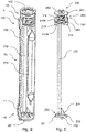
- Fig. 2 shows an isometric view with a partial cross-section of the receiver drier according to one example.
- the receiver drier 1 comprises an elongated, cylindrical housing 100.
- the housing 100 forms an internal volume with a first end 110 with an inlet 111 and a second end 120, opposite the first end 110, with an outlet 121.
- the receiver drier 1 further comprises an internal assembly 200 comprising a baffle 210 dividing the internal volume of the housing 100 so that on a first side 210a of the baffle 210 there is a first internal volume Va, and on a second side 210b of the baffle 210 there is a second internal volume Vb.
- the baffle 210 comprises a through-hole 213.
- a tube 220 is attached to the through-hole 213 in the baffle 210 from the first side 210a, so that the fluid can travel through the tube 220 from the first side 210a of the baffle 210 to the second side 210b of the baffle 210.
- the tube 220 and the baffle 210 are a single, integral part. This allows to lower the costs of the assembly.
- the inlet 111 is associated with the first internal volume Va, while the outlet 121 is associated with the second internal volume Vb.
- the receiver drier may further comprise a desiccant pouch 270 within the first volume Va.
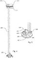
- Fig. 3 shows an example of an internal assembly 200 of the receiver drier 1.
- the tube 220 is at its first end attached to the though-hole 213 of the baffle 210, and at its second end it comprises a positioning device 230 cooperating with the housing 100.
- the receiver drier 1 may comprise a top filtering device 260 for the heat exchange fluid on the second side of the baffle 210.
- the top filtering device 260 comprises a top cover 261 supported on the baffle 210 by side legs 262, thereby creating a top filtering volume Vfa. It further comprises a top filtering mesh 263 surrounding, e.g. by being attached to the side legs 262, the top filtering volume Vfa so that the heat exchange fluid entering the top filtering volume Vfa from the tube 220 is forced to travel through the filtering mesh 263 before exiting through the outlet 121.
- the internal assembly 200 may comprise top distancing means 264 for immobilizing the internal assembly 200 with respect to the housing 100.
- the tube 220 extends eccentrically with respect to the housing 100.
- the housing 100 may have a bottom cover 102.
- the positioning device 230 is then in contact with the bottom cover 102.
- the positioning device 230 may comprise a plurality of legs 231, 232, 233 extending substantially perpendicularly from the tube 220. At least one of the legs 231, 232, 233 may have a support portion 234 extending between said leg 231, 232, 233 and the tube 220 obliquely with respect to their general axes of extension.
- the desiccant pouch 270 may then rest on the support portion 234.
- the housing may also have a top cover 103.
- the top cover 103 may be removable or permanently fixed. In case of removable top cover 103, the receiver drier and its inner parts may be subject to servicing.
- Fig. 4 shows another example of an internal assembly of the receiver drier.
- the baffle 210 may comprise a baffle spacing means 211 for distancing and/or mounting the desiccant pouch 270.
- Fig. 5 shows a closer view of one of the ends of the internal assembly of Fig. 4 .
- One or more legs 231, 231, 233 may form an arch with a spacing 235 located underneath to facilitate flow of the refrigerant within the internal volume.
- Additional protrusion 236 may be present to balance the assembly on the bottom cover 102.
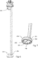
- Fig. 6 shows yet another example of an internal assembly of the receiver drier.
- the tube 220 may comprise a hook 221.
- the desiccant pouch may then be 270 attached to, e.g. hanged from, said hook 221.
- the positioning device 230 may comprise a bottom filtering device 250 for the heat exchange fluid.
- Fig. 7 shows a closer view of one of the ends of the internal assembly of Fig. 6 .
- the bottom filtering device 250 comprises a chamber 251 forming a bottom filtering volume Vfb.
- the chamber 251 has an inlet opening 252 covered with a bottom filtering mesh 253 and an outlet 254 to which the second end of the tube 220 is attached.
- the bottom filtering mesh 253 may be spread between inner protrusions 255.
- the receiver drier comprising both the top filtering device 260 and the bottom filtering device 230.
Landscapes
- Engineering & Computer Science (AREA)
- Physics & Mathematics (AREA)
- Mechanical Engineering (AREA)
- Thermal Sciences (AREA)
- General Engineering & Computer Science (AREA)
- Chemical & Material Sciences (AREA)
- Analytical Chemistry (AREA)
- Power Engineering (AREA)
- Air-Conditioning For Vehicles (AREA)
- Detail Structures Of Washing Machines And Dryers (AREA)
Abstract
Description
- The invention relates to a receiver drier for a refrigerant fluid circuit equipping a vehicle, in particular for a condenser within a motor vehicle.
- Vehicles, in particular motor vehicles, are routinely equipped with a ventilation, heating and/or climate control installation, also called an air conditioning installation. An air conditioning installation of this kind is in particular dedicated to enhancing the comfort of the passenger compartment of the vehicle. The air conditioning installation cooperates with a closed circuit through which a refrigerant fluid circulates used by a heat exchanger that the air conditioning installation comprises for thermally treating air sent into the passenger compartment.
- Successively in the direction of circulation of the refrigerant fluid through it, the refrigerant fluid circuit essentially comprises a compressor, a condenser, an expansion member and an evaporator. The refrigerant fluid in the gas phase is compressed by the compressor, transformed into the liquid phase in the condenser, expanded at low pressures by the expansion member and then transformed into the gas phase in the evaporator and routed again to the compressor.
- In this context, the refrigerant fluid circuit comprises a refrigerant fluid receiver drier disposed between the condenser and the expansion member. The receiver drier provides a reserve of refrigerant fluid guaranteeing stable operation of the refrigerant fluid circuit over time. The receiver drier may also house a particle filter to retain any particles captured by the refrigerant fluid during its circulation through the refrigerant fluid circuit. The receiver drier may further house a material that absorbs moisture contained in the refrigerant fluid, hereinafter designated the desiccant.
- The receiver drier essentially comprises a closed housing, preferably accommodating the particle filter and the desiccant. The housing is provided with a fluid inlet for admitting the refrigerant fluid to the interior of the housing and a fluid outlet for evacuating the refrigerant fluid from the housing after it has passed through the internal volume. Depending on different requirements with respect to the functions expected from the receiver drier, internal assembly may differ significantly between variants. On the other hands, there is a continuous trend regarding lowering the overall cost of the receiver drier.
- The object of the present invention is to provide a cost effective and adaptable design of the receiver drier.
- The object of the invention is, among others, a receiver drier for a condenser of a heat exchange fluid, comprising an elongated, cylindrical housing forming an internal volume with a first end with an inlet and a second end, opposite the first end, with an outlet, further comprising an internal assembly comprising a baffle dividing the internal volume of the housing so that on a first side of the baffle there is a first internal volume, and on a second side of the baffle there is a second internal volume, the baffle comprising a through-hole, a tube attached to the through-hole in the baffle from the first side, so that the fluid can travel through the tube from the first side of the baffle to the second side of the baffle, wherein the tube and the baffle are a single, integral part.
- Preferably, the inlet is associated with the first internal volume, while the outlet is associated with the second internal volume.
- Preferably, the tube is at its first end attached to the though-hole of the baffle, and at its second end it comprises a positioning device cooperating with the housing.
- Preferably, the housing has a bottom cover, the positioning device being in contact with the bottom cover.
- Preferably, the positioning device has a plurality of legs extending substantially perpendicularly from the tube.
- Preferably, at least one of the legs has a support portion extending between said leg and the tube obliquely with respect to their general axes of extension.
- Preferably, the positioning device comprises a bottom filtering device for the heat exchange fluid.
- Preferably, the bottom filtering device comprises a chamber forming a bottom filtering volume, the chamber having an inlet opening covered with a bottom filtering mesh and an outlet to which the second end of the tube is attached.
- Preferably, the receiver drier comprises a top filtering device for the heat exchange fluid on the second side of the baffle.
- Preferably, the top filtering device comprises a top cover supported on the baffle by side legs, thereby creating a top filtering volume, and further comprises a top filtering mesh surrounding the top filtering volume so that the heat exchange fluid entering the top filtering volume from the tube is forced to travel through the filtering mesh before exiting through the outlet.
- Preferably, the tube extends eccentrically with respect to the housing.
- Preferably, the receiver drier further comprises a desiccant pouch within the first volume.
- Preferably, the desiccant pouch rests on the support portion.
- Preferably, the tube comprises a hook, the desiccant pouch being attached to said hook.
- Another object of the invention is a condenser comprising a receiver drier as described.
- Examples of the invention will be apparent from and described in detail with reference to the accompanying drawings, in which:
-
Fig. 1 shows a conventional condenser with a receiver drier; -
Fig. 2 shows an isometric view with a partial cross-section of the receiver drier according to one example; -
Fig. 3 shows an example of an internal assembly of the receiver drier; -
Fig. 4 shows another example of an internal assembly of the receiver drier; -
Fig. 5 shows a closer view of one of the ends of the internal assembly ofFig. 4 ; -
Fig. 6 shows yet another example of an internal assembly of the receiver drier; -
Fig. 7 shows a closer view of one of the ends of the internal assembly ofFig. 6 . -
Fig. 1 shows aconventional condenser 2 with areceiver drier 1 according to the invention. The refrigerant is entering the heat exchanger throughinlet 3, travels through a first pass of tubes to the inlet of the receiver drier, and then exits the receiver drier and returns through a second pass of tubes. Subsequently, it exits the heat exchanger throughoutlet 4. -
Fig. 2 shows an isometric view with a partial cross-section of the receiver drier according to one example. Thereceiver drier 1 comprises an elongated,cylindrical housing 100. Thehousing 100 forms an internal volume with afirst end 110 with aninlet 111 and asecond end 120, opposite thefirst end 110, with anoutlet 121. Thereceiver drier 1 further comprises aninternal assembly 200 comprising abaffle 210 dividing the internal volume of thehousing 100 so that on afirst side 210a of thebaffle 210 there is a first internal volume Va, and on asecond side 210b of thebaffle 210 there is a second internal volume Vb. Thebaffle 210 comprises a through-hole 213. Atube 220 is attached to the through-hole 213 in thebaffle 210 from thefirst side 210a, so that the fluid can travel through thetube 220 from thefirst side 210a of thebaffle 210 to thesecond side 210b of thebaffle 210. Thetube 220 and thebaffle 210 are a single, integral part. This allows to lower the costs of the assembly. - The
inlet 111 is associated with the first internal volume Va, while theoutlet 121 is associated with the second internal volume Vb. The receiver drier may further comprise adesiccant pouch 270 within the first volume Va. -
Fig. 3 shows an example of aninternal assembly 200 of thereceiver drier 1. Thetube 220 is at its first end attached to the though-hole 213 of thebaffle 210, and at its second end it comprises apositioning device 230 cooperating with thehousing 100. - In one variant, the
receiver drier 1 may comprise atop filtering device 260 for the heat exchange fluid on the second side of thebaffle 210. Thetop filtering device 260 comprises atop cover 261 supported on thebaffle 210 byside legs 262, thereby creating a top filtering volume Vfa. It further comprises atop filtering mesh 263 surrounding, e.g. by being attached to theside legs 262, the top filtering volume Vfa so that the heat exchange fluid entering the top filtering volume Vfa from thetube 220 is forced to travel through thefiltering mesh 263 before exiting through theoutlet 121. - The
internal assembly 200 may comprise top distancing means 264 for immobilizing theinternal assembly 200 with respect to thehousing 100. - Preferably, the
tube 220 extends eccentrically with respect to thehousing 100. - The
housing 100 may have abottom cover 102. Thepositioning device 230 is then in contact with thebottom cover 102. Thepositioning device 230 may comprise a plurality oflegs tube 220. At least one of thelegs support portion 234 extending between saidleg tube 220 obliquely with respect to their general axes of extension. Thedesiccant pouch 270 may then rest on thesupport portion 234. - The housing may also have a
top cover 103. Thetop cover 103 may be removable or permanently fixed. In case of removabletop cover 103, the receiver drier and its inner parts may be subject to servicing. -
Fig. 4 shows another example of an internal assembly of the receiver drier. In this option, there is no filtering device present in the receiver drier. Thebaffle 210 may comprise a baffle spacing means 211 for distancing and/or mounting thedesiccant pouch 270. -
Fig. 5 shows a closer view of one of the ends of the internal assembly ofFig. 4 . One ormore legs Additional protrusion 236 may be present to balance the assembly on thebottom cover 102. -
Fig. 6 shows yet another example of an internal assembly of the receiver drier. Thetube 220 may comprise ahook 221. The desiccant pouch may then be 270 attached to, e.g. hanged from, saidhook 221. - The
positioning device 230 may comprise abottom filtering device 250 for the heat exchange fluid.Fig. 7 shows a closer view of one of the ends of the internal assembly ofFig. 6 . In this example, thebottom filtering device 250 comprises achamber 251 forming a bottom filtering volume Vfb. Thechamber 251 has aninlet opening 252 covered with a bottom filtering mesh 253 and anoutlet 254 to which the second end of thetube 220 is attached. The bottom filtering mesh 253 may be spread betweeninner protrusions 255. - In one example, the receiver drier comprising both the
top filtering device 260 and thebottom filtering device 230. - Other variations to the disclosed embodiments can be understood and effected by those skilled in the art in practicing the claimed invention, from a study of drawings, the disclosure, and the appended claims. The mere fact that certain measures are recited in mutually different dependent claims does not indicate that a combination of these measures cannot be used to the advantage.
Claims (15)
- Receiver drier (1) for a condenser (2) of a heat exchange fluid, comprising an elongated, cylindrical housing (100) forming an internal volume with a first end (110) with an inlet (111) and a second end (120), opposite the first end (110), with an outlet (121), further comprising an internal assembly (200) comprising a baffle (210) dividing the internal volume of the housing (100) so that on a first side (210a) of the baffle (210) there is a first internal volume (Va), and on a second side (210b) of the baffle (210) there is a second internal volume (Vb), the baffle (210) comprising a through-hole (213), a tube (220) attached to the through-hole (213) in the baffle (210) from the first side (210a), so that the fluid can travel through the tube (220) from the first side (210a) of the baffle (210) to the second side (210b) of the baffle (210), wherein the tube (220) and the baffle (210) are a single, integral part.
- Receiver drier (1) according to claim 1, wherein the inlet (111) is associated with the first internal volume (Va), while the outlet (121) is associated with the second internal volume (Vb).
- Receiver drier (1) according to any preceding claim, wherein the tube (220) is at its first end attached to the though-hole (213) of the baffle (210), and at its second end it comprises a positioning device (230) cooperating with the housing (100).
- Receiver drier (1) according to claim 3, wherein the housing (100) has a bottom cover (102), the positioning device (230) being in contact with the bottom cover (102).
- Receiver drier (1) according to claim 4, wherein the positioning device (230) has a plurality of legs (231, 232, 233) extending substantially perpendicularly from the tube (220).
- Receiver drier (1) according to claim 5, wherein at least one of the legs (231, 232, 233) has a support portion (234) extending between said leg (231, 232, 233) and the tube (220) obliquely with respect to their general axes of extension.
- Receiver drier (1) according to any of claims 3 or 4, wherein the positioning device (230) comprises a bottom filtering device (250) for the heat exchange fluid.
- Receiver drier (1) according to claim 7, wherein the bottom filtering device (250) comprises a chamber (251) forming a bottom filtering volume (Vfb), the chamber (251) having an inlet opening (252) covered with a bottom filtering mesh (253) and an outlet (254) to which the second end of the tube (220) is attached.
- Receiver drier (1) according to any preceding claim, wherein it comprises a top filtering device (260) for the heat exchange fluid on the second side of the baffle (210).
- Receiver drier (1) according to claim 9, wherein the top filtering device (260) comprises a top cover (261) supported on the baffle (210) by side legs (262), thereby creating a top filtering volume (Vfa), and further comprises a top filtering mesh (263) surrounding the top filtering volume (Vfa) so that the heat exchange fluid entering the top filtering volume (Vfa) from the tube (220) is forced to travel through the filtering mesh (263) before exiting through the outlet (121).
- Receiver drier (1) according to any preceding claim, wherein the tube (220) extends eccentrically with respect to the housing (100).
- Receiver drier (1) according to any preceding claim, wherein it further comprises a desiccant pouch (270) within the first volume (Va).
- Receiver drier (1) according to claim 6 and 12, wherein the desiccant pouch (270) rests on the support portion (234).
- Receiver drier (1) according to claim 12 or 13, wherein the tube (220) comprises a hook (221), the desiccant pouch (270) being attached to said hook (221).
- Condenser (2) comprising a receiver drier (1) according to any of the preceding claims.
Priority Applications (3)
| Application Number | Priority Date | Filing Date | Title |
|---|---|---|---|
| EP20461578.5A EP3992550B1 (en) | 2020-10-30 | 2020-10-30 | Receiver drier for a condenser |
| CN202180073821.6A CN116348719B (en) | 2020-10-30 | 2021-09-28 | For condensers liquid storage dryer |
| PCT/EP2021/076650 WO2022089861A1 (en) | 2020-10-30 | 2021-09-28 | Receiver drier for a condenser |
Applications Claiming Priority (1)
| Application Number | Priority Date | Filing Date | Title |
|---|---|---|---|
| EP20461578.5A EP3992550B1 (en) | 2020-10-30 | 2020-10-30 | Receiver drier for a condenser |
Publications (2)
| Publication Number | Publication Date |
|---|---|
| EP3992550A1 true EP3992550A1 (en) | 2022-05-04 |
| EP3992550B1 EP3992550B1 (en) | 2024-08-21 |
Family
ID=73043207
Family Applications (1)
| Application Number | Title | Priority Date | Filing Date |
|---|---|---|---|
| EP20461578.5A Active EP3992550B1 (en) | 2020-10-30 | 2020-10-30 | Receiver drier for a condenser |
Country Status (3)
| Country | Link |
|---|---|
| EP (1) | EP3992550B1 (en) |
| CN (1) | CN116348719B (en) |
| WO (1) | WO2022089861A1 (en) |
Citations (3)
| Publication number | Priority date | Publication date | Assignee | Title |
|---|---|---|---|---|
| US6381983B1 (en) * | 1999-11-10 | 2002-05-07 | Porous Media Corporation | Filter-drier with replaceable tubular filter element |
| EP2636974A1 (en) * | 2012-03-08 | 2013-09-11 | DENSO THERMAL SYSTEMS S.p.A. | A non-replaceable filter assembly for a vehicle condenser having an upper subcooling section |
| US20180135904A1 (en) * | 2016-11-15 | 2018-05-17 | Keihin Thermal Technology Corporation | Condenser |
Family Cites Families (4)
| Publication number | Priority date | Publication date | Assignee | Title |
|---|---|---|---|---|
| KR101513724B1 (en) * | 2008-08-27 | 2015-04-20 | 한라비스테온공조 주식회사 | A Structure and a Making Method for Receiver Drier Cap |
| CN101865577A (en) * | 2010-06-02 | 2010-10-20 | 和龙双昊高新技术有限公司 | Liquid storing drier plug with filter screen |
| CN206483308U (en) * | 2017-02-16 | 2017-09-12 | 常州腾兴汽车配件有限公司 | Novel energy-conserving automobile heat exchange drier receiver |
| CN207335240U (en) * | 2017-10-09 | 2018-05-08 | 博格思众(常州)热交换器有限公司 | Drier receiver and on-board air conditioner |
-
2020
- 2020-10-30 EP EP20461578.5A patent/EP3992550B1/en active Active
-
2021
- 2021-09-28 WO PCT/EP2021/076650 patent/WO2022089861A1/en not_active Ceased
- 2021-09-28 CN CN202180073821.6A patent/CN116348719B/en active Active
Patent Citations (3)
| Publication number | Priority date | Publication date | Assignee | Title |
|---|---|---|---|---|
| US6381983B1 (en) * | 1999-11-10 | 2002-05-07 | Porous Media Corporation | Filter-drier with replaceable tubular filter element |
| EP2636974A1 (en) * | 2012-03-08 | 2013-09-11 | DENSO THERMAL SYSTEMS S.p.A. | A non-replaceable filter assembly for a vehicle condenser having an upper subcooling section |
| US20180135904A1 (en) * | 2016-11-15 | 2018-05-17 | Keihin Thermal Technology Corporation | Condenser |
Also Published As
| Publication number | Publication date |
|---|---|
| CN116348719A (en) | 2023-06-27 |
| EP3992550B1 (en) | 2024-08-21 |
| WO2022089861A1 (en) | 2022-05-05 |
| CN116348719B (en) | 2026-03-10 |
Similar Documents
| Publication | Publication Date | Title |
|---|---|---|
| AU2008318222B2 (en) | A vehicle-cabin air-conditioning system and a module containing the system | |
| US9758014B2 (en) | Low profile air conditioning unit for vehicles | |
| KR101193377B1 (en) | Humidity control device | |
| JP4608834B2 (en) | Refrigeration cycle equipment | |
| US20060254310A1 (en) | Apparatus for cooling air-conditioning refrigerant | |
| CN107883618B (en) | Air reservoir valve for vehicle climate control system | |
| KR100703920B1 (en) | Condenser with integrated receiver drier | |
| JP2000227265A (en) | Recipient integrated refrigerant condenser | |
| JP7197404B2 (en) | gas-liquid separator | |
| EP3992550B1 (en) | Receiver drier for a condenser | |
| WO2020110477A1 (en) | Compact air-conditioning device | |
| JPH11190573A (en) | Gas-liquid separator | |
| WO1997033129A1 (en) | Air conditioner receiver dryer and method of making same | |
| JP2022013057A (en) | Gas-liquid separation device | |
| JP6518209B2 (en) | Refrigeration cycle | |
| JP2020003187A (en) | Gas-liquid separator | |
| US20210180843A1 (en) | Receiver/drier for a refrigerant fluid circuit equipping a vehicle, in particular a motor vehicle | |
| JP2000074527A (en) | Recipient integrated refrigerant condenser | |
| US2686406A (en) | Air conditioner | |
| WO2020110478A1 (en) | Compact air conditioner | |
| JP6606052B2 (en) | Air conditioner | |
| EP1831619B1 (en) | A cooling device | |
| JPS62276375A (en) | Refrigerator | |
| JP3978273B2 (en) | accumulator | |
| JP2579029Y2 (en) | Cooling unit for automotive air conditioner |
Legal Events
| Date | Code | Title | Description |
|---|---|---|---|
| PUAI | Public reference made under article 153(3) epc to a published international application that has entered the european phase |
Free format text: ORIGINAL CODE: 0009012 |
|
| STAA | Information on the status of an ep patent application or granted ep patent |
Free format text: STATUS: THE APPLICATION HAS BEEN PUBLISHED |
|
| AK | Designated contracting states |
Kind code of ref document: A1 Designated state(s): AL AT BE BG CH CY CZ DE DK EE ES FI FR GB GR HR HU IE IS IT LI LT LU LV MC MK MT NL NO PL PT RO RS SE SI SK SM TR |
|
| STAA | Information on the status of an ep patent application or granted ep patent |
Free format text: STATUS: REQUEST FOR EXAMINATION WAS MADE |
|
| 17P | Request for examination filed |
Effective date: 20221102 |
|
| RBV | Designated contracting states (corrected) |
Designated state(s): AL AT BE BG CH CY CZ DE DK EE ES FI FR GB GR HR HU IE IS IT LI LT LU LV MC MK MT NL NO PL PT RO RS SE SI SK SM TR |
|
| P01 | Opt-out of the competence of the unified patent court (upc) registered |
Effective date: 20230528 |
|
| GRAP | Despatch of communication of intention to grant a patent |
Free format text: ORIGINAL CODE: EPIDOSNIGR1 |
|
| STAA | Information on the status of an ep patent application or granted ep patent |
Free format text: STATUS: GRANT OF PATENT IS INTENDED |
|
| INTG | Intention to grant announced |
Effective date: 20240312 |
|
| GRAS | Grant fee paid |
Free format text: ORIGINAL CODE: EPIDOSNIGR3 |
|
| GRAA | (expected) grant |
Free format text: ORIGINAL CODE: 0009210 |
|
| STAA | Information on the status of an ep patent application or granted ep patent |
Free format text: STATUS: THE PATENT HAS BEEN GRANTED |
|
| AK | Designated contracting states |
Kind code of ref document: B1 Designated state(s): AL AT BE BG CH CY CZ DE DK EE ES FI FR GB GR HR HU IE IS IT LI LT LU LV MC MK MT NL NO PL PT RO RS SE SI SK SM TR |
|
| REG | Reference to a national code |
Ref country code: GB Ref legal event code: FG4D |
|
| REG | Reference to a national code |
Ref country code: CH Ref legal event code: EP |
|
| REG | Reference to a national code |
Ref country code: IE Ref legal event code: FG4D |
|
| REG | Reference to a national code |
Ref country code: DE Ref legal event code: R096 Ref document number: 602020036137 Country of ref document: DE |
|
| REG | Reference to a national code |
Ref country code: LT Ref legal event code: MG9D |
|
| REG | Reference to a national code |
Ref country code: NL Ref legal event code: MP Effective date: 20240821 |
|
| PG25 | Lapsed in a contracting state [announced via postgrant information from national office to epo] |
Ref country code: NO Free format text: LAPSE BECAUSE OF FAILURE TO SUBMIT A TRANSLATION OF THE DESCRIPTION OR TO PAY THE FEE WITHIN THE PRESCRIBED TIME-LIMIT Effective date: 20241121 |
|
| REG | Reference to a national code |
Ref country code: AT Ref legal event code: MK05 Ref document number: 1715839 Country of ref document: AT Kind code of ref document: T Effective date: 20240821 |
|
| PG25 | Lapsed in a contracting state [announced via postgrant information from national office to epo] |
Ref country code: FI Free format text: LAPSE BECAUSE OF FAILURE TO SUBMIT A TRANSLATION OF THE DESCRIPTION OR TO PAY THE FEE WITHIN THE PRESCRIBED TIME-LIMIT Effective date: 20240821 Ref country code: NL Free format text: LAPSE BECAUSE OF FAILURE TO SUBMIT A TRANSLATION OF THE DESCRIPTION OR TO PAY THE FEE WITHIN THE PRESCRIBED TIME-LIMIT Effective date: 20240821 Ref country code: PT Free format text: LAPSE BECAUSE OF FAILURE TO SUBMIT A TRANSLATION OF THE DESCRIPTION OR TO PAY THE FEE WITHIN THE PRESCRIBED TIME-LIMIT Effective date: 20241223 Ref country code: GR Free format text: LAPSE BECAUSE OF FAILURE TO SUBMIT A TRANSLATION OF THE DESCRIPTION OR TO PAY THE FEE WITHIN THE PRESCRIBED TIME-LIMIT Effective date: 20241122 Ref country code: PL Free format text: LAPSE BECAUSE OF FAILURE TO SUBMIT A TRANSLATION OF THE DESCRIPTION OR TO PAY THE FEE WITHIN THE PRESCRIBED TIME-LIMIT Effective date: 20240821 |
|
| PG25 | Lapsed in a contracting state [announced via postgrant information from national office to epo] |
Ref country code: BG Free format text: LAPSE BECAUSE OF FAILURE TO SUBMIT A TRANSLATION OF THE DESCRIPTION OR TO PAY THE FEE WITHIN THE PRESCRIBED TIME-LIMIT Effective date: 20240821 |
|
| PG25 | Lapsed in a contracting state [announced via postgrant information from national office to epo] |
Ref country code: LV Free format text: LAPSE BECAUSE OF FAILURE TO SUBMIT A TRANSLATION OF THE DESCRIPTION OR TO PAY THE FEE WITHIN THE PRESCRIBED TIME-LIMIT Effective date: 20240821 |
|
| PG25 | Lapsed in a contracting state [announced via postgrant information from national office to epo] |
Ref country code: AT Free format text: LAPSE BECAUSE OF FAILURE TO SUBMIT A TRANSLATION OF THE DESCRIPTION OR TO PAY THE FEE WITHIN THE PRESCRIBED TIME-LIMIT Effective date: 20240821 Ref country code: IS Free format text: LAPSE BECAUSE OF FAILURE TO SUBMIT A TRANSLATION OF THE DESCRIPTION OR TO PAY THE FEE WITHIN THE PRESCRIBED TIME-LIMIT Effective date: 20241221 |
|
| PG25 | Lapsed in a contracting state [announced via postgrant information from national office to epo] |
Ref country code: HR Free format text: LAPSE BECAUSE OF FAILURE TO SUBMIT A TRANSLATION OF THE DESCRIPTION OR TO PAY THE FEE WITHIN THE PRESCRIBED TIME-LIMIT Effective date: 20240821 |
|
| PG25 | Lapsed in a contracting state [announced via postgrant information from national office to epo] |
Ref country code: ES Free format text: LAPSE BECAUSE OF FAILURE TO SUBMIT A TRANSLATION OF THE DESCRIPTION OR TO PAY THE FEE WITHIN THE PRESCRIBED TIME-LIMIT Effective date: 20240821 Ref country code: RS Free format text: LAPSE BECAUSE OF FAILURE TO SUBMIT A TRANSLATION OF THE DESCRIPTION OR TO PAY THE FEE WITHIN THE PRESCRIBED TIME-LIMIT Effective date: 20241121 |
|
| PG25 | Lapsed in a contracting state [announced via postgrant information from national office to epo] |
Ref country code: RS Free format text: LAPSE BECAUSE OF FAILURE TO SUBMIT A TRANSLATION OF THE DESCRIPTION OR TO PAY THE FEE WITHIN THE PRESCRIBED TIME-LIMIT Effective date: 20241121 Ref country code: PT Free format text: LAPSE BECAUSE OF FAILURE TO SUBMIT A TRANSLATION OF THE DESCRIPTION OR TO PAY THE FEE WITHIN THE PRESCRIBED TIME-LIMIT Effective date: 20241223 Ref country code: PL Free format text: LAPSE BECAUSE OF FAILURE TO SUBMIT A TRANSLATION OF THE DESCRIPTION OR TO PAY THE FEE WITHIN THE PRESCRIBED TIME-LIMIT Effective date: 20240821 Ref country code: NO Free format text: LAPSE BECAUSE OF FAILURE TO SUBMIT A TRANSLATION OF THE DESCRIPTION OR TO PAY THE FEE WITHIN THE PRESCRIBED TIME-LIMIT Effective date: 20241121 Ref country code: NL Free format text: LAPSE BECAUSE OF FAILURE TO SUBMIT A TRANSLATION OF THE DESCRIPTION OR TO PAY THE FEE WITHIN THE PRESCRIBED TIME-LIMIT Effective date: 20240821 Ref country code: LV Free format text: LAPSE BECAUSE OF FAILURE TO SUBMIT A TRANSLATION OF THE DESCRIPTION OR TO PAY THE FEE WITHIN THE PRESCRIBED TIME-LIMIT Effective date: 20240821 Ref country code: IS Free format text: LAPSE BECAUSE OF FAILURE TO SUBMIT A TRANSLATION OF THE DESCRIPTION OR TO PAY THE FEE WITHIN THE PRESCRIBED TIME-LIMIT Effective date: 20241221 Ref country code: HR Free format text: LAPSE BECAUSE OF FAILURE TO SUBMIT A TRANSLATION OF THE DESCRIPTION OR TO PAY THE FEE WITHIN THE PRESCRIBED TIME-LIMIT Effective date: 20240821 Ref country code: GR Free format text: LAPSE BECAUSE OF FAILURE TO SUBMIT A TRANSLATION OF THE DESCRIPTION OR TO PAY THE FEE WITHIN THE PRESCRIBED TIME-LIMIT Effective date: 20241122 Ref country code: FI Free format text: LAPSE BECAUSE OF FAILURE TO SUBMIT A TRANSLATION OF THE DESCRIPTION OR TO PAY THE FEE WITHIN THE PRESCRIBED TIME-LIMIT Effective date: 20240821 Ref country code: ES Free format text: LAPSE BECAUSE OF FAILURE TO SUBMIT A TRANSLATION OF THE DESCRIPTION OR TO PAY THE FEE WITHIN THE PRESCRIBED TIME-LIMIT Effective date: 20240821 Ref country code: BG Free format text: LAPSE BECAUSE OF FAILURE TO SUBMIT A TRANSLATION OF THE DESCRIPTION OR TO PAY THE FEE WITHIN THE PRESCRIBED TIME-LIMIT Effective date: 20240821 Ref country code: AT Free format text: LAPSE BECAUSE OF FAILURE TO SUBMIT A TRANSLATION OF THE DESCRIPTION OR TO PAY THE FEE WITHIN THE PRESCRIBED TIME-LIMIT Effective date: 20240821 |
|
| PG25 | Lapsed in a contracting state [announced via postgrant information from national office to epo] |
Ref country code: DK Free format text: LAPSE BECAUSE OF FAILURE TO SUBMIT A TRANSLATION OF THE DESCRIPTION OR TO PAY THE FEE WITHIN THE PRESCRIBED TIME-LIMIT Effective date: 20240821 Ref country code: SM Free format text: LAPSE BECAUSE OF FAILURE TO SUBMIT A TRANSLATION OF THE DESCRIPTION OR TO PAY THE FEE WITHIN THE PRESCRIBED TIME-LIMIT Effective date: 20240821 Ref country code: RO Free format text: LAPSE BECAUSE OF FAILURE TO SUBMIT A TRANSLATION OF THE DESCRIPTION OR TO PAY THE FEE WITHIN THE PRESCRIBED TIME-LIMIT Effective date: 20240821 |
|
| PG25 | Lapsed in a contracting state [announced via postgrant information from national office to epo] |
Ref country code: EE Free format text: LAPSE BECAUSE OF FAILURE TO SUBMIT A TRANSLATION OF THE DESCRIPTION OR TO PAY THE FEE WITHIN THE PRESCRIBED TIME-LIMIT Effective date: 20240821 |
|
| PG25 | Lapsed in a contracting state [announced via postgrant information from national office to epo] |
Ref country code: CZ Free format text: LAPSE BECAUSE OF FAILURE TO SUBMIT A TRANSLATION OF THE DESCRIPTION OR TO PAY THE FEE WITHIN THE PRESCRIBED TIME-LIMIT Effective date: 20240821 |
|
| PG25 | Lapsed in a contracting state [announced via postgrant information from national office to epo] |
Ref country code: SK Free format text: LAPSE BECAUSE OF FAILURE TO SUBMIT A TRANSLATION OF THE DESCRIPTION OR TO PAY THE FEE WITHIN THE PRESCRIBED TIME-LIMIT Effective date: 20240821 Ref country code: IT Free format text: LAPSE BECAUSE OF FAILURE TO SUBMIT A TRANSLATION OF THE DESCRIPTION OR TO PAY THE FEE WITHIN THE PRESCRIBED TIME-LIMIT Effective date: 20240821 |
|
| REG | Reference to a national code |
Ref country code: DE Ref legal event code: R097 Ref document number: 602020036137 Country of ref document: DE |
|
| REG | Reference to a national code |
Ref country code: CH Ref legal event code: PL |
|
| PLBE | No opposition filed within time limit |
Free format text: ORIGINAL CODE: 0009261 |
|
| STAA | Information on the status of an ep patent application or granted ep patent |
Free format text: STATUS: NO OPPOSITION FILED WITHIN TIME LIMIT |
|
| PG25 | Lapsed in a contracting state [announced via postgrant information from national office to epo] |
Ref country code: MC Free format text: LAPSE BECAUSE OF FAILURE TO SUBMIT A TRANSLATION OF THE DESCRIPTION OR TO PAY THE FEE WITHIN THE PRESCRIBED TIME-LIMIT Effective date: 20240821 |
|
| PG25 | Lapsed in a contracting state [announced via postgrant information from national office to epo] |
Ref country code: BE Free format text: LAPSE BECAUSE OF NON-PAYMENT OF DUE FEES Effective date: 20241031 Ref country code: LU Free format text: LAPSE BECAUSE OF NON-PAYMENT OF DUE FEES Effective date: 20241030 |
|
| GBPC | Gb: european patent ceased through non-payment of renewal fee |
Effective date: 20241121 |
|
| PG25 | Lapsed in a contracting state [announced via postgrant information from national office to epo] |
Ref country code: CH Free format text: LAPSE BECAUSE OF NON-PAYMENT OF DUE FEES Effective date: 20241031 |
|
| 26N | No opposition filed |
Effective date: 20250522 |
|
| REG | Reference to a national code |
Ref country code: BE Ref legal event code: MM Effective date: 20241031 |
|
| PG25 | Lapsed in a contracting state [announced via postgrant information from national office to epo] |
Ref country code: SE Free format text: LAPSE BECAUSE OF FAILURE TO SUBMIT A TRANSLATION OF THE DESCRIPTION OR TO PAY THE FEE WITHIN THE PRESCRIBED TIME-LIMIT Effective date: 20240821 |
|
| PG25 | Lapsed in a contracting state [announced via postgrant information from national office to epo] |
Ref country code: GB Free format text: LAPSE BECAUSE OF NON-PAYMENT OF DUE FEES Effective date: 20241121 |
|
| PG25 | Lapsed in a contracting state [announced via postgrant information from national office to epo] |
Ref country code: IE Free format text: LAPSE BECAUSE OF NON-PAYMENT OF DUE FEES Effective date: 20241030 |
|
| PGFP | Annual fee paid to national office [announced via postgrant information from national office to epo] |
Ref country code: DE Payment date: 20251015 Year of fee payment: 6 |
|
| PGFP | Annual fee paid to national office [announced via postgrant information from national office to epo] |
Ref country code: FR Payment date: 20251027 Year of fee payment: 6 |
|
| PG25 | Lapsed in a contracting state [announced via postgrant information from national office to epo] |
Ref country code: HU Free format text: LAPSE BECAUSE OF FAILURE TO SUBMIT A TRANSLATION OF THE DESCRIPTION OR TO PAY THE FEE WITHIN THE PRESCRIBED TIME-LIMIT; INVALID AB INITIO Effective date: 20201030 |
|
| PG25 | Lapsed in a contracting state [announced via postgrant information from national office to epo] |
Ref country code: CY Free format text: LAPSE BECAUSE OF FAILURE TO SUBMIT A TRANSLATION OF THE DESCRIPTION OR TO PAY THE FEE WITHIN THE PRESCRIBED TIME-LIMIT; INVALID AB INITIO Effective date: 20201030 |