EP3992530A1 - Burner supply tube with fuel channel - Google Patents
Burner supply tube with fuel channel Download PDFInfo
- Publication number
- EP3992530A1 EP3992530A1 EP20204639.7A EP20204639A EP3992530A1 EP 3992530 A1 EP3992530 A1 EP 3992530A1 EP 20204639 A EP20204639 A EP 20204639A EP 3992530 A1 EP3992530 A1 EP 3992530A1
- Authority
- EP
- European Patent Office
- Prior art keywords
- tube
- burner
- supply tube
- fuel
- channel
- Prior art date
- Legal status (The legal status is an assumption and is not a legal conclusion. Google has not performed a legal analysis and makes no representation as to the accuracy of the status listed.)
- Ceased
Links
Images


Classifications
-
- F—MECHANICAL ENGINEERING; LIGHTING; HEATING; WEAPONS; BLASTING
- F23—COMBUSTION APPARATUS; COMBUSTION PROCESSES
- F23R—GENERATING COMBUSTION PRODUCTS OF HIGH PRESSURE OR HIGH VELOCITY, e.g. GAS-TURBINE COMBUSTION CHAMBERS
- F23R3/00—Continuous combustion chambers using liquid or gaseous fuel
- F23R3/28—Continuous combustion chambers using liquid or gaseous fuel characterised by the fuel supply
- F23R3/283—Attaching or cooling of fuel injecting means including supports for fuel injectors, stems, or lances
-
- F—MECHANICAL ENGINEERING; LIGHTING; HEATING; WEAPONS; BLASTING
- F23—COMBUSTION APPARATUS; COMBUSTION PROCESSES
- F23C—METHODS OR APPARATUS FOR COMBUSTION USING FLUID FUEL OR SOLID FUEL SUSPENDED IN A CARRIER GAS OR AIR
- F23C1/00—Combustion apparatus specially adapted for combustion of two or more kinds of fuel simultaneously or alternately, at least one kind of fuel being either a fluid fuel or a solid fuel suspended in a carrier gas or air
- F23C1/08—Combustion apparatus specially adapted for combustion of two or more kinds of fuel simultaneously or alternately, at least one kind of fuel being either a fluid fuel or a solid fuel suspended in a carrier gas or air liquid and gaseous fuel
-
- F—MECHANICAL ENGINEERING; LIGHTING; HEATING; WEAPONS; BLASTING
- F23—COMBUSTION APPARATUS; COMBUSTION PROCESSES
- F23D—BURNERS
- F23D11/00—Burners using a direct spraying action of liquid droplets or vaporised liquid into the combustion space
- F23D11/36—Details
- F23D11/38—Nozzles; Cleaning devices therefor
- F23D11/383—Nozzles; Cleaning devices therefor with swirl means
-
- F—MECHANICAL ENGINEERING; LIGHTING; HEATING; WEAPONS; BLASTING
- F23—COMBUSTION APPARATUS; COMBUSTION PROCESSES
- F23D—BURNERS
- F23D14/00—Burners for combustion of a gas, e.g. of a gas stored under pressure as a liquid
- F23D14/20—Non-premix gas burners, i.e. in which gaseous fuel is mixed with combustion air on arrival at the combustion zone
- F23D14/22—Non-premix gas burners, i.e. in which gaseous fuel is mixed with combustion air on arrival at the combustion zone with separate air and gas feed ducts, e.g. with ducts running parallel or crossing each other
- F23D14/24—Non-premix gas burners, i.e. in which gaseous fuel is mixed with combustion air on arrival at the combustion zone with separate air and gas feed ducts, e.g. with ducts running parallel or crossing each other at least one of the fluids being submitted to a swirling motion
-
- F—MECHANICAL ENGINEERING; LIGHTING; HEATING; WEAPONS; BLASTING
- F23—COMBUSTION APPARATUS; COMBUSTION PROCESSES
- F23R—GENERATING COMBUSTION PRODUCTS OF HIGH PRESSURE OR HIGH VELOCITY, e.g. GAS-TURBINE COMBUSTION CHAMBERS
- F23R3/00—Continuous combustion chambers using liquid or gaseous fuel
- F23R3/28—Continuous combustion chambers using liquid or gaseous fuel characterised by the fuel supply
- F23R3/36—Supply of different fuels
-
- F—MECHANICAL ENGINEERING; LIGHTING; HEATING; WEAPONS; BLASTING
- F23—COMBUSTION APPARATUS; COMBUSTION PROCESSES
- F23R—GENERATING COMBUSTION PRODUCTS OF HIGH PRESSURE OR HIGH VELOCITY, e.g. GAS-TURBINE COMBUSTION CHAMBERS
- F23R2900/00—Special features of, or arrangements for continuous combustion chambers; Combustion processes therefor
- F23R2900/00001—Arrangements using bellows, e.g. to adjust volumes or reduce thermal stresses
Definitions
- the invention is about a burner supply tube a part of a burner arrangement, wherein a fluid could be guided within the burner supply tube to a burner.
- the burner supply tube comprises additionally an integrated fuel channel.
- a common burner arrangement for a usage within a combustion section of a gas turbine comprises at first at least on burner.
- the burner itself is arranged on the upstream side of a combustion chamber, wherein a fuel is burned with combustion air.
- the burners - in regard to the invention - are able to operate with two different kind of fuels. Therefore, it is necessary to provide the burner arrangement with two different fuel supplies.
- a known solution comprises three coaxially tubes arranged upstream of the burner. Through the center a first fuel - regular a gaseous fuel - and through an annular channel between the center tube and the middle tube the combustion air could be supplied to the burner.
- the outer tube is usually used as protection of the upstream side of the burner arrangement.
- As second fuel in frequent cases a liquid fuel is used. Therefore, the cross section to supply the liquid fuel could be significantly lower than the cross section necessary to supply the gaseous fuel.
- the common solution comprises a fuel pipe arranged parallel to the arrangement of tubes to guide the liquid fuel to the burner.
- the task for the invention is the design on an improved solution to supply the burner with a liquid fuel parallel to an arrangement of coaxially tubes for a gaseous fuel and for combustion air.
- the generic burner supply tube comprises at first a tube wall extending from an upstream end to a downstream end and has a substantially cylindrical shape.
- the burner supply tube defines a tube length from the upstream end to the downstream end and further a tube diameter as the dimension of the outer side of the tube wall.
- the tube length is at least 2 times and at most 20 times the tube diameter.
- the burner supply tube is a hollow part with a substantially thin tube wall, wherein the tube wall has a wall thickness, which is at least 0,01 times and at most 0,2 times the tube diameter.
- the burner supply tube further comprises at least one integrated fuel channel extending along the tube wall. Necessarily the fuel channel starts at a fuel input and leads to a fuel output.
- the fuel input is not necessarily located directly at the upstream end but needs to be arranged at least in the edge area near the upstream end.
- Analogous the fuel output is arranged at the downstream end within the edge area of the downstream end or immediately at the downstream end.
- the burner supply tube has not necessarily a free upstream end and/or a free downstream end. As part of a burner arrangement further components would be rather arranged at the upstream end and/or at the downstream end of the burner supply tube.
- an equivalent diameter of the fuel channel should not be less than 0,3 times the wall thickness of the tube wall.
- the diameter of the circular shape is the equivalent diameter of the fuel channel. Otherwise the equivalent diameter could be calculated by the determination of the cross section of the fuel channel.
- the size of the fuel channel should not exceed a certain limit. (Obviously in the state of the art with integrated fuel channels inside the tube wall the diameter of the fuel channels must be less than the thickness of the tube wall.)
- the equivalent diameter of the fuel channel should not exceed 3 times the wall thickness of the tube wall.
- the fuel channel is now designed in the form of a helix. It is not necessary, that the fuel channel comprises the helical shape from the fuel input to the fuel output, but at least along the majority of the tube length the fuel channel needs to have a helical design with a gradient of at least 0,5 times and at most 5 times the tube diameter.
- the size of the fuel channel could be increased as a thickening at the outer side and/or at the inner side of the burner supply tube due to the fuel channel could be allowed. Even with the thickening a thermal stress on the component, does - due to the helical shape - not lead to an undetermined deformation or an unallowable thermal stress inside the tube wall. Regular this is a major problem if the fuel channel with a bigger size is in a straight line along the tube wall and different thermal expansion occur within the tube wall at the fuel channel and beside the fuel channel. Next, a thickening at the tube wall due to the fuel channel could influence the fluid stream inside and/or outside the burner supply tube in a positive way, as a swirl could be added to the fluid stream.
- the burner supply tube comprises certain relative dimensions. Therefore, it is advantageous if the tube length is at least 4 times and/or at most 10 times the tube diameter. It is also advantageous if the wall thickness is at least 0,02 times and/or at most 0,1 times the tube diameter. As result the tube wall has the shape of a tube in a common sense.
- the fuel channel has advantageously an equivalent diameter of at least 0,6 times the wall thickness.
- These leads not necessarily but usually - to a thickening on the outer side and/or on the inner side of the tube wall.
- the thickening with the helical shape does not hinder the usability of the solution, but the increase of the size of the fuel channel the supply of a liquid fuel through a single (each of or the one) fuel channel could be improved.
- the size of the fuel channel should not be oversized compared to the thickness of the tube wall.
- the equivalent diameter is at most 1,5 times the wall thickness.
- the helical section of the fuel channel has a certain shape in regard of the size of the burner supply tube.
- the gradient of the fuel channel is at least 1 time and/or at most 2,5 times the tube diameter. Within this range the best results with respect to thermal stress could be achieved.
- the fuel channel is an integrated feature of the burner supply tube and therefore needs to be arranged at or within the tube wall. Even it is possible to arrange the fuel channel at the outer side or at the inner side of the tube wall it is advantageous, if at least the center of the fuel channel is arranged within the outer side and the inner side of the tube wall (without the fuel channel). It is in particular advantageous if the center of the fuel channel is arranged between the middle and the inner side of the tube wall.
- the thickness should not be more than necessary.
- the local thickness of the burner supply tube at the fuel channel is advantageously at most 3 times the equivalent diameter of the fuel channel.
- Analogous the local thickness of the burner supply tube at the fuel channel is advantageously at most 3 times the wall thickness of the tube wall.
- the inventive burner supply tube enables the design of a new inventive burner arrangement, which is intentionally used in a combustion section.
- the burner arrangement comprises at first a burner, which is intentionally arranged upstream of a combustion chamber of the combustion section.
- the generic solution comprises a tube arrangement arranged upstream of the burner.
- This tube arrangement comprises an outer protection tube at the outer side of the tube arrangement.
- a burner supply tube is necessary.
- a first inner fluid supply tube is arranged.
- an outer annular space is arranged between the outer protection tube and the burner supply tube.
- On the inner side of the burner supply tube between this and the first inner supply tube a second annular space is available.
- the tube arrangement comprises a further second inner fluid supply tube arranged inside the first inner fluid supply tube creating a further annular space between the both inner fluid supply tubes.
- An improved possibility to supply the burner with a liquid fuel is enabled with the inventive burner arrangement, which makes use of the inventive burner supply tube and enables a beneficial guidance of a liquid fuel through the fuel channel within the burner supply tube from the upstream side of the tube arrangement to the burner at the downstream side of the tube arrangement.
- a first possibility is to fit the downstream end of one or more of the tubes in respective sleeves of the burner. To guarantee a safe guidance of fuel and combustion air to the burner separate from each other and to enable a fixed position of the tube arrangement relative to the burner it is advantageous if the outer protection tube is firmly connected with the burner.
- the burner supply tube could be arranged movable within a sleeve of the burner. But analogous it is advantageous to connect the burner supply tube with the burner in a firmly manner. The same applies for the first fluid supply tube and if existing also for the second fluid supply tube. It is in particular advantageous if all tubes of the tube arrangement are connected firmly with the burner.
- the burner arrangement comprises advantageously a terminal block.
- This terminal block is arranged upstream of the tube arrangement and enables on the upstream side the attachment of other means.
- the terminal block is firmly connected to the burner supply tube.
- Analog, a mounted or a welded or an integral solution is possible.
- the outer protection tube is also firmly connected to the terminal block.
- the outer protection tube comprises some bellows.
- a fluid tight connection between one of the inner tubes with the terminal block is requested, but less important than at the outer tube.
- a connection between the first fluid supply tube and the terminal block respectively between the second fluid supply tube and the terminal block is provided, which enables a relative thermal expansion, for example by fitting the upstream end of the fluid supply tube within a sleeve.
- the arrangement of the first fluid supply tube within the burner supply tube leads to an annular free space, which is used advantageously as an annular fluid channel to guide a - in particular gaseous - fuel or combustion gas to the burner. Therefore, it is advantageous if the width - the distance between the inner side of the burner supply tube and the outer side of the first fluid supply tube - of the annular fluid channel is at least 0,05 times the tube diameter.
- the advantage usage of the first supply tube to guide further medium, e.g. a gaseous fuel or combustion gas, inside the first supply tube could be achieved, if the width of the annular fluid channel is preferred not more than 0,3 times the tube diameter.
- the width of the annular fluid channel is at least 0,1 times the tube diameter and/or at most 0,2 times the tube diameter.
- the thickening on the inner side of the burner supply tube is at least 0,2 times the width of the annular fluid channel.
- the thickening on the inner side of the burner supply tube is at most 0,7 times the width of the annular channel. It is in particular advantageous, if the height of the thickening the inner side is at least 0,3 times and/or at most 0,6 times the width of the annular channel.
- exemplary tube arrangement 31 located between a burner 32 at the downstream end and a terminal block at the upstream end 03 is shown in a longitudinal section.
- the tube arrangement 31 comprises at the outer side and outer protection tube 33 which 33 is firmly connected with the burner 32 on the downstream side 04 and also firmly connected to the terminal block at the upstream end 03.
- the outer protection tube 33 comprises a bellow. Further the mounting frame is attached with further bellows in-between with the outer protection tube 33.
- the exemplary burner supply tube 01 is arranged. This 01 is also firmly connected with the burner 32 on the downstream end 04 and with the terminal block at the upstream end 03.
- the burner supply tube 01 comprises an integrated fuel channel 11, which has almost of the length helical shape.
- first fluid supply tube 34 is arranged inside the burner supply tube 01 . This is also firmly connected with the burner 32. To prevent terminal stress the first fluid supply tube 34 is connected with the terminal end at the upstream end 03 with the ability of terminal expansion. Between the burner supply tube 01 and the first fluid supply tube 34 in annular channel is defined.
- a further second fluid supply tube 35 is arranged inside the first fluid supply tube 34 . This leads to the possibility to guide a further medium from the upstream end 03 to the burner 32 at the downstream end 04.
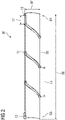
- FIG 2 the exemplary burner supply tube 01 used in the tube arrangement 31 of figure 1 is shown, wherein in figure 3 a detail on the fuel channel is sketched.
- the burner supply tube 01 comprises a thin tube wall 05 with the tube length 06 and the tube diameter 07, which is the diameter on the outer side of the tube wall 05.
- the tube length 06 is in this example about 4 times the tube diameter 07.
- the tube wall 05 is quite thin compared to the size of the burner supply tube 01 and has the tube thickness 08 of about 0,05 times the tube diameter 07.
- the burner supply tube 01 comprises as key feature the fuel channel 11. This has a fuel input 12 at the upstream end 03 and a fuel output 13 at the downstream end 04 (the fuel output 13 is offset in circumferential direction and therefore not directly visible in this section). After a short distance of 17 from the fuel output 13 and analogue after a short distance from the fuel input 12 the fuel channel 11 comprises the helical shape with the gradient 14. In this example the gradient 14 of the fuel channel 11 is about 1,5 times the tube diameter 07.
- the integration of the fuel channel 11 inside the burner supply tube 01 leads to the necessity to arrange thickening 15, 16 in this case on the inner side and on the outer side of the tube wall 05.
- the inner thickening 16 leads to a decrease of the distance the first supply tube 34. Due to the helical shape of the fuel channel 11 the inner thickening 16 does not hinder the fluid stream inside the annular fuel channel.
- the fuel channel 11 is arranged with its center in a radial direction at the inner side of the tube wall 05. This leads to a smaller outer thickening 15 on the outer side of the tube wall 05 and the higher thickening 16 on the inner side of the tube wall 05.
Landscapes
- Engineering & Computer Science (AREA)
- Chemical & Material Sciences (AREA)
- Combustion & Propulsion (AREA)
- Mechanical Engineering (AREA)
- General Engineering & Computer Science (AREA)
- Gas Burners (AREA)
- Pre-Mixing And Non-Premixing Gas Burner (AREA)
Abstract
The invention is about a burner supply tube (01) and a burner arrangement comprising such a burner supply tube (01). The burner supply tube (01) comprises a tube wall (05) having a tube diameter (07) and at least one integrated fuel channel (11) extending from a fuel input (12) at an upstream end (03) to a fuel output (13) at a downstream end (04). To enable an integrated design the fuel channel (11) is along the majority of the tube length (06) helical with a gradient (14) of at least 0,5 times and at most 5 times the tube diameter (07).
Description
- The invention is about a burner supply tube a part of a burner arrangement, wherein a fluid could be guided within the burner supply tube to a burner. To enable a further supply with a fuel the burner supply tube comprises additionally an integrated fuel channel.
- A common burner arrangement for a usage within a combustion section of a gas turbine comprises at first at least on burner. The burner itself is arranged on the upstream side of a combustion chamber, wherein a fuel is burned with combustion air. The burners - in regard to the invention - are able to operate with two different kind of fuels. Therefore, it is necessary to provide the burner arrangement with two different fuel supplies. A known solution comprises three coaxially tubes arranged upstream of the burner. Through the center a first fuel - regular a gaseous fuel - and through an annular channel between the center tube and the middle tube the combustion air could be supplied to the burner. The outer tube is usually used as protection of the upstream side of the burner arrangement. As second fuel in frequent cases a liquid fuel is used. Therefore, the cross section to supply the liquid fuel could be significantly lower than the cross section necessary to supply the gaseous fuel. As result the common solution comprises a fuel pipe arranged parallel to the arrangement of tubes to guide the liquid fuel to the burner.
- Even the usage of a fuel pipe is a common and easy solution, there are some problems remaining, as the thermal displacement and further the sealing of the burner arrangement needs to be considered. Therefore, further solutions try to integrate the fuel channel into one of the tubes as straight-line bore inside the wall of the tube. To prevent an increase of the thickness of the respective tube, generally several bores with a smaller diameter are used to replace a single pipe arranged outside of the tubes.
- The task for the invention is the design on an improved solution to supply the burner with a liquid fuel parallel to an arrangement of coaxially tubes for a gaseous fuel and for combustion air.
- The task is solved by a burner supply tube according to claim 1. A burner arrangement having such a burner supply tube is given in claim 7. Further advantageous solutions are subject of the dependent claims.
- The generic burner supply tube comprises at first a tube wall extending from an upstream end to a downstream end and has a substantially cylindrical shape.
Thereby the burner supply tube defines a tube length from the upstream end to the downstream end and further a tube diameter as the dimension of the outer side of the tube wall. Here, the tube length is at least 2 times and at most 20 times the tube diameter. Further, the burner supply tube is a hollow part with a substantially thin tube wall, wherein the tube wall has a wall thickness, which is at least 0,01 times and at most 0,2 times the tube diameter. - To enable the supply of a liquid fuel along the burner supply tube, the burner supply tube further comprises at least one integrated fuel channel extending along the tube wall. Necessarily the fuel channel starts at a fuel input and leads to a fuel output. Here, the fuel input is not necessarily located directly at the upstream end but needs to be arranged at least in the edge area near the upstream end. Analogous the fuel output is arranged at the downstream end within the edge area of the downstream end or immediately at the downstream end.
- It must be noted that the burner supply tube has not necessarily a free upstream end and/or a free downstream end. As part of a burner arrangement further components would be rather arranged at the upstream end and/or at the downstream end of the burner supply tube. To determine the burner supply tube with the upstream end and the downstream end in the sense of this invention of the tube wall and the fuel input and the fuel output needs to be considered. If the upstream end or the downstream end could not be determined obviously by the shape of the tube wall comprising the fuel input close to the upstream end respectively the fuel output close to the downstream end, the upstream end is 0,25 times the tube diameter upstream the fuel input and analogous the downstream end is 0,25 times the tube diameter downstream the fuel output.
- It should be possible to supply fuel, in particular a liquid fuel, through the fuel channel to the burner. Therefore, an equivalent diameter of the fuel channel should not be less than 0,3 times the wall thickness of the tube wall.
- Obviously, if the fuel channel has a circular shape, the diameter of the circular shape is the equivalent diameter of the fuel channel. Otherwise the equivalent diameter could be calculated by the determination of the cross section of the fuel channel.
- To arrange the fuel channel integrated into the burner supply tube the size of the fuel channel should not exceed a certain limit. (Obviously in the state of the art with integrated fuel channels inside the tube wall the diameter of the fuel channels must be less than the thickness of the tube wall.) Here, to enable the arrangement of the fuel channel at the burner supply tube the equivalent diameter of the fuel channel should not exceed 3 times the wall thickness of the tube wall.
- To enable the increase of the diameter of the fuel channel and to prohibit an uncontrollable deformation of the burner supply tube by a thermal displacement the fuel channel is now designed in the form of a helix. It is not necessary, that the fuel channel comprises the helical shape from the fuel input to the fuel output, but at least along the majority of the tube length the fuel channel needs to have a helical design with a gradient of at least 0,5 times and at most 5 times the tube diameter.
- At first benefit the size of the fuel channel could be increased as a thickening at the outer side and/or at the inner side of the burner supply tube due to the fuel channel could be allowed. Even with the thickening a thermal stress on the component, does - due to the helical shape - not lead to an undetermined deformation or an unallowable thermal stress inside the tube wall. Regular this is a major problem if the fuel channel with a bigger size is in a straight line along the tube wall and different thermal expansion occur within the tube wall at the fuel channel and beside the fuel channel. Next, a thickening at the tube wall due to the fuel channel could influence the fluid stream inside and/or outside the burner supply tube in a positive way, as a swirl could be added to the fluid stream.
- The most benefit could be archived by the inventive solution if the burner supply tube comprises certain relative dimensions. Therefore, it is advantageous if the tube length is at least 4 times and/or at most 10 times the tube diameter. It is also advantageous if the wall thickness is at least 0,02 times and/or at most 0,1 times the tube diameter. As result the tube wall has the shape of a tube in a common sense.
- To arrange the fuel channel with the helical shape at the tube wall and to make use of an optimized size of the fuel channel it is in particular advantageous to arrange only one fuel channel or just two fuel channels arranged opposite to each other at the burner supply tube. It could be still advantageous to make use of three fuel channels arranged offset in circumference direction. But with each additional channel the benefit of the inventive solution decreases with an approach to common solutions.
- Next with the burner supply tube a beneficial supply of a liquid fuel could be archived, it the fuel channel has advantageously an equivalent diameter of at least 0,6 times the wall thickness. These leads - not necessarily but usually - to a thickening on the outer side and/or on the inner side of the tube wall. As explained before, the thickening with the helical shape does not hinder the usability of the solution, but the increase of the size of the fuel channel the supply of a liquid fuel through a single (each of or the one) fuel channel could be improved.
- On the other hand, the size of the fuel channel should not be oversized compared to the thickness of the tube wall. Here, it is advantageous if the equivalent diameter is at most 1,5 times the wall thickness.
- To prevent unallowable thermal stress inside the burner supply tube and to prevent uncontrollable thermal deformation it is further advantageous if the helical section of the fuel channel has a certain shape in regard of the size of the burner supply tube. Here, it is advantageous if the gradient of the fuel channel is at least 1 time and/or at most 2,5 times the tube diameter. Within this range the best results with respect to thermal stress could be achieved.
- Obviously, it makes less sense to arrange the fuel input or the fuel output at the inner side of the tube wall as the connection the next component upstream (fuel input) or downstream (fuel output) is more difficult. As result an arrangement of the fuel input at the upstream end with an opening to the upstream side and also an arrangement of the fuel output at the downstream end with an opening to the downstream side is possible. But it is preferred to arrange the fuel input and/or the fuel output on the outer side of the tube wall of the burner supply tube. This could simplify the connection to the fuel input respectively to the fuel output if the attached component embraces the upstream end respectively the downstream end of the burner supply tube.
- The fuel channel is an integrated feature of the burner supply tube and therefore needs to be arranged at or within the tube wall. Even it is possible to arrange the fuel channel at the outer side or at the inner side of the tube wall it is advantageous, if at least the center of the fuel channel is arranged within the outer side and the inner side of the tube wall (without the fuel channel). It is in particular advantageous if the center of the fuel channel is arranged between the middle and the inner side of the tube wall.
- To guarantee a sufficient stability of the burner supply tube at the position of the fuel channel it is advantageous to increase the thickness of the tube wall in that certain area.
- Therefore, a local thickening on the outer side of the tube wall and/or on the inner side of the tube wall at the position of the fuel channel is advantageous.
- But on the other hand, the thickness should not be more than necessary. Thereby the local thickness of the burner supply tube at the fuel channel is advantageously at most 3 times the equivalent diameter of the fuel channel. Analogous the local thickness of the burner supply tube at the fuel channel is advantageously at most 3 times the wall thickness of the tube wall.
- The inventive burner supply tube enables the design of a new inventive burner arrangement, which is intentionally used in a combustion section. In principle it is possible to use the burner arrangement at different kind of combustion system, but it is advantageous to use the solution at a combustion section of a gas turbine. The burner arrangement comprises at first a burner, which is intentionally arranged upstream of a combustion chamber of the combustion section. To supply the burner with different kind of fuel and combustion air the generic solution comprises a tube arrangement arranged upstream of the burner. This tube arrangement comprises an outer protection tube at the outer side of the tube arrangement. Next inside the outer protection tube a burner supply tube is necessary. Within the burner supply tube, a first inner fluid supply tube is arranged. As result an outer annular space is arranged between the outer protection tube and the burner supply tube. On the inner side of the burner supply tube between this and the first inner supply tube a second annular space is available.
- In a further advantageous solution, the tube arrangement comprises a further second inner fluid supply tube arranged inside the first inner fluid supply tube creating a further annular space between the both inner fluid supply tubes.
- Which of the annular spaces is used to guide a fuel, in particular a gaseous fuel, and which is used to guide the combustion air is not relevant here.
- An improved possibility to supply the burner with a liquid fuel is enabled with the inventive burner arrangement, which makes use of the inventive burner supply tube and enables a beneficial guidance of a liquid fuel through the fuel channel within the burner supply tube from the upstream side of the tube arrangement to the burner at the downstream side of the tube arrangement.
- At first it is not relevant how the tube arrangement and the burner is connected. A first possibility is to fit the downstream end of one or more of the tubes in respective sleeves of the burner. To guarantee a safe guidance of fuel and combustion air to the burner separate from each other and to enable a fixed position of the tube arrangement relative to the burner it is advantageous if the outer protection tube is firmly connected with the burner.
- Here, it is possible to mount the outer protection tube at the burner. A further option is a solution, where both parts are welded or brazed to each other. As a third option is an integral solution.
- Also, the burner supply tube could be arranged movable within a sleeve of the burner. But analogous it is advantageous to connect the burner supply tube with the burner in a firmly manner. The same applies for the first fluid supply tube and if existing also for the second fluid supply tube. It is in particular advantageous if all tubes of the tube arrangement are connected firmly with the burner.
- To enable the fitting of further pipes and channels to the tube arrangement the burner arrangement comprises advantageously a terminal block. This terminal block is arranged upstream of the tube arrangement and enables on the upstream side the attachment of other means.
- To achieve a fluid tight connection and a defined position of the terminal block relative to the tube arrangement advantageously the terminal block is firmly connected to the burner supply tube. Analog, a mounted or a welded or an integral solution is possible.
- It is further advantageous, if the outer protection tube is also firmly connected to the terminal block. To avoid unallowable thermal stress due to different thermal expansion of the burner supply tube and the outer protection tube it is in particular advantageous, if the outer protection tube comprises some bellows.
- A fluid tight connection between one of the inner tubes with the terminal block is requested, but less important than at the outer tube. To avoid thermal stress at the first fluid supply tube and/or the second fluid supply tube preferably a connection between the first fluid supply tube and the terminal block respectively between the second fluid supply tube and the terminal block is provided, which enables a relative thermal expansion, for example by fitting the upstream end of the fluid supply tube within a sleeve.
- The arrangement of the first fluid supply tube within the burner supply tube leads to an annular free space, which is used advantageously as an annular fluid channel to guide a - in particular gaseous - fuel or combustion gas to the burner. Therefore, it is advantageous if the width - the distance between the inner side of the burner supply tube and the outer side of the first fluid supply tube - of the annular fluid channel is at least 0,05 times the tube diameter. The advantage usage of the first supply tube to guide further medium, e.g. a gaseous fuel or combustion gas, inside the first supply tube could be achieved, if the width of the annular fluid channel is preferred not more than 0,3 times the tube diameter. Here, it is particular advantageous if the width of the annular fluid channel is at least 0,1 times the tube diameter and/or at most 0,2 times the tube diameter.
- If a thickening on the inner side of the burner supply tube is given, obviously the distance to the first fluid supply tube is decreased locally at the position of the fluid channel. As the fluid channel comprises a helical shape, the thickening could have a beneficial effect on the fluid stream inside the annular fluid channel. Therefore, it is advantageous, if the thickening on the inner side of the burner supply tube is at least 0,2 times the width of the annular fluid channel. On the other side there should be a free space left from the thickening to the first fluid supply tube. Therefore, it is advantageous, if the thickening on the inner side of the burner supply tube is at most 0,7 times the width of the annular channel. It is in particular advantageous, if the height of the thickening the inner side is at least 0,3 times and/or at most 0,6 times the width of the annular channel.
- In the following figures an example of an inventive tube arrangement with an inventive burner supply tube is shown:
- Fig. 1
- shows an example of a tube arrangement in longitudinal section;
- Fig. 2
- shows the exemplary inventive burner supply tube;
- Fig. 3
- shows in detail the fuel channel of the burner supply tube.
- In
figure 1 exemplary tube arrangement 31 located between aburner 32 at the downstream end and a terminal block at theupstream end 03 is shown in a longitudinal section. Thetube arrangement 31 comprises at the outer side andouter protection tube 33 which 33 is firmly connected with theburner 32 on thedownstream side 04 and also firmly connected to the terminal block at theupstream end 03. To prevent terminal stress inside thetube arrangement 31 theouter protection tube 33 comprises a bellow. Further the mounting frame is attached with further bellows in-between with theouter protection tube 33. - Next to the
outer protection tube 33 the exemplaryburner supply tube 01 is arranged. This 01 is also firmly connected with theburner 32 on thedownstream end 04 and with the terminal block at theupstream end 03. Theburner supply tube 01 comprises an integratedfuel channel 11, which has almost of the length helical shape. - Inside the
burner supply tube 01 firstfluid supply tube 34 is arranged. This is also firmly connected with theburner 32. To prevent terminal stress the firstfluid supply tube 34 is connected with the terminal end at theupstream end 03 with the ability of terminal expansion. Between theburner supply tube 01 and the firstfluid supply tube 34 in annular channel is defined. - In this example inside the first fluid supply tube 34 a further second
fluid supply tube 35 is arranged. This leads to the possibility to guide a further medium from theupstream end 03 to theburner 32 at thedownstream end 04. - In
figure 2 the exemplaryburner supply tube 01 used in thetube arrangement 31 offigure 1 is shown, wherein infigure 3 a detail on the fuel channel is sketched. Theburner supply tube 01 comprises athin tube wall 05 with thetube length 06 and thetube diameter 07, which is the diameter on the outer side of thetube wall 05. Thetube length 06 is in this example about 4 times thetube diameter 07. Thetube wall 05 is quite thin compared to the size of theburner supply tube 01 and has thetube thickness 08 of about 0,05 times thetube diameter 07. - The
burner supply tube 01 comprises as key feature thefuel channel 11. This has afuel input 12 at theupstream end 03 and afuel output 13 at the downstream end 04 (thefuel output 13 is offset in circumferential direction and therefore not directly visible in this section). After a short distance of 17 from thefuel output 13 and analogue after a short distance from thefuel input 12 thefuel channel 11 comprises the helical shape with thegradient 14. In this example thegradient 14 of thefuel channel 11 is about 1,5 times thetube diameter 07. - The integration of the
fuel channel 11 inside theburner supply tube 01 leads to the necessity to arrange thickening 15, 16 in this case on the inner side and on the outer side of thetube wall 05. Theinner thickening 16 leads to a decrease of the distance thefirst supply tube 34. Due to the helical shape of thefuel channel 11 theinner thickening 16 does not hinder the fluid stream inside the annular fuel channel. In this example it is preferred that thefuel channel 11 is arranged with its center in a radial direction at the inner side of thetube wall 05. This leads to a smaller outer thickening 15 on the outer side of thetube wall 05 and thehigher thickening 16 on the inner side of thetube wall 05.
Claims (12)
- Burner supply tube (01) with a tube wall (05) extending from an upstream end (03) to a downstream end (04) along a tube length (06) further having a tube diameter (07) and a wall thickness (08), wherein the tube length (06) is at least 2 times and at most 20 times the tube diameter (07) and the wall thickness (08) is at least 0,01 times and at most 0,2 times the tube diameter (07), comprising at least one integrated fuel channel (11) extending from a fuel input (12) at the upstream end (03) to a fuel output (13) at the downstream end (04), wherein the fuel channel (11) has an equivalent diameter of at least 0,3 times and at most 3 times the wall thickness (08),
characterized in that
the fuel channel (11) is along the majority of the tube length (06) helical with a gradient (14) of at least 0,5 times and at most 5 times the tube diameter (07). - Burner supply tube (01) according to claim 1,
wherein the tube length (06) is at least 4 times and/or at most 10 times the tube diameter (07); and/or
wherein the wall thickness (08) is at least 0,02 times and/or at most 0,1 times the tube diameter (07). - Burner supply tube (01) according to claim 1 or 2 comprising one or two fuel channels (11); and/or
wherein the equivalent diameter is at least 0,6 times and/or at most 1,5 times the wall thickness (08); and/or wherein the gradient (14) is at least 1 times and/or at most 2,5 times the tube diameter (07). - Burner supply tube (01) according to one of the claims 1 to 3,
wherein the distance from a fuel input to the helical form and from a fuel output to the helical form is at most 1 time, in particular at most 0,5 times, the tube diameter (07). - Burner supply tube (01) according to one of the claims 1 to 4,
wherein the fuel input (12) and/or the fuel output (13) are arranged on the outer side of the burner supply tube (01) . - Burner supply tube according to one of the claims 1 to 5, wherein the fuel channel (11) is arranged with its center between the middle and the inner side of the tube wall (05) .
- Burner supply tube according to one of the claims 1 to 6, wherein a thickening (15, 16) due to the fuel channel (11) is arranged on the inner side and/or on the outer side of the tube wall (05).
- Burner supply tube according to claim 7,
wherein a local thickness of the burner supply tube (01) at the fuel channel is at most 3 times the equivalent diameter; and/or
wherein a local thickness of the burner supply tube (01) at the fuel channel is at most 3 times the wall thickness (08) . - Burner arrangement having a burner (32) and a tube arrangement (31), which (31) is attached to the burner (32) at its upstream side and which (31) is comprising- an outer protection tube (33) and- a first inner fluid supply tube (34) and- in particular a second inner fluid supply tube (35) and- a burner supply tube (01) according to one of the preceding claims arranged between the protection tube (33) and first fluid supply tube (34).
- Burner arrangement according to claim 9,
wherein the outer protection tube (33) is firmly connected with the burner (32), and in particular firmly connected with an mounting frame, and firmly connected at the upstream end with a terminal block and comprises bellows; and/or
wherein the burner supply tube (01) is firmly connected to the burner (32) and firmly connected at the upstream end with a terminal block; and/or
wherein the first fluid supply tube (34) and/or second fluid supply tube (35) is/are firmly connected with the burner (32) while a thermal expansion is possible at the upstream end at a terminal block. - Burner arrangement according to claim 9 or 10,
wherein an annular fluid channel is defined between the burner supply tube (01) and first fluid supply tube (34) with a channel width between the burner supply tube (01) and first fluid supply tube (34), wherein the channel width is at least 0,05 times and at most 0,3 times, in particular at least 0,1 times and at most 0,2 times, the tube diameter (07). - Burner arrangement according to one of the claims 9 to 11,
wherein the local distance from the first fluid supply tube (34) to a thickening at the fuel channel is at least 0,2 times and at most 0,7 times, in particular at least 0,3 times and at most 0,6 times, the channel width.
Priority Applications (6)
| Application Number | Priority Date | Filing Date | Title |
|---|---|---|---|
| EP20204639.7A EP3992530A1 (en) | 2020-10-29 | 2020-10-29 | Burner supply tube with fuel channel |
| PCT/EP2021/072330 WO2022089804A1 (en) | 2020-10-29 | 2021-08-11 | Burner supply tube with fuel channel |
| US18/032,179 US12305851B2 (en) | 2020-10-29 | 2021-08-11 | Burner supply tube with fuel channel |
| ES21762409T ES2989799T3 (en) | 2020-10-29 | 2021-08-11 | Burner arrangement with burner supply tube with fuel channel |
| EP21762409.7A EP4204737B1 (en) | 2020-10-29 | 2021-08-11 | Burner arrangement with burner supply tube with fuel channel |
| CN202180074363.8A CN116368331B (en) | 2020-10-29 | 2021-08-11 | Burner supply pipe with fuel passage |
Applications Claiming Priority (1)
| Application Number | Priority Date | Filing Date | Title |
|---|---|---|---|
| EP20204639.7A EP3992530A1 (en) | 2020-10-29 | 2020-10-29 | Burner supply tube with fuel channel |
Publications (1)
| Publication Number | Publication Date |
|---|---|
| EP3992530A1 true EP3992530A1 (en) | 2022-05-04 |
Family
ID=73039863
Family Applications (2)
| Application Number | Title | Priority Date | Filing Date |
|---|---|---|---|
| EP20204639.7A Ceased EP3992530A1 (en) | 2020-10-29 | 2020-10-29 | Burner supply tube with fuel channel |
| EP21762409.7A Active EP4204737B1 (en) | 2020-10-29 | 2021-08-11 | Burner arrangement with burner supply tube with fuel channel |
Family Applications After (1)
| Application Number | Title | Priority Date | Filing Date |
|---|---|---|---|
| EP21762409.7A Active EP4204737B1 (en) | 2020-10-29 | 2021-08-11 | Burner arrangement with burner supply tube with fuel channel |
Country Status (5)
| Country | Link |
|---|---|
| US (1) | US12305851B2 (en) |
| EP (2) | EP3992530A1 (en) |
| CN (1) | CN116368331B (en) |
| ES (1) | ES2989799T3 (en) |
| WO (1) | WO2022089804A1 (en) |
Citations (4)
| Publication number | Priority date | Publication date | Assignee | Title |
|---|---|---|---|---|
| US20110289842A1 (en) * | 2010-05-26 | 2011-12-01 | Exxonmobil Research And Engineering Company | Corrosion Resistant Gasifier Components |
| CN204841739U (en) * | 2015-06-02 | 2015-12-09 | 山东华一检测有限公司 | Condenser pipe |
| US20160186663A1 (en) * | 2014-12-30 | 2016-06-30 | General Electric Company | Pilot nozzle in gas turbine combustor |
| US20190186749A1 (en) * | 2017-12-18 | 2019-06-20 | General Electric Company | Premixed pilot nozzle for gas turbine combustor |
Family Cites Families (7)
| Publication number | Priority date | Publication date | Assignee | Title |
|---|---|---|---|---|
| FR2532043B1 (en) | 1982-08-23 | 1987-12-24 | Fonderie Soc Gen De | EXTRUDE TUBULAR CONDENSER |
| JP2007162998A (en) * | 2005-12-13 | 2007-06-28 | Kawasaki Heavy Ind Ltd | Fuel spray system for gas turbine engine |
| EP2489939A1 (en) * | 2011-02-18 | 2012-08-22 | Siemens Aktiengesellschaft | Combustion chamber with a wall section and a brim element |
| US9897321B2 (en) * | 2015-03-31 | 2018-02-20 | Delavan Inc. | Fuel nozzles |
| US10385809B2 (en) * | 2015-03-31 | 2019-08-20 | Delavan Inc. | Fuel nozzles |
| US10132500B2 (en) * | 2015-10-16 | 2018-11-20 | Delavan Inc. | Airblast injectors |
| EP3290804A1 (en) * | 2016-08-31 | 2018-03-07 | Siemens Aktiengesellschaft | A burner with fuel and air supply incorporated in a wall of the burner |
-
2020
- 2020-10-29 EP EP20204639.7A patent/EP3992530A1/en not_active Ceased
-
2021
- 2021-08-11 CN CN202180074363.8A patent/CN116368331B/en active Active
- 2021-08-11 ES ES21762409T patent/ES2989799T3/en active Active
- 2021-08-11 EP EP21762409.7A patent/EP4204737B1/en active Active
- 2021-08-11 WO PCT/EP2021/072330 patent/WO2022089804A1/en not_active Ceased
- 2021-08-11 US US18/032,179 patent/US12305851B2/en active Active
Patent Citations (4)
| Publication number | Priority date | Publication date | Assignee | Title |
|---|---|---|---|---|
| US20110289842A1 (en) * | 2010-05-26 | 2011-12-01 | Exxonmobil Research And Engineering Company | Corrosion Resistant Gasifier Components |
| US20160186663A1 (en) * | 2014-12-30 | 2016-06-30 | General Electric Company | Pilot nozzle in gas turbine combustor |
| CN204841739U (en) * | 2015-06-02 | 2015-12-09 | 山东华一检测有限公司 | Condenser pipe |
| US20190186749A1 (en) * | 2017-12-18 | 2019-06-20 | General Electric Company | Premixed pilot nozzle for gas turbine combustor |
Non-Patent Citations (1)
| Title |
|---|
| DATABASE WPI Week 201601, Derwent World Patents Index; AN 2015-82439M, XP002802639 * |
Also Published As
| Publication number | Publication date |
|---|---|
| EP4204737B1 (en) | 2024-06-26 |
| US12305851B2 (en) | 2025-05-20 |
| EP4204737A1 (en) | 2023-07-05 |
| WO2022089804A1 (en) | 2022-05-05 |
| EP4204737C0 (en) | 2024-06-26 |
| CN116368331A (en) | 2023-06-30 |
| ES2989799T3 (en) | 2024-11-27 |
| CN116368331B (en) | 2025-10-28 |
| US20230392783A1 (en) | 2023-12-07 |
Similar Documents
| Publication | Publication Date | Title |
|---|---|---|
| CN101784841B (en) | gas turbine burner | |
| US9435262B2 (en) | Fuel nozzle having an inner tube and an outer tube engaged with the inner tube | |
| US6256995B1 (en) | Simple low cost fuel nozzle support | |
| JP4272451B2 (en) | Apparatus for placing an igniter in a liner port of a gas turbine engine | |
| US6775984B2 (en) | Full cooling of main injectors in a two-headed combustion chamber | |
| GB2488694A (en) | Fuel Injector Feed Arm with Central Secondary Fuel Flow Passage | |
| US20120145273A1 (en) | Multiple circuit fuel manifold | |
| EP0543215A1 (en) | Sensor for determining the dielectric constant or the resistivity of a flowing liquid | |
| EP4204737B1 (en) | Burner arrangement with burner supply tube with fuel channel | |
| JP6506743B2 (en) | Fuel piping configuration of common rail fuel supply system | |
| US9772054B2 (en) | Concentric flexible hose assembly | |
| US20070042307A1 (en) | Premix burner arrangement for operating a combustion chamber and method for operating a combustion chamber | |
| US6843233B2 (en) | Fuel injection system | |
| US9958093B2 (en) | Flexible hose assembly with multiple flow passages | |
| EP3617599A1 (en) | Burner with improved air-fuel mixing | |
| US2439257A (en) | Fuel atomizing nozzle | |
| US12196420B2 (en) | Connecting apparatus for the flow connection between a fuel feed line system and a nozzle apparatus, nozzle apparatus and gas turbine arrangement | |
| US2595566A (en) | Universal pipe connection for spill burners | |
| US20240027070A1 (en) | Nozzle device for feeding at least one gaseous fuel and one liquid fuel, set, supply line system, and gas turbine assembly | |
| US10591165B2 (en) | Fuel nozzle body | |
| ITMI20012784A1 (en) | IMPROVED LIQUID FUEL INJECTOR FOR GAS TURBINE BURNERS | |
| CN119617470A (en) | Burner assembly and combustion chamber comprising said burner assembly | |
| GB1135411A (en) | Improvements in or relating to fuel burners | |
| EP3336341A1 (en) | Fuel rail assembly with a constrictor element and fuel delivery assembly | |
| US20260098641A1 (en) | Pilot arrangement, nozzle device, production method, and gas turbine arrangement |
Legal Events
| Date | Code | Title | Description |
|---|---|---|---|
| PUAI | Public reference made under article 153(3) epc to a published international application that has entered the european phase |
Free format text: ORIGINAL CODE: 0009012 |
|
| STAA | Information on the status of an ep patent application or granted ep patent |
Free format text: STATUS: THE APPLICATION HAS BEEN PUBLISHED |
|
| AK | Designated contracting states |
Kind code of ref document: A1 Designated state(s): AL AT BE BG CH CY CZ DE DK EE ES FI FR GB GR HR HU IE IS IT LI LT LU LV MC MK MT NL NO PL PT RO RS SE SI SK SM TR |
|
| RAP3 | Party data changed (applicant data changed or rights of an application transferred) |
Owner name: SIEMENS ENERGY GLOBAL GMBH & CO. KG |
|
| STAA | Information on the status of an ep patent application or granted ep patent |
Free format text: STATUS: THE APPLICATION HAS BEEN REFUSED |
|
| 18R | Application refused |
Effective date: 20220522 |