EP3992496A1 - Electromechanical actuator with no-back system - Google Patents
Electromechanical actuator with no-back system Download PDFInfo
- Publication number
- EP3992496A1 EP3992496A1 EP21205097.5A EP21205097A EP3992496A1 EP 3992496 A1 EP3992496 A1 EP 3992496A1 EP 21205097 A EP21205097 A EP 21205097A EP 3992496 A1 EP3992496 A1 EP 3992496A1
- Authority
- EP
- European Patent Office
- Prior art keywords
- ball screw
- actuator
- static disk
- drive shaft
- disk
- Prior art date
- Legal status (The legal status is an assumption and is not a legal conclusion. Google has not performed a legal analysis and makes no representation as to the accuracy of the status listed.)
- Granted
Links
Images










Classifications
-
- F—MECHANICAL ENGINEERING; LIGHTING; HEATING; WEAPONS; BLASTING
- F16—ENGINEERING ELEMENTS AND UNITS; GENERAL MEASURES FOR PRODUCING AND MAINTAINING EFFECTIVE FUNCTIONING OF MACHINES OR INSTALLATIONS; THERMAL INSULATION IN GENERAL
- F16H—GEARING
- F16H25/00—Gearings comprising primarily only cams, cam-followers and screw-and-nut mechanisms
- F16H25/18—Gearings comprising primarily only cams, cam-followers and screw-and-nut mechanisms for conveying or interconverting oscillating or reciprocating motions
- F16H25/20—Screw mechanisms
- F16H25/22—Screw mechanisms with balls, rollers, or similar members between the co-operating parts; Elements essential to the use of such members
- F16H25/2204—Screw mechanisms with balls, rollers, or similar members between the co-operating parts; Elements essential to the use of such members with balls
-
- F—MECHANICAL ENGINEERING; LIGHTING; HEATING; WEAPONS; BLASTING
- F16—ENGINEERING ELEMENTS AND UNITS; GENERAL MEASURES FOR PRODUCING AND MAINTAINING EFFECTIVE FUNCTIONING OF MACHINES OR INSTALLATIONS; THERMAL INSULATION IN GENERAL
- F16D—COUPLINGS FOR TRANSMITTING ROTATION; CLUTCHES; BRAKES
- F16D41/00—Freewheels or freewheel clutches
- F16D41/06—Freewheels or freewheel clutches with intermediate wedging coupling members between an inner and an outer surface
-
- B—PERFORMING OPERATIONS; TRANSPORTING
- B64—AIRCRAFT; AVIATION; COSMONAUTICS
- B64C—AEROPLANES; HELICOPTERS
- B64C13/00—Control systems or transmitting systems for actuating flying-control surfaces, lift-increasing flaps, air brakes, or spoilers
- B64C13/24—Transmitting means
- B64C13/26—Transmitting means without power amplification or where power amplification is irrelevant
- B64C13/28—Transmitting means without power amplification or where power amplification is irrelevant mechanical
-
- F—MECHANICAL ENGINEERING; LIGHTING; HEATING; WEAPONS; BLASTING
- F16—ENGINEERING ELEMENTS AND UNITS; GENERAL MEASURES FOR PRODUCING AND MAINTAINING EFFECTIVE FUNCTIONING OF MACHINES OR INSTALLATIONS; THERMAL INSULATION IN GENERAL
- F16D—COUPLINGS FOR TRANSMITTING ROTATION; CLUTCHES; BRAKES
- F16D55/00—Brakes with substantially-radial braking surfaces pressed together in axial direction, e.g. disc brakes
-
- F—MECHANICAL ENGINEERING; LIGHTING; HEATING; WEAPONS; BLASTING
- F16—ENGINEERING ELEMENTS AND UNITS; GENERAL MEASURES FOR PRODUCING AND MAINTAINING EFFECTIVE FUNCTIONING OF MACHINES OR INSTALLATIONS; THERMAL INSULATION IN GENERAL
- F16D—COUPLINGS FOR TRANSMITTING ROTATION; CLUTCHES; BRAKES
- F16D59/00—Self-acting brakes, e.g. coming into operation at a predetermined speed
-
- F—MECHANICAL ENGINEERING; LIGHTING; HEATING; WEAPONS; BLASTING
- F16—ENGINEERING ELEMENTS AND UNITS; GENERAL MEASURES FOR PRODUCING AND MAINTAINING EFFECTIVE FUNCTIONING OF MACHINES OR INSTALLATIONS; THERMAL INSULATION IN GENERAL
- F16D—COUPLINGS FOR TRANSMITTING ROTATION; CLUTCHES; BRAKES
- F16D65/00—Parts or details
- F16D65/02—Braking members; Mounting thereof
- F16D65/028—Rollers
-
- F—MECHANICAL ENGINEERING; LIGHTING; HEATING; WEAPONS; BLASTING
- F16—ENGINEERING ELEMENTS AND UNITS; GENERAL MEASURES FOR PRODUCING AND MAINTAINING EFFECTIVE FUNCTIONING OF MACHINES OR INSTALLATIONS; THERMAL INSULATION IN GENERAL
- F16H—GEARING
- F16H25/00—Gearings comprising primarily only cams, cam-followers and screw-and-nut mechanisms
- F16H25/18—Gearings comprising primarily only cams, cam-followers and screw-and-nut mechanisms for conveying or interconverting oscillating or reciprocating motions
- F16H25/20—Screw mechanisms
- F16H25/24—Elements essential to such mechanisms, e.g. screws, nuts
- F16H25/2454—Brakes; Rotational locks
-
- F—MECHANICAL ENGINEERING; LIGHTING; HEATING; WEAPONS; BLASTING
- F16—ENGINEERING ELEMENTS AND UNITS; GENERAL MEASURES FOR PRODUCING AND MAINTAINING EFFECTIVE FUNCTIONING OF MACHINES OR INSTALLATIONS; THERMAL INSULATION IN GENERAL
- F16H—GEARING
- F16H35/00—Gearings or mechanisms with other special functional features
- F16H2035/005—Gearings or mechanisms preventing back-driving
Definitions
- Actuators are commonly used to control and drive motion. Two common types of actuators are a hydraulic actuator and an electromechanical actuator. Typically, hydraulic actuators are preferred over electromechanical actuators in applications that involve driving heavy loads at a relatively high rate of speed. However, in certain applications, it can be desirable to drive heavy loads at high rates of speed with electromechanical actuation. In such applications, an electromechanical ball screw type actuator may be used. The pitch of a ball screw actuator can be adjusted to drive loads at faster rates of speed, however back driving forces can then become a challenge. In some applications, it is very important that large back driving forces are resisted even if the motor that drives the actuator fails.
- Various no-backing systems have been developed to account for back driving forces. An example of a ball screw system with a no-back device is disclosed in United States Patent No. 6,109,415 to Morgan et al. filed on May 29, 1998 . Improved actuation systems are desired.
- the present disclosure provides a compact, efficient, and reliable electromechanical actuator that is capable of driving heavy loads at a high rate of speed and also capable of resisting large back driving forces.
- the actuator resists tension and compression back driving forces in a static state as well as when the actuator extends and retracts. The back driving forces are resisted even if the electronics (e.g., motor) fail.
- the actuator of the depicted embodiment can be used in a wide range of applications.
- One example application for the actuator of the present disclosure is to extend and retract flaps on a wing of an airplane.
- the actuator in this example context must be able to drive large forces at a relatively high rate of speed.
- the back driving forces from the airflow across the wings can be substantial. It should be appreciated that many other applications and configurations are possible.
- the principles of the present disclosure are incorporated into a ball screw type electromechanical actuator 60.
- the actuator 60 includes a motor 62 that drives a gear box 64 within a housing 26.
- a ball screw drive shaft 14 extends into the housing 26 and is driven to rotate about its longitudinal axis by the gear box 64. Rotation of the ball screw drive shaft 14 about its longitudinal axis linearly drives the nut 66 along the ball screw drive shaft 14.
- the object being actuated e.g., flaps of an aircraft wing
- certain aspects of the present disclosure are applicable to actuators that are not considered to be a ball screw type actuator.
- the nut 66 when the ball screw drive shaft 14 is rotated in a first direction, the nut 66 is driven extending away from the housing 26. When the ball screw drive shaft 14 is rotated in a second direction, the nut 66 is retracted.
- the back driving force e.g., air pressure on the flaps
- the back driving force can apply either a tension force on the ball screw drive shaft 14 (force acting in the direction to extend the actuator 60) or a compression force on the ball screw drive shaft 14 (force acting in the direction to retract the actuator 60).
- the system of the present disclosure is configured to resist the back driving force.
- the system is configured such that the back driving force can be resisted without electrical power.
- the ball screw drive shaft 14 holds its position despite external forces acting on the ball screw drive shaft 14.
- Table 1 identifies and describes six of the operational scenarios depicted in FIG. 2 .
- Table 1 State Back Driving Forces Motor Operation Condition 1 See FIG. 2 (down the Y-axis) Compressive Static Left side of the no-back system is engaged and holds position Condition 2 See FIG. 2 (up the Y-axis) Tension Static Right side of the no-back system is engaged and holds position Condition 3 See FIG. 2 (lower left quadrant) Compressive Retract Left side of the no-back system is engaged; Motor overcomes the friction on the left side of the no-back system and the actuator retracts Condition 4 See FIG.
- the operating condition 1 is described in further detail.
- the left side (second side) of the no-back system 10 is engaged and holds the position of the actuator 60.
- the right side (first side) of the no-back system 10 is disengaged.
- the radially extending ball screw flange 12 is biased towards the left due to the external compressive back driving load on the ball screw drive shaft 14.
- the nut 66 rotates and the ball screw translates.
- the ball screw flange 12 presses against the first compression skewed roller assembly 16 which is positioned between the radially extending ball screw flange 12 and the second static disk first compression skewed roller engagement surface 18 of the second static disk 20.
- the second static disk sprag clutch engagement cylindrical surface 22 of the second static disk 20 is engaged with the second sprag clutch 24.
- the second sprag clutch 24 is orientated to resist relative rotation of the second static disk 20 and the housing 26 in the clockwise direction (second direction) and allows free relative rotation of the second static disk 20 and the housing 26 in the counterclockwise direction (first direction).
- the second static disk second compression skewed roller engagement surface 28 is driven against the second compression skewed roller assembly 30.
- the second compression skewed roller assembly 30 is driven against the second disk member 32 which is splined to the second end portion 34 of the ball screw drive shaft 14 and configured to rotate with the ball screw drive shaft 14.
- the second disk member 32 bottoms out on a bearing assembly (e.g., thrust bearing) 36, which backs up against the housing 26.
- the clutch could instead be any one-way clutch (e.g., drawn cup roller clutch, etc.) or another selective braking mechanism.
- the left side of the no-back system 10 is compressed by the compressive load and resists the back driving external force that would otherwise cause the actuator 60 to retract.
- the resistance of the back driving force does not depend on the motor or electrical system being functional.
- the failure mode for this system is that it holds the position of the actuator 60 even if a compressive external back driving force is applied to the system. It should be appreciated that many other alternative configurations are also possible.
- the operating condition 2 is described in further detail.
- the right side (first side) of the no-back system 10 is engaged and holds the position of the actuator 60.
- the left side (second side) of the no-back system 10 is disengaged.
- the radially extending ball screw flange 12 is biased towards the right due to the external tension back driving load on the ball screw drive shaft 14. It should be appreciated that many other alternative configurations are also possible.
- the ball screw flange 12 presses against the first tension skewed roller assembly 40, which is positioned between the radially extending ball screw flange 12 and the first static disk first tension skewed roller engagement surface 42 of the first static disk 44.
- the first static disk sprag clutch engagement cylindrical surface 46 of the first static disk 44 is engaged with the first sprag clutch 48.
- the first sprag clutch 48 is orientated to resist relative rotation of the first static disk 44 and the housing 26 in the counterclockwise direction (first direction) and allows free relative rotation of the first static disk 44 and the housing 26 in the clockwise direction (second direction).
- the first static disk second tension skewed roller engagement surface 50 is driven against the second tension skewed roller assembly 52.
- the second tension skewed roller assembly 52 is driven against the first disk member 54, which is splined to the second end portion 34 of the ball screw drive shaft 14 and configured to rotate with the ball screw drive shaft 14.
- the first disk member 54 bottoms out on a bearing assembly (e.g., thrust bearing) 56, which backs up against the housing 26.
- a bearing assembly e.g., thrust bearing
- the right side of the no-back system 10 is under compression imparted by the back driving tension load.
- the system is configured to resist the back driving external force that would otherwise cause the actuator 60 to extend.
- the resistance of the back driving force does not depend on the motor or electrical system being functional.
- the failure mode for this system is that it holds the position of the actuator 60 even if a compressive external back driving force is applied to the system. It should be appreciated that many other alternative configurations are also possible.
- the operating condition 3 is described in further detail.
- the back driving force is compressive and the motor 62 is driven to retract the actuator 60.
- the left side of the no-back system 10 is engaged and the right side of the no-back system 10 is disengaged.
- the motor 62 overcomes the friction on the left side of the no-back system 10 and the actuator 60 retracts. It should be appreciated that many other alternative configurations are also possible.
- the operating condition 4 is described in further detail.
- the back driving force is compressive and the motor 62 is driven to retract.
- the motor 62 overcomes the compressive back driving force.
- the right side of the no-back system 10 is not engaged, and the left side of the no-back system 10 is locked in that the first and second compression skewed rollers 16, 30 are engaged with the second static disk 20 and the second disk member 32.
- the second sprag clutch 24 allows for free rotation in the counterclockwise direction (first direction) and resists rotation in the clockwise direction (second direction).
- the ball screw driving direction is counterclockwise (first direction), therefore the no-back system 10 does not resist the motor 62. It should be appreciated that many other alternative configurations are also possible.
- the operating condition 5 is described in further detail.
- the back driving force results in tension and the motor 62 is driven clockwise to retract.
- the motor 62 overcomes the tension back driving force, and the left side of the no-back system 10 is not engaged.
- the right side of the no-back system 10 is locked in that the first and second tension skewed roller assemblies 40, 52 are engaged but the first sprag clutch 48 allows free rotation in the clockwise direction (second direction), and the actuator 60 retracts without resistance from the no-back system 10 as the ball screw drive shaft 14 rotates in the clockwise direction to drive retraction.
- the actuator 60 retracts without resistance from the no-back system 10 as the ball screw drive shaft 14 rotates in the clockwise direction to drive retraction.
- the operating condition 6 is described in further detail.
- the back driving force results in tension and the motor 62 is driven counterclockwise to drive extension.
- the right side of the no-back system 10 is engaged.
- the motor 62 overcomes the friction on the right side of the no-back system 10 to drive the extension. It should be appreciated that many other alternative configurations are also possible.
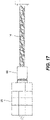
- FIGS. 16-20 additional drawings of the actuator 60 described above are shown. Like reference numbers are used to describe like features. As such, these additional figures are not additionally described herein.
- the actuator screw has a longer lead. Accordingly, the actuator is configured to move at a higher rate of speed.
- the internal no-back assembly is configured to have increased torque resisting capabilities.
- the no-back assembly has many of the same features of the no-back system described above. As such, the like components share the same reference numbers.
- the actuator includes auxiliary first and second skewed rollers 70, 74 and auxiliary first and second disks 72, 76.
- auxiliary first and second disks 72, 76 are splined or otherwise configured to rotate (or not rotate) with the first and second static disks 44, 20.
- the auxiliary first and second skewed rollers 70, 74 selectively provide friction between the first and second static disks 44, 20 and the first and second disk members 54, 32. It should be appreciated that any number of additional disks can be added to further increase the torque resistance of the no-back assembly to accommodate faster lead screws.
Landscapes
- Engineering & Computer Science (AREA)
- General Engineering & Computer Science (AREA)
- Mechanical Engineering (AREA)
- Automation & Control Theory (AREA)
- Aviation & Aerospace Engineering (AREA)
- Transmission Devices (AREA)
Abstract
Description
- This application claims the benefit of
Indian Provisional Patent Application No. 202011046739, filed on October 27, 2020 - Actuators are commonly used to control and drive motion. Two common types of actuators are a hydraulic actuator and an electromechanical actuator. Typically, hydraulic actuators are preferred over electromechanical actuators in applications that involve driving heavy loads at a relatively high rate of speed. However, in certain applications, it can be desirable to drive heavy loads at high rates of speed with electromechanical actuation. In such applications, an electromechanical ball screw type actuator may be used. The pitch of a ball screw actuator can be adjusted to drive loads at faster rates of speed, however back driving forces can then become a challenge. In some applications, it is very important that large back driving forces are resisted even if the motor that drives the actuator fails. Various no-backing systems have been developed to account for back driving forces. An example of a ball screw system with a no-back device is disclosed in
United States Patent No. 6,109,415 to Morgan et al. filed on May 29, 1998 . Improved actuation systems are desired. - The present disclosure provides a compact, efficient, and reliable electromechanical actuator that is capable of driving heavy loads at a high rate of speed and also capable of resisting large back driving forces. The actuator resists tension and compression back driving forces in a static state as well as when the actuator extends and retracts. The back driving forces are resisted even if the electronics (e.g., motor) fail.
- The following drawings are illustrative of particular embodiments of the present disclosure and therefore do not limit the scope of the present disclosure. The drawings are not to scale and are intended for use in conjunction with the explanations in the following detailed description. Embodiments of the present disclosure will hereinafter be described in conjunction with the appended drawings, wherein like numerals denote like elements.
-
FIG. 1 is an isometric view of an embodiment of the actuator according to the principles of the present disclosure; -
FIG. 2 identifies a number of possible operating scenarios of the actuator according to the principles of the present disclosure; -
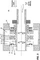
FIG. 3 is a cross-section of the actuator of the present disclosure in condition 1 where there exists a compressive back driving load and no motor applied load; -
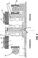
FIG. 4 is an enlarged portion ofFIG. 3 ; -
FIG. 5 is a cross-section of the actuator of the present disclosure in condition 2 where there exists a tension back driving load and no motor applied load; -
FIG. 6 is an enlarged portion ofFIG. 5 ; -
FIG. 7 is a cross-section of the actuator of the present disclosure in condition 3 where there exists a compressive back driving load and the actuator is driven to retract; -
FIG. 8 is an enlarged portion ofFIG. 7 ; -
FIG. 9 is a cross-section of the actuator of the present disclosure in condition 4 where there exists a compressive back driving load and the actuator is driven to extend; -
FIG. 10 is an enlarged portion ofFIG. 9 ; -
FIG. 11 is a cross-section of the actuator of the present disclosure in condition 5 where there exists a tension back driving load and the actuator is driven to retract; -
FIG. 12 is an enlarged portion ofFIG. 11 ; -
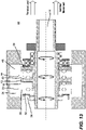
FIG. 13 is a cross-section of the actuator of the present disclosure in condition 6 where there exists a tension back driving load and the actuator is driven to extend; -
FIG. 14 is an enlarged portion ofFIG. 13 ; -
FIG. 15 is an exploded assembly view of a portion of the actuator ofFIG. 1 ; -
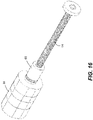
FIGS. 16-20 are additional line drawings of the actuator according to the principles of the present disclosure; and -
FIG. 21 is a cross-section of an alternative embodiment of an actuator according to the principles of the present disclosure. - Corresponding reference characters indicate corresponding parts throughout the several views. The exemplifications set out herein illustrate embodiments of the invention, and such exemplifications are not to be construed as limiting the scope of the invention in any manner.
- Reference will now be made in detail to embodiments of the present disclosure, examples of which are described herein and illustrated in the accompanying drawings. While the invention will be described in conjunction with embodiments, it will be understood that they are not intended to limit the invention to these embodiments. On the contrary, the invention is intended to cover alternatives, modifications, and equivalents, which may be included within the spirit and scope of the invention as defined by the appended claims.
- The actuator of the depicted embodiment can be used in a wide range of applications. One example application for the actuator of the present disclosure is to extend and retract flaps on a wing of an airplane. The actuator in this example context must be able to drive large forces at a relatively high rate of speed. The back driving forces from the airflow across the wings can be substantial. It should be appreciated that many other applications and configurations are possible.
- It is desirable to resist these back driving forces so that the flaps maintain their position even if there is a failure in the system (e.g., a failure of the electrical motor). In the context of an actuator that controls the position of flaps on an aircraft, it is better that the flaps fail to move as directed but hold their position than fail to move as directed and also fail to hold their position. It should be appreciated that many other applications are possible.
- Referring to
FIG. 1 , in the depicted embodiment, the principles of the present disclosure are incorporated into a ball screw typeelectromechanical actuator 60. In the depicted embodiment, theactuator 60 includes amotor 62 that drives agear box 64 within ahousing 26. A ballscrew drive shaft 14 extends into thehousing 26 and is driven to rotate about its longitudinal axis by thegear box 64. Rotation of the ballscrew drive shaft 14 about its longitudinal axis linearly drives thenut 66 along the ballscrew drive shaft 14. The object being actuated (e.g., flaps of an aircraft wing) is connected to thenut 66. It should be appreciated that certain aspects of the present disclosure are applicable to actuators that are not considered to be a ball screw type actuator. - In the depicted embodiment, when the ball
screw drive shaft 14 is rotated in a first direction, thenut 66 is driven extending away from thehousing 26. When the ballscrew drive shaft 14 is rotated in a second direction, thenut 66 is retracted. - It should be appreciated that the back driving force (e.g., air pressure on the flaps) can apply either a tension force on the ball screw drive shaft 14 (force acting in the direction to extend the actuator 60) or a compression force on the ball screw drive shaft 14 (force acting in the direction to retract the actuator 60). Regardless of the direction, the system of the present disclosure is configured to resist the back driving force. The system is configured such that the back driving force can be resisted without electrical power. In the event the electronics fail, the ball
screw drive shaft 14 holds its position despite external forces acting on the ballscrew drive shaft 14. - Table 1 identifies and describes six of the operational scenarios depicted in
FIG. 2 .Table 1 State Back Driving Forces Motor Operation Condition 1 See FIG. 2 (down the Y-axis)Compressive Static Left side of the no-back system is engaged and holds position Condition 2 See FIG. 2 (up the Y-axis)Tension Static Right side of the no-back system is engaged and holds position Condition 3 See FIG. 2 (lower left quadrant)Compressive Retract Left side of the no-back system is engaged; Motor overcomes the friction on the left side of the no-back system and the actuator retracts Condition 4 See FIG. 2 (lower right quadrant)Compressive Extend Motor overcomes the compressive back driving force; right side of the no-back system is not engaged; left side of the no-back system is locked but the sprag allows free rotation; actuator extends Condition 5 See FIG. 2 (upper left quadrant)Tension Retract Motor overcomes the tension back driving force; left side of the no-back system is not engaged; right side of the no-back system is locked but the sprag allows free rotation; actuator retracts Condition 6 See FIG. 2 (upper right quadrant)Tension Extend Right side of the no-back system is engaged; Motor overcomes the friction on the right side of the no-back system and the actuator extends - Referring to
FIGS. 3-4 , the operating condition 1 is described in further detail. In the depicted embodiment and operating condition, the left side (second side) of the no-back system 10 is engaged and holds the position of theactuator 60. The right side (first side) of the no-back system 10 is disengaged. As shown inFIG. 3 , the radially extendingball screw flange 12 is biased towards the left due to the external compressive back driving load on the ballscrew drive shaft 14. It should be appreciated that many other alternative configurations are also possible. For example, in an alternative configuration, thenut 66 rotates and the ball screw translates. - In the depicted embodiment, the
ball screw flange 12 presses against the first compression skewedroller assembly 16 which is positioned between the radially extendingball screw flange 12 and the second static disk first compression skewed roller engagement surface 18 of the secondstatic disk 20. The second static disk sprag clutch engagement cylindrical surface 22 of the secondstatic disk 20 is engaged with thesecond sprag clutch 24. Thesecond sprag clutch 24 is orientated to resist relative rotation of the secondstatic disk 20 and thehousing 26 in the clockwise direction (second direction) and allows free relative rotation of the secondstatic disk 20 and thehousing 26 in the counterclockwise direction (first direction). The second static disk second compression skewed roller engagement surface 28 is driven against the second compression skewedroller assembly 30. The second compression skewedroller assembly 30 is driven against thesecond disk member 32 which is splined to the second end portion 34 of the ballscrew drive shaft 14 and configured to rotate with the ballscrew drive shaft 14. Thesecond disk member 32 bottoms out on a bearing assembly (e.g., thrust bearing) 36, which backs up against thehousing 26. It should be appreciated that many other alternative configurations are also possible. For example, the clutch could instead be any one-way clutch (e.g., drawn cup roller clutch, etc.) or another selective braking mechanism. - In the depicted embodiment, the left side of the no-back system 10 is compressed by the compressive load and resists the back driving external force that would otherwise cause the
actuator 60 to retract. In the depicted embodiment, the resistance of the back driving force does not depend on the motor or electrical system being functional. Hence, the failure mode for this system is that it holds the position of theactuator 60 even if a compressive external back driving force is applied to the system. It should be appreciated that many other alternative configurations are also possible. - Referring to
FIGS. 5-6 , the operating condition 2 is described in further detail. In the depicted embodiment and operating condition, the right side (first side) of the no-back system 10 is engaged and holds the position of theactuator 60. The left side (second side) of the no-back system 10 is disengaged. As shown inFIG. 5 , the radially extendingball screw flange 12 is biased towards the right due to the external tension back driving load on the ballscrew drive shaft 14. It should be appreciated that many other alternative configurations are also possible. - In the depicted embodiment, the
ball screw flange 12 presses against the first tension skewedroller assembly 40, which is positioned between the radially extendingball screw flange 12 and the first static disk first tension skewed roller engagement surface 42 of the firststatic disk 44. The first static disk sprag clutch engagement cylindrical surface 46 of the firststatic disk 44 is engaged with thefirst sprag clutch 48. Thefirst sprag clutch 48 is orientated to resist relative rotation of the firststatic disk 44 and thehousing 26 in the counterclockwise direction (first direction) and allows free relative rotation of the firststatic disk 44 and thehousing 26 in the clockwise direction (second direction). The first static disk second tension skewed roller engagement surface 50 is driven against the second tension skewedroller assembly 52. The second tension skewedroller assembly 52 is driven against thefirst disk member 54, which is splined to the second end portion 34 of the ballscrew drive shaft 14 and configured to rotate with the ballscrew drive shaft 14. Thefirst disk member 54 bottoms out on a bearing assembly (e.g., thrust bearing) 56, which backs up against thehousing 26. It should be appreciated that many other alternative configurations are also possible. - In the depicted embodiment, the right side of the no-back system 10 is under compression imparted by the back driving tension load. The system is configured to resist the back driving external force that would otherwise cause the
actuator 60 to extend. In the depicted embodiment, the resistance of the back driving force does not depend on the motor or electrical system being functional. Hence, the failure mode for this system is that it holds the position of theactuator 60 even if a compressive external back driving force is applied to the system. It should be appreciated that many other alternative configurations are also possible. - Referring to
FIGS. 7-8 , the operating condition 3 is described in further detail. In the depicted embodiment and operating condition, the back driving force is compressive and themotor 62 is driven to retract theactuator 60. In this operating condition, the left side of the no-back system 10 is engaged and the right side of the no-back system 10 is disengaged. Themotor 62 overcomes the friction on the left side of the no-back system 10 and theactuator 60 retracts. It should be appreciated that many other alternative configurations are also possible. - Referring to
FIGS. 9-10 , the operating condition 4 is described in further detail. In the depicted embodiment and operating condition, the back driving force is compressive and themotor 62 is driven to retract. In this operating condition, themotor 62 overcomes the compressive back driving force. The right side of the no-back system 10 is not engaged, and the left side of the no-back system 10 is locked in that the first and second compression skewedrollers static disk 20 and thesecond disk member 32. However, thesecond sprag clutch 24 allows for free rotation in the counterclockwise direction (first direction) and resists rotation in the clockwise direction (second direction). The ball screw driving direction is counterclockwise (first direction), therefore the no-back system 10 does not resist themotor 62. It should be appreciated that many other alternative configurations are also possible. - Referring to
FIGS. 11-12 , the operating condition 5 is described in further detail. In the depicted embodiment and operating condition, the back driving force results in tension and themotor 62 is driven clockwise to retract. Themotor 62 overcomes the tension back driving force, and the left side of the no-back system 10 is not engaged. The right side of the no-back system 10 is locked in that the first and second tension skewedroller assemblies first sprag clutch 48 allows free rotation in the clockwise direction (second direction), and theactuator 60 retracts without resistance from the no-back system 10 as the ballscrew drive shaft 14 rotates in the clockwise direction to drive retraction. It should be appreciated that many other alternative configurations are also possible. - Referring to
FIGS. 13-14 , the operating condition 6 is described in further detail. In the depicted embodiment and operating condition, the back driving force results in tension and themotor 62 is driven counterclockwise to drive extension. The right side of the no-back system 10 is engaged. Themotor 62 overcomes the friction on the right side of the no-back system 10 to drive the extension. It should be appreciated that many other alternative configurations are also possible. - Referring to
FIGS. 16-20 , additional drawings of theactuator 60 described above are shown. Like reference numbers are used to describe like features. As such, these additional figures are not additionally described herein. - Referring to
FIG. 21 , an alternative embodiment of an actuator according to the present disclosure is shown. In the depicted embodiment, the actuator screw has a longer lead. Accordingly, the actuator is configured to move at a higher rate of speed. To account for the longer lead on the screw, the internal no-back assembly is configured to have increased torque resisting capabilities. In the depicted embodiment, the no-back assembly has many of the same features of the no-back system described above. As such, the like components share the same reference numbers. - In the embodiment depicted in
FIG. 21 , the actuator includes auxiliary first and secondskewed rollers second disks second disks static disks skewed rollers static disks second disk members - The various embodiments described above are provided by way of illustration only and should not be construed to limit the claims attached hereto. Those skilled in the art will readily recognize various modifications and changes that may be made without following the example embodiments and applications illustrated and described herein, and without departing from the true spirit and scope of the following claims.
Claims (14)
- An electromechanical actuator with a no-back system comprising:a housing;a ball screw drive shaft including a first end portion and a second end portion, the first end portion being threaded and configured to drive a nut linearly along the ball screw drive shaft when the ball screw drive shaft is rotated about a ball screw drive shaft axis;a bearing assembly rotatably supporting the second end portion of the ball screw drive shaft in the housing, the bearing assembly configured to constrain axial translation of the second end portion of the ball screw drive shaft within the housing;a radially extending ball screw flange extending radially from the second end portion of the ball screw drive shaft;a first static disk located on a first side of the radially extending ball screw flange, the first static disk providing a first static disk clutch engagement cylindrical surface, a first static disk first tension skewed roller engagement surface, and a first static disk second tension skewed roller engagement surface;a first disk member splined to the second end portion of the ball screw drive shaft and configured to rotate with the ball screw drive shaft;a first tension skewed roller assembly positioned between the radially extending ball screw flange and the first static disk first tension skewed roller engagement surface of the first static disk;a second tension skewed roller assembly positioned between the first static disk second skewed roller engagement surface of the first static disk and the first disk member;a first clutch positioned between a first static disk clutch engagement surface and the housing such that it allows the first static disk to freely rotate in a first direction;a second static disk located on a second side of the radially extending ball screw flange, the second static disk providing a second static disk clutch engagement cylindrical surface, a second static disk first compression skewed roller engagement surface, and a second static disk second compression skewed roller engagement surface;a second disk member splined to the second end portion of the ball screw drive shaft and configured to rotate with the ball screw drive shaft;a first compression skewed roller assembly positioned between the radially extending ball screw flange and the second static disk first compression skewed roller engagement surface of the second static disk;a second compression skewed roller assembly positioned between the second static disk second compression skewed roller engagement surface of the second static disk and the second disk member; anda second clutch positioned between a second static disk clutch engagement surface and the housing such that it allows the second static disk to freely rotate in a second direction.
- The actuator of claim 1, wherein the ball screw drive shaft is threaded and a nut is provided on that shaft.
- The actuator of claim 1, wherein the first clutch is a sprag clutch and wherein the second clutch is a sprag clutch.
- The actuator of claim 1, wherein the bearing assembly includes a first thrust bearing and a second thrust bearing.
- The actuator of claim 1, wherein the first and second roller engagement surfaces of the first static disk are perpendicular to the clutch engagement surface and wherein the first and second skewed roller engagement surfaces are parallel.
- The actuator of claim 1, wherein a motor is configured to cause the first tension skewed roller to slide relative to the first static disk when a tension back driving force is applied to the ball screw drive shaft and the actuator is driven to extend.
- The actuator of claim 1, wherein the clutch allows the first static disk to freely rotate with the ball screw drive shaft relative to the housing when a tension back driving force is applied to the ball screw drive shaft and the actuator is driven to retract.
- The actuator of claim 1, wherein the motor is configured to cause the first compression skewed roller to slide relative to the second static disk when a compressive back driving force is applied to the ball screw drive shaft and the actuator is driven to retract.
- The actuator of claim 1, wherein the clutch allows the second static disk to freely rotate with the ball screw drive shaft relative to the housing when a compression back driving force is applied to the ball screw drive shaft and the actuator is driven to extend.
- The actuator of claim 1, wherein the motor generated torque is not relied on to resist back driving forces.
- The actuator of claim 1, wherein the actuator resists compressive and tension back driving forces mechanically and passively.
- The actuator of claim 1, wherein a brake is normally on whenever back driving forces are imparted on the ball screw drive shaft.
- The actuator of claim 1, further comprising a first auxiliary static disk splined to rotate with the first static disk and a first auxiliary skewed roller positioned between the first auxiliary static disk and the first disk member.
- The actuator of claim 1, further comprising a second auxiliary static disk splined to rotate with the second static disk and a second auxiliary skewed roller positioned between the second auxiliary static disk and the second disk member.
Applications Claiming Priority (1)
| Application Number | Priority Date | Filing Date | Title |
|---|---|---|---|
| IN202011046739 | 2020-10-27 |
Publications (2)
| Publication Number | Publication Date |
|---|---|
| EP3992496A1 true EP3992496A1 (en) | 2022-05-04 |
| EP3992496B1 EP3992496B1 (en) | 2023-05-24 |
Family
ID=78414251
Family Applications (1)
| Application Number | Title | Priority Date | Filing Date |
|---|---|---|---|
| EP21205097.5A Active EP3992496B1 (en) | 2020-10-27 | 2021-10-27 | Electromechanical actuator with no-back system |
Country Status (4)
| Country | Link |
|---|---|
| US (1) | US11623739B2 (en) |
| EP (1) | EP3992496B1 (en) |
| CA (1) | CA3136090A1 (en) |
| GB (1) | GB2602195A (en) |
Families Citing this family (4)
| Publication number | Priority date | Publication date | Assignee | Title |
|---|---|---|---|---|
| US11873092B2 (en) * | 2020-12-16 | 2024-01-16 | The Boeing Company | Trim actuators for horizontal stabilizers and methods of controlling horizontal stabilizers |
| US12078228B2 (en) * | 2021-01-20 | 2024-09-03 | Eaton Intelligent Power Limited | Screw drive with self-locking mechanism |
| EP4269234A1 (en) | 2022-04-25 | 2023-11-01 | Eaton Intelligent Power Limited | Skewed roller impeller cage for use with a rotary no-back device |
| US12214892B2 (en) * | 2022-08-20 | 2025-02-04 | Hamilton Sundstrand Corporation | One-way speed limiter for a power door opening system for an aircraft |
Citations (3)
| Publication number | Priority date | Publication date | Assignee | Title |
|---|---|---|---|---|
| US6109415A (en) | 1998-05-29 | 2000-08-29 | The Boeing Company | Bi-directional ballscrew no-back device |
| FR2874982A1 (en) * | 2004-09-09 | 2006-03-10 | Goodrich Actuation Systems Soc | ANTI RETURN BRAKE DEVICE WITH FAILURE DETECTION |
| WO2009151423A1 (en) * | 2008-06-13 | 2009-12-17 | Moog Inc. | No-back device and method for determining the apparent operational integrity of a no-back device |
Family Cites Families (10)
| Publication number | Priority date | Publication date | Assignee | Title |
|---|---|---|---|---|
| US4697672A (en) * | 1985-03-25 | 1987-10-06 | Sundstrand Corporation | Bi-directional force limiting no-back mechanism |
| US5655636A (en) * | 1995-06-02 | 1997-08-12 | Sundstrand Corporation | Compact actuator including resettable force limiting and anti-backdrive devices |
| US5944148A (en) | 1998-08-31 | 1999-08-31 | The Boeing Company | No-back brake |
| GB0105270D0 (en) * | 2001-03-02 | 2001-04-18 | Lucas Industries Ltd | No-back device |
| EP3078589B1 (en) * | 2015-04-09 | 2018-01-24 | Goodrich Actuation Systems SAS | No-back device for flight control surface actuator |
| US20160369877A1 (en) * | 2015-06-17 | 2016-12-22 | Moog Inc. | No-back brake functionality monitor |
| FR3063532B1 (en) * | 2017-03-06 | 2019-04-05 | Safran Electronics & Defense | ACTUATOR EQUIPPED WITH A NO BACK SYSTEM WITH INHIBITION AREA |
| US11370528B2 (en) * | 2020-06-08 | 2022-06-28 | The Boeing Company | Variable camber trim units, aircraft comprising the same, and associated methods of operation |
| US11370527B2 (en) * | 2020-06-08 | 2022-06-28 | The Boeing Company | Variable camber trim units, aircraft comprising the same, and associated methods of operation |
| US11873092B2 (en) * | 2020-12-16 | 2024-01-16 | The Boeing Company | Trim actuators for horizontal stabilizers and methods of controlling horizontal stabilizers |
-
2021
- 2021-10-22 US US17/508,569 patent/US11623739B2/en active Active
- 2021-10-26 GB GB2115410.9A patent/GB2602195A/en not_active Withdrawn
- 2021-10-27 EP EP21205097.5A patent/EP3992496B1/en active Active
- 2021-10-27 CA CA3136090A patent/CA3136090A1/en active Pending
Patent Citations (3)
| Publication number | Priority date | Publication date | Assignee | Title |
|---|---|---|---|---|
| US6109415A (en) | 1998-05-29 | 2000-08-29 | The Boeing Company | Bi-directional ballscrew no-back device |
| FR2874982A1 (en) * | 2004-09-09 | 2006-03-10 | Goodrich Actuation Systems Soc | ANTI RETURN BRAKE DEVICE WITH FAILURE DETECTION |
| WO2009151423A1 (en) * | 2008-06-13 | 2009-12-17 | Moog Inc. | No-back device and method for determining the apparent operational integrity of a no-back device |
Also Published As
| Publication number | Publication date |
|---|---|
| CA3136090A1 (en) | 2022-04-27 |
| GB202115410D0 (en) | 2021-12-08 |
| GB2602195A (en) | 2022-06-22 |
| US11623739B2 (en) | 2023-04-11 |
| US20220126982A1 (en) | 2022-04-28 |
| EP3992496B1 (en) | 2023-05-24 |
Similar Documents
| Publication | Publication Date | Title |
|---|---|---|
| EP3992496B1 (en) | Electromechanical actuator with no-back system | |
| US5214972A (en) | Fault-tolerant linear electromechanical actuator | |
| US8312783B2 (en) | Aircraft flight control actuation system with direct acting, force limiting, actuator | |
| US7919938B2 (en) | Actuator arrangement | |
| US6202803B1 (en) | Output load limiter | |
| EP2311731B1 (en) | Thrust reverser actuation | |
| EP3613667B1 (en) | Linear actuator with testable cone no-back and torque limiter | |
| US4628752A (en) | Actuators and actuator assemblies | |
| US8376862B2 (en) | Motorized spindle drive with overload protection | |
| US8152098B2 (en) | Torque limiter with brake | |
| EP2285673B1 (en) | Method for determining the apparent operational integrity of a no-back device | |
| EP2301845B1 (en) | Thrust reverser actuation | |
| US10344840B2 (en) | Actuator no-back arrangement | |
| EP4206490B1 (en) | A trim horizontal stabiliser actuator comprising an electromechanical linear actuator | |
| US20250146563A1 (en) | Fault tolerant rotary ema | |
| EP3611374A1 (en) | Rotary actuator | |
| EP4105090A1 (en) | Braking device | |
| HK1097030B (en) | Combined no-back and torgue limiter | |
| HK1097030A1 (en) | Combined no-back and torgue limiter |
Legal Events
| Date | Code | Title | Description |
|---|---|---|---|
| PUAI | Public reference made under article 153(3) epc to a published international application that has entered the european phase |
Free format text: ORIGINAL CODE: 0009012 |
|
| STAA | Information on the status of an ep patent application or granted ep patent |
Free format text: STATUS: THE APPLICATION HAS BEEN PUBLISHED |
|
| AK | Designated contracting states |
Kind code of ref document: A1 Designated state(s): AL AT BE BG CH CY CZ DE DK EE ES FI FR GB GR HR HU IE IS IT LI LT LU LV MC MK MT NL NO PL PT RO RS SE SI SK SM TR |
|
| STAA | Information on the status of an ep patent application or granted ep patent |
Free format text: STATUS: REQUEST FOR EXAMINATION WAS MADE |
|
| 17P | Request for examination filed |
Effective date: 20221104 |
|
| RBV | Designated contracting states (corrected) |
Designated state(s): AL AT BE BG CH CY CZ DE DK EE ES FI FR GB GR HR HU IE IS IT LI LT LU LV MC MK MT NL NO PL PT RO RS SE SI SK SM TR |
|
| GRAP | Despatch of communication of intention to grant a patent |
Free format text: ORIGINAL CODE: EPIDOSNIGR1 |
|
| STAA | Information on the status of an ep patent application or granted ep patent |
Free format text: STATUS: GRANT OF PATENT IS INTENDED |
|
| INTG | Intention to grant announced |
Effective date: 20230222 |
|
| GRAS | Grant fee paid |
Free format text: ORIGINAL CODE: EPIDOSNIGR3 |
|
| GRAA | (expected) grant |
Free format text: ORIGINAL CODE: 0009210 |
|
| STAA | Information on the status of an ep patent application or granted ep patent |
Free format text: STATUS: THE PATENT HAS BEEN GRANTED |
|
| AK | Designated contracting states |
Kind code of ref document: B1 Designated state(s): AL AT BE BG CH CY CZ DE DK EE ES FI FR GB GR HR HU IE IS IT LI LT LU LV MC MK MT NL NO PL PT RO RS SE SI SK SM TR |
|
| REG | Reference to a national code |
Ref country code: GB Ref legal event code: FG4D |
|
| REG | Reference to a national code |
Ref country code: CH Ref legal event code: EP |
|
| REG | Reference to a national code |
Ref country code: DE Ref legal event code: R096 Ref document number: 602021002467 Country of ref document: DE |
|
| REG | Reference to a national code |
Ref country code: AT Ref legal event code: REF Ref document number: 1569666 Country of ref document: AT Kind code of ref document: T Effective date: 20230615 |
|
| REG | Reference to a national code |
Ref country code: IE Ref legal event code: FG4D |
|
| P01 | Opt-out of the competence of the unified patent court (upc) registered |
Effective date: 20230521 |
|
| REG | Reference to a national code |
Ref country code: LT Ref legal event code: MG9D |
|
| REG | Reference to a national code |
Ref country code: NL Ref legal event code: MP Effective date: 20230524 |
|
| REG | Reference to a national code |
Ref country code: AT Ref legal event code: MK05 Ref document number: 1569666 Country of ref document: AT Kind code of ref document: T Effective date: 20230524 |
|
| PG25 | Lapsed in a contracting state [announced via postgrant information from national office to epo] |
Ref country code: SE Free format text: LAPSE BECAUSE OF FAILURE TO SUBMIT A TRANSLATION OF THE DESCRIPTION OR TO PAY THE FEE WITHIN THE PRESCRIBED TIME-LIMIT Effective date: 20230524 Ref country code: PT Free format text: LAPSE BECAUSE OF FAILURE TO SUBMIT A TRANSLATION OF THE DESCRIPTION OR TO PAY THE FEE WITHIN THE PRESCRIBED TIME-LIMIT Effective date: 20230925 Ref country code: NO Free format text: LAPSE BECAUSE OF FAILURE TO SUBMIT A TRANSLATION OF THE DESCRIPTION OR TO PAY THE FEE WITHIN THE PRESCRIBED TIME-LIMIT Effective date: 20230824 Ref country code: NL Free format text: LAPSE BECAUSE OF FAILURE TO SUBMIT A TRANSLATION OF THE DESCRIPTION OR TO PAY THE FEE WITHIN THE PRESCRIBED TIME-LIMIT Effective date: 20230524 Ref country code: ES Free format text: LAPSE BECAUSE OF FAILURE TO SUBMIT A TRANSLATION OF THE DESCRIPTION OR TO PAY THE FEE WITHIN THE PRESCRIBED TIME-LIMIT Effective date: 20230524 Ref country code: AT Free format text: LAPSE BECAUSE OF FAILURE TO SUBMIT A TRANSLATION OF THE DESCRIPTION OR TO PAY THE FEE WITHIN THE PRESCRIBED TIME-LIMIT Effective date: 20230524 |
|
| PG25 | Lapsed in a contracting state [announced via postgrant information from national office to epo] |
Ref country code: RS Free format text: LAPSE BECAUSE OF FAILURE TO SUBMIT A TRANSLATION OF THE DESCRIPTION OR TO PAY THE FEE WITHIN THE PRESCRIBED TIME-LIMIT Effective date: 20230524 Ref country code: PL Free format text: LAPSE BECAUSE OF FAILURE TO SUBMIT A TRANSLATION OF THE DESCRIPTION OR TO PAY THE FEE WITHIN THE PRESCRIBED TIME-LIMIT Effective date: 20230524 Ref country code: LV Free format text: LAPSE BECAUSE OF FAILURE TO SUBMIT A TRANSLATION OF THE DESCRIPTION OR TO PAY THE FEE WITHIN THE PRESCRIBED TIME-LIMIT Effective date: 20230524 Ref country code: LT Free format text: LAPSE BECAUSE OF FAILURE TO SUBMIT A TRANSLATION OF THE DESCRIPTION OR TO PAY THE FEE WITHIN THE PRESCRIBED TIME-LIMIT Effective date: 20230524 Ref country code: IS Free format text: LAPSE BECAUSE OF FAILURE TO SUBMIT A TRANSLATION OF THE DESCRIPTION OR TO PAY THE FEE WITHIN THE PRESCRIBED TIME-LIMIT Effective date: 20230924 Ref country code: HR Free format text: LAPSE BECAUSE OF FAILURE TO SUBMIT A TRANSLATION OF THE DESCRIPTION OR TO PAY THE FEE WITHIN THE PRESCRIBED TIME-LIMIT Effective date: 20230524 Ref country code: GR Free format text: LAPSE BECAUSE OF FAILURE TO SUBMIT A TRANSLATION OF THE DESCRIPTION OR TO PAY THE FEE WITHIN THE PRESCRIBED TIME-LIMIT Effective date: 20230825 |
|
| PG25 | Lapsed in a contracting state [announced via postgrant information from national office to epo] |
Ref country code: FI Free format text: LAPSE BECAUSE OF FAILURE TO SUBMIT A TRANSLATION OF THE DESCRIPTION OR TO PAY THE FEE WITHIN THE PRESCRIBED TIME-LIMIT Effective date: 20230524 |
|
| PG25 | Lapsed in a contracting state [announced via postgrant information from national office to epo] |
Ref country code: SK Free format text: LAPSE BECAUSE OF FAILURE TO SUBMIT A TRANSLATION OF THE DESCRIPTION OR TO PAY THE FEE WITHIN THE PRESCRIBED TIME-LIMIT Effective date: 20230524 |
|
| PG25 | Lapsed in a contracting state [announced via postgrant information from national office to epo] |
Ref country code: SM Free format text: LAPSE BECAUSE OF FAILURE TO SUBMIT A TRANSLATION OF THE DESCRIPTION OR TO PAY THE FEE WITHIN THE PRESCRIBED TIME-LIMIT Effective date: 20230524 Ref country code: SK Free format text: LAPSE BECAUSE OF FAILURE TO SUBMIT A TRANSLATION OF THE DESCRIPTION OR TO PAY THE FEE WITHIN THE PRESCRIBED TIME-LIMIT Effective date: 20230524 Ref country code: RO Free format text: LAPSE BECAUSE OF FAILURE TO SUBMIT A TRANSLATION OF THE DESCRIPTION OR TO PAY THE FEE WITHIN THE PRESCRIBED TIME-LIMIT Effective date: 20230524 Ref country code: EE Free format text: LAPSE BECAUSE OF FAILURE TO SUBMIT A TRANSLATION OF THE DESCRIPTION OR TO PAY THE FEE WITHIN THE PRESCRIBED TIME-LIMIT Effective date: 20230524 Ref country code: DK Free format text: LAPSE BECAUSE OF FAILURE TO SUBMIT A TRANSLATION OF THE DESCRIPTION OR TO PAY THE FEE WITHIN THE PRESCRIBED TIME-LIMIT Effective date: 20230524 Ref country code: CZ Free format text: LAPSE BECAUSE OF FAILURE TO SUBMIT A TRANSLATION OF THE DESCRIPTION OR TO PAY THE FEE WITHIN THE PRESCRIBED TIME-LIMIT Effective date: 20230524 |
|
| REG | Reference to a national code |
Ref country code: DE Ref legal event code: R097 Ref document number: 602021002467 Country of ref document: DE |
|
| PLBE | No opposition filed within time limit |
Free format text: ORIGINAL CODE: 0009261 |
|
| STAA | Information on the status of an ep patent application or granted ep patent |
Free format text: STATUS: NO OPPOSITION FILED WITHIN TIME LIMIT |
|
| 26N | No opposition filed |
Effective date: 20240227 |
|
| PG25 | Lapsed in a contracting state [announced via postgrant information from national office to epo] |
Ref country code: SI Free format text: LAPSE BECAUSE OF FAILURE TO SUBMIT A TRANSLATION OF THE DESCRIPTION OR TO PAY THE FEE WITHIN THE PRESCRIBED TIME-LIMIT Effective date: 20230524 |
|
| PG25 | Lapsed in a contracting state [announced via postgrant information from national office to epo] |
Ref country code: SI Free format text: LAPSE BECAUSE OF FAILURE TO SUBMIT A TRANSLATION OF THE DESCRIPTION OR TO PAY THE FEE WITHIN THE PRESCRIBED TIME-LIMIT Effective date: 20230524 Ref country code: IT Free format text: LAPSE BECAUSE OF FAILURE TO SUBMIT A TRANSLATION OF THE DESCRIPTION OR TO PAY THE FEE WITHIN THE PRESCRIBED TIME-LIMIT Effective date: 20230524 Ref country code: MC Free format text: LAPSE BECAUSE OF FAILURE TO SUBMIT A TRANSLATION OF THE DESCRIPTION OR TO PAY THE FEE WITHIN THE PRESCRIBED TIME-LIMIT Effective date: 20230524 |
|
| REG | Reference to a national code |
Ref country code: BE Ref legal event code: MM Effective date: 20231031 |
|
| PG25 | Lapsed in a contracting state [announced via postgrant information from national office to epo] |
Ref country code: LU Free format text: LAPSE BECAUSE OF NON-PAYMENT OF DUE FEES Effective date: 20231027 |
|
| PG25 | Lapsed in a contracting state [announced via postgrant information from national office to epo] |
Ref country code: LU Free format text: LAPSE BECAUSE OF NON-PAYMENT OF DUE FEES Effective date: 20231027 |
|
| PG25 | Lapsed in a contracting state [announced via postgrant information from national office to epo] |
Ref country code: BE Free format text: LAPSE BECAUSE OF NON-PAYMENT OF DUE FEES Effective date: 20231031 |
|
| PG25 | Lapsed in a contracting state [announced via postgrant information from national office to epo] |
Ref country code: IE Free format text: LAPSE BECAUSE OF NON-PAYMENT OF DUE FEES Effective date: 20231027 |
|
| PG25 | Lapsed in a contracting state [announced via postgrant information from national office to epo] |
Ref country code: IE Free format text: LAPSE BECAUSE OF NON-PAYMENT OF DUE FEES Effective date: 20231027 |
|
| PG25 | Lapsed in a contracting state [announced via postgrant information from national office to epo] |
Ref country code: BG Free format text: LAPSE BECAUSE OF FAILURE TO SUBMIT A TRANSLATION OF THE DESCRIPTION OR TO PAY THE FEE WITHIN THE PRESCRIBED TIME-LIMIT Effective date: 20230524 |
|
| PG25 | Lapsed in a contracting state [announced via postgrant information from national office to epo] |
Ref country code: BG Free format text: LAPSE BECAUSE OF FAILURE TO SUBMIT A TRANSLATION OF THE DESCRIPTION OR TO PAY THE FEE WITHIN THE PRESCRIBED TIME-LIMIT Effective date: 20230524 |
|
| REG | Reference to a national code |
Ref country code: CH Ref legal event code: PL |
|
| PG25 | Lapsed in a contracting state [announced via postgrant information from national office to epo] |
Ref country code: CH Free format text: LAPSE BECAUSE OF NON-PAYMENT OF DUE FEES Effective date: 20241031 |
|
| PG25 | Lapsed in a contracting state [announced via postgrant information from national office to epo] |
Ref country code: CY Free format text: LAPSE BECAUSE OF FAILURE TO SUBMIT A TRANSLATION OF THE DESCRIPTION OR TO PAY THE FEE WITHIN THE PRESCRIBED TIME-LIMIT; INVALID AB INITIO Effective date: 20211027 |
|
| PGFP | Annual fee paid to national office [announced via postgrant information from national office to epo] |
Ref country code: GB Payment date: 20250923 Year of fee payment: 5 |
|
| PGFP | Annual fee paid to national office [announced via postgrant information from national office to epo] |
Ref country code: FR Payment date: 20250924 Year of fee payment: 5 |
|
| PG25 | Lapsed in a contracting state [announced via postgrant information from national office to epo] |
Ref country code: TR Free format text: LAPSE BECAUSE OF FAILURE TO SUBMIT A TRANSLATION OF THE DESCRIPTION OR TO PAY THE FEE WITHIN THE PRESCRIBED TIME-LIMIT Effective date: 20230524 |
|
| PGFP | Annual fee paid to national office [announced via postgrant information from national office to epo] |
Ref country code: DE Payment date: 20250923 Year of fee payment: 5 |
|
| PG25 | Lapsed in a contracting state [announced via postgrant information from national office to epo] |
Ref country code: HU Free format text: LAPSE BECAUSE OF FAILURE TO SUBMIT A TRANSLATION OF THE DESCRIPTION OR TO PAY THE FEE WITHIN THE PRESCRIBED TIME-LIMIT; INVALID AB INITIO Effective date: 20211027 |