EP3992495B1 - Vehicle transmission - Google Patents
Vehicle transmission Download PDFInfo
- Publication number
- EP3992495B1 EP3992495B1 EP19935497.8A EP19935497A EP3992495B1 EP 3992495 B1 EP3992495 B1 EP 3992495B1 EP 19935497 A EP19935497 A EP 19935497A EP 3992495 B1 EP3992495 B1 EP 3992495B1
- Authority
- EP
- European Patent Office
- Prior art keywords
- gear
- clutch sleeve
- gear stage
- dog
- low
- Prior art date
- Legal status (The legal status is an assumption and is not a legal conclusion. Google has not performed a legal analysis and makes no representation as to the accuracy of the status listed.)
- Active
Links
Images




Classifications
-
- F—MECHANICAL ENGINEERING; LIGHTING; HEATING; WEAPONS; BLASTING
- F16—ENGINEERING ELEMENTS AND UNITS; GENERAL MEASURES FOR PRODUCING AND MAINTAINING EFFECTIVE FUNCTIONING OF MACHINES OR INSTALLATIONS; THERMAL INSULATION IN GENERAL
- F16H—GEARING
- F16H3/00—Toothed gearings for conveying rotary motion with variable gear ratio or for reversing rotary motion
- F16H3/02—Toothed gearings for conveying rotary motion with variable gear ratio or for reversing rotary motion without gears having orbital motion
- F16H3/08—Toothed gearings for conveying rotary motion with variable gear ratio or for reversing rotary motion without gears having orbital motion exclusively or essentially with continuously meshing gears, that can be disengaged from their shafts
- F16H3/087—Toothed gearings for conveying rotary motion with variable gear ratio or for reversing rotary motion without gears having orbital motion exclusively or essentially with continuously meshing gears, that can be disengaged from their shafts characterised by the disposition of the gears
- F16H3/089—Toothed gearings for conveying rotary motion with variable gear ratio or for reversing rotary motion without gears having orbital motion exclusively or essentially with continuously meshing gears, that can be disengaged from their shafts characterised by the disposition of the gears all of the meshing gears being supported by a pair of parallel shafts, one being the input shaft and the other the output shaft, there being no countershaft involved
-
- F—MECHANICAL ENGINEERING; LIGHTING; HEATING; WEAPONS; BLASTING
- F16—ENGINEERING ELEMENTS AND UNITS; GENERAL MEASURES FOR PRODUCING AND MAINTAINING EFFECTIVE FUNCTIONING OF MACHINES OR INSTALLATIONS; THERMAL INSULATION IN GENERAL
- F16D—COUPLINGS FOR TRANSMITTING ROTATION; CLUTCHES; BRAKES
- F16D11/00—Clutches in which the members have interengaging parts
- F16D11/02—Clutches in which the members have interengaging parts disengaged by a contact of a part mounted on the clutch with a stationarily-mounted member
- F16D11/04—Clutches in which the members have interengaging parts disengaged by a contact of a part mounted on the clutch with a stationarily-mounted member with clutching members movable only axially
-
- F—MECHANICAL ENGINEERING; LIGHTING; HEATING; WEAPONS; BLASTING
- F16—ENGINEERING ELEMENTS AND UNITS; GENERAL MEASURES FOR PRODUCING AND MAINTAINING EFFECTIVE FUNCTIONING OF MACHINES OR INSTALLATIONS; THERMAL INSULATION IN GENERAL
- F16H—GEARING
- F16H3/00—Toothed gearings for conveying rotary motion with variable gear ratio or for reversing rotary motion
- F16H3/02—Toothed gearings for conveying rotary motion with variable gear ratio or for reversing rotary motion without gears having orbital motion
- F16H3/08—Toothed gearings for conveying rotary motion with variable gear ratio or for reversing rotary motion without gears having orbital motion exclusively or essentially with continuously meshing gears, that can be disengaged from their shafts
- F16H3/087—Toothed gearings for conveying rotary motion with variable gear ratio or for reversing rotary motion without gears having orbital motion exclusively or essentially with continuously meshing gears, that can be disengaged from their shafts characterised by the disposition of the gears
- F16H3/091—Toothed gearings for conveying rotary motion with variable gear ratio or for reversing rotary motion without gears having orbital motion exclusively or essentially with continuously meshing gears, that can be disengaged from their shafts characterised by the disposition of the gears including a single countershaft
-
- F—MECHANICAL ENGINEERING; LIGHTING; HEATING; WEAPONS; BLASTING
- F16—ENGINEERING ELEMENTS AND UNITS; GENERAL MEASURES FOR PRODUCING AND MAINTAINING EFFECTIVE FUNCTIONING OF MACHINES OR INSTALLATIONS; THERMAL INSULATION IN GENERAL
- F16H—GEARING
- F16H61/00—Control functions within control units of change-speed- or reversing-gearings for conveying rotary motion ; Control of exclusively fluid gearing, friction gearing, gearings with endless flexible members or other particular types of gearing
- F16H61/18—Preventing unintentional or unsafe shift, e.g. preventing manual shift from highest gear to reverse gear
-
- F—MECHANICAL ENGINEERING; LIGHTING; HEATING; WEAPONS; BLASTING
- F16—ENGINEERING ELEMENTS AND UNITS; GENERAL MEASURES FOR PRODUCING AND MAINTAINING EFFECTIVE FUNCTIONING OF MACHINES OR INSTALLATIONS; THERMAL INSULATION IN GENERAL
- F16H—GEARING
- F16H63/00—Control outputs from the control unit to change-speed- or reversing-gearings for conveying rotary motion or to other devices than the final output mechanism
- F16H63/02—Final output mechanisms therefor; Actuating means for the final output mechanisms
- F16H63/30—Constructional features of the final output mechanisms
-
- B—PERFORMING OPERATIONS; TRANSPORTING
- B60—VEHICLES IN GENERAL
- B60Y—INDEXING SCHEME RELATING TO ASPECTS CROSS-CUTTING VEHICLE TECHNOLOGY
- B60Y2200/00—Type of vehicle
- B60Y2200/90—Vehicles comprising electric prime movers
- B60Y2200/91—Electric vehicles
-
- F—MECHANICAL ENGINEERING; LIGHTING; HEATING; WEAPONS; BLASTING
- F16—ENGINEERING ELEMENTS AND UNITS; GENERAL MEASURES FOR PRODUCING AND MAINTAINING EFFECTIVE FUNCTIONING OF MACHINES OR INSTALLATIONS; THERMAL INSULATION IN GENERAL
- F16D—COUPLINGS FOR TRANSMITTING ROTATION; CLUTCHES; BRAKES
- F16D11/00—Clutches in which the members have interengaging parts
- F16D2011/002—Clutches in which the members have interengaging parts using an external and axially slidable sleeve for coupling the teeth of both coupling components together
-
- F—MECHANICAL ENGINEERING; LIGHTING; HEATING; WEAPONS; BLASTING
- F16—ENGINEERING ELEMENTS AND UNITS; GENERAL MEASURES FOR PRODUCING AND MAINTAINING EFFECTIVE FUNCTIONING OF MACHINES OR INSTALLATIONS; THERMAL INSULATION IN GENERAL
- F16D—COUPLINGS FOR TRANSMITTING ROTATION; CLUTCHES; BRAKES
- F16D11/00—Clutches in which the members have interengaging parts
- F16D2011/006—Locking or detent means, i.e. means to keep the clutch in engaged condition
-
- F—MECHANICAL ENGINEERING; LIGHTING; HEATING; WEAPONS; BLASTING
- F16—ENGINEERING ELEMENTS AND UNITS; GENERAL MEASURES FOR PRODUCING AND MAINTAINING EFFECTIVE FUNCTIONING OF MACHINES OR INSTALLATIONS; THERMAL INSULATION IN GENERAL
- F16H—GEARING
- F16H3/00—Toothed gearings for conveying rotary motion with variable gear ratio or for reversing rotary motion
- F16H3/02—Toothed gearings for conveying rotary motion with variable gear ratio or for reversing rotary motion without gears having orbital motion
- F16H3/08—Toothed gearings for conveying rotary motion with variable gear ratio or for reversing rotary motion without gears having orbital motion exclusively or essentially with continuously meshing gears, that can be disengaged from their shafts
- F16H2003/0811—Toothed gearings for conveying rotary motion with variable gear ratio or for reversing rotary motion without gears having orbital motion exclusively or essentially with continuously meshing gears, that can be disengaged from their shafts using unsynchronised clutches
-
- F—MECHANICAL ENGINEERING; LIGHTING; HEATING; WEAPONS; BLASTING
- F16—ENGINEERING ELEMENTS AND UNITS; GENERAL MEASURES FOR PRODUCING AND MAINTAINING EFFECTIVE FUNCTIONING OF MACHINES OR INSTALLATIONS; THERMAL INSULATION IN GENERAL
- F16H—GEARING
- F16H61/00—Control functions within control units of change-speed- or reversing-gearings for conveying rotary motion ; Control of exclusively fluid gearing, friction gearing, gearings with endless flexible members or other particular types of gearing
- F16H61/04—Smoothing ratio shift
- F16H2061/047—Smoothing ratio shift by preventing or solving a tooth butt situation upon engagement failure due to misalignment of teeth
-
- F—MECHANICAL ENGINEERING; LIGHTING; HEATING; WEAPONS; BLASTING
- F16—ENGINEERING ELEMENTS AND UNITS; GENERAL MEASURES FOR PRODUCING AND MAINTAINING EFFECTIVE FUNCTIONING OF MACHINES OR INSTALLATIONS; THERMAL INSULATION IN GENERAL
- F16H—GEARING
- F16H63/00—Control outputs from the control unit to change-speed- or reversing-gearings for conveying rotary motion or to other devices than the final output mechanism
- F16H63/02—Final output mechanisms therefor; Actuating means for the final output mechanisms
- F16H63/30—Constructional features of the final output mechanisms
- F16H2063/3093—Final output elements, i.e. the final elements to establish gear ratio, e.g. coupling sleeves or other means establishing coupling to shaft
-
- F—MECHANICAL ENGINEERING; LIGHTING; HEATING; WEAPONS; BLASTING
- F16—ENGINEERING ELEMENTS AND UNITS; GENERAL MEASURES FOR PRODUCING AND MAINTAINING EFFECTIVE FUNCTIONING OF MACHINES OR INSTALLATIONS; THERMAL INSULATION IN GENERAL
- F16H—GEARING
- F16H2200/00—Transmissions for multiple ratios
- F16H2200/0021—Transmissions for multiple ratios specially adapted for electric vehicles
-
- F—MECHANICAL ENGINEERING; LIGHTING; HEATING; WEAPONS; BLASTING
- F16—ENGINEERING ELEMENTS AND UNITS; GENERAL MEASURES FOR PRODUCING AND MAINTAINING EFFECTIVE FUNCTIONING OF MACHINES OR INSTALLATIONS; THERMAL INSULATION IN GENERAL
- F16H—GEARING
- F16H2200/00—Transmissions for multiple ratios
- F16H2200/003—Transmissions for multiple ratios characterised by the number of forward speeds
- F16H2200/0034—Transmissions for multiple ratios characterised by the number of forward speeds the gear ratios comprising two forward speeds
-
- Y—GENERAL TAGGING OF NEW TECHNOLOGICAL DEVELOPMENTS; GENERAL TAGGING OF CROSS-SECTIONAL TECHNOLOGIES SPANNING OVER SEVERAL SECTIONS OF THE IPC; TECHNICAL SUBJECTS COVERED BY FORMER USPC CROSS-REFERENCE ART COLLECTIONS [XRACs] AND DIGESTS
- Y02—TECHNOLOGIES OR APPLICATIONS FOR MITIGATION OR ADAPTATION AGAINST CLIMATE CHANGE
- Y02T—CLIMATE CHANGE MITIGATION TECHNOLOGIES RELATED TO TRANSPORTATION
- Y02T10/00—Road transport of goods or passengers
- Y02T10/60—Other road transportation technologies with climate change mitigation effect
- Y02T10/62—Hybrid vehicles
Definitions
- the present invention relates to a vehicle transmission.
- a sleeve is configured to move axially to the right from the idle state to engage a dog gear of the idle gear, and a further sleeve is configured to move axially to the left from the idle state to engage a further dog gear of the further idle gear.
- Patent Document 2 further discloses that a parking gear comprising a parking lock device is provided and, when a parking range is selected by the driver, the parking gear engages a parking sprag to prohibit rotation of a second counter shaft.
- the vehicle transmission is characterized by an interference member that interferes so that when one of the first clutch sleeve and the second clutch sleeve is at the engagement position, the other cannot move to the engagement position, wherein the interference member includes a first flange part provided to the first clutch sleeve and a second flange part provided to the second clutch sleeve, and wherein the first flange part and the second flange part have shapes that overlap as viewed from the axial direction.
- FIG. 1 is a schematic diagram showing a drive system of a vehicle according to a first embodiment.
- the vehicle in the first embodiment is a hybrid vehicle that can travel by switching between a series scheme and a parallel scheme.
- the vehicle is provided with an engine 1, an electric-power-generating motor 2, a travel motor 3, a gear box 4, a driveshaft 5, and drive wheels 6.
- a plurality of gear trains (electric-power-generating-motor gear train 7, a travel-motor reduction mechanism 9, a differential 10, and an engine transmission mechanism 11) are accommodated inside a casing.
- a crankshaft 1a of the engine 1 is provided integrally with an input shaft (first shaft) 1b accommodated in the gear box 4.
- the input shaft 1b is connected to a motor shaft 2a of the electric-power-generating motor 2 via the electric-power-generating-motor gear train 7.
- the electric-power-generating-motor gear train 7 has two gears 7a, 7b that mesh with each other.
- the drive gear 7a is secured to a rotating shaft 7c and meshes with a drive gear (third gear) 13a1 that is secured to the input shaft 1b.
- the driven gear 7b is secured to the motor shaft 2a.
- a motor shaft 3a of the travel motor 3 can be coupled with a drive gear 9a1 of the travel-motor reduction mechanism 9 via a motor-travel clutch 8 accommodated in the gear box 4.
- the motor-travel clutch 8 is a dog clutch that is engaged by a meshing stroke in a rotation-synchronized state.
- the motor-travel clutch 8 has a hub 8a and a motor clutch sleeve 8b.
- the hub 8a is secured to the motor shaft 3a.
- the motor clutch sleeve 8b is joined to the hub 8a so as to be incapable of rotating and so as to be capable of sliding in an axis direction of the motor shaft 3a (referred to as the axial direction below).
- Spline teeth (not shown) that are capable of meshing with dog teeth (not shown) of a dog gear 9a3 secured to the drive gear 9a1 are provided on a diameter-direction inner side of the motor clutch sleeve 8b.
- the motor clutch sleeve 8b is at a left-side engagement position (left)
- the spline teeth of the motor clutch sleeve 8b and the dog teeth of the dog gear 9a3 mesh with each other, whereby the motor shaft 3a and the drive gear 9a1 of the travel-motor reduction mechanism 9 are coupled.
- the travel-motor reduction mechanism 9 has a travel-motor gear train 9a and a travel-motor final reduction gear 9b.
- the travel-motor gear train 9a has two gears 9a1, 9a2 that mesh with each other.
- the drive gear 9a1 is a free-rotating gear that is rotatably supported on the motor shaft 3a.
- the driven gear 9a2 is secured to a rotating shaft 9c.
- the travel-motor final reduction gear 9b is secured to the rotating shaft 9c.
- the travel-motor final reduction gear 9b meshes with a ring gear 10a of the differential 10.
- the differential 10 is provided with a differential case 10b having an actuating mechanism unit (not shown) in the interior thereof.
- Left/right side gears of the actuating mechanism unit are coupled with left/right driveshafts 5.
- the left/right driveshafts 5 are coupled with the drive wheels 6.
- the engine transmission mechanism 11 is a vehicle transmission device configured to switch between a low-gear stage and a high-gear stage.
- the engine transmission mechanism 11 has a high-gear stage gear train 12, a low-gear stage gear train 13, a high-gear stage clutch 14, and a low-gear stage clutch 15.
- the high-gear stage gear train 12 has two gears 12a1, 12a2 that mesh with each other.
- the drive gear (first gear) 12a1 is a free-rotating gear that is rotatably supported on the input shaft 1b.
- the drive gear 12a1 can be coupled with the input shaft 1b via the high-gear stage clutch 14.
- the driven gear (second gear) 12a2 is secured to a countershaft (second shaft) 12b and meshes with the ring gear 10a of the differential 10. Specifically, the driven gear 12a2 additionally serves as a reduction small gear of a final reduction device (engine final reduction gear).
- the low-gear stage gear train 13 has two gears 13a1, 13a2 that mesh with each other.
- the driven gear (fourth gear) 13a2 is a free-rotating gear that is rotatably supported on the countershaft 12b.
- the driven gear 13a2 can be coupled with the countershaft 12b via the low-gear stage clutch 15.
- the low-gear stage gear train 13 has a higher reduction ratio than does the high-gear stage gear train 12.
- the high-gear stage clutch 14 is a dog clutch that is engaged by a meshing stroke in a rotation-synchronized state.
- the high-gear stage clutch 14 has a hub 14a and a high-gear stage clutch sleeve (first clutch sleeve) 14b.
- the hub 14a is secured to the input shaft 1b.
- the high-gear stage clutch sleeve 14b is joined to the hub 14a so as to be incapable of rotating and so as to be capable of sliding in the axial direction.
- Spline teeth (not shown) that are capable of meshing with dog teeth (not shown) of a dog gear (first dog gear) 12a3 secured to the drive gear 12a1 are provided on a diameter-direction inner side of the high-gear stage clutch sleeve 14b.
- the high-gear stage clutch sleeve 14b of the high-gear stage clutch 14 is at a left-side engagement position (left)
- the spline teeth of the high-gear stage clutch sleeve 14b and the dog teeth of the dog gear 12a3 mesh with each other, whereby the drive gear 12a1 and the input shaft 1b are coupled.
- the low-gear stage clutch 15 is a dog clutch that is engaged by a meshing stroke in a rotation-synchronized state.
- the low-gear stage clutch 15 has a hub 15a and a low-gear stage clutch sleeve (second clutch sleeve) 15b.
- the hub 15a is secured to the countershaft 12b.
- the low-gear stage clutch sleeve 15b is joined to the hub 15a so as to be incapable of rotating and so as to be capable of sliding in the axial direction.
- Spline teeth (not shown) that are capable of meshing with dog teeth (not shown) of a dog gear (second dog gear) 13a3 secured to the driven gear 13a2 are provided on a diameter-direction inner side of the low-gear stage clutch sleeve 15b.
- the low-gear stage clutch sleeve 15b of the low-gear stage clutch 15 is at a right-side engagement position (right)
- the spline teeth of the low-gear stage clutch sleeve 15b and the dog teeth of the dog gear 13a3 mesh with each other, whereby the driven gear 13a2 and the countershaft 12b are coupled.
- the low-gear stage clutch sleeve 15b when the low-gear stage clutch sleeve 15b is at a left-side release position (left), the spline teeth of the low-gear stage clutch sleeve 15b and the dog teeth of the dog gear 13a3 come out of mesh, whereby the driven gear 13a2 and the countershaft 12b are uncoupled.
- Three planes P1, P2, P3 that extend in a direction orthogonal to the axis direction of the crankshaft 1a are established.
- the planes P1, P2, P3 are parallel to each other.
- the first plane P1 and the second plane P2 are positioned on the right and left sides, respectively, and the third plane P3 is positioned between the first plane P1 and the second plane P2.
- the electric-power-generating-motor gear train 7, the low-gear stage gear train 13, and the travel-motor reduction mechanism 9 are disposed on the first plane P1.
- the high-gear stage gear train 12 and the differential 10 are disposed on the second plane P2.
- the sleeves of) the high-gear stage clutch 14, the low-gear stage clutch 15, and the motor-travel clutch 8 are disposed on the third plane P3.
- engaging the motor-travel clutch 8 and releasing both of the high-gear stage clutch 14 and the low-gear stage clutch 15 effects travel under a series hybrid mode in which only the travel motor 3 is used as a motive power source for travel and the engine 1 is used as a motive power source for electric power generation.
- releasing the motor-travel clutch 8 and selectively engaging one of the high-gear stage clutch 14 and the low-gear stage clutch 15 effects travel under an engine direct coupling mode in which only the engine 1 is used as a motive power source for travel.
- the engine transmission mechanism 11 either reaches a high-gear stage due to engagement of the high-gear stage clutch 14 or reaches a low-gear stage due to engagement of the low-gear stage clutch 15.
- engaging the motor-travel clutch 8 in a state where one of the high-gear stage clutch 14 and the low-gear stage clutch 15 has been engaged enables travel in a parallel hybrid mode.
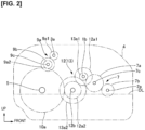
- Figure 2 is a schematic diagram in which gears in the first embodiment are viewed from an axial direction.
- the rotation shafts of the gears specifically the motor shaft 2a, the rotating shaft 7c, the input shaft 1b, the countershaft 12b, the motor shaft 3a, the rotating shaft 9c, and the driveshaft 5, are lined up in the stated order from the front side of the vehicle.
- the high-gear stage gear train 12 and the low-gear stage gear train 13 of the engine transmission mechanism 11 are disposed between the electric-power-generating-motor gear train 7 and the ring gear 10a in the vehicle longitudinal direction.
- the travel-motor gear train 9a is disposed above the ring gear 10a respect to the vertical direction.
- the lowermost ends of the driven gear 7b respect to the vertical direction, the ring gear 10a, the driven gear 12a2, and the driven gear 13a2 are positioned lower than an oil surface OL of lubricating oil that is retained in a lower section of the gear box 4 with respect to the vertical direction.
- the oil surface OL is set at a height at which the lower sections of the driven gear 7b with respect to the vertical direction, the ring gear 10a, the driven gear 12a2, and the driven gear 13a2 are continuously submerged.
- the drive gear 7a, the drive gear 9a1, the driven gear 9a2, the travel-motor final reduction gear 9b, the drive gear 12a1, and the drive gear 13a1 are lubricated by lubricating oil that has been thrust upward in the vertical direction due to rotation of the driven gear 7b, the ring gear 10a, the driven gear 12a2, and the driven gear 13a2.
- Figure 3 is a schematic diagram in which the engine transmission mechanism 11 in the first embodiment is viewed from an axis-orthogonal direction
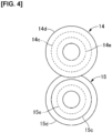
- Fig. 4 is a schematic diagram in which the high-gear stage clutch sleeve 14b and the low-gear stage clutch sleeve 15b in the first embodiment are viewed from an axial direction.
- the high-gear stage clutch sleeve 14b has two flange parts 14c, 14d and a shift fork groove 14e.
- the two flange parts 14c, 14d are provided at two axial-direction ends.
- the large-diameter flange part (first flange part) 14d that is located on a side closer to the drive gear 13a1, in the axial direction, is set so as to have a greater diameter than the small-diameter flange part 14c that is located on a side closer to the drive gear 12a1.
- the shift fork groove 14e is positioned between the two flange parts 14c, 14d in the axial direction.
- the shift fork groove 14e is set so as to have a smaller diameter than the small-diameter flange part 14c.
- Thrust is applied to the high-gear stage clutch sleeve 14b by a high-gear stage shift actuator (first actuator) 16, and the high-gear stage clutch sleeve 14b moves in the axial direction through a region from the right-side release position shown in Fig. 3 to the left-side engagement position at which the small-diameter flange part 14c comes into contact with the drive gear 12a1.
- the high-gear stage shift actuator 16 has a shift rod 16a and a shift fork 16b.
- the shift rod 16a is a rod-form body extending in the axial direction and moves in the axial direction in accordance with a command from a controller (not shown).
- the shift fork 16b protrudes in a forked shape from the shift rod 16a and fits into the shift fork groove 14e in the high-gear stage clutch sleeve 14b.
- a standby spring (first deflection spring) 18 is interposed between the shift fork 16b and the small-diameter flange part 14c in the axial direction.
- the standby spring 18 is disposed so as to be capable of propagating thrust applied from the shift fork 16b to the small-diameter flange part 14c.
- the standby spring 18 flexurally deforms in response to application of the thrust from the shift fork 16b. Pressing force is thereby applied to the high-gear stage clutch sleeve 14b, and interlocking-direction movement of the high-gear stage clutch sleeve 14b is deferred.
- the standby spring 18 is a standby mechanism in which a spring component is used, where the standby mechanism: accumulates thrust applied from the shift fork 16b and holds off interlocking-direction movement of the high-gear stage clutch sleeve 14b until a phase of the spline teeth of the high-gear stage clutch sleeve 14b matches a phase of the dog teeth of the dog gear 12a3; and, when the phase of the spline teeth of the high-gear stage clutch sleeve 14b and that of the dog teeth of the dog gear 12a3 have matched, causes the high-gear stage clutch sleeve 14b to move in the interlocking direction.
- the low-gear stage clutch sleeve 15b has two flange parts 15c, 15d and a shift fork groove 15e.
- the two flange parts 15c, 15d are provided at two axial-direction ends.
- the large-diameter flange part (second flange part) 15d that is located on a side closer to the driven gear 12a2, in the axial direction, is set so as to have a greater diameter than the small-diameter flange part 15c that is located on a side closer to the driven gear 13a2.
- the shift fork groove 15e is positioned between the two flange parts 15c, 15d in the axial direction.
- the shift fork groove 15e is set so as to have a smaller diameter than the small-diameter flange part 15c. Thrust is applied to the low-gear stage clutch sleeve 15b by a low-gear stage shift actuator (second actuator) 17, and the position of the low-gear stage clutch sleeve 15b moves in the axial direction through a region from the left-side release position shown in Fig. 3 to the right-side engagement position at which the small-diameter flange part 15c comes into contact with the driven gear 13a2.
- the low-gear stage shift actuator 17 has a shift rod 17a and a shift fork 17b.
- the shift rod 17a is a rod-form body extending in the axial direction and moves in the axial direction in accordance with a command from a controller (not shown).
- the shift fork 17b protrudes in a forked shape from the shift rod 17a and fits into the shift fork groove 15e in the low-gear stage clutch sleeve 15b.
- a standby spring (second deflection spring) 19 is interposed between the shift fork 17b and the small-diameter flange part 15c in the axial direction.
- the standby spring 19 is disposed so as to be capable of propagating thrust applied from the shift fork 17b to the small-diameter flange part 15c.
- the function of the standby spring 19 is identical to that of the standby spring 18, and therefore a detailed description of this function is omitted.
- the large-diameter flange part 14d of the high-gear stage clutch sleeve 14b and the small-diameter flange part 15c of the low-gear stage clutch sleeve 15b do not overlap in the axial direction.
- the small-diameter flange part 14c of the high-gear stage clutch sleeve 14b and the large-diameter flange part 15d of the low-gear stage clutch sleeve 15b do not overlap in the axial direction.
- x is an axial-direction distance between the two large-diameter flange parts 14d, 15d (distance between two large-diameter flange parts) when the two clutch sleeves 14b, 15b are both at release positions
- A is an axial-direction distance from the large-diameter flange part 14d to the dog gear 12a3 and an axial-direction distance from the large-diameter flange part 15d to the dog gear 13a3
- B is an axial-direction length of the two dog gears 12a3, 13a3 (distance from distal end to root).
- the two large-diameter flange parts 14d, 15d come into contact with each other before the one clutch sleeve arrives at the engagement position, whereby movement of the one clutch sleeve toward the engagement position is restricted.
- the two large-diameter flange parts 14d, 15d function as an interference member that interferes so that the other of the two clutch sleeves 14b, 15b cannot move to the engagement position.
- Figure 5 is a time chart showing countershaft differential rotation, input-shaft differential rotation, and a distance between the two large-diameter flange parts when the engine transmission mechanism 11 is switched from a low-gear stage to a high-gear stage.
- the low-gear stage clutch 15 In an interval until a time t1, the low-gear stage clutch 15 is in an engaged state, as shown in Fig. 6 .
- the dog gear 13a3 rotates integrally with the low-gear stage clutch sleeve 15b, the countershaft differential rotation, which is the difference in rotation speed between the low-gear stage clutch sleeve 15b and the dog gear 13a3, is zero.
- the dog gear 12a3 is stopped. Therefore, a fixed difference in rotation speed (input-shaft differential rotation) arises between the high-gear stage clutch sleeve 14b and the dog gear 12a3.
- the low-gear stage clutch sleeve 15b is at the right-side engagement position and the high-gear stage clutch sleeve 14b is at the right-side release position, the distance between the two large-diameter flange parts is x - (A + B).
- the controller drives the low-gear stage shift actuator 17 and causes the low-gear stage clutch sleeve 15b to move from the right-side engagement position to the left-side release position.
- the spline teeth of the low-gear stage clutch sleeve 15b and the dog teeth of the dog gear 13a3 thereby come out of mesh, and the low-gear stage clutch 15 enters a released state. Because the two clutch sleeves 14b, 15b are both at the release position, the distance between the two large-diameter flange parts reaches x (refer to Fig. 3 ).
- the speed of the electric-power-generating motor 2 is controlled so that the input-shaft differential rotation is minimized, whereby rotation of the high-gear stage clutch sleeve 14b and that of the dog gear 12a3 is synchronized.
- the input-shaft differential rotation is gradually decreased and the countershaft differential rotation is gradually increased in an interval from time t1 to a time t2.
- the controller drives the high-gear stage shift actuator 16 and causes the high-gear stage clutch sleeve 14b to move from the release position to the engagement position.
- the spline teeth of the high-gear stage clutch sleeve 14b and the dog teeth of the dog gear 13a3 thereby come out of mesh, and the high-gear stage clutch 14 enters an engaged state.
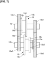
- the low-gear stage clutch sleeve 15b is at the left-side release position and the high-gear stage clutch sleeve 14b is at the left-side engagement position, as shown in Fig. 7 , the distance between the two large-diameter flange parts reaches x - (A + B).
- the engine transmission mechanism 11 in the first embodiment is provided with an interference member (large-diameter flange parts 14d, 15d) that interferes so that, when one of the low-gear stage clutch sleeve 15b and the high-gear stage clutch sleeve 14b is at an engagement position, the other cannot move to an engagement position.
- an interference member large-diameter flange parts 14d, 15d
- the large-diameter flange part 15d interferes with the large-diameter flange part 14d before the spline teeth of the high-gear stage clutch sleeve 14b and the dog teeth of the dog gear 13a3 mesh, and movement of the high-gear stage clutch sleeve 14b toward the left-side engagement position is restricted, even when thrust is applied to the high-gear stage clutch sleeve 14b due to erroneous actuation of the high-gear stage shift actuator 16.
- This makes it possible to avoid a circumstance where the high-gear stage clutch 14 enters an engaged state and to prevent the occurrence of unexpected interlocking. As a result, sudden changes in behavior of the vehicle caused by the occurrence of interlocking can be suppressed.
- the interference member includes the large-diameter flange part 14d provided to the high-gear stage clutch sleeve 14b and the large-diameter flange part 15d provided to the low-gear stage clutch sleeve 15b.
- the two large-diameter flange parts 14d, 15d have shapes that overlap as viewed from the axial direction. Specifically, providing the interference member to the two clutch sleeves 14b, 15b makes it possible to simplify the structure of the interference member and to reduce the number of components to a greater extent than in cases where interference member is provided separately.
- a + B ⁇ x ⁇ 2A + B is satisfied, where x is an axial-direction distance between the large-diameter flange part 14d and the large-diameter flange part 15d when the high-gear stage clutch sleeve 14b and the low-gear stage clutch sleeve 15b are both at release positions, A is an axial-direction distance from the high-gear stage clutch sleeve 14b to the dog gear 12a3 and an axial-direction distance from the low-gear stage clutch sleeve 15b to the dog gear 13a3, and B is an axial-direction length of the dog gear 12a3 and the dog gear 13a3.
- Setting x so as to be longer than A + B makes it possible for one clutch sleeve to reliably move to the engagement position from a state where the high-gear stage clutch sleeve 14b and the low-gear stage clutch sleeve 15b are both at the release positions. Specifically, the low-gear stage or the high-gear stage can be reliably selected.
- setting x so as to be shorter than 2A + B makes it possible, when one of the low-gear stage clutch sleeve 15b and the high-gear stage clutch sleeve 14b reaches the engagement position, for the amount by which the other clutch sleeve can move toward the engagement position to be less than A, and makes it possible to avoid interlocking of the other clutch sleeve and the dog gear. As a result, incidence of unexpected interlocking can be more reliably prevented.
- the engine transmission mechanism 11 is provided with: the high-gear stage shift actuator 16, which applies thrust to the high-gear stage clutch 14; the low-gear stage shift actuator 17, which applies thrust to the low-gear stage clutch 15; the standby spring 18, which is disposed so as to transmit thrust between the high-gear stage clutch sleeve 14b and the high-gear stage shift actuator 16 and which flexurally deforms in response to application of the thrust from the high-gear stage shift actuator 16; and the standby spring 19, which is disposed so as to transmit thrust between the low-gear stage clutch sleeve 15b and the low-gear stage shift actuator 17 and which flexurally deforms in response to application of the thrust from the low-gear stage shift actuator 17.
- the one clutch sleeve is reliably returned to the release position due to the interference of the two large-diameter flange parts 14d, 15d when the other clutch sleeve moves to the engagement position. This makes it possible to more reliably prevent incidence of unexpected interlocking.
- the interference member may be separate elements from the first clutch sleeve and the second clutch sleeve.
Landscapes
- Engineering & Computer Science (AREA)
- General Engineering & Computer Science (AREA)
- Mechanical Engineering (AREA)
- Mechanical Operated Clutches (AREA)
- Structure Of Transmissions (AREA)
- Control Of Transmission Device (AREA)
- Hybrid Electric Vehicles (AREA)
Description
- The present invention relates to a vehicle transmission.
-
Patent Document 1 discloses a series-scheme hybrid vehicle provided with an engine and an electric motor as sources of motive power for the vehicle. An output of the engine is transferred to a vehicle driveshaft via a two-stage transmission having a low-gear stage and a high-gear stage. -
Patent Document 2 discloses a transaxle device for a hybrid vehicle including an engine, a first rotating electric machine, and a second rotating electric machine individually transmits power of the engine and power of the first rotating electric machine to an output shaft on the side of a drive wheel from different power transmission paths and also transmits the power of the engine to the second rotating electric machine. The transaxle device in some embodiments ofPatent Document 2 comprises an idle gear rotatably supported on an input shaft and a fixed gear meshing with the idle gear and fixed on a first counter shaft. In addition, there is a further fixed gear fixed to the input shaft and a further idle gear rotatably supported by the first counter shaft. A sleeve is configured to move axially to the right from the idle state to engage a dog gear of the idle gear, and a further sleeve is configured to move axially to the left from the idle state to engage a further dog gear of the further idle gear.Patent Document 2 further discloses that a parking gear comprising a parking lock device is provided and, when a parking range is selected by the driver, the parking gear engages a parking sprag to prohibit rotation of a second counter shaft. -
Patent Document 3 discloses a device for preventing inadvertent selection of a parking lock function in a transmission. The transmission is configured to select a shift position (e.g. two gear ratios) and a parking lock function by means of a shift drum. A mechanical operating device (apparatus) is provided as a device for preventing incorrect selection. The apparatus prevents the selection of the parking lock position of the shift drum upon rotation of the shift drum in the first direction of rotation, then releases the prevention upon rotation of the shift drum in the second direction of rotation opposite the first direction of rotation, and then prevents the selection of the parking lock position in the first direction of rotation in the first rotational direction opposite to the second rotational direction. -
- Patent Document 1:
JP 2017-222197 A - Patent Document 2:
EP 3 453 548 A1 - Patent Document 3:
US 2017/0175890 A1 - However, in the prior art, a switch between two gear stages is performed by selectively engaging two dog clutches that are independent from each other. Therefore, there has been a concern that, when an actuator has erroneously actuated, unexpected interlocking will occur due to simultaneous engagement of the two dog clutches and vehicle behavior will suddenly change. It is an object of the present invention to provide a vehicle transmission in which it is possible to suppress incidence of unexpected interlocking.
- This object is solved by the vehicle transmission according to
claim 1. Further advantageous effects can be achieved by preferred embodiments defined in the appended dependent claims. The vehicle transmission according to the present invention comprises a first gear rotatably supported on a first shaft; a second gear secured to a second shaft and continuously meshed with the first gear; a first clutch sleeve that rotates integrally with the first shaft and that moves in an axial direction between a release position and an engagement position for interlocking with a first dog gear of the first gear; a third gear secured to the first shaft; a fourth gear rotatably supported on the second shaft and continuously meshed with the third gear; and a second clutch sleeve that rotates integrally with the second shaft and that moves in the axial direction between a release position and an engagement position for interlocking with a second dog gear of the fourth gear. The vehicle transmission is characterized by an interference member that interferes so that when one of the first clutch sleeve and the second clutch sleeve is at the engagement position, the other cannot move to the engagement position, wherein the interference member includes a first flange part provided to the first clutch sleeve and a second flange part provided to the second clutch sleeve, and wherein the first flange part and the second flange part have shapes that overlap as viewed from the axial direction. - This makes it possible to suppress incidence of unexpected interlocking in the present invention.
-
-
Figure 1 is a schematic diagram showing a drive system of a vehicle according to a first embodiment of the invention as claimed; -
Figure 2 is a schematic diagram in which gears in the first embodiment are viewed from an axial direction; -
Figure 3 is a schematic diagram in which anengine transmission mechanism 11 in the first embodiment is viewed from an axis-orthogonal direction; -
Figure 4 is a schematic diagram in which a high-gearstage clutch sleeve 14b and a low-gearstage clutch sleeve 15b in the first embodiment are viewed from an axial direction; -
Figure 5 is a time chart showing countershaft differential rotation, input-shaft differential rotation, and a distance between two large-diameter flange parts when theengine transmission mechanism 11 is switched from a low-gear stage to a high-gear stage; -
Figure 6 is a schematic diagram of the low-gear stage in theengine transmission mechanism 11; and -
Figure 7 is a schematic diagram of the high-gear stage in theengine transmission mechanism 11. -
- 1b Input shaft (first shaft)
- 12a1 Drive gear (first gear)
- 12a2 Driven gear (second gear)
- 12a3 Dog gear (first dog gear)
- 12b Countershaft (second shaft)
- 13a1 Drive gear (third gear)
- 13a2 Driven gear (fourth gear)
- 13a3 Dog gear (second dog gear)
- 14b High-gear stage clutch sleeve (first clutch sleeve)
- 14d Large-diameter flange part (interference member, first flange part)
- 15b Low-gear stage clutch sleeve (second clutch sleeve)
- 15d Large-diameter flange part (interference member, second flange part)
- 16 High-gear stage shift actuator (first actuator)
- 17 Low-gear stage shift actuator (second actuator)
- 18 Standby spring (first deflection spring)
- 19 Standby spring (second deflection spring)
-
Figure 1 is a schematic diagram showing a drive system of a vehicle according to a first embodiment. The vehicle in the first embodiment is a hybrid vehicle that can travel by switching between a series scheme and a parallel scheme. The vehicle is provided with anengine 1, an electric-power-generatingmotor 2, atravel motor 3, agear box 4, adriveshaft 5, anddrive wheels 6. In thegear box 4, a plurality of gear trains (electric-power-generating-motor gear train 7, a travel-motor reduction mechanism 9, adifferential 10, and an engine transmission mechanism 11) are accommodated inside a casing. Acrankshaft 1a of theengine 1 is provided integrally with an input shaft (first shaft) 1b accommodated in thegear box 4. Theinput shaft 1b is connected to amotor shaft 2a of the electric-power-generatingmotor 2 via the electric-power-generating-motor gear train 7. The electric-power-generating-motor gear train 7 has twogears drive gear 7a is secured to a rotatingshaft 7c and meshes with a drive gear (third gear) 13a1 that is secured to theinput shaft 1b. The drivengear 7b is secured to themotor shaft 2a. - A
motor shaft 3a of thetravel motor 3 can be coupled with a drive gear 9a1 of the travel-motor reduction mechanism 9 via a motor-travel clutch 8 accommodated in thegear box 4. The motor-travel clutch 8 is a dog clutch that is engaged by a meshing stroke in a rotation-synchronized state. The motor-travel clutch 8 has ahub 8a and a motorclutch sleeve 8b. Thehub 8a is secured to themotor shaft 3a. The motorclutch sleeve 8b is joined to thehub 8a so as to be incapable of rotating and so as to be capable of sliding in an axis direction of themotor shaft 3a (referred to as the axial direction below). Spline teeth (not shown) that are capable of meshing with dog teeth (not shown) of a dog gear 9a3 secured to the drive gear 9a1 are provided on a diameter-direction inner side of the motorclutch sleeve 8b. When the motorclutch sleeve 8b is at a left-side engagement position (left), the spline teeth of the motorclutch sleeve 8b and the dog teeth of the dog gear 9a3 mesh with each other, whereby themotor shaft 3a and the drive gear 9a1 of the travel-motor reduction mechanism 9 are coupled. However, when the motorclutch sleeve 8b is at a right-side release position (right), the spline teeth of the motorclutch sleeve 8b and the dog teeth of the dog gear 9a3 come out of mesh, whereby themotor shaft 3a and the drive gear 9a1 are uncoupled. - The travel-
motor reduction mechanism 9 has a travel-motor gear train 9a and a travel-motorfinal reduction gear 9b. The travel-motor gear train 9a has two gears 9a1, 9a2 that mesh with each other. The drive gear 9a1 is a free-rotating gear that is rotatably supported on themotor shaft 3a. The driven gear 9a2 is secured to arotating shaft 9c. The travel-motorfinal reduction gear 9b is secured to therotating shaft 9c. The travel-motorfinal reduction gear 9b meshes with aring gear 10a of the differential 10. In addition to thering gear 10a, the differential 10 is provided with adifferential case 10b having an actuating mechanism unit (not shown) in the interior thereof. Left/right side gears of the actuating mechanism unit are coupled with left/right driveshafts 5. The left/right driveshafts 5 are coupled with thedrive wheels 6. - The
engine transmission mechanism 11 is a vehicle transmission device configured to switch between a low-gear stage and a high-gear stage. Theengine transmission mechanism 11 has a high-gearstage gear train 12, a low-gearstage gear train 13, a high-gear stage clutch 14, and a low-gear stage clutch 15. The high-gearstage gear train 12 has two gears 12a1, 12a2 that mesh with each other. The drive gear (first gear) 12a1 is a free-rotating gear that is rotatably supported on theinput shaft 1b. The drive gear 12a1 can be coupled with theinput shaft 1b via the high-gear stage clutch 14. The driven gear (second gear) 12a2 is secured to a countershaft (second shaft) 12b and meshes with thering gear 10a of the differential 10. Specifically, the driven gear 12a2 additionally serves as a reduction small gear of a final reduction device (engine final reduction gear). The low-gearstage gear train 13 has two gears 13a1, 13a2 that mesh with each other. The driven gear (fourth gear) 13a2 is a free-rotating gear that is rotatably supported on thecountershaft 12b. The driven gear 13a2 can be coupled with thecountershaft 12b via the low-gear stage clutch 15. The low-gearstage gear train 13 has a higher reduction ratio than does the high-gearstage gear train 12. - The high-
gear stage clutch 14 is a dog clutch that is engaged by a meshing stroke in a rotation-synchronized state. The high-gear stage clutch 14 has ahub 14a and a high-gear stage clutch sleeve (first clutch sleeve) 14b. Thehub 14a is secured to theinput shaft 1b. The high-gear stageclutch sleeve 14b is joined to thehub 14a so as to be incapable of rotating and so as to be capable of sliding in the axial direction. Spline teeth (not shown) that are capable of meshing with dog teeth (not shown) of a dog gear (first dog gear) 12a3 secured to the drive gear 12a1 are provided on a diameter-direction inner side of the high-gear stageclutch sleeve 14b. When the high-gear stageclutch sleeve 14b of the high-gear stage clutch 14 is at a left-side engagement position (left), the spline teeth of the high-gear stageclutch sleeve 14b and the dog teeth of the dog gear 12a3 mesh with each other, whereby the drive gear 12a1 and theinput shaft 1b are coupled. However, when the high-gear stageclutch sleeve 14b is at a right-side release position (right), the spline teeth of the high-gear stageclutch sleeve 14b and the dog teeth of the dog gear 12a3 come out of mesh, whereby the drive gear 12a1 and theinput shaft 1b are uncoupled. - The low-
gear stage clutch 15 is a dog clutch that is engaged by a meshing stroke in a rotation-synchronized state. The low-gear stage clutch 15 has ahub 15a and a low-gear stage clutch sleeve (second clutch sleeve) 15b. Thehub 15a is secured to thecountershaft 12b. The low-gear stageclutch sleeve 15b is joined to thehub 15a so as to be incapable of rotating and so as to be capable of sliding in the axial direction. Spline teeth (not shown) that are capable of meshing with dog teeth (not shown) of a dog gear (second dog gear) 13a3 secured to the driven gear 13a2 are provided on a diameter-direction inner side of the low-gear stageclutch sleeve 15b. When the low-gear stageclutch sleeve 15b of the low-gear stage clutch 15 is at a right-side engagement position (right), the spline teeth of the low-gear stageclutch sleeve 15b and the dog teeth of the dog gear 13a3 mesh with each other, whereby the driven gear 13a2 and thecountershaft 12b are coupled. However, when the low-gear stageclutch sleeve 15b is at a left-side release position (left), the spline teeth of the low-gear stageclutch sleeve 15b and the dog teeth of the dog gear 13a3 come out of mesh, whereby the driven gear 13a2 and thecountershaft 12b are uncoupled. Three planes P1, P2, P3 that extend in a direction orthogonal to the axis direction of thecrankshaft 1a are established. The planes P1, P2, P3 are parallel to each other. The first plane P1 and the second plane P2 are positioned on the right and left sides, respectively, and the third plane P3 is positioned between the first plane P1 and the second plane P2. The electric-power-generating-motor gear train 7, the low-gearstage gear train 13, and the travel-motor reduction mechanism 9 are disposed on the first plane P1. The high-gearstage gear train 12 and the differential 10 are disposed on the second plane P2. (The sleeves of) the high-gear stage clutch 14, the low-gear stage clutch 15, and the motor-travel clutch 8 are disposed on the third plane P3. - In the vehicle in the first embodiment, engaging the motor-
travel clutch 8 and releasing both of the high-gear stage clutch 14 and the low-gear stage clutch 15 effects travel under a series hybrid mode in which only thetravel motor 3 is used as a motive power source for travel and theengine 1 is used as a motive power source for electric power generation. In addition, releasing the motor-travel clutch 8 and selectively engaging one of the high-gear stage clutch 14 and the low-gear stage clutch 15 effects travel under an engine direct coupling mode in which only theengine 1 is used as a motive power source for travel. Theengine transmission mechanism 11 either reaches a high-gear stage due to engagement of the high-gear stage clutch 14 or reaches a low-gear stage due to engagement of the low-gear stage clutch 15. In the vehicle in the first embodiment, engaging the motor-travel clutch 8 in a state where one of the high-gear stage clutch 14 and the low-gear stage clutch 15 has been engaged enables travel in a parallel hybrid mode. -
Figure 2 is a schematic diagram in which gears in the first embodiment are viewed from an axial direction. The rotation shafts of the gears, specifically themotor shaft 2a, therotating shaft 7c, theinput shaft 1b, thecountershaft 12b, themotor shaft 3a, therotating shaft 9c, and thedriveshaft 5, are lined up in the stated order from the front side of the vehicle. The high-gearstage gear train 12 and the low-gearstage gear train 13 of theengine transmission mechanism 11 are disposed between the electric-power-generating-motor gear train 7 and thering gear 10a in the vehicle longitudinal direction. The travel-motor gear train 9a is disposed above thering gear 10a respect to the vertical direction. The lowermost ends of the drivengear 7b respect to the vertical direction, thering gear 10a, the driven gear 12a2, and the driven gear 13a2 are positioned lower than an oil surface OL of lubricating oil that is retained in a lower section of thegear box 4 with respect to the vertical direction. The oil surface OL is set at a height at which the lower sections of the drivengear 7b with respect to the vertical direction, thering gear 10a, the driven gear 12a2, and the driven gear 13a2 are continuously submerged. Thedrive gear 7a, the drive gear 9a1, the driven gear 9a2, the travel-motorfinal reduction gear 9b, the drive gear 12a1, and the drive gear 13a1 are lubricated by lubricating oil that has been thrust upward in the vertical direction due to rotation of the drivengear 7b, thering gear 10a, the driven gear 12a2, and the driven gear 13a2. -
Figure 3 is a schematic diagram in which theengine transmission mechanism 11 in the first embodiment is viewed from an axis-orthogonal direction, andFig. 4 is a schematic diagram in which the high-gear stageclutch sleeve 14b and the low-gear stageclutch sleeve 15b in the first embodiment are viewed from an axial direction. The high-gear stageclutch sleeve 14b has twoflange parts shift fork groove 14e. The twoflange parts diameter flange part 14c that is located on a side closer to the drive gear 12a1. Theshift fork groove 14e is positioned between the twoflange parts shift fork groove 14e is set so as to have a smaller diameter than the small-diameter flange part 14c. Thrust is applied to the high-gear stageclutch sleeve 14b by a high-gear stage shift actuator (first actuator) 16, and the high-gear stageclutch sleeve 14b moves in the axial direction through a region from the right-side release position shown inFig. 3 to the left-side engagement position at which the small-diameter flange part 14c comes into contact with the drive gear 12a1. The high-gearstage shift actuator 16 has ashift rod 16a and ashift fork 16b. Theshift rod 16a is a rod-form body extending in the axial direction and moves in the axial direction in accordance with a command from a controller (not shown). Theshift fork 16b protrudes in a forked shape from theshift rod 16a and fits into theshift fork groove 14e in the high-gear stageclutch sleeve 14b. - A standby spring (first deflection spring) 18 is interposed between the
shift fork 16b and the small-diameter flange part 14c in the axial direction. Thestandby spring 18 is disposed so as to be capable of propagating thrust applied from theshift fork 16b to the small-diameter flange part 14c. When theshift fork 16b moves toward an interlocking direction (direction approaching the drive gear 12a1), thestandby spring 18 flexurally deforms in response to application of the thrust from theshift fork 16b. Pressing force is thereby applied to the high-gear stageclutch sleeve 14b, and interlocking-direction movement of the high-gear stageclutch sleeve 14b is deferred. Specifically, thestandby spring 18 is a standby mechanism in which a spring component is used, where the standby mechanism: accumulates thrust applied from theshift fork 16b and holds off interlocking-direction movement of the high-gear stageclutch sleeve 14b until a phase of the spline teeth of the high-gear stageclutch sleeve 14b matches a phase of the dog teeth of the dog gear 12a3; and, when the phase of the spline teeth of the high-gear stageclutch sleeve 14b and that of the dog teeth of the dog gear 12a3 have matched, causes the high-gear stageclutch sleeve 14b to move in the interlocking direction. - The low-gear stage
clutch sleeve 15b has twoflange parts shift fork groove 15e. The twoflange parts diameter flange part 15c that is located on a side closer to the driven gear 13a2. Theshift fork groove 15e is positioned between the twoflange parts shift fork groove 15e is set so as to have a smaller diameter than the small-diameter flange part 15c. Thrust is applied to the low-gear stageclutch sleeve 15b by a low-gear stage shift actuator (second actuator) 17, and the position of the low-gear stageclutch sleeve 15b moves in the axial direction through a region from the left-side release position shown inFig. 3 to the right-side engagement position at which the small-diameter flange part 15c comes into contact with the driven gear 13a2. The low-gearstage shift actuator 17 has ashift rod 17a and ashift fork 17b. Theshift rod 17a is a rod-form body extending in the axial direction and moves in the axial direction in accordance with a command from a controller (not shown). Theshift fork 17b protrudes in a forked shape from theshift rod 17a and fits into theshift fork groove 15e in the low-gear stageclutch sleeve 15b. A standby spring (second deflection spring) 19 is interposed between theshift fork 17b and the small-diameter flange part 15c in the axial direction. Thestandby spring 19 is disposed so as to be capable of propagating thrust applied from theshift fork 17b to the small-diameter flange part 15c. The function of thestandby spring 19 is identical to that of thestandby spring 18, and therefore a detailed description of this function is omitted. - Outer-peripheral-side portions of the large-
diameter flange part 14d of the high-gear stageclutch sleeve 14b and the large-diameter flange part 15d of the low-gear stageclutch sleeve 15b overlap as viewed from the axial direction, as shown inFig. 4 . However, the large-diameter flange part 14d of the high-gear stageclutch sleeve 14b and the small-diameter flange part 15c of the low-gear stageclutch sleeve 15b do not overlap in the axial direction. Similarly, the small-diameter flange part 14c of the high-gear stageclutch sleeve 14b and the large-diameter flange part 15d of the low-gear stageclutch sleeve 15b do not overlap in the axial direction. In addition, the following expression (1) is satisfied, where x is an axial-direction distance between the two large-diameter flange parts clutch sleeves diameter flange part 14d to the dog gear 12a3 and an axial-direction distance from the large-diameter flange part 15d to the dog gear 13a3, and B is an axial-direction length of the two dog gears 12a3, 13a3 (distance from distal end to root).
- Thus, in cases where one of the two
clutch sleeves clutch sleeves diameter flange parts clutch sleeves diameter flange parts clutch sleeves - Effects of the first embodiment are described next.
Figure 5 is a time chart showing countershaft differential rotation, input-shaft differential rotation, and a distance between the two large-diameter flange parts when theengine transmission mechanism 11 is switched from a low-gear stage to a high-gear stage. In an interval until a time t1, the low-gear stage clutch 15 is in an engaged state, as shown inFig. 6 . At this time, because the dog gear 13a3 rotates integrally with the low-gear stageclutch sleeve 15b, the countershaft differential rotation, which is the difference in rotation speed between the low-gear stageclutch sleeve 15b and the dog gear 13a3, is zero. Because the high-gear stage clutch 14 is in a released state, the dog gear 12a3 is stopped. Therefore, a fixed difference in rotation speed (input-shaft differential rotation) arises between the high-gear stageclutch sleeve 14b and the dog gear 12a3. In addition, because the low-gear stageclutch sleeve 15b is at the right-side engagement position and the high-gear stageclutch sleeve 14b is at the right-side release position, the distance between the two large-diameter flange parts is x - (A + B). - At time t1, because the high-gear stage is selected due to a driver or a travel state (e.g., speed), the controller drives the low-gear
stage shift actuator 17 and causes the low-gear stageclutch sleeve 15b to move from the right-side engagement position to the left-side release position. The spline teeth of the low-gear stageclutch sleeve 15b and the dog teeth of the dog gear 13a3 thereby come out of mesh, and the low-gear stage clutch 15 enters a released state. Because the twoclutch sleeves Fig. 3 ). In addition, the speed of the electric-power-generatingmotor 2 is controlled so that the input-shaft differential rotation is minimized, whereby rotation of the high-gear stageclutch sleeve 14b and that of the dog gear 12a3 is synchronized. Thus, the input-shaft differential rotation is gradually decreased and the countershaft differential rotation is gradually increased in an interval from time t1 to a time t2. - At time t2, because the input-shaft differential rotation has been minimized, the controller drives the high-gear
stage shift actuator 16 and causes the high-gear stageclutch sleeve 14b to move from the release position to the engagement position. The spline teeth of the high-gear stageclutch sleeve 14b and the dog teeth of the dog gear 13a3 thereby come out of mesh, and the high-gear stage clutch 14 enters an engaged state. At this time, because the low-gear stageclutch sleeve 15b is at the left-side release position and the high-gear stageclutch sleeve 14b is at the left-side engagement position, as shown inFig. 7 , the distance between the two large-diameter flange parts reaches x - (A + B). - As described above, the
engine transmission mechanism 11 in the first embodiment is provided with an interference member (large-diameter flange parts clutch sleeve 15b and the high-gear stageclutch sleeve 14b is at an engagement position, the other cannot move to an engagement position. Therefore, when, for example, the low-gear stage clutch 15 is in an engaged state, the large-diameter flange part 15d interferes with the large-diameter flange part 14d before the spline teeth of the high-gear stageclutch sleeve 14b and the dog teeth of the dog gear 13a3 mesh, and movement of the high-gear stageclutch sleeve 14b toward the left-side engagement position is restricted, even when thrust is applied to the high-gear stageclutch sleeve 14b due to erroneous actuation of the high-gearstage shift actuator 16. This makes it possible to avoid a circumstance where the high-gear stage clutch 14 enters an engaged state and to prevent the occurrence of unexpected interlocking. As a result, sudden changes in behavior of the vehicle caused by the occurrence of interlocking can be suppressed. - The interference member includes the large-
diameter flange part 14d provided to the high-gear stageclutch sleeve 14b and the large-diameter flange part 15d provided to the low-gear stageclutch sleeve 15b. The two large-diameter flange parts clutch sleeves - The expression A + B < x < 2A + B is satisfied, where x is an axial-direction distance between the large-
diameter flange part 14d and the large-diameter flange part 15d when the high-gear stageclutch sleeve 14b and the low-gear stageclutch sleeve 15b are both at release positions, A is an axial-direction distance from the high-gear stageclutch sleeve 14b to the dog gear 12a3 and an axial-direction distance from the low-gear stageclutch sleeve 15b to the dog gear 13a3, and B is an axial-direction length of the dog gear 12a3 and the dog gear 13a3. Setting x so as to be longer than A + B makes it possible for one clutch sleeve to reliably move to the engagement position from a state where the high-gear stageclutch sleeve 14b and the low-gear stageclutch sleeve 15b are both at the release positions. Specifically, the low-gear stage or the high-gear stage can be reliably selected. In addition, setting x so as to be shorter than 2A + B makes it possible, when one of the low-gear stageclutch sleeve 15b and the high-gear stageclutch sleeve 14b reaches the engagement position, for the amount by which the other clutch sleeve can move toward the engagement position to be less than A, and makes it possible to avoid interlocking of the other clutch sleeve and the dog gear. As a result, incidence of unexpected interlocking can be more reliably prevented. - The
engine transmission mechanism 11 is provided with: the high-gearstage shift actuator 16, which applies thrust to the high-gear stage clutch 14; the low-gearstage shift actuator 17, which applies thrust to the low-gear stage clutch 15; thestandby spring 18, which is disposed so as to transmit thrust between the high-gear stageclutch sleeve 14b and the high-gearstage shift actuator 16 and which flexurally deforms in response to application of the thrust from the high-gearstage shift actuator 16; and thestandby spring 19, which is disposed so as to transmit thrust between the low-gear stageclutch sleeve 15b and the low-gearstage shift actuator 17 and which flexurally deforms in response to application of the thrust from the low-gearstage shift actuator 17. In a transmission mechanism in which selectively engaging two dog clutches that are independent from each other enables switching between two gear stages, during switching between gear stages in cases where dog clutches having standby springs are employed, there are situations where an interlocking state of dog gears is maintained by extension or retraction of the standby springs even when, in a release-side dog clutch, a shift actuator is moved from a position that corresponds to an engagement position of a clutch sleeve to a position that corresponds to a release position thereof, and interlocking readily occurs. However, in theengine transmission mechanism 11 in the first embodiment, even in cases where a state of interlocking with the dog gear 12a3 or the dog gear 13a3 is maintained for one of the high-gear stageclutch sleeve 14b and the low-gear stageclutch sleeve 15b due to extension of thestandby spring 18 or thestandby spring 19, the one clutch sleeve is reliably returned to the release position due to the interference of the two large-diameter flange parts - A mode for carrying out the present invention has been described above on the basis of the embodiment, but the specific configuration of the present invention is not limited to this embodiment; design changes, etc., that do not depart from the invention being defined in the claims are also included in the present invention. For example, the interference member may be separate elements from the first clutch sleeve and the second clutch sleeve.
Claims (3)
- A vehicle transmission comprising:a first gear (12a1) rotatably supported on a first shaft (1b);a second gear (12a2) secured to a second shaft (12b) and continuously meshed with the first gear (12a1);a first clutch sleeve (14b) that rotates integrally with the first shaft (1b) and that moves in an axial direction between a release position and an engagement position for interlocking with a first dog gear (12a3) of the first gear (12a1);a third gear (13a1) secured to the first shaft (1b);a fourth gear (13a2) rotatably supported on the second shaft (12b) and continuously meshed with the third gear (13a1); anda second clutch sleeve (15b) that rotates integrally with the second shaft (12b) and that moves in the axial direction between a release position and an engagement position for interlocking with a second dog gear (13a3) of the fourth gear (13a2);characterized by:an interference member (14d, 15d) that interferes so that when one of the first clutch sleeve (14b) and the second clutch sleeve (15b) is at the engagement position, the other cannot move to the engagement position;wherein the interference member (14d, 15d) includes a first flange part (14d) provided to the first clutch sleeve (14b) and a second flange part (15d) provided to the second clutch sleeve (15b), andwherein the first flange part (14d) and the second flange part (15d) have shapes that overlap as viewed from the axial direction.
- The vehicle transmission according to claim 1, wherein
the following expression is satisfied, x is an axial-direction distance between the first flange part (14d) and the second flange part (15d) when the first clutch sleeve (14b) and the second clutch sleeve (15b) are both at the release positions,A is an axial-direction distance from the first clutch sleeve (14b) to the first dog gear (12a3) and an axial-direction distance from the second clutch (15b) sleeve to the second dog gear (13a3), andB is an axial-direction length of the first dog gear (12a3) and the second dog gear (13a3).
 - The vehicle transmission according to any of claims 1 or 2, further comprising:a first actuator (16) configured to apply thrust to the first clutch sleeve (14b);a second actuator (17) configured to apply thrust to the second clutch sleeve (15b);a first deflection spring (18) disposed to transmit thrust between the first clutch sleeve (14b) and the first actuator (16), the first deflection spring (18) flexing and deforming in response to application of the thrust from the first actuator (16); anda second deflection spring (19) disposed so as to transmit thrust between the second clutch sleeve (15b) and the second actuator (17), the second deflection spring (19) flexing and deforming in response to application of the thrust from the second actuator (17).
Applications Claiming Priority (1)
| Application Number | Priority Date | Filing Date | Title |
|---|---|---|---|
| PCT/IB2019/000643 WO2020260915A1 (en) | 2019-06-26 | 2019-06-26 | Vehicle transmission |
Publications (3)
| Publication Number | Publication Date |
|---|---|
| EP3992495A1 EP3992495A1 (en) | 2022-05-04 |
| EP3992495A4 EP3992495A4 (en) | 2022-06-22 |
| EP3992495B1 true EP3992495B1 (en) | 2025-02-26 |
Family
ID=74060517
Family Applications (1)
| Application Number | Title | Priority Date | Filing Date |
|---|---|---|---|
| EP19935497.8A Active EP3992495B1 (en) | 2019-06-26 | 2019-06-26 | Vehicle transmission |
Country Status (5)
| Country | Link |
|---|---|
| US (1) | US11619300B2 (en) |
| EP (1) | EP3992495B1 (en) |
| JP (1) | JP7160200B2 (en) |
| CN (1) | CN114008350B (en) |
| WO (1) | WO2020260915A1 (en) |
Families Citing this family (2)
| Publication number | Priority date | Publication date | Assignee | Title |
|---|---|---|---|---|
| CN115823193A (en) * | 2022-11-01 | 2023-03-21 | 南京高精齿轮集团有限公司 | Gear shifting gear box, gear shifting method and chemical equipment |
| US12228207B1 (en) * | 2024-05-14 | 2025-02-18 | Dmitri Millard | Transmission brake system and trans brake mechanism |
Family Cites Families (14)
| Publication number | Priority date | Publication date | Assignee | Title |
|---|---|---|---|---|
| JPS57138484A (en) * | 1981-02-18 | 1982-08-26 | Honda Motor Co Ltd | Variable speed gear for autobicycle |
| JPS6119164U (en) * | 1984-07-09 | 1986-02-04 | 富士重工業株式会社 | Shift operation mechanism of horizontal transmission |
| CN101386265B (en) * | 2000-10-20 | 2012-02-01 | 卢克摩擦片和离合器两合公司 | Gearbox for motor vehicle |
| JP4259521B2 (en) * | 2005-12-28 | 2009-04-30 | トヨタ自動車株式会社 | Automatic transmission for vehicles |
| JP4810472B2 (en) * | 2007-03-12 | 2011-11-09 | 愛知機械工業株式会社 | Twin clutch transmission |
| JP5734039B2 (en) * | 2011-03-22 | 2015-06-10 | 本田技研工業株式会社 | Saddle-type vehicle transmission |
| GB2506199A (en) * | 2012-09-25 | 2014-03-26 | Qinetiq Ltd | Drive member selection mechanism having torque transmitting projections on each face |
| JP6152669B2 (en) * | 2013-03-14 | 2017-06-28 | 株式会社ジェイテクト | Electromagnetic clutch device, four-wheel drive vehicle, electromagnetic clutch control method, and four-wheel drive vehicle control method |
| CN105874245B (en) * | 2013-12-26 | 2018-04-13 | 爱信艾达株式会社 | The hydraulic pressure control device of automatic transmission |
| CN106051070B (en) * | 2015-04-08 | 2018-05-29 | 本田技研工业株式会社 | Speed change gear |
| JP2017008959A (en) * | 2015-06-17 | 2017-01-12 | 本田技研工業株式会社 | Transmission gearbox |
| DE102015122085B4 (en) * | 2015-12-17 | 2025-06-18 | Dr. Ing. H.C. F. Porsche Aktiengesellschaft | Device for preventing unintentional activation of a parking lock function in a transmission |
| US10807457B2 (en) * | 2016-06-13 | 2020-10-20 | Mitsubishi Jidosha Kogyo Kabushiki Kaisha | Transaxle device for hybrid vehicle having connection/disconnection mechanism that enables or disables transmission of power of electric machine |
| JP6819083B2 (en) | 2016-06-13 | 2021-01-27 | 三菱自動車工業株式会社 | Transaxle device |
-
2019
- 2019-06-26 US US17/615,601 patent/US11619300B2/en active Active
- 2019-06-26 CN CN201980097562.3A patent/CN114008350B/en active Active
- 2019-06-26 WO PCT/IB2019/000643 patent/WO2020260915A1/en not_active Ceased
- 2019-06-26 EP EP19935497.8A patent/EP3992495B1/en active Active
- 2019-06-26 JP JP2021528013A patent/JP7160200B2/en active Active
Also Published As
| Publication number | Publication date |
|---|---|
| EP3992495A4 (en) | 2022-06-22 |
| JP7160200B2 (en) | 2022-10-25 |
| US11619300B2 (en) | 2023-04-04 |
| WO2020260915A1 (en) | 2020-12-30 |
| CN114008350B (en) | 2024-06-11 |
| JPWO2020260915A1 (en) | 2021-12-16 |
| US20220196146A1 (en) | 2022-06-23 |
| CN114008350A (en) | 2022-02-01 |
| EP3992495A1 (en) | 2022-05-04 |
Similar Documents
| Publication | Publication Date | Title |
|---|---|---|
| JP4836664B2 (en) | Vehicle driving force transmission device | |
| US8746099B2 (en) | Control system of transmission | |
| CN101275624B (en) | Transmission for vehicles | |
| EP2530356B1 (en) | Vehicle drive system | |
| US20070209461A1 (en) | Actuator mechanism for shift motors of a transmission | |
| EP2951044B1 (en) | Gear shift mechanism | |
| US4356879A (en) | Manipulation device for a transmission apparatus | |
| US4170273A (en) | Transmission apparatus for four-wheel drive motor vehicle | |
| US20140245861A1 (en) | Manual transmission | |
| CN112867620A (en) | Transmission and drive system for a motor vehicle | |
| CN104254456B (en) | Transfer case sprocket wheel idler gear activates | |
| JP7753436B2 (en) | Disconnector Device | |
| US20240336131A1 (en) | Clutch assembly for a differential of a motor vehicle | |
| EP3992495B1 (en) | Vehicle transmission | |
| CN115030995A (en) | Module for a system for synchronizing and driving the countershafts of a gearbox of a transmission | |
| JP2011510236A (en) | A gear switching control device for a vehicle transmission provided with a rotating drum having a main cam and an auxiliary cam. | |
| CN113494583A (en) | Differential mechanism and automobile transmission system with same | |
| CN110914578A (en) | Switching control device in gearbox | |
| US20200094674A1 (en) | Four-wheel drive vehicle | |
| US10436319B2 (en) | Method for controlling a gearbox, a gearbox and a vehicle provided with such a gearbox | |
| EP3812616A1 (en) | Electric vehicle driving apparatus | |
| JP4513450B2 (en) | Actuator | |
| JP3513135B2 (en) | Transmission for vehicles | |
| EP4707643A1 (en) | Motor vehicle with an engagement device of a gearbox and a parking break driven by a same actuator | |
| JPS645158Y2 (en) |
Legal Events
| Date | Code | Title | Description |
|---|---|---|---|
| STAA | Information on the status of an ep patent application or granted ep patent |
Free format text: STATUS: THE INTERNATIONAL PUBLICATION HAS BEEN MADE |
|
| PUAI | Public reference made under article 153(3) epc to a published international application that has entered the european phase |
Free format text: ORIGINAL CODE: 0009012 |
|
| STAA | Information on the status of an ep patent application or granted ep patent |
Free format text: STATUS: REQUEST FOR EXAMINATION WAS MADE |
|
| 17P | Request for examination filed |
Effective date: 20220113 |
|
| AK | Designated contracting states |
Kind code of ref document: A1 Designated state(s): AL AT BE BG CH CY CZ DE DK EE ES FI FR GB GR HR HU IE IS IT LI LT LU LV MC MK MT NL NO PL PT RO RS SE SI SK SM TR |
|
| REG | Reference to a national code |
Ref country code: DE Free format text: PREVIOUS MAIN CLASS: F16H0003660000 Ipc: F16D0011040000 Ref country code: DE Ref legal event code: R079 Ref document number: 602019066694 Country of ref document: DE Free format text: PREVIOUS MAIN CLASS: F16H0003660000 Ipc: F16D0011040000 |
|
| A4 | Supplementary search report drawn up and despatched |
Effective date: 20220524 |
|
| RIC1 | Information provided on ipc code assigned before grant |
Ipc: F16H 61/04 20060101ALN20220518BHEP Ipc: F16H 63/30 20060101ALI20220518BHEP Ipc: F16H 61/18 20060101ALI20220518BHEP Ipc: F16H 3/089 20060101ALI20220518BHEP Ipc: F16D 11/04 20060101AFI20220518BHEP |
|
| DAV | Request for validation of the european patent (deleted) | ||
| DAX | Request for extension of the european patent (deleted) | ||
| STAA | Information on the status of an ep patent application or granted ep patent |
Free format text: STATUS: EXAMINATION IS IN PROGRESS |
|
| 17Q | First examination report despatched |
Effective date: 20240313 |
|
| RIC1 | Information provided on ipc code assigned before grant |
Ipc: F16H 61/04 20060101ALN20241011BHEP Ipc: F16H 63/30 20060101ALI20241011BHEP Ipc: F16H 61/18 20060101ALI20241011BHEP Ipc: F16H 3/089 20060101ALI20241011BHEP Ipc: F16D 11/04 20060101AFI20241011BHEP |
|
| GRAP | Despatch of communication of intention to grant a patent |
Free format text: ORIGINAL CODE: EPIDOSNIGR1 |
|
| STAA | Information on the status of an ep patent application or granted ep patent |
Free format text: STATUS: GRANT OF PATENT IS INTENDED |
|
| RIC1 | Information provided on ipc code assigned before grant |
Ipc: F16H 61/04 20060101ALN20241111BHEP Ipc: F16H 63/30 20060101ALI20241111BHEP Ipc: F16H 61/18 20060101ALI20241111BHEP Ipc: F16H 3/089 20060101ALI20241111BHEP Ipc: F16D 11/04 20060101AFI20241111BHEP |
|
| INTG | Intention to grant announced |
Effective date: 20241204 |
|
| GRAS | Grant fee paid |
Free format text: ORIGINAL CODE: EPIDOSNIGR3 |
|
| GRAA | (expected) grant |
Free format text: ORIGINAL CODE: 0009210 |
|
| STAA | Information on the status of an ep patent application or granted ep patent |
Free format text: STATUS: THE PATENT HAS BEEN GRANTED |
|
| AK | Designated contracting states |
Kind code of ref document: B1 Designated state(s): AL AT BE BG CH CY CZ DE DK EE ES FI FR GB GR HR HU IE IS IT LI LT LU LV MC MK MT NL NO PL PT RO RS SE SI SK SM TR |
|
| REG | Reference to a national code |
Ref country code: GB Ref legal event code: FG4D |
|
| REG | Reference to a national code |
Ref country code: CH Ref legal event code: EP |
|
| REG | Reference to a national code |
Ref country code: DE Ref legal event code: R096 Ref document number: 602019066694 Country of ref document: DE |
|
| REG | Reference to a national code |
Ref country code: IE Ref legal event code: FG4D |
|
| REG | Reference to a national code |
Ref country code: NL Ref legal event code: MP Effective date: 20250226 |
|
| PG25 | Lapsed in a contracting state [announced via postgrant information from national office to epo] |
Ref country code: RS Free format text: LAPSE BECAUSE OF FAILURE TO SUBMIT A TRANSLATION OF THE DESCRIPTION OR TO PAY THE FEE WITHIN THE PRESCRIBED TIME-LIMIT Effective date: 20250526 |
|
| PG25 | Lapsed in a contracting state [announced via postgrant information from national office to epo] |
Ref country code: FI Free format text: LAPSE BECAUSE OF FAILURE TO SUBMIT A TRANSLATION OF THE DESCRIPTION OR TO PAY THE FEE WITHIN THE PRESCRIBED TIME-LIMIT Effective date: 20250226 |
|
| PG25 | Lapsed in a contracting state [announced via postgrant information from national office to epo] |
Ref country code: PL Free format text: LAPSE BECAUSE OF FAILURE TO SUBMIT A TRANSLATION OF THE DESCRIPTION OR TO PAY THE FEE WITHIN THE PRESCRIBED TIME-LIMIT Effective date: 20250226 |
|
| PGFP | Annual fee paid to national office [announced via postgrant information from national office to epo] |
Ref country code: DE Payment date: 20250520 Year of fee payment: 7 |
|
| PG25 | Lapsed in a contracting state [announced via postgrant information from national office to epo] |
Ref country code: ES Free format text: LAPSE BECAUSE OF FAILURE TO SUBMIT A TRANSLATION OF THE DESCRIPTION OR TO PAY THE FEE WITHIN THE PRESCRIBED TIME-LIMIT Effective date: 20250226 |
|
| PGFP | Annual fee paid to national office [announced via postgrant information from national office to epo] |
Ref country code: GB Payment date: 20250520 Year of fee payment: 7 |
|
| REG | Reference to a national code |
Ref country code: LT Ref legal event code: MG9D |
|
| PG25 | Lapsed in a contracting state [announced via postgrant information from national office to epo] |
Ref country code: NO Free format text: LAPSE BECAUSE OF FAILURE TO SUBMIT A TRANSLATION OF THE DESCRIPTION OR TO PAY THE FEE WITHIN THE PRESCRIBED TIME-LIMIT Effective date: 20250526 Ref country code: IS Free format text: LAPSE BECAUSE OF FAILURE TO SUBMIT A TRANSLATION OF THE DESCRIPTION OR TO PAY THE FEE WITHIN THE PRESCRIBED TIME-LIMIT Effective date: 20250626 |
|
| PG25 | Lapsed in a contracting state [announced via postgrant information from national office to epo] |
Ref country code: NL Free format text: LAPSE BECAUSE OF FAILURE TO SUBMIT A TRANSLATION OF THE DESCRIPTION OR TO PAY THE FEE WITHIN THE PRESCRIBED TIME-LIMIT Effective date: 20250226 |
|
| PG25 | Lapsed in a contracting state [announced via postgrant information from national office to epo] |
Ref country code: HR Free format text: LAPSE BECAUSE OF FAILURE TO SUBMIT A TRANSLATION OF THE DESCRIPTION OR TO PAY THE FEE WITHIN THE PRESCRIBED TIME-LIMIT Effective date: 20250226 |
|
| PG25 | Lapsed in a contracting state [announced via postgrant information from national office to epo] |
Ref country code: LV Free format text: LAPSE BECAUSE OF FAILURE TO SUBMIT A TRANSLATION OF THE DESCRIPTION OR TO PAY THE FEE WITHIN THE PRESCRIBED TIME-LIMIT Effective date: 20250226 Ref country code: PT Free format text: LAPSE BECAUSE OF FAILURE TO SUBMIT A TRANSLATION OF THE DESCRIPTION OR TO PAY THE FEE WITHIN THE PRESCRIBED TIME-LIMIT Effective date: 20250626 |
|
| PGFP | Annual fee paid to national office [announced via postgrant information from national office to epo] |
Ref country code: FR Payment date: 20250520 Year of fee payment: 7 |
|
| PG25 | Lapsed in a contracting state [announced via postgrant information from national office to epo] |
Ref country code: GR Free format text: LAPSE BECAUSE OF FAILURE TO SUBMIT A TRANSLATION OF THE DESCRIPTION OR TO PAY THE FEE WITHIN THE PRESCRIBED TIME-LIMIT Effective date: 20250527 Ref country code: BG Free format text: LAPSE BECAUSE OF FAILURE TO SUBMIT A TRANSLATION OF THE DESCRIPTION OR TO PAY THE FEE WITHIN THE PRESCRIBED TIME-LIMIT Effective date: 20250226 |
|
| REG | Reference to a national code |
Ref country code: AT Ref legal event code: MK05 Ref document number: 1770886 Country of ref document: AT Kind code of ref document: T Effective date: 20250226 |
|
| PG25 | Lapsed in a contracting state [announced via postgrant information from national office to epo] |
Ref country code: SE Free format text: LAPSE BECAUSE OF FAILURE TO SUBMIT A TRANSLATION OF THE DESCRIPTION OR TO PAY THE FEE WITHIN THE PRESCRIBED TIME-LIMIT Effective date: 20250226 |
|
| PG25 | Lapsed in a contracting state [announced via postgrant information from national office to epo] |
Ref country code: SM Free format text: LAPSE BECAUSE OF FAILURE TO SUBMIT A TRANSLATION OF THE DESCRIPTION OR TO PAY THE FEE WITHIN THE PRESCRIBED TIME-LIMIT Effective date: 20250226 |
|
| PG25 | Lapsed in a contracting state [announced via postgrant information from national office to epo] |
Ref country code: DK Free format text: LAPSE BECAUSE OF FAILURE TO SUBMIT A TRANSLATION OF THE DESCRIPTION OR TO PAY THE FEE WITHIN THE PRESCRIBED TIME-LIMIT Effective date: 20250226 |
|
| PG25 | Lapsed in a contracting state [announced via postgrant information from national office to epo] |
Ref country code: IT Free format text: LAPSE BECAUSE OF FAILURE TO SUBMIT A TRANSLATION OF THE DESCRIPTION OR TO PAY THE FEE WITHIN THE PRESCRIBED TIME-LIMIT Effective date: 20250226 |
|
| PG25 | Lapsed in a contracting state [announced via postgrant information from national office to epo] |
Ref country code: AT Free format text: LAPSE BECAUSE OF FAILURE TO SUBMIT A TRANSLATION OF THE DESCRIPTION OR TO PAY THE FEE WITHIN THE PRESCRIBED TIME-LIMIT Effective date: 20250226 |
|
| PG25 | Lapsed in a contracting state [announced via postgrant information from national office to epo] |
Ref country code: CZ Free format text: LAPSE BECAUSE OF FAILURE TO SUBMIT A TRANSLATION OF THE DESCRIPTION OR TO PAY THE FEE WITHIN THE PRESCRIBED TIME-LIMIT Effective date: 20250226 Ref country code: EE Free format text: LAPSE BECAUSE OF FAILURE TO SUBMIT A TRANSLATION OF THE DESCRIPTION OR TO PAY THE FEE WITHIN THE PRESCRIBED TIME-LIMIT Effective date: 20250226 |
|
| PG25 | Lapsed in a contracting state [announced via postgrant information from national office to epo] |
Ref country code: RO Free format text: LAPSE BECAUSE OF FAILURE TO SUBMIT A TRANSLATION OF THE DESCRIPTION OR TO PAY THE FEE WITHIN THE PRESCRIBED TIME-LIMIT Effective date: 20250226 |
|
| PG25 | Lapsed in a contracting state [announced via postgrant information from national office to epo] |
Ref country code: SK Free format text: LAPSE BECAUSE OF FAILURE TO SUBMIT A TRANSLATION OF THE DESCRIPTION OR TO PAY THE FEE WITHIN THE PRESCRIBED TIME-LIMIT Effective date: 20250226 |
|
| REG | Reference to a national code |
Ref country code: DE Ref legal event code: R097 Ref document number: 602019066694 Country of ref document: DE |
|
| PLBE | No opposition filed within time limit |
Free format text: ORIGINAL CODE: 0009261 |
|
| STAA | Information on the status of an ep patent application or granted ep patent |
Free format text: STATUS: NO OPPOSITION FILED WITHIN TIME LIMIT |
|
| REG | Reference to a national code |
Ref country code: CH Ref legal event code: L10 Free format text: ST27 STATUS EVENT CODE: U-0-0-L10-L00 (AS PROVIDED BY THE NATIONAL OFFICE) Effective date: 20260107 |
|
| REG | Reference to a national code |
Ref country code: CH Ref legal event code: H13 Free format text: ST27 STATUS EVENT CODE: U-0-0-H10-H13 (AS PROVIDED BY THE NATIONAL OFFICE) Effective date: 20260127 |
|
| PG25 | Lapsed in a contracting state [announced via postgrant information from national office to epo] |
Ref country code: MC Free format text: LAPSE BECAUSE OF FAILURE TO SUBMIT A TRANSLATION OF THE DESCRIPTION OR TO PAY THE FEE WITHIN THE PRESCRIBED TIME-LIMIT Effective date: 20250226 |
|
| 26N | No opposition filed |
Effective date: 20251127 |
|
| PG25 | Lapsed in a contracting state [announced via postgrant information from national office to epo] |
Ref country code: LU Free format text: LAPSE BECAUSE OF NON-PAYMENT OF DUE FEES Effective date: 20250626 |
|
| REG | Reference to a national code |
Ref country code: BE Ref legal event code: MM Effective date: 20250630 |
|
| PG25 | Lapsed in a contracting state [announced via postgrant information from national office to epo] |
Ref country code: IE Free format text: LAPSE BECAUSE OF NON-PAYMENT OF DUE FEES Effective date: 20250626 |
|
| PG25 | Lapsed in a contracting state [announced via postgrant information from national office to epo] |
Ref country code: BE Free format text: LAPSE BECAUSE OF NON-PAYMENT OF DUE FEES Effective date: 20250630 |
|
| PG25 | Lapsed in a contracting state [announced via postgrant information from national office to epo] |
Ref country code: CH Free format text: LAPSE BECAUSE OF NON-PAYMENT OF DUE FEES Effective date: 20250630 |