EP3992464A1 - Pump and handle associated with pump - Google Patents
Pump and handle associated with pump Download PDFInfo
- Publication number
- EP3992464A1 EP3992464A1 EP20204388.1A EP20204388A EP3992464A1 EP 3992464 A1 EP3992464 A1 EP 3992464A1 EP 20204388 A EP20204388 A EP 20204388A EP 3992464 A1 EP3992464 A1 EP 3992464A1
- Authority
- EP
- European Patent Office
- Prior art keywords
- pump
- handle
- top element
- present disclosure
- seating
- Prior art date
- Legal status (The legal status is an assumption and is not a legal conclusion. Google has not performed a legal analysis and makes no representation as to the accuracy of the status listed.)
- Withdrawn
Links
Images




Classifications
-
- F—MECHANICAL ENGINEERING; LIGHTING; HEATING; WEAPONS; BLASTING
- F04—POSITIVE - DISPLACEMENT MACHINES FOR LIQUIDS; PUMPS FOR LIQUIDS OR ELASTIC FLUIDS
- F04D—NON-POSITIVE-DISPLACEMENT PUMPS
- F04D13/00—Pumping installations or systems
- F04D13/02—Units comprising pumps and their driving means
- F04D13/06—Units comprising pumps and their driving means the pump being electrically driven
- F04D13/08—Units comprising pumps and their driving means the pump being electrically driven for submerged use
- F04D13/086—Units comprising pumps and their driving means the pump being electrically driven for submerged use the pump and drive motor are both submerged
-
- F—MECHANICAL ENGINEERING; LIGHTING; HEATING; WEAPONS; BLASTING
- F04—POSITIVE - DISPLACEMENT MACHINES FOR LIQUIDS; PUMPS FOR LIQUIDS OR ELASTIC FLUIDS
- F04D—NON-POSITIVE-DISPLACEMENT PUMPS
- F04D15/00—Control, e.g. regulation, of pumps, pumping installations or systems
- F04D15/0027—Varying behaviour or the very pump
-
- F—MECHANICAL ENGINEERING; LIGHTING; HEATING; WEAPONS; BLASTING
- F04—POSITIVE - DISPLACEMENT MACHINES FOR LIQUIDS; PUMPS FOR LIQUIDS OR ELASTIC FLUIDS
- F04D—NON-POSITIVE-DISPLACEMENT PUMPS
- F04D15/00—Control, e.g. regulation, of pumps, pumping installations or systems
- F04D15/0027—Varying behaviour or the very pump
- F04D15/0038—Varying behaviour or the very pump by varying the effective cross-sectional area of flow through the rotor
-
- F—MECHANICAL ENGINEERING; LIGHTING; HEATING; WEAPONS; BLASTING
- F04—POSITIVE - DISPLACEMENT MACHINES FOR LIQUIDS; PUMPS FOR LIQUIDS OR ELASTIC FLUIDS
- F04D—NON-POSITIVE-DISPLACEMENT PUMPS
- F04D29/00—Details, component parts, or accessories
- F04D29/40—Casings; Connections of working fluid
- F04D29/42—Casings; Connections of working fluid for radial or helico-centrifugal pumps
- F04D29/426—Casings; Connections of working fluid for radial or helico-centrifugal pumps especially adapted for liquid pumps
-
- F—MECHANICAL ENGINEERING; LIGHTING; HEATING; WEAPONS; BLASTING
- F04—POSITIVE - DISPLACEMENT MACHINES FOR LIQUIDS; PUMPS FOR LIQUIDS OR ELASTIC FLUIDS
- F04D—NON-POSITIVE-DISPLACEMENT PUMPS
- F04D29/00—Details, component parts, or accessories
- F04D29/70—Suction grids; Strainers; Dust separation; Cleaning
- F04D29/708—Suction grids; Strainers; Dust separation; Cleaning specially for liquid pumps
-
- F—MECHANICAL ENGINEERING; LIGHTING; HEATING; WEAPONS; BLASTING
- F05—INDEXING SCHEMES RELATING TO ENGINES OR PUMPS IN VARIOUS SUBCLASSES OF CLASSES F01-F04
- F05D—INDEXING SCHEME FOR ASPECTS RELATING TO NON-POSITIVE-DISPLACEMENT MACHINES OR ENGINES, GAS-TURBINES OR JET-PROPULSION PLANTS
- F05D2260/00—Function
- F05D2260/02—Transport and handling during maintenance and repair
-
- F—MECHANICAL ENGINEERING; LIGHTING; HEATING; WEAPONS; BLASTING
- F05—INDEXING SCHEMES RELATING TO ENGINES OR PUMPS IN VARIOUS SUBCLASSES OF CLASSES F01-F04
- F05D—INDEXING SCHEME FOR ASPECTS RELATING TO NON-POSITIVE-DISPLACEMENT MACHINES OR ENGINES, GAS-TURBINES OR JET-PROPULSION PLANTS
- F05D2260/00—Function
- F05D2260/30—Retaining components in desired mutual position
Definitions
- the present disclosure relates to pumps. More specifically, the present disclosure relates to a submersible pump and a handle associated with the pump.
- a pump such as a submersible pump (or sub pump or electric submersible pump), is a device which can be submerged in a fluid medium to be pumped.
- submersible pumps are used in different applications, such as clear water operations, dirty water operations, and the like. These applications may require height adjustment of the pump, transportation of the pump from one point to another, and the like.
- Some pumps may include a height adjustment mechanism that allows adjustment in a height of the pump.
- the height adjustment mechanism is complex in design and includes multiple parts that move relative to each other.
- Such a height adjustment mechanism also includes multiple contact surfaces associated with the movable parts.
- dirt particles present in the fluid that is being pumped may get trapped between the movable parts. In some cases, the dirt particles may block one or more parts of the height adjustment mechanism which may in turn affect an operation of the submersible pump.
- conventional submersible pumps include a handle that allows transportation of the pump from one place to another.
- the handle works as a "trigger" to allow change in a position of the pump.
- a design of the handle that is currently associated with the pump may expose multiple parts of the handle thereby allowing ingress of foreign particles. Further, such handles may also impart difficulties in cleaning and other maintenance work of the handle.
- an improved handle design for the submersible pump that is user-friendly and has an ergonomic design. Further, it is also desirable that the handle provides easy cleaning and maintenance of the handle.
- CN utility patent application 21,0961,650 (hereinafter referred to as '650 reference) describes a low-noise food processor.
- the low-noise food processor includes a handle, a handle flip cover, and a limiting groove.
- the handle flip cover and the side wall of a machine shell can be directly detachably connected, so that a user can remove the handle flip cover.
- the handle flip cover is hingedly connected with the side wall thorough a hinge shaft around a bottom of the handle flip cover.
- the handle described in the '650 reference is associated with the food processor. Further, this arrangement of the handle flip cover and the handle is complex and may lead to the handle being prone to intrusion of foreign particles.
- the pump includes a pump body.
- the pump also includes the handle which couples with the pump body.
- the handle includes a first part which defines a top element and a bottom element.
- the handle also includes a second part which defines a seating element. Either the seating element of the second part at least partially covers the top element of the first part, or the top element of the first part at least partially covers the seating element of the second part. Further, the first part and the second part are movable relative to each other.
- the pump is characterized in that the first part is coupled with the second part such that the top element of the first part is removable therefrom.
- the handle of the present disclosure includes a user-friendly and ergonomic design which provides easy cleaning and maintenance of the handle of the pump.
- the handle described herein also reduces exposure of any gaps between the movable parts (i.e. the first part or the second part) of the handle to a fluid. This feature may in turn reduce any risk of blockage of the movable parts due to foreign particles.
- the top element can be easily attached/detached to allow easy access for cleaning of the handle parts, herein the bottom element and the second part.
- the first part and the second part are removably coupled by one or more of a screws, a snap-fit, and pins.
- Such coupling techniques provide quick attachment and detachment of the first part and the second part.
- the handle defines a left arm and a right arm.
- the top element of the first part removably couples on one or more of the left arm and the right arm. This feature allows easy and quick removal of the top element for accessing the seating element without requirement of additional tools.
- the left arm, and the right arm of the handle at least partially engage with a mechanism of the pump.
- This provides a robust arrangement for the handle and the mechanism of the pump, and also facilitates simplified technique of triggering a movable basket of the mechanism.
- the pump further includes the movable basket which moves between a first position and a second position. Actuation of the first part of the handle biases the movable basket in one of the first position and the second position.
- This feature allows simple and user-friendly operation for switching the movable basket between the first and second positions.
- this feature may allow usage of the pump in different modes, such as a clean water mode and a dirt water mode.
- the mechanism includes the movable basket.
- the movable basket allows usage of the pump for different applications and modes.
- the pump is a submersible pump.
- the submersible pump finds applications in the clean water and dirty water modes, although the pump may be any pump as used or known in the art.
- FIG. 1 illustrates a perspective view of a pump 100.
- the present disclosure relates to the pump 100.
- the pump 100 is a submersible pump 100.
- the pump 100 may be used in a number of fluid handling operations to pump a fluid.
- the fluid may include water or any other fluids having different viscosity.
- the pump 100 may include a multistage centrifugal pump, operating in a vertical position.
- the pump 100 includes a pump housing 102.
- the pump housing 102 is generally hollow and holds multiple components of the pump 100 therein.
- the pump 100 includes a prime mover (not shown) that is disposed in the pump housing 102.
- the prime mover generates operational power and may include a hermetically sealed motor (not shown).
- the pump housing 102 has an inlet 104 and an outlet 106 for the fluid.
- the fluid is pumped in from the inlet 104 and pumped out from the outlet 106.
- the outlet 106 is connected with a hose connector 108 which may allow connection of a hose (not shown) for pumping of the fluid.
- the pump 100 may also include other components (not shown), such as an impeller, a shaft, a bearing, and the like.
- the pump 100 includes a mechanism 110. Further, the mechanism 110 incudes a movable basket 112.
- the movable basket 112 is adapted to move between a first position "P1" (not shown) and a second position "P2", as illustrated in the accompanying figures.
- the mechanism 110 allows the movable basket 112 to switch between the first position "P1" and the second position "P2".
- the first position "P1” is an extended position of the movable basket 112.
- the second position “P2” is a retracted position of the movable basket 112.
- the first and second positions " P1 ", "P2” of the movable basket 112 provides necessary changes in an inlet area of the inlet 104.
- first and second positions " P1 ", “P2”, adjust the inlet 104 of the pump 100 to operate the pump 100 in a dirty water mode and a clean water mode. More particularly, the first and second positions " P1 “, “P2” of the movable basket 112 correspond to the dirty water mode and the clean water mode, respectively. As the dirty water mode requires larger inlet area to ensure efficient functioning of the pump 100 compared to the clean water mode, the movable basket 112 is moved to the first position " P1 " for operating the pump 100 in the dirty water mode.
- the operation of the pump 100 in the first position " P1 " allows handling of dirty water, wherein dirt particles of different sizes can enter without any obstruction.
- the movable basket 112 moves within and relative to the pump housing 102. The movement of the movable basket 112 to the first position " P1 " allows increase in an overall height of the pump 100.
- the first position " P1 " of the movable basket 112 allows exposure of one or more inlet openings (not shown) provided on the movable basket 112.
- the inlet openings are disposed proximate to the inlet 104.
- the pump 100 may include a number of inverted “U” shaped inlet openings.
- the inlet openings may have any other shape, size, number, and dimensions, without any limitations.
- the first position " P1 " and the second position “P2" of the movable basket 112 allow setup of the pump 100 for different applications as per desired size of the inlet openings, based on switching of the movable basket 112 between the first position " P1 " and the second position "P2".
- pump 100 in the second position "P2” allows handling of clean water.
- clean water may enter the pump 100 from the inlet 104.
- the second position "P2" of the movable basket 112 restricts a flow of any large sized particles.
- the movable basket 112 moves relative and within the pump housing 102. The movement of the movable basket 112 to the second position "P2” allows to decrease the overall height of the pump 100.
- the inlet openings are partially or completely covered by the pump housing 102, as per application requirements.
- the present disclosure discloses two positions, i.e. the first position " P1 " and the second position “P2"
- an actual implementation of the present disclosure may have multiple number of positions of the movable basket 112 between the first and second positions " P1 ", "P2". More particularly, the movable basket 112 may assume any other position between the first and second positions " P1 ", "P2". Moreover, the multiple positions may then allow multiple modes of operation of the pump 100.
- the pump 100 includes a pump body 114.
- the pump body 114 or the mechanism 110 may include any technique, means, components to allow movement and actuation of the movable basket 112 between the first and second positions " P1 ", "P2".
- the pump 100 also includes a handle 116 adapted to couple with the pump body 114.
- handle 116 may be adapted to couple with the housing 114, or any other part of the pump 100 without any limitation to the present disclosure.
- the handle 116 allows handling of the pump 100 by a user. Further, the handle 116 works as a "trigger" for switching of the movable basket 112 between the first position " P1 " and the second position "P2".
- the handle 116 includes a first part 118 which defines a top element 120 and a bottom element 122 (best shown in FIG. 5 ). Further, actuation of the first part 118 of the handle 116 is adapted to bias the movable basket 112 in one of the first position " P1 " and the second position "P2". The first part 118 works as an actuator to change the position of the movable basket 112. Further, the first part 118 of the handle 116 may be actuated based on a touch, a push, a push and hold, and the like. In some embodiments, the handle 116 may include additional parts or combination of parts to realize an intended function of actuating or triggering the movement of the movable basket 112.
- FIG. 3 illustrates a perspective view of the top element 120 of the first part 118.
- the shape of the top element 120 generally corresponds to a shape proximate to an upper portion 123 (see FIG. 2 ) of the bottom element 122 (see FIG. 2 ).
- the top element 120 includes a "C"-shaped design.
- the top element 120 of the first part 118 may have any shape and size depending upon the design of the handle 116 such that the top element 120 covers a seating element 124 (see FIGS. 4 , 5 , and 6 ).
- a material of the top element 120 may include plastic, metal, wood, and the like.
- the top element 120 defines a first end 126 and a second end 128.
- the top element 120 defines an inner surface 129 and an outer surface 131 that is opposite to the inner surface 129.
- the top element 120 includes a first hole 130 defined at the first end 126 and a second hole 132 defined at the second end 128.
- the first hole 130 is in alignment with the second hole 132.
- the first and second holes 130, 132 are circular in shape.
- the first and second holes 130, 132 may have a square shape, a rectangular shape, an oval shape, and the like.
- the top element 120 may include any number of holes with various shapes and sizes, without limiting the scope of the present disclosure.
- the first and second holes 130, 132 are embodied as through-holes.
- the top element 120 may include a pair of protrusions, grooves or any other connecting elements projecting from the outer surface 131 or the inner surface 129 of the top element 120 to engage with corresponding mating elements on the bottom element 122.
- the top element 120 includes a pair of side portions 134, only one of which is illustrated herein.
- the pair of side portions 134 may be parallel to each other.
- each side portion 134 may be angularly disposed, such that the pair of side portions 134 are not parallel to each other.
- the top element 120 defines an opening 135 to accommodate the bottom element 122 when the top element 120 is coupled to the bottom element 122 and the seating element 124.
- a length "L" defined by the top element 120 may be substantially equal to or slightly greater than a distance between left and right arms 136, 138.
- the handle 116 defines the left arm 136 and the right arm 138, wherein the top element 120 of the first part 118 removably couples (or say clicks) on one or more of the left arm 136 and the right arm 138.
- the left and right arms 136, 138 form a part of the bottom element 122.
- the bottom element 122 includes a generally inverted "U"-shaped design. In some embodiments, the bottom element 122 is designed like a bridge with the left arm 136 and the right arm 138. This allows the bottom element 122 to allow easy and stable coupling with the top element 120.
- a material of the bottom element 122 may include plastic, metal, wood, and the like.
- removal of the top element 120 may allow assembly or disassembly of different parts or components of the mechanism 110, or of the pump 100. More particularly, removal of the top element 120 may allow assembly or disassembly of the left and right arms 136, 138 or any other parts of the handle 116. Such a simple, and easily removal arrangement of the top element 120 may thus allow effective and user-friendly cleaning in situ, or even after taking the parts or components outside of the handle 116.
- the left arm 136 and the right arm 138 of the bottom element 122 extend downwards towards the inlet 104 of the pump 100.
- the left arm 136 and the right arm 138 of the handle 116 are adapted to at least partially engage with the mechanism 110 of the pump 100.
- the engagement of the left and right arms 136, 138 with the mechanism 110 may allow switching of the movable basket 112 between the first and second positions " P1 ", "P2", based on the actuation of the first part 118 of the handle 116.
- the bottom element 122 of the first part 118 includes a first engaging element 140 (shown in FIG. 5 ) and a second engaging element 142 (shown in FIG. 2 ).
- the first engaging element 140 is disposed on the left arm 136, whereas the second engaging element 142 is disposed on the right arm 138. Further, the first engaging element 140 engages with the first hole 130 (see FIG. 3 ) of the top element 120 and the second engaging element 142 engages with the second hole 132 (see FIG. 3 ) of the top element 120 to secure the top element 120 with the bottom element 122.
- a shape and a size of the first and second engaging elements 140, 142 corresponds to the shape and the size of the first and second holes 130, 132, respectively.
- the first engaging element 140 and the second engaging element 142 are circular in shape.
- the first and second engaging elements 140, 142 may have a square shape, a rectangular shape, an oval shape, and the like.
- first and second engaging elements 140, 142 include mechanical fasteners herein.
- the mechanical fasteners may be embodied as bolts, screws, pine, rivets, and the like.
- the first and second engaging elements 140, 142 may include tabs extending from the left and right arms 136, 138, respectively.
- a bayonet structure may be used to removably couple the top element 120 with the bottom element 122.
- the bottom element 122 includes two engaging elements 140, 142 herein, a total number of the engaging elements 140, 142 may vary based on the total number of the holes 130, 132 in the top element 120.
- the handle 116 also includes a second part 144 which defines the seating element 124. Further, either the seating element 124 of the second part 144 at least partially covers the top element 120 of the first part 118, or the top element 120 of the first part 118 at least partially covers the seating element 124 of the second part 144. More particularly, in an example, the seating element 124 is designed to partially or totally cover the top element 120, such that there is no gap between the seating element 124 and the top element 120. The present disclosure illustrates the seating element 124 partially covering the side portions 134 of the top element 120 (as best shown in FIG. 1 ). This will allow the seating element 124 to disallow any foreign particles to move between the seating element 124 and the top element 120.
- the top element 120 is designed to partially or totally cover the seating element 124, such that there is no gap between the seating element 124 and the top element 120. This arrangement of the top element 120 and the seating element 124 limits any gaps between the top element 120 and the seating element 124 to avoid penetration of any foreign particles therethrough. It should be noted that the bottom element 122 of the first part 118 is disposed between the top element 120 and the seating element 124.
- the first part 118 is movable relative to the second part 144. Further, movement of the first part 118 relative to the second part 144 allows actuation of the mechanism 110, based on the user's action on the top element 120 of the first part 118.
- the seating element 124 of the second part 144 may at least partially receive the first part 118 when the movable basket 112 is in the second position "P2".
- the second part 144 may be fixed to the pump housing 102.
- the first part 118 is coupled with the second part 144, such that the top element 120 of the first part 118 is removable therefrom. As shown in FIGS. 5 and 6 , when the top element 120 is removed, a gap 146 exists between the bottom element 122 and the second part 144. Further, when the top element 120 is coupled to the bottom element 122, the pair of side portions 134 may cover the gap 146. Removal of the top element 120 of the first part 118 allows access to the seating element 124 of the second part 144. Further, the first part 118 and the second part 144 may be removably coupled by one or more of a screws, a snap-fit, and pins, in some embodiments. In the illustrated embodiment, the first part 118 and the second part 144 are removably coupled by a snap fit arrangement. Alternatively, the first part 118 and the second part 144 may be removably coupled by any other means generally used or known in the art.
- the handle 116 includes the top element 120 that is removably coupled to the bottom element 122.
- the top element 120 includes a simple design and is a cost-effective component. Moreover, the top element 120 restricts passage and settling of foreign particles in the seating element 124. Removal of the top element 120 provides ease in accessibility to the seating element 124 for cleaning thereof. Further, the removable coupling arrangement of the top element 120 with the bottom element 122 provides quick and easy attachment/detachment of the top element 120 with the bottom element 122.
Landscapes
- Engineering & Computer Science (AREA)
- Mechanical Engineering (AREA)
- General Engineering & Computer Science (AREA)
- Structures Of Non-Positive Displacement Pumps (AREA)
Abstract
A pump (100) includes a pump body (114) and a handle (116) adapted to couple with the pump body (114). The handle (116) includes a first part (118) which defines a top element (120) and a bottom element (122). The handle (116) also includes a second part (144) which defines a seating element (124). Either the seating element (124) of the second part (144) at least partially covers the top element (120) of the first part (118), or the top element (120) of the first part (118) at least partially covers the seating element (124) of the second part (144). Further, the first part (118) and the second part (144) are movable relative to each other. The pump (100) is characterized in that the first part (118) is coupled with the second part (144) such that the top element (120) of the first part (118) is removable therefrom.
Description
- The present disclosure relates to pumps. More specifically, the present disclosure relates to a submersible pump and a handle associated with the pump.
- A pump, such as a submersible pump (or sub pump or electric submersible pump), is a device which can be submerged in a fluid medium to be pumped. Generally, submersible pumps are used in different applications, such as clear water operations, dirty water operations, and the like. These applications may require height adjustment of the pump, transportation of the pump from one point to another, and the like.
- Some pumps may include a height adjustment mechanism that allows adjustment in a height of the pump. However, the height adjustment mechanism is complex in design and includes multiple parts that move relative to each other. Such a height adjustment mechanism also includes multiple contact surfaces associated with the movable parts. Further, dirt particles present in the fluid that is being pumped may get trapped between the movable parts. In some cases, the dirt particles may block one or more parts of the height adjustment mechanism which may in turn affect an operation of the submersible pump.
- Further, conventional submersible pumps include a handle that allows transportation of the pump from one place to another. The handle works as a "trigger" to allow change in a position of the pump. A design of the handle that is currently associated with the pump may expose multiple parts of the handle thereby allowing ingress of foreign particles. Further, such handles may also impart difficulties in cleaning and other maintenance work of the handle. Thus, there is a need for an improved handle design for the submersible pump that is user-friendly and has an ergonomic design. Further, it is also desirable that the handle provides easy cleaning and maintenance of the handle.
-
CN utility patent application 21,0961,650 (hereinafter referred to as '650 reference) describes a low-noise food processor. The low-noise food processor includes a handle, a handle flip cover, and a limiting groove. The handle flip cover and the side wall of a machine shell can be directly detachably connected, so that a user can remove the handle flip cover. Further, the handle flip cover is hingedly connected with the side wall thorough a hinge shaft around a bottom of the handle flip cover. However, the handle described in the '650 reference is associated with the food processor. Further, this arrangement of the handle flip cover and the handle is complex and may lead to the handle being prone to intrusion of foreign particles. - In view of the above, it is an objective of the present disclosure to solve or at least reduce the drawbacks discussed above. The objective is at least partially achieved by a new design of a handle for a pump. The pump includes a pump body. The pump also includes the handle which couples with the pump body. The handle includes a first part which defines a top element and a bottom element. The handle also includes a second part which defines a seating element. Either the seating element of the second part at least partially covers the top element of the first part, or the top element of the first part at least partially covers the seating element of the second part. Further, the first part and the second part are movable relative to each other. The pump is characterized in that the first part is coupled with the second part such that the top element of the first part is removable therefrom.
- The handle of the present disclosure includes a user-friendly and ergonomic design which provides easy cleaning and maintenance of the handle of the pump. The handle described herein also reduces exposure of any gaps between the movable parts (i.e. the first part or the second part) of the handle to a fluid. This feature may in turn reduce any risk of blockage of the movable parts due to foreign particles. Further, the top element can be easily attached/detached to allow easy access for cleaning of the handle parts, herein the bottom element and the second part.
- According to an embodiment of the present disclosure, the removal of the top element of the first part allows access to the seating element of the second part. This feature provides easy access to the handle parts i.e. the seating element of the second part, for cleaning in order to remove any obstructions or foreign materials from the movable parts of the handle.
- According to an embodiment of the present disclosure, the first part and the second part are removably coupled by one or more of a screws, a snap-fit, and pins. Such coupling techniques provide quick attachment and detachment of the first part and the second part.
- According to an embodiment of the present disclosure, the handle defines a left arm and a right arm. The top element of the first part removably couples on one or more of the left arm and the right arm. This feature allows easy and quick removal of the top element for accessing the seating element without requirement of additional tools.
- According to an embodiment of the present disclosure, the left arm, and the right arm of the handle at least partially engage with a mechanism of the pump. This provides a robust arrangement for the handle and the mechanism of the pump, and also facilitates simplified technique of triggering a movable basket of the mechanism.
- According to an embodiment of the present disclosure, the pump further includes the movable basket which moves between a first position and a second position. Actuation of the first part of the handle biases the movable basket in one of the first position and the second position. This feature allows simple and user-friendly operation for switching the movable basket between the first and second positions. Moreover, this feature may allow usage of the pump in different modes, such as a clean water mode and a dirt water mode.
- According to an embodiment of the present disclosure, the mechanism includes the movable basket. The movable basket allows usage of the pump for different applications and modes.
- According to an embodiment of the present disclosure, the pump is a submersible pump. The submersible pump finds applications in the clean water and dirty water modes, although the pump may be any pump as used or known in the art.
- Other features and aspects of this disclosure will be apparent from the following description and the accompanying drawings.
- The disclosure will be described in more detail with reference to the enclosed drawings, wherein:
-
FIG. 1 shows a perspective view of a submersible pump, in accordance with an aspect of the present disclosure; -
FIG. 2 shows a partial cross sectional view of the submersible pump, in accordance with an aspect of the present disclosure; -
FIG. 3 show a perspective view of a top element associated with the submersible pump, in accordance with an aspect of the present disclosure; -
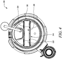
FIG. 4 shows a top view of the submersible pump illustrating the top element, in accordance with an aspect of the present disclosure; -
FIG. 5 shows a perspective view of the submersible pump illustrating a bottom element associated with the submersible pump, in accordance with an aspect of the present disclosure; and -
FIG. 6 shows a top view of the submersible pump illustrating the bottom element, in accordance with an aspect of the present disclosure. - The present disclosure will be described more fully hereinafter with reference to the accompanying drawings, in which example embodiments of the disclosure incorporating one or more aspects of the present disclosure are shown. This disclosure may, however, be embodied in many different forms and should not be construed as limited to the embodiments set forth herein; rather, these embodiments are provided so that this disclosure will be thorough and complete, and will fully convey the scope of the disclosure to those skilled in the art. For example, one or more aspects of the present disclosure may be utilized in other embodiments and even other types of structures and/or methods. In the drawings, like numbers refer to like elements.
- Certain terminology is used herein for convenience only and is not to be taken as a limitation on the disclosure. For example, "upper", "lower", "front", "rear", "side", "longitudinal", "lateral", "transverse", "upwards", "downwards", "forward", "backward", "sideward", "left," "right," "horizontal," "vertical," "upward", "inner", "outer", "inward", "outward", "top", "bottom", "higher", "above", "below", "central", "middle", "intermediate", "between", "end", "adjacent", "proximate", "near", "distal", "remote", "radial", "circumferential", or the like, merely describe the configuration shown in the Figures. Indeed, the components may be oriented in any direction and the terminology, therefore, should be understood as encompassing such variations unless specified otherwise.
-
FIG. 1 illustrates a perspective view of apump 100. The present disclosure relates to thepump 100. Thepump 100 is asubmersible pump 100. However, the present disclosure may be readily implemented with any pump as used or known in the art. Thepump 100 may be used in a number of fluid handling operations to pump a fluid. The fluid may include water or any other fluids having different viscosity. In an example, thepump 100 may include a multistage centrifugal pump, operating in a vertical position. - The
pump 100 includes apump housing 102. Thepump housing 102 is generally hollow and holds multiple components of thepump 100 therein. Thepump 100 includes a prime mover (not shown) that is disposed in thepump housing 102. The prime mover generates operational power and may include a hermetically sealed motor (not shown). Thepump housing 102 has aninlet 104 and anoutlet 106 for the fluid. The fluid is pumped in from theinlet 104 and pumped out from theoutlet 106. Theoutlet 106 is connected with ahose connector 108 which may allow connection of a hose (not shown) for pumping of the fluid. Thepump 100 may also include other components (not shown), such as an impeller, a shaft, a bearing, and the like. - As illustrated in
FIG. 2 , thepump 100 includes amechanism 110. Further, themechanism 110 incudes amovable basket 112. Themovable basket 112 is adapted to move between a first position "P1" (not shown) and a second position "P2", as illustrated in the accompanying figures. Themechanism 110 allows themovable basket 112 to switch between the first position "P1" and the second position "P2". The first position "P1" is an extended position of themovable basket 112. Further, the second position "P2" is a retracted position of themovable basket 112. The first and second positions "P1", "P2" of themovable basket 112 provides necessary changes in an inlet area of theinlet 104. Further, the first and second positions "P1", "P2", adjust theinlet 104 of thepump 100 to operate thepump 100 in a dirty water mode and a clean water mode. More particularly, the first and second positions "P1", "P2" of themovable basket 112 correspond to the dirty water mode and the clean water mode, respectively. As the dirty water mode requires larger inlet area to ensure efficient functioning of thepump 100 compared to the clean water mode, themovable basket 112 is moved to the first position "P1" for operating thepump 100 in the dirty water mode. - The operation of the
pump 100 in the first position "P1" allows handling of dirty water, wherein dirt particles of different sizes can enter without any obstruction. In order to switch to the first position "P1", themovable basket 112 moves within and relative to thepump housing 102. The movement of themovable basket 112 to the first position "P1" allows increase in an overall height of thepump 100. - The first position "P1" of the
movable basket 112 allows exposure of one or more inlet openings (not shown) provided on themovable basket 112. The inlet openings are disposed proximate to theinlet 104. In an example, thepump 100 may include a number of inverted "U" shaped inlet openings. However, the inlet openings may have any other shape, size, number, and dimensions, without any limitations. The first position "P1" and the second position "P2" of themovable basket 112 allow setup of thepump 100 for different applications as per desired size of the inlet openings, based on switching of themovable basket 112 between the first position "P1" and the second position "P2". - Further, the operation of
pump 100 in the second position "P2" allows handling of clean water. In the second position "P2", clean water may enter thepump 100 from theinlet 104. The second position "P2" of themovable basket 112 restricts a flow of any large sized particles. In order to switch to the second position "P2", themovable basket 112 moves relative and within thepump housing 102. The movement of themovable basket 112 to the second position "P2" allows to decrease the overall height of thepump 100. Moreover, in the second position "P2" of themovable basket 112, the inlet openings are partially or completely covered by thepump housing 102, as per application requirements. - Although the present disclosure discloses two positions, i.e. the first position "P1" and the second position "P2", an actual implementation of the present disclosure may have multiple number of positions of the
movable basket 112 between the first and second positions "P1", "P2". More particularly, themovable basket 112 may assume any other position between the first and second positions "P1", "P2". Moreover, the multiple positions may then allow multiple modes of operation of thepump 100. - Further, the
pump 100 includes apump body 114. Thepump body 114 or themechanism 110 may include any technique, means, components to allow movement and actuation of themovable basket 112 between the first and second positions "P1", "P2". Thepump 100 also includes ahandle 116 adapted to couple with thepump body 114. In some embodiments, handle 116 may be adapted to couple with thehousing 114, or any other part of thepump 100 without any limitation to the present disclosure. Thehandle 116 allows handling of thepump 100 by a user. Further, thehandle 116 works as a "trigger" for switching of themovable basket 112 between the first position "P1" and the second position "P2". Thehandle 116 includes afirst part 118 which defines atop element 120 and a bottom element 122 (best shown inFIG. 5 ). Further, actuation of thefirst part 118 of thehandle 116 is adapted to bias themovable basket 112 in one of the first position "P1" and the second position "P2". Thefirst part 118 works as an actuator to change the position of themovable basket 112. Further, thefirst part 118 of thehandle 116 may be actuated based on a touch, a push, a push and hold, and the like. In some embodiments, thehandle 116 may include additional parts or combination of parts to realize an intended function of actuating or triggering the movement of themovable basket 112. - The present disclosure relates to the
top element 120. Thetop element 120 will now be explained in detail.FIG. 3 illustrates a perspective view of thetop element 120 of thefirst part 118. It should be noted that the shape of thetop element 120 generally corresponds to a shape proximate to an upper portion 123 (seeFIG. 2 ) of the bottom element 122 (seeFIG. 2 ). Thetop element 120 includes a "C"-shaped design. However, thetop element 120 of thefirst part 118 may have any shape and size depending upon the design of thehandle 116 such that thetop element 120 covers a seating element 124 (seeFIGS. 4 ,5 , and6 ). - A material of the
top element 120 may include plastic, metal, wood, and the like. Thetop element 120 defines afirst end 126 and asecond end 128. Thetop element 120 defines aninner surface 129 and anouter surface 131 that is opposite to theinner surface 129. Further, thetop element 120 includes afirst hole 130 defined at thefirst end 126 and asecond hole 132 defined at thesecond end 128. Thefirst hole 130 is in alignment with thesecond hole 132. In the illustrated embodiment, the first andsecond holes second holes top element 120 may include any number of holes with various shapes and sizes, without limiting the scope of the present disclosure. In the illustrated example, the first andsecond holes top element 120 may include a pair of protrusions, grooves or any other connecting elements projecting from theouter surface 131 or theinner surface 129 of thetop element 120 to engage with corresponding mating elements on thebottom element 122. - Further, the
top element 120 includes a pair ofside portions 134, only one of which is illustrated herein. In some examples, the pair ofside portions 134 may be parallel to each other. In other examples, eachside portion 134 may be angularly disposed, such that the pair ofside portions 134 are not parallel to each other. Moreover, thetop element 120 defines anopening 135 to accommodate thebottom element 122 when thetop element 120 is coupled to thebottom element 122 and theseating element 124. Further, a length "L" defined by thetop element 120 may be substantially equal to or slightly greater than a distance between left andright arms - As shown in
FIG. 2 , thehandle 116 defines theleft arm 136 and theright arm 138, wherein thetop element 120 of thefirst part 118 removably couples (or say clicks) on one or more of theleft arm 136 and theright arm 138. The left andright arms bottom element 122. Thebottom element 122 includes a generally inverted "U"-shaped design. In some embodiments, thebottom element 122 is designed like a bridge with theleft arm 136 and theright arm 138. This allows thebottom element 122 to allow easy and stable coupling with thetop element 120. A material of thebottom element 122 may include plastic, metal, wood, and the like. In some embodiments, removal of thetop element 120 may allow assembly or disassembly of different parts or components of themechanism 110, or of thepump 100. More particularly, removal of thetop element 120 may allow assembly or disassembly of the left andright arms handle 116. Such a simple, and easily removal arrangement of thetop element 120 may thus allow effective and user-friendly cleaning in situ, or even after taking the parts or components outside of thehandle 116. - The
left arm 136 and theright arm 138 of thebottom element 122 extend downwards towards theinlet 104 of thepump 100. Theleft arm 136 and theright arm 138 of thehandle 116 are adapted to at least partially engage with themechanism 110 of thepump 100. The engagement of the left andright arms mechanism 110 may allow switching of themovable basket 112 between the first and second positions "P1", "P2", based on the actuation of thefirst part 118 of thehandle 116. - The
bottom element 122 of thefirst part 118 includes a first engaging element 140 (shown inFIG. 5 ) and a second engaging element 142 (shown inFIG. 2 ). The firstengaging element 140 is disposed on theleft arm 136, whereas the secondengaging element 142 is disposed on theright arm 138. Further, the firstengaging element 140 engages with the first hole 130 (seeFIG. 3 ) of thetop element 120 and the secondengaging element 142 engages with the second hole 132 (seeFIG. 3 ) of thetop element 120 to secure thetop element 120 with thebottom element 122. A shape and a size of the first and secondengaging elements second holes engaging element 140 and the secondengaging element 142 are circular in shape. Alternatively, the first and secondengaging elements - Further, the first and second
engaging elements engaging elements right arms engaging elements engaging elements top element 120 with thebottom element 122. Although thebottom element 122 includes twoengaging elements engaging elements holes top element 120. - Referring to
FIGS. 4 and5 , thehandle 116 also includes asecond part 144 which defines theseating element 124. Further, either theseating element 124 of thesecond part 144 at least partially covers thetop element 120 of thefirst part 118, or thetop element 120 of thefirst part 118 at least partially covers theseating element 124 of thesecond part 144. More particularly, in an example, theseating element 124 is designed to partially or totally cover thetop element 120, such that there is no gap between theseating element 124 and thetop element 120. The present disclosure illustrates theseating element 124 partially covering theside portions 134 of the top element 120 (as best shown inFIG. 1 ). This will allow theseating element 124 to disallow any foreign particles to move between theseating element 124 and thetop element 120. In another example, thetop element 120 is designed to partially or totally cover theseating element 124, such that there is no gap between theseating element 124 and thetop element 120. This arrangement of thetop element 120 and theseating element 124 limits any gaps between thetop element 120 and theseating element 124 to avoid penetration of any foreign particles therethrough. It should be noted that thebottom element 122 of thefirst part 118 is disposed between thetop element 120 and theseating element 124. - The
first part 118 is movable relative to thesecond part 144. Further, movement of thefirst part 118 relative to thesecond part 144 allows actuation of themechanism 110, based on the user's action on thetop element 120 of thefirst part 118. In some examples, theseating element 124 of thesecond part 144 may at least partially receive thefirst part 118 when themovable basket 112 is in the second position "P2". In an embodiment, thesecond part 144 may be fixed to thepump housing 102. - Further, the
first part 118 is coupled with thesecond part 144, such that thetop element 120 of thefirst part 118 is removable therefrom. As shown inFIGS. 5 and6 , when thetop element 120 is removed, agap 146 exists between thebottom element 122 and thesecond part 144. Further, when thetop element 120 is coupled to thebottom element 122, the pair ofside portions 134 may cover thegap 146. Removal of thetop element 120 of thefirst part 118 allows access to theseating element 124 of thesecond part 144. Further, thefirst part 118 and thesecond part 144 may be removably coupled by one or more of a screws, a snap-fit, and pins, in some embodiments. In the illustrated embodiment, thefirst part 118 and thesecond part 144 are removably coupled by a snap fit arrangement. Alternatively, thefirst part 118 and thesecond part 144 may be removably coupled by any other means generally used or known in the art. - The present disclosure provides improvement in the
handle 116 for thepump 100, which is preferably thesubmersible pump 100. Thefirst part 118 and thesecond part 144 are designed in such a way that the user may easily grip thehandle 116 for movement of thepump 100 or cleaning and other maintenance purposes. The parts of thehandle 116 described herein are designed ergonomically so that the user may comfortably actuate thetop element 120 of thefirst part 118 to switch the position of themovable basket 112 between the first position "P1" and the second position "P2". Further, the present disclosure may be readily applicable with any other multiple part arrangement of thepump 100, even other than thehandle 116. The techniques of the present disclosure may be easily applied with different movable parts of themechanism 110, particularly parts which are susceptible to intrusion of foreign particles. - Further, the
handle 116 includes thetop element 120 that is removably coupled to thebottom element 122. Thetop element 120 includes a simple design and is a cost-effective component. Moreover, thetop element 120 restricts passage and settling of foreign particles in theseating element 124. Removal of thetop element 120 provides ease in accessibility to theseating element 124 for cleaning thereof. Further, the removable coupling arrangement of thetop element 120 with thebottom element 122 provides quick and easy attachment/detachment of thetop element 120 with thebottom element 122. - In the drawings and specification, there have been disclosed preferred embodiments and examples of the disclosure and, although specific terms are employed, they are used in a generic and descriptive sense only and not for the purpose of limitation of the scope of the disclosure being set forth in the following claims.
-
- 100
- Pump
- 102
- Pump Housing
- 104
- Inlet
- 106
- Outlet
- 108
- Hose Connector
- 110
- Mechanism
- 112
- Movable Basket
- 114
- Pump Body
- 116
- Handle
- 118
- First Part
- 120
- Top Element
- 122
- Bottom Element
- 123
- Upper Portion
- 124
- Seating Element
- 126
- First End
- 128
- Second End
- 129
- Inner Surface
- 130
- First Hole
- 131
- Outer Surface
- 132
- Second Hole
- 134
- Side Portions
- 135
- Opening
- 136
- Left Arm
- 138
- Right Arm
- 140
- First Engaging Element
- 142
- Second Engaging Element
- 144
- Second Part
- P1
- First Position
- P2
- Second Position
- L
- Length
Claims (8)
- A pump (100) comprising:a pump body (114), anda handle (116) adapted to couple with the pump body (114), the handle (116) comprising:a first part (118) which defines a top element (120) and a bottom element (122); anda second part (144) which defines a seating element (124), wherein either the seating element (124) of the second part (144) at least partially covers the top element (120) of the first part (118), or the top element (120) of the first part (118) at least partially covers the seating element (124) of the second part (144), andwherein the first part (118) and the second part (144) are movable relative to each other;characterized in that:
the first part (118) is coupled with the second part (144) such that the top element (120) of the first part (118) is removable therefrom. - The pump (100) of claim 1, wherein removal of the top element (120) of the first part (118) allows access to the seating element (124) of the second part (144).
- The pump (100) of claim 1, wherein the first part (118) and the second part (144) are removably coupled by one or more of a screws, a snap-fit, and pins.
- The pump (100) of claim 3, wherein the handle (116) defines a left arm (136) and a right arm (138), wherein the top element (120) of the first part (118) removably couples on one or more of the left arm (136) and the right arm (138).
- The pump (100) of claim 4, wherein the left arm (136) and the right arm (138) of the handle (116) are adapted to at least partially engage with a mechanism (110) of the pump (100).
- The pump (100) of claim 1, wherein the pump (100) further includes a movable basket (114) adapted to move between a first position (P1) and a second position (P2), wherein actuation of the first part (118) of the handle (116) is adapted to bias the movable basket (114) in one of the first position (P1) and the second position (P2).
- The pump (100) of claim 5 and 6, wherein the mechanism (110) includes the movable basket (114).
- The pump (100) of any of the preceding claims, wherein the pump (100) is a submersible pump (100).
Priority Applications (4)
| Application Number | Priority Date | Filing Date | Title |
|---|---|---|---|
| EP20204388.1A EP3992464A1 (en) | 2020-10-28 | 2020-10-28 | Pump and handle associated with pump |
| CN202180073903.0A CN116472409B (en) | 2020-10-28 | 2021-06-02 | Pumps and pump-related handles |
| PCT/EP2021/064799 WO2022089785A1 (en) | 2020-10-28 | 2021-06-02 | Pump and handle associated with pump |
| EP21730201.7A EP4204690A1 (en) | 2020-10-28 | 2021-06-02 | Pump and handle associated with pump |
Applications Claiming Priority (1)
| Application Number | Priority Date | Filing Date | Title |
|---|---|---|---|
| EP20204388.1A EP3992464A1 (en) | 2020-10-28 | 2020-10-28 | Pump and handle associated with pump |
Publications (1)
| Publication Number | Publication Date |
|---|---|
| EP3992464A1 true EP3992464A1 (en) | 2022-05-04 |
Family
ID=73037804
Family Applications (2)
| Application Number | Title | Priority Date | Filing Date |
|---|---|---|---|
| EP20204388.1A Withdrawn EP3992464A1 (en) | 2020-10-28 | 2020-10-28 | Pump and handle associated with pump |
| EP21730201.7A Pending EP4204690A1 (en) | 2020-10-28 | 2021-06-02 | Pump and handle associated with pump |
Family Applications After (1)
| Application Number | Title | Priority Date | Filing Date |
|---|---|---|---|
| EP21730201.7A Pending EP4204690A1 (en) | 2020-10-28 | 2021-06-02 | Pump and handle associated with pump |
Country Status (3)
| Country | Link |
|---|---|
| EP (2) | EP3992464A1 (en) |
| CN (1) | CN116472409B (en) |
| WO (1) | WO2022089785A1 (en) |
Cited By (1)
| Publication number | Priority date | Publication date | Assignee | Title |
|---|---|---|---|---|
| FR3153839A1 (en) * | 2023-10-05 | 2025-04-11 | Magiflex | REMOVABLE FLANGE TOOL FOR A POOL MAINTENANCE PUMP |
Citations (3)
| Publication number | Priority date | Publication date | Assignee | Title |
|---|---|---|---|---|
| CN204226273U (en) * | 2014-09-03 | 2015-03-25 | 君禾泵业股份有限公司 | The telescopic handle structure of compact submersible pump |
| WO2020098965A1 (en) * | 2018-11-14 | 2020-05-22 | Husqvarna Ab | Fluid pump |
| CN210961650U (en) | 2019-07-15 | 2020-07-10 | 九阳股份有限公司 | Low-noise food processor |
Family Cites Families (2)
| Publication number | Priority date | Publication date | Assignee | Title |
|---|---|---|---|---|
| WO2018162044A1 (en) * | 2017-03-07 | 2018-09-13 | Husqvarna Ab | Submersible pump |
| CN207393499U (en) * | 2017-08-31 | 2018-05-22 | 利欧集团浙江泵业有限公司 | Immersible pump |
-
2020
- 2020-10-28 EP EP20204388.1A patent/EP3992464A1/en not_active Withdrawn
-
2021
- 2021-06-02 CN CN202180073903.0A patent/CN116472409B/en active Active
- 2021-06-02 WO PCT/EP2021/064799 patent/WO2022089785A1/en not_active Ceased
- 2021-06-02 EP EP21730201.7A patent/EP4204690A1/en active Pending
Patent Citations (3)
| Publication number | Priority date | Publication date | Assignee | Title |
|---|---|---|---|---|
| CN204226273U (en) * | 2014-09-03 | 2015-03-25 | 君禾泵业股份有限公司 | The telescopic handle structure of compact submersible pump |
| WO2020098965A1 (en) * | 2018-11-14 | 2020-05-22 | Husqvarna Ab | Fluid pump |
| CN210961650U (en) | 2019-07-15 | 2020-07-10 | 九阳股份有限公司 | Low-noise food processor |
Cited By (1)
| Publication number | Priority date | Publication date | Assignee | Title |
|---|---|---|---|---|
| FR3153839A1 (en) * | 2023-10-05 | 2025-04-11 | Magiflex | REMOVABLE FLANGE TOOL FOR A POOL MAINTENANCE PUMP |
Also Published As
| Publication number | Publication date |
|---|---|
| CN116472409B (en) | 2025-12-05 |
| CN116472409A (en) | 2023-07-21 |
| EP4204690A1 (en) | 2023-07-05 |
| WO2022089785A1 (en) | 2022-05-05 |
Similar Documents
| Publication | Publication Date | Title |
|---|---|---|
| RU2271134C1 (en) | Vacuum cleaner and suction channel unit for the same | |
| EP3943688B1 (en) | Underwater sewage suction machine | |
| US20100232990A1 (en) | Centrifugal discharge pump with bladed impeller for dishwashers and similar electric household appliances | |
| CN106955807A (en) | Integrated pump guard and control interlock | |
| US5850668A (en) | Self-evacuating vacuum cleaner | |
| EP4204690A1 (en) | Pump and handle associated with pump | |
| EP3880964B1 (en) | Fluid pump | |
| US10973381B2 (en) | Vacuum cleaner | |
| EP3875825A1 (en) | Connector for a pump | |
| EP4226046B1 (en) | Mechanism for pump | |
| KR100232275B1 (en) | Pump device | |
| US11197594B2 (en) | Cleaner | |
| CA2585171A1 (en) | Impeller wheel | |
| EP1174071B1 (en) | Pump inlet fitting | |
| CN112790699B (en) | Cleaning machine | |
| RU2258450C1 (en) | Cyclone-type vacuum cleaner (versions) | |
| CN111836931B (en) | Material collection equipment | |
| KR100227191B1 (en) | An up-right vacuum cleaner | |
| CN219366417U (en) | Fan with fan body | |
| CN214259203U (en) | Sweeping robot | |
| KR102963227B1 (en) | Spurt pump with cutting function | |
| CN217938153U (en) | Spray arm and dish washing machine | |
| CN219940525U (en) | Cleaning barrel and cleaning tool | |
| CN213850534U (en) | Flow guide cover and cleaning tool thereof | |
| EP3875766A1 (en) | Foot for a pump |
Legal Events
| Date | Code | Title | Description |
|---|---|---|---|
| PUAI | Public reference made under article 153(3) epc to a published international application that has entered the european phase |
Free format text: ORIGINAL CODE: 0009012 |
|
| STAA | Information on the status of an ep patent application or granted ep patent |
Free format text: STATUS: THE APPLICATION HAS BEEN PUBLISHED |
|
| AK | Designated contracting states |
Kind code of ref document: A1 Designated state(s): AL AT BE BG CH CY CZ DE DK EE ES FI FR GB GR HR HU IE IS IT LI LT LU LV MC MK MT NL NO PL PT RO RS SE SI SK SM TR |
|
| STAA | Information on the status of an ep patent application or granted ep patent |
Free format text: STATUS: THE APPLICATION HAS BEEN WITHDRAWN |
|
| 18W | Application withdrawn |
Effective date: 20220811 |