EP3992448A1 - Engine exhaust gas recirculation system, multi-cylinder engine, and vehicle - Google Patents
Engine exhaust gas recirculation system, multi-cylinder engine, and vehicle Download PDFInfo
- Publication number
- EP3992448A1 EP3992448A1 EP21204164.4A EP21204164A EP3992448A1 EP 3992448 A1 EP3992448 A1 EP 3992448A1 EP 21204164 A EP21204164 A EP 21204164A EP 3992448 A1 EP3992448 A1 EP 3992448A1
- Authority
- EP
- European Patent Office
- Prior art keywords
- egr
- engine
- cylinder
- exhaust
- pipe
- Prior art date
- Legal status (The legal status is an assumption and is not a legal conclusion. Google has not performed a legal analysis and makes no representation as to the accuracy of the status listed.)
- Withdrawn
Links
Images




Classifications
-
- F—MECHANICAL ENGINEERING; LIGHTING; HEATING; WEAPONS; BLASTING
- F02—COMBUSTION ENGINES; HOT-GAS OR COMBUSTION-PRODUCT ENGINE PLANTS
- F02M—SUPPLYING COMBUSTION ENGINES IN GENERAL WITH COMBUSTIBLE MIXTURES OR CONSTITUENTS THEREOF
- F02M26/00—Engine-pertinent apparatus for adding exhaust gases to combustion-air, main fuel or fuel-air mixture, e.g. by exhaust gas recirculation [EGR] systems
- F02M26/13—Arrangement or layout of EGR passages, e.g. in relation to specific engine parts or for incorporation of accessories
- F02M26/14—Arrangement or layout of EGR passages, e.g. in relation to specific engine parts or for incorporation of accessories in relation to the exhaust system
-
- F—MECHANICAL ENGINEERING; LIGHTING; HEATING; WEAPONS; BLASTING
- F01—MACHINES OR ENGINES IN GENERAL; ENGINE PLANTS IN GENERAL; STEAM ENGINES
- F01N—GAS-FLOW SILENCERS OR EXHAUST APPARATUS FOR MACHINES OR ENGINES IN GENERAL; GAS-FLOW SILENCERS OR EXHAUST APPARATUS FOR INTERNAL-COMBUSTION ENGINES
- F01N13/00—Exhaust or silencing apparatus characterised by constructional features
- F01N13/08—Other arrangements or adaptations of exhaust conduits
- F01N13/10—Other arrangements or adaptations of exhaust conduits of exhaust manifolds
-
- F—MECHANICAL ENGINEERING; LIGHTING; HEATING; WEAPONS; BLASTING
- F01—MACHINES OR ENGINES IN GENERAL; ENGINE PLANTS IN GENERAL; STEAM ENGINES
- F01N—GAS-FLOW SILENCERS OR EXHAUST APPARATUS FOR MACHINES OR ENGINES IN GENERAL; GAS-FLOW SILENCERS OR EXHAUST APPARATUS FOR INTERNAL-COMBUSTION ENGINES
- F01N13/00—Exhaust or silencing apparatus characterised by constructional features
- F01N13/14—Exhaust or silencing apparatus characterised by constructional features having thermal insulation
-
- F—MECHANICAL ENGINEERING; LIGHTING; HEATING; WEAPONS; BLASTING
- F01—MACHINES OR ENGINES IN GENERAL; ENGINE PLANTS IN GENERAL; STEAM ENGINES
- F01N—GAS-FLOW SILENCERS OR EXHAUST APPARATUS FOR MACHINES OR ENGINES IN GENERAL; GAS-FLOW SILENCERS OR EXHAUST APPARATUS FOR INTERNAL-COMBUSTION ENGINES
- F01N13/00—Exhaust or silencing apparatus characterised by constructional features
- F01N13/18—Construction facilitating manufacture, assembly, or disassembly
- F01N13/1805—Fixing exhaust manifolds, exhaust pipes or pipe sections to each other, to engine or to vehicle body
-
- F—MECHANICAL ENGINEERING; LIGHTING; HEATING; WEAPONS; BLASTING
- F02—COMBUSTION ENGINES; HOT-GAS OR COMBUSTION-PRODUCT ENGINE PLANTS
- F02B—INTERNAL-COMBUSTION PISTON ENGINES; COMBUSTION ENGINES IN GENERAL
- F02B75/00—Other engines
- F02B75/02—Engines characterised by their cycles, e.g. six-stroke
-
- F—MECHANICAL ENGINEERING; LIGHTING; HEATING; WEAPONS; BLASTING
- F02—COMBUSTION ENGINES; HOT-GAS OR COMBUSTION-PRODUCT ENGINE PLANTS
- F02B—INTERNAL-COMBUSTION PISTON ENGINES; COMBUSTION ENGINES IN GENERAL
- F02B75/00—Other engines
- F02B75/16—Engines characterised by number of cylinders, e.g. single-cylinder engines
- F02B75/18—Multi-cylinder engines
- F02B75/20—Multi-cylinder engines with cylinders all in one line
-
- F—MECHANICAL ENGINEERING; LIGHTING; HEATING; WEAPONS; BLASTING
- F02—COMBUSTION ENGINES; HOT-GAS OR COMBUSTION-PRODUCT ENGINE PLANTS
- F02M—SUPPLYING COMBUSTION ENGINES IN GENERAL WITH COMBUSTIBLE MIXTURES OR CONSTITUENTS THEREOF
- F02M26/00—Engine-pertinent apparatus for adding exhaust gases to combustion-air, main fuel or fuel-air mixture, e.g. by exhaust gas recirculation [EGR] systems
- F02M26/01—Internal exhaust gas recirculation, i.e. wherein the residual exhaust gases are trapped in the cylinder or pushed back from the intake or the exhaust manifold into the combustion chamber without the use of additional passages
-
- F—MECHANICAL ENGINEERING; LIGHTING; HEATING; WEAPONS; BLASTING
- F02—COMBUSTION ENGINES; HOT-GAS OR COMBUSTION-PRODUCT ENGINE PLANTS
- F02M—SUPPLYING COMBUSTION ENGINES IN GENERAL WITH COMBUSTIBLE MIXTURES OR CONSTITUENTS THEREOF
- F02M26/00—Engine-pertinent apparatus for adding exhaust gases to combustion-air, main fuel or fuel-air mixture, e.g. by exhaust gas recirculation [EGR] systems
- F02M26/13—Arrangement or layout of EGR passages, e.g. in relation to specific engine parts or for incorporation of accessories
- F02M26/14—Arrangement or layout of EGR passages, e.g. in relation to specific engine parts or for incorporation of accessories in relation to the exhaust system
- F02M26/15—Arrangement or layout of EGR passages, e.g. in relation to specific engine parts or for incorporation of accessories in relation to the exhaust system in relation to engine exhaust purifying apparatus
-
- F—MECHANICAL ENGINEERING; LIGHTING; HEATING; WEAPONS; BLASTING
- F02—COMBUSTION ENGINES; HOT-GAS OR COMBUSTION-PRODUCT ENGINE PLANTS
- F02M—SUPPLYING COMBUSTION ENGINES IN GENERAL WITH COMBUSTIBLE MIXTURES OR CONSTITUENTS THEREOF
- F02M26/00—Engine-pertinent apparatus for adding exhaust gases to combustion-air, main fuel or fuel-air mixture, e.g. by exhaust gas recirculation [EGR] systems
- F02M26/13—Arrangement or layout of EGR passages, e.g. in relation to specific engine parts or for incorporation of accessories
- F02M26/17—Arrangement or layout of EGR passages, e.g. in relation to specific engine parts or for incorporation of accessories in relation to the intake system
- F02M26/18—Thermal insulation or heat protection
-
- F—MECHANICAL ENGINEERING; LIGHTING; HEATING; WEAPONS; BLASTING
- F02—COMBUSTION ENGINES; HOT-GAS OR COMBUSTION-PRODUCT ENGINE PLANTS
- F02M—SUPPLYING COMBUSTION ENGINES IN GENERAL WITH COMBUSTIBLE MIXTURES OR CONSTITUENTS THEREOF
- F02M26/00—Engine-pertinent apparatus for adding exhaust gases to combustion-air, main fuel or fuel-air mixture, e.g. by exhaust gas recirculation [EGR] systems
- F02M26/13—Arrangement or layout of EGR passages, e.g. in relation to specific engine parts or for incorporation of accessories
- F02M26/22—Arrangement or layout of EGR passages, e.g. in relation to specific engine parts or for incorporation of accessories with coolers in the recirculation passage
-
- F—MECHANICAL ENGINEERING; LIGHTING; HEATING; WEAPONS; BLASTING
- F02—COMBUSTION ENGINES; HOT-GAS OR COMBUSTION-PRODUCT ENGINE PLANTS
- F02M—SUPPLYING COMBUSTION ENGINES IN GENERAL WITH COMBUSTIBLE MIXTURES OR CONSTITUENTS THEREOF
- F02M26/00—Engine-pertinent apparatus for adding exhaust gases to combustion-air, main fuel or fuel-air mixture, e.g. by exhaust gas recirculation [EGR] systems
- F02M26/13—Arrangement or layout of EGR passages, e.g. in relation to specific engine parts or for incorporation of accessories
- F02M26/22—Arrangement or layout of EGR passages, e.g. in relation to specific engine parts or for incorporation of accessories with coolers in the recirculation passage
- F02M26/23—Layout, e.g. schematics
-
- F—MECHANICAL ENGINEERING; LIGHTING; HEATING; WEAPONS; BLASTING
- F02—COMBUSTION ENGINES; HOT-GAS OR COMBUSTION-PRODUCT ENGINE PLANTS
- F02M—SUPPLYING COMBUSTION ENGINES IN GENERAL WITH COMBUSTIBLE MIXTURES OR CONSTITUENTS THEREOF
- F02M26/00—Engine-pertinent apparatus for adding exhaust gases to combustion-air, main fuel or fuel-air mixture, e.g. by exhaust gas recirculation [EGR] systems
- F02M26/13—Arrangement or layout of EGR passages, e.g. in relation to specific engine parts or for incorporation of accessories
- F02M26/22—Arrangement or layout of EGR passages, e.g. in relation to specific engine parts or for incorporation of accessories with coolers in the recirculation passage
- F02M26/29—Constructional details of the coolers, e.g. pipes, plates, ribs, insulation or materials
- F02M26/30—Connections of coolers to other devices, e.g. to valves, heaters, compressors or filters; Coolers characterised by their location on the engine
-
- F—MECHANICAL ENGINEERING; LIGHTING; HEATING; WEAPONS; BLASTING
- F02—COMBUSTION ENGINES; HOT-GAS OR COMBUSTION-PRODUCT ENGINE PLANTS
- F02M—SUPPLYING COMBUSTION ENGINES IN GENERAL WITH COMBUSTIBLE MIXTURES OR CONSTITUENTS THEREOF
- F02M26/00—Engine-pertinent apparatus for adding exhaust gases to combustion-air, main fuel or fuel-air mixture, e.g. by exhaust gas recirculation [EGR] systems
- F02M26/13—Arrangement or layout of EGR passages, e.g. in relation to specific engine parts or for incorporation of accessories
- F02M26/41—Arrangement or layout of EGR passages, e.g. in relation to specific engine parts or for incorporation of accessories characterised by the arrangement of the recirculation passage in relation to the engine, e.g. to cylinder heads, liners, spark plugs or manifolds; characterised by the arrangement of the recirculation passage in relation to specially adapted combustion chambers
-
- F—MECHANICAL ENGINEERING; LIGHTING; HEATING; WEAPONS; BLASTING
- F02—COMBUSTION ENGINES; HOT-GAS OR COMBUSTION-PRODUCT ENGINE PLANTS
- F02B—INTERNAL-COMBUSTION PISTON ENGINES; COMBUSTION ENGINES IN GENERAL
- F02B75/00—Other engines
- F02B75/02—Engines characterised by their cycles, e.g. six-stroke
- F02B2075/022—Engines characterised by their cycles, e.g. six-stroke having less than six strokes per cycle
- F02B2075/027—Engines characterised by their cycles, e.g. six-stroke having less than six strokes per cycle four
-
- F—MECHANICAL ENGINEERING; LIGHTING; HEATING; WEAPONS; BLASTING
- F02—COMBUSTION ENGINES; HOT-GAS OR COMBUSTION-PRODUCT ENGINE PLANTS
- F02B—INTERNAL-COMBUSTION PISTON ENGINES; COMBUSTION ENGINES IN GENERAL
- F02B75/00—Other engines
- F02B75/16—Engines characterised by number of cylinders, e.g. single-cylinder engines
- F02B75/18—Multi-cylinder engines
- F02B2075/1804—Number of cylinders
- F02B2075/1816—Number of cylinders four
-
- Y—GENERAL TAGGING OF NEW TECHNOLOGICAL DEVELOPMENTS; GENERAL TAGGING OF CROSS-SECTIONAL TECHNOLOGIES SPANNING OVER SEVERAL SECTIONS OF THE IPC; TECHNICAL SUBJECTS COVERED BY FORMER USPC CROSS-REFERENCE ART COLLECTIONS [XRACs] AND DIGESTS
- Y02—TECHNOLOGIES OR APPLICATIONS FOR MITIGATION OR ADAPTATION AGAINST CLIMATE CHANGE
- Y02T—CLIMATE CHANGE MITIGATION TECHNOLOGIES RELATED TO TRANSPORTATION
- Y02T10/00—Road transport of goods or passengers
- Y02T10/10—Internal combustion engine [ICE] based vehicles
- Y02T10/12—Improving ICE efficiencies
Definitions
- the present disclosure relates to an exhaust gas recirculation system for an engine.
- JP2015-124692A discloses an EGR system which takes out, as EGR gas, part of the exhaust gas from an exhaust pipe which is located downstream of a catalyst for purifying the exhaust gas.
- an EGR cooler which cools the EGR gas is disposed near the catalyst.
- the exhaust pipe which is located downstream of the catalyst is connected with the EGR cooler via a "short" upstream EGR pipe.
- the EGR cooler is connected with an "in-head" EGR passage which passes through the inside of a cylinder head via a downstream EGR pipe.
- the present disclosure copes with the heat damage which an exhaust gas recirculation (EGR) pipe receives from exhaust gas.
- EGR exhaust gas recirculation
- an EGR pipe extending from an EGR gas outlet provided downstream of a catalyst is directly connected to an in-head EGR passage, without being intervened by an EGR cooler.
- an exhaust gas recirculation system for a multi-cylinder engine which includes an exhaust manifold connected to a cylinder head of the engine and configured to collect exhaust gas discharged from each cylinder of the engine, a catalyst connected to a downstream end of the exhaust manifold with respect to an exhaust gas flow and configured to purify the exhaust gas, an EGR gas outlet provided downstream of the catalyst and configured to take out part of the exhaust gas as EGR gas to be recirculated to an intake side of the engine, an in-head EGR passage penetrating the cylinder head and through which the EGR gas passes, and an EGR pipe extending from the EGR gas outlet and configured to lead the EGR gas to the in-head EGR passage.
- the catalyst is disposed so that the exhaust gas flows inside the catalyst from a first side to a second side in a cylinder lined-up direction of the engine.
- the EGR gas outlet is located on the second side with respect to the center of the engine in the cylinder lined-up direction.
- An inlet of the in-head EGR passage is located in the first side with respect to the center of the engine in the cylinder lined-up direction.
- the EGR pipe extending from the EGR gas outlet is directly connected to the inlet of the in-head EGR passage.
- the length of the EGR pipe extending from the EGR gas outlet to the inlet of the in-head EGR passage can be made longer than a case where the EGR pipe is connected to an EGR cooler. Therefore, even if hot exhaust gas is introduced from the EGR gas outlet into the EGR pipe, a heat release amount in the middle of the EGR pipe reaching to the inlet of the in-head EGR passage becomes larger. Thus, compared to when the pipe length is short, an elongation of the entire pipe becomes smaller, and a great increase in the temperature near the inlet of the in-head EGR passage is also avoided.
- the EGR gas outlet may open toward the second side in the cylinder lined-up direction.
- the EGR pipe may have a bend configured to change a flow direction of the EGR gas so that the EGR gas flowing from the EGR gas outlet to the second side flows to the first side in the cylinder lined-up direction where the inlet of the in-head EGR passage exists.
- the EGR pipe becomes longer by being provided with the bend, and heat release area becomes accordingly larger. Therefore, it is advantageous in avoiding the temperature increase in the EGR pipe near the inlet of the in-head EGR passage.
- the EGR pipe may have a larger passage cross-sectional area at the bend than at a downstream part extending continuously from the bend to the inlet of the in-head EGR passage.
- the exhaust gas recirculation system may further include a heat insulator covering the exhaust manifold and the catalyst.
- the EGR pipe may be disposed inside the heat insulator.
- the temperature of the EGR pipe is controlled with the layout of the EGR pipe and the heat insulator so that, during the operation of the engine, damage of the EGR pipe at the connecting part to the in-head EGR passage is prevented, and while the engine is stopped, the generation of condensate water is prevented.
- the engine may be an inline four-cylinder four-cycle engine.
- the exhaust manifold may be a 4-2-1 type.
- the exhaust manifold may be provided with a first collecting pipe where independent exhaust pipes leading to two center cylinders in the cylinder lined-up direction of the engine are collected, a second collecting pipe where independent exhaust pipes leading to two end cylinders in the cylinder lined-up direction of the engine are collected, and a third collecting pipe where the first collecting pipe and the second collecting pipe are collected.
- the engine may be configured with an exhaust order of the four cylinders so that exhaust timings of the two center cylinders do not overlap with each other and exhaust timings of the two end cylinders do not overlap with each other.
- the catalyst may be connected to the third collecting pipe.
- an inversion of exhaust pressure wave occurs at each collected part of the first collecting pipe and the second collecting pipe (merging section of the independent exhaust pipes), and an inversion of exhaust pressure wave also occurs at a collected part of the third collecting pipe.
- exhaust timings of the two cylinders to which each of the first collecting pipe and the second collecting pipe is connected do not overlap, exhaust interference does not occur.
- the inversion of exhaust pressure wave at the collected part of the third collecting pipe may lead to exhaust interference, it has only a small influence on the exhaust gas to be discharged from the cylinders. In this manner, by adopting the 4-2-1 type manifold, the exhaust interference is suppressed and exhaust gas becomes more easily discharged from each cylinder, which is advantageous to stabilize and optimize the EGR.
- the exhaust gas recirculation system may further include an EGR cooler configured to cool the EGR gas.
- the EGR cooler may be disposed in the engine on the intake side opposite to an exhaust side where the exhaust manifold is disposed, and the EGR gas that passes through the in-head EGR passage may then be introduced into the EGR cooler.
- the vibration from the EGR cooler is difficult to propagate to the EGR pipe, which is advantageous in preventing damage of the EGR pipe.
- a multi-cylinder engine includes the above exhaust gas recirculation system.
- a vehicle includes the above multi-cylinder engine.
- An engine 1 illustrated in Fig. 1 is a multi-cylinder engine which drives a vehicle (particularly an automobile), and in this example, is an inline four-cylinder four-cycle engine.
- the engine 1 particularly includes a cylinder block 2, a cylinder head 3 which is coupled to an upper surface of the cylinder block 2, an oil pan 4 coupled to a lower surface of the cylinder block 2, and a cylinder head cover 9 fixed onto the cylinder head 3.
- the engine 1 is particularly mounted to a front part of the vehicle, which is a so-called "transverse engine” in which the cylinder lined-up direction is oriented substantially in a vehicle width direction.
- An arrow F of Fig. 1 indicates front or forward of the vehicle, and an arrow R indicates rear or rearward of the vehicle. The same will be applied to other drawings.
- An intake manifold is particularly disposed forward of the engine 1, and an exhaust manifold 5 is particularly disposed rearward of the engine 1.
- Intake air is introduced from the intake manifold into an intake port of each cylinder which opens to a forward side surface of the cylinder head 3.
- Exhaust gas which is generated inside a combustion chamber of each cylinder is discharged to the exhaust manifold 5 from an exhaust port of each cylinder which opens to a rearward side surface of the cylinder head 3.
- the engine 1 is particularly a front-intake rear-exhaust engine in which the front side is an intake side and the rear side is an exhaust side.
- an upstream end means an upstream end of an exhaust gas flow or an exhaust gas recirculation (EGR) gas flow
- a “downstream end” means a downstream end of the exhaust gas flow or the EGR gas flow.
- the exhaust manifold 5 is particularly provided with a first collecting pipe 6, a second collecting pipe 7, and a third collecting pipe 8.
- the first collecting pipe 6 is tubing which collects independent exhaust pipes 12 and 13 which lead to two center cylinders in the cylinder lined-up direction of the engine 1.
- the second collecting pipe 7 is tubing which collects independent exhaust pipes 11 and 14 which lead to two cylinders at both ends in the cylinder lined-up direction of the engine 1.
- the third collecting pipe 8 is tubing which collects the first collecting pipe 6 and the second collecting pipe 7. That is, the exhaust manifold 5 is particularly a 4-2-1 type manifold.
- the exhaust order of the four cylinders is particularly defined so that exhaust timings of the two center cylinders do not overlap with each other and exhaust timings of the two end cylinders do not overlap with each other.
- the cylinder at the left end is called a first cylinder and other cylinders lined up to the right side are called a second cylinder, a third cylinder, and a fourth cylinder, respectively
- exhaust gas flows in the order of the first cylinder, the third cylinder, the fourth cylinder, and the second cylinder.
- Exhaust interference is suppressed by increasing the distance from the exhaust port of each cylinder to the collected location of the first collecting pipe 6 and the second collecting pipe 7 to the third collecting pipe 8.
- the independent exhaust pipes 11-14 particularly extend rearwardly from the rearward side surface of the cylinder head 3.
- the independent exhaust pipes 11 and 14 which lead to the respective two end cylinders i.e., the first and forth cylinders
- the independent exhaust pipes 12 and 13 which lead to the respective two center cylinders i.e., the second and third cylinders.
- the end independent exhaust pipes 11 and 14 are particularly collected below the first collecting pipe 6 which collects the center independent exhaust pipes 12 and 13, and continue to the second collecting pipe 7.
- the first collecting pipe 6 and the second collecting pipe 7 particularly extend rearwardly so that the first pipe 6 is located above the second pipe 7, and are then bent while descending obliquely so that they extend toward one side of the vehicle width direction (the cylinder lined-up direction) and return toward the cylinder block 2, and are then collected and connected to the third collecting pipe 8.
- the third collecting pipe 8 extends toward the cylinder block 2.
- a catalyst 15 which purifies exhaust gas of the engine 1 is connected to a downstream end of the third collecting pipe 8 (i.e., a downstream end of the exhaust manifold 5).
- the catalyst 15 particularly accommodates in a cylindrical case a honeycomb catalyst in which a honeycomb carrier supports a catalyst component.
- the catalyst 15 particularly extends, below the first collecting pipe 6 and the second collecting pipe 7, toward one side in the cylinder lined-up direction along a rearward side surface of the cylinder block 2.
- the catalyst 15 is disposed so that the catalyst center axis is substantially oriented in the cylinder lined-up direction or in a direction close to the cylinder lined-up direction so that exhaust gas flows inside the catalyst from a first side (or a left side) to a second side (or a right side) in the cylinder lined-up direction of the engine 1.
- the third collecting pipe 8 is particularly connected to an upstream end of the cylindrical case of the catalyst 15, and a downstream end of the case is particularly connected to an exhaust gas outlet pipe 16 extending rearwardly.
- the exhaust gas outlet pipe 16 is particularly connected to an exhaust pipe 18 extending rearwardly, via a flexible tube 17.
- the EGR gas outlet 21 is located on the second side in the cylinder lined-up direction of the engine 1 with respect to the center in the cylinder lined-up direction (a flowing-out direction of the exhaust gas from the catalyst 15), and opens toward this side.
- an in-head EGR passage 22 which penetrates the cylinder head 3 is particularly formed in the cylinder head 3 so that the EGR gas passes through the in-head EGR passage 22.
- the in-head EGR passage 22 is a passage for sending EGR gas from the exhaust side to the intake side of the engine 1, and its inlet 23 particularly opens in an exhaust-side side surface of the cylinder head 3, at an end of the cylinder head 3 on the first side in the cylinder lined-up direction (first cylinder side).
- the EGR gas outlet 21 particularly opens toward the second side in the cylinder lined-up direction. Therefore, as illustrated in Fig. 4 , the first EGR pipe 24 is provided with a U-shaped bend 24a which changes the flow direction of EGR gas so that the EGR gas which flows out of the EGR gas outlet 21 toward the second side goes to the first side in the cylinder lined-up direction where the inlet 23 of the in-head EGR passage 22 exists.
- the first EGR pipe 24 is particularly comprised of the upstream bend 24a connected at one end to the EGR gas outlet 21, and a downstream part 24b which continues from the other end of the bend 24a and extends to the inlet 23 of the in-head EGR passage 22.
- the downstream part 24b particularly extends to the first side in the cylinder lined-up direction while passing through below the exhaust manifold 5 between the cylinder head 3 and the catalyst 15, is bent forward at a position corresponding to the one end of the engine 1 in the cylinder lined-up direction, and is connected at a tip end to the inlet 23 of the in-head EGR passage 22.
- the bend 24a is particularly formed by uniting a pair of half-split pipes into a complete pipe.
- an inner diameter D1 of the curved part of the bend 24a is particularly larger than an inner diameter D2 of the connecting part to the downstream part 24b. That is, the first EGR pipe 24 particularly has a larger passage cross-sectional area at the curved part of the bend 24a than at the downstream part 24b.
- the in-head EGR passage 22 particularly extends from the inlet 23 which opens in the exhaust-side side surface of the cylinder head 3, toward the intake side of the engine 1 at one end in the cylinder lined-up direction of the cylinder head 3.
- the in-head EGR passage 22 is particularly bent to the first side in the cylinder lined-up direction at a position just before the intake-side side surface of the cylinder head 3, and an outlet 26 opens in one end surface of the cylinder head 3 in the cylinder lined-up direction.
- a pump mounting plate 28 which supports a fuel pump 27 to the cylinder head 3 is particularly fixed to the one end surface of the cylinder head 3.
- An EGR passage 29 where EGR gas flows in from the outlet 26 of the in-head EGR passage 22 is particularly formed in the pump mounting plate 28.
- the EGR passage 29 particularly extends upwardly, and an upstream end of a second EGR pipe 31 is particularly connected to the EGR passage 29.
- the second EGR pipe 31 particularly extends to the intake side of the engine 1, and a downstream end thereof is particularly connected at the intake side to an inlet of the EGR cooler 25 of which the longitudinal direction extends in the cylinder lined-up direction (or a direction close to the cylinder lined-up direction).
- the EGR cooler 25 one end in the cylinder lined-up direction becomes an inlet of EGR gas and the other end becomes an outlet.
- the second EGR pipe 31 is particularly covered with a protector 32.
- An upstream end of a third EGR pipe 33 is connected to the outlet of the EGR cooler 25.
- the downstream end of the third EGR pipe 33 is connected to an EGR valve 34 which adjusts an EGR gas flow rate to a surge tank of the intake manifold.
- a heat insulator (exhaust insulator) 35 which covers the exhaust manifold 5 and the catalyst 15 is particularly provided on the exhaust side of the engine 1.
- the heat insulator 35 is particularly formed by uniting an upper insulator which covers the exhaust manifold 5 and the catalyst 15 from above, and a lower insulator which covers them from below.
- the first EGR pipe 24 is disposed inside the heat insulator 35.
- a water pump 36 is particularly provided to the other end of the engine 1 in the cylinder lined-up direction.
- a coolant pipe 37 which sends engine coolant from the water pump 36 to the fuel pump 27 also passes through the inside of the heat insulator 35.
- the first EGR pipe 24 and the coolant pipe 37 particularly intersect with each other while being close to each other inside the heat insulator 35.
- the EGR gas outlet 21 is disposed on the second side with respect to the center of the engine 1 in the cylinder lined-up direction.
- the inlet 23 of the in-head EGR passage 22 is arranged at one end of the cylinder head 3 in the cylinder lined-up direction.
- the first EGR pipe 24 extending from the EGR gas outlet 21 is directly connected to the inlet 23 of the in-head EGR passage 22, without having the intervening EGR cooler 25.
- the first EGR pipe 24 has a longer pipe length extending from the EGR gas outlet 21 than the case where it is connected to the EGR cooler 25, and it becomes further longer by being provided with the bend 24a. Therefore, even if hot exhaust gas is introduced from the EGR gas outlet 21 into the first EGR pipe 24, a heat release amount in the middle of the first EGR pipe 24 reaching to the inlet 23 of the in-head EGR passage 22 becomes larger.
- a flow velocity of EGR gas becomes slower in the bend 24a where the passage cross-sectional area is large, heat is easy to be radiated from the first EGR pipe 24.
- the exhaust manifold 5 and the catalyst 15 by covering the exhaust manifold 5 and the catalyst 15 with the heat insulator 35, it is advantageous to promptly raise the temperature of the catalyst 15 to activate the catalyst 15 at a cold start of the engine 1 and to prevent a fall of the catalyst temperature (catalytic activity) in a cold climate.
- the first EGR pipe 24 by disposing the first EGR pipe 24 inside the heat insulator 35, EGR gas which stagnates in the first EGR pipe 24 is prevented from being rapidly cooled by low-temperature open air when the engine 1 is stopped. Therefore, even when the first EGR pipe 24 is long and there is a lot of stagnated EGR gas, moisture contained in the EGR gas condensing is suppressed.
- the exhaust manifold 5 may be a 4-1 type.
- the engine 1 may not only be the four-cylinder engine but may be a six-cylinder engine, or may be a longitudinal engine in which the cylinder lined-up direction is oriented in a vehicle front-and-rear direction.
Landscapes
- Engineering & Computer Science (AREA)
- Chemical & Material Sciences (AREA)
- Combustion & Propulsion (AREA)
- Mechanical Engineering (AREA)
- General Engineering & Computer Science (AREA)
- Exhaust-Gas Circulating Devices (AREA)
- Exhaust Silencers (AREA)
Abstract
An exhaust gas recirculation system for a multi-cylinder engine is provided, which includes an exhaust manifold connected to a cylinder head, a catalyst connected to a downstream end of the exhaust manifold in terms of an exhaust gas flow, an EGR gas outlet provided downstream of the catalyst, an in-head EGR passage penetrating the cylinder head, and an EGR pipe extending from the EGR gas outlet and directly connected to an inlet of the in-head EGR passage to lead EGR gas thereto. The catalyst is disposed so that the exhaust gas flows therein from a first side to a second side in an engine cylinder lined-up direction. The EGR gas outlet is located on the second side with respect to the center of the engine in the cylinder lined-up direction, and the inlet of the in-head EGR passage is located in the first side with respect to the engine center.
Description
- The present disclosure relates to an exhaust gas recirculation system for an engine.
- In automobile engines, exhaust gas recirculation (EGR) makes a combustion chamber re-inhale part of the exhaust gas for the purpose of reducing NOx (nitrogen oxide) in the exhaust gas or improving thermal efficiency. For example,
JP2015-124692A - Meanwhile, when exhaust gas which flows into the EGR pipe from an EGR gas outlet of the exhaust pipe becomes high in temperature, the temperature of the EGR pipe itself also becomes high. This temperature of the EGR pipe decreases with distance from the EGR gas outlet of the exhaust pipe since heat dissipates from the pipe. However, when the pipe length is short like the upstream EGR pipe disclosed in
JP2015-124692A - Since the heat deformation of the connecting part at the tip end of the EGR pipe is restrained by the EGR cooler, heat stress is caused in the connecting part according to the temperature change. The heat stress increases as the thermal expansion amount increases. Therefore, when heat cycles by starting and stopping EGR are added, thermal fatigue of the EGR pipe due to the repetition of elastoplastic deformation also increases, and the connecting part becomes easily damaged when an external force is applied. Particularly, when the EGR pipe is connected to the EGR cooler which is a heavy object, since vibration of the EGR cooler (caused by vibration of the engine) is added, the connecting part of the EGR pipe is easily damaged.
- Therefore, the present disclosure copes with the heat damage which an exhaust gas recirculation (EGR) pipe receives from exhaust gas.
- In order to solve the problem, in the present disclosure, an EGR pipe extending from an EGR gas outlet provided downstream of a catalyst is directly connected to an in-head EGR passage, without being intervened by an EGR cooler.
- According to one aspect of the present disclosure, an exhaust gas recirculation system for a multi-cylinder engine is provided, which includes an exhaust manifold connected to a cylinder head of the engine and configured to collect exhaust gas discharged from each cylinder of the engine, a catalyst connected to a downstream end of the exhaust manifold with respect to an exhaust gas flow and configured to purify the exhaust gas, an EGR gas outlet provided downstream of the catalyst and configured to take out part of the exhaust gas as EGR gas to be recirculated to an intake side of the engine, an in-head EGR passage penetrating the cylinder head and through which the EGR gas passes, and an EGR pipe extending from the EGR gas outlet and configured to lead the EGR gas to the in-head EGR passage. The catalyst is disposed so that the exhaust gas flows inside the catalyst from a first side to a second side in a cylinder lined-up direction of the engine. The EGR gas outlet is located on the second side with respect to the center of the engine in the cylinder lined-up direction. An inlet of the in-head EGR passage is located in the first side with respect to the center of the engine in the cylinder lined-up direction. The EGR pipe extending from the EGR gas outlet is directly connected to the inlet of the in-head EGR passage.
- According to this layout of the catalyst, the EGR gas outlet, the inlet of the in-head EGR passage, and the EGR pipe, the length of the EGR pipe extending from the EGR gas outlet to the inlet of the in-head EGR passage can be made longer than a case where the EGR pipe is connected to an EGR cooler. Therefore, even if hot exhaust gas is introduced from the EGR gas outlet into the EGR pipe, a heat release amount in the middle of the EGR pipe reaching to the inlet of the in-head EGR passage becomes larger. Thus, compared to when the pipe length is short, an elongation of the entire pipe becomes smaller, and a great increase in the temperature near the inlet of the in-head EGR passage is also avoided.
- For this reason, large heat stress at the connecting part of the EGR pipe to the in-head EGR passage will not be produced, and thermal fatigue of the connecting part is suppressed. In addition, vibration from the EGR cooler will not directly propagate to the connecting part. Therefore, an early-stage damage of the EGR pipe at the connecting part will not be caused, and the durability improves.
- The EGR gas outlet may open toward the second side in the cylinder lined-up direction. The EGR pipe may have a bend configured to change a flow direction of the EGR gas so that the EGR gas flowing from the EGR gas outlet to the second side flows to the first side in the cylinder lined-up direction where the inlet of the in-head EGR passage exists.
- According to this configuration, the EGR pipe becomes longer by being provided with the bend, and heat release area becomes accordingly larger. Therefore, it is advantageous in avoiding the temperature increase in the EGR pipe near the inlet of the in-head EGR passage.
- The EGR pipe may have a larger passage cross-sectional area at the bend than at a downstream part extending continuously from the bend to the inlet of the in-head EGR passage.
- Therefore, a flow velocity of EGR gas becomes slower in the bend of the EGR pipe, and thus, heat is easily radiated, which is advantageous in avoiding the temperature increase near the inlet of the in-head EGR passage.
- The exhaust gas recirculation system may further include a heat insulator covering the exhaust manifold and the catalyst. The EGR pipe may be disposed inside the heat insulator.
- Thus, by disposing the heat insulator, a situation is prevented in which EGR gas that stagnates in the EGR pipe is rapidly cooled by low-temperature open air when the engine operation is stopped. Therefore, even when the EGR pipe is long and there is a lot of stagnated EGR gas, condensing of moisture contained in the EGR gas is suppressed.
- According to this configuration, the temperature of the EGR pipe is controlled with the layout of the EGR pipe and the heat insulator so that, during the operation of the engine, damage of the EGR pipe at the connecting part to the in-head EGR passage is prevented, and while the engine is stopped, the generation of condensate water is prevented.
- The engine may be an inline four-cylinder four-cycle engine. The exhaust manifold may be a 4-2-1 type. The exhaust manifold may be provided with a first collecting pipe where independent exhaust pipes leading to two center cylinders in the cylinder lined-up direction of the engine are collected, a second collecting pipe where independent exhaust pipes leading to two end cylinders in the cylinder lined-up direction of the engine are collected, and a third collecting pipe where the first collecting pipe and the second collecting pipe are collected. The engine may be configured with an exhaust order of the four cylinders so that exhaust timings of the two center cylinders do not overlap with each other and exhaust timings of the two end cylinders do not overlap with each other. The catalyst may be connected to the third collecting pipe.
- In the 4-2-1 type exhaust manifold, an inversion of exhaust pressure wave occurs at each collected part of the first collecting pipe and the second collecting pipe (merging section of the independent exhaust pipes), and an inversion of exhaust pressure wave also occurs at a collected part of the third collecting pipe. However, since the exhaust timings of the two cylinders to which each of the first collecting pipe and the second collecting pipe is connected do not overlap, exhaust interference does not occur. Although the inversion of exhaust pressure wave at the collected part of the third collecting pipe may lead to exhaust interference, it has only a small influence on the exhaust gas to be discharged from the cylinders. In this manner, by adopting the 4-2-1 type manifold, the exhaust interference is suppressed and exhaust gas becomes more easily discharged from each cylinder, which is advantageous to stabilize and optimize the EGR.
- The exhaust gas recirculation system may further include an EGR cooler configured to cool the EGR gas. The EGR cooler may be disposed in the engine on the intake side opposite to an exhaust side where the exhaust manifold is disposed, and the EGR gas that passes through the in-head EGR passage may then be introduced into the EGR cooler.
- Therefore, by arranging the cylinder head between the EGR cooler and the EGR pipe, the vibration from the EGR cooler is difficult to propagate to the EGR pipe, which is advantageous in preventing damage of the EGR pipe.
- Particularly, a multi-cylinder engine includes the above exhaust gas recirculation system.
- Further particularly, a vehicle includes the above multi-cylinder engine.
-
-
Fig. 1 is a perspective view of an engine when seen from obliquely rearward and upward. -
Fig. 2 is a perspective view of the engine from which a heat insulator is removed, when seen from rearward and upward. -
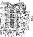
Fig. 3 is a cross-sectional view of the engine which is cut horizontally at a cylinder head part, when seen from above. -
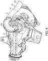
Fig. 4 is a perspective view illustrating an EGR pipe extending from a catalyst. -
Fig. 5 is a perspective view of a half-split pipe which constitutes a bend part of the EGR pipe. -
Fig. 6 is a cross-sectional view of the engine taken along a line VI-VI ofFig. 3 . -
Fig. 7 is a perspective view similar toFig. 2 , furnished with the heat insulator. - Hereinafter, an embodiment for carrying out the present disclosure is described with reference to the accompanying drawings. The following description is merely illustration, and it is not intended to limit the present disclosure, its application, or its usage. All of the features as described may not necessarily be essential.
- An
engine 1 illustrated inFig. 1 is a multi-cylinder engine which drives a vehicle (particularly an automobile), and in this example, is an inline four-cylinder four-cycle engine. Theengine 1 particularly includes acylinder block 2, acylinder head 3 which is coupled to an upper surface of thecylinder block 2, anoil pan 4 coupled to a lower surface of thecylinder block 2, and acylinder head cover 9 fixed onto thecylinder head 3. Theengine 1 is particularly mounted to a front part of the vehicle, which is a so-called "transverse engine" in which the cylinder lined-up direction is oriented substantially in a vehicle width direction. An arrow F ofFig. 1 indicates front or forward of the vehicle, and an arrow R indicates rear or rearward of the vehicle. The same will be applied to other drawings. - An intake manifold is particularly disposed forward of the
engine 1, and anexhaust manifold 5 is particularly disposed rearward of theengine 1. Intake air is introduced from the intake manifold into an intake port of each cylinder which opens to a forward side surface of thecylinder head 3. Exhaust gas which is generated inside a combustion chamber of each cylinder is discharged to theexhaust manifold 5 from an exhaust port of each cylinder which opens to a rearward side surface of thecylinder head 3. Thus, theengine 1 is particularly a front-intake rear-exhaust engine in which the front side is an intake side and the rear side is an exhaust side. - In the following description of an exhaust recirculation system, an "upstream end" means an upstream end of an exhaust gas flow or an exhaust gas recirculation (EGR) gas flow, and a "downstream end" means a downstream end of the exhaust gas flow or the EGR gas flow.
- The
exhaust manifold 5 is particularly provided with afirst collecting pipe 6, asecond collecting pipe 7, and athird collecting pipe 8. Thefirst collecting pipe 6 is tubing which collectsindependent exhaust pipes engine 1. Thesecond collecting pipe 7 is tubing which collectsindependent exhaust pipes engine 1. Thethird collecting pipe 8 is tubing which collects thefirst collecting pipe 6 and thesecond collecting pipe 7. That is, theexhaust manifold 5 is particularly a 4-2-1 type manifold. - As for the
engine 1, the exhaust order of the four cylinders is particularly defined so that exhaust timings of the two center cylinders do not overlap with each other and exhaust timings of the two end cylinders do not overlap with each other. In detail, if the cylinder at the left end is called a first cylinder and other cylinders lined up to the right side are called a second cylinder, a third cylinder, and a fourth cylinder, respectively, exhaust gas flows in the order of the first cylinder, the third cylinder, the fourth cylinder, and the second cylinder. Exhaust interference is suppressed by increasing the distance from the exhaust port of each cylinder to the collected location of thefirst collecting pipe 6 and thesecond collecting pipe 7 to thethird collecting pipe 8. - As also illustrated in
Fig. 2 , the independent exhaust pipes 11-14 particularly extend rearwardly from the rearward side surface of thecylinder head 3. Theindependent exhaust pipes independent exhaust pipes independent exhaust pipes first collecting pipe 6 which collects the centerindependent exhaust pipes second collecting pipe 7. Thefirst collecting pipe 6 and thesecond collecting pipe 7 particularly extend rearwardly so that thefirst pipe 6 is located above thesecond pipe 7, and are then bent while descending obliquely so that they extend toward one side of the vehicle width direction (the cylinder lined-up direction) and return toward thecylinder block 2, and are then collected and connected to thethird collecting pipe 8. Thethird collecting pipe 8 extends toward thecylinder block 2. - A
catalyst 15 which purifies exhaust gas of theengine 1 is connected to a downstream end of the third collecting pipe 8 (i.e., a downstream end of the exhaust manifold 5). Thecatalyst 15 particularly accommodates in a cylindrical case a honeycomb catalyst in which a honeycomb carrier supports a catalyst component. Thecatalyst 15 particularly extends, below thefirst collecting pipe 6 and thesecond collecting pipe 7, toward one side in the cylinder lined-up direction along a rearward side surface of thecylinder block 2. In other words, thecatalyst 15 is disposed so that the catalyst center axis is substantially oriented in the cylinder lined-up direction or in a direction close to the cylinder lined-up direction so that exhaust gas flows inside the catalyst from a first side (or a left side) to a second side (or a right side) in the cylinder lined-up direction of theengine 1. - The
third collecting pipe 8 is particularly connected to an upstream end of the cylindrical case of thecatalyst 15, and a downstream end of the case is particularly connected to an exhaustgas outlet pipe 16 extending rearwardly. The exhaustgas outlet pipe 16 is particularly connected to anexhaust pipe 18 extending rearwardly, via aflexible tube 17. - An
EGR gas outlet 21, which takes out part of the exhaust gas which has passed thecatalyst 15 as EGR gas and is recirculated to the intake side of theengine 1, is particularly provided at an upstream end of the exhaustgas outlet pipe 16 connected to the case of thecatalyst 15. TheEGR gas outlet 21 is located on the second side in the cylinder lined-up direction of theengine 1 with respect to the center in the cylinder lined-up direction (a flowing-out direction of the exhaust gas from the catalyst 15), and opens toward this side. - As illustrated in
Fig. 3 , an in-head EGR passage 22 which penetrates thecylinder head 3 is particularly formed in thecylinder head 3 so that the EGR gas passes through the in-head EGR passage 22. The in-head EGR passage 22 is a passage for sending EGR gas from the exhaust side to the intake side of theengine 1, and itsinlet 23 particularly opens in an exhaust-side side surface of thecylinder head 3, at an end of thecylinder head 3 on the first side in the cylinder lined-up direction (first cylinder side). - Thus, a
first EGR pipe 24, which leads EGR gas from theEGR gas outlet 21 to the in-head EGR passage 22, extends from theEGR gas outlet 21 to the first side in the cylinder lined-up direction, and is directly connected to theinlet 23 of the in-head EGR passage 22. That is, an EGR cooler is not provided to thefirst EGR pipe 24 which extends from theEGR gas outlet 21 to theinlet 23 of the in-head EGR passage 22. As it will be described later, as illustrated inFig. 1 etc., anEGR cooler 25 is not disposed on the exhaust side of theengine 1, but is disposed on the intake side of theengine 1. - As described previously, the
EGR gas outlet 21 particularly opens toward the second side in the cylinder lined-up direction. Therefore, as illustrated inFig. 4 , thefirst EGR pipe 24 is provided with aU-shaped bend 24a which changes the flow direction of EGR gas so that the EGR gas which flows out of theEGR gas outlet 21 toward the second side goes to the first side in the cylinder lined-up direction where theinlet 23 of the in-head EGR passage 22 exists. - Describing concretely, the
first EGR pipe 24 is particularly comprised of theupstream bend 24a connected at one end to theEGR gas outlet 21, and adownstream part 24b which continues from the other end of thebend 24a and extends to theinlet 23 of the in-head EGR passage 22. Thedownstream part 24b particularly extends to the first side in the cylinder lined-up direction while passing through below theexhaust manifold 5 between thecylinder head 3 and thecatalyst 15, is bent forward at a position corresponding to the one end of theengine 1 in the cylinder lined-up direction, and is connected at a tip end to theinlet 23 of the in-head EGR passage 22. - The
bend 24a is particularly formed by uniting a pair of half-split pipes into a complete pipe. As one of the half-split pipe (24al) of thebend 24a is illustrated inFig. 5 , an inner diameter D1 of the curved part of thebend 24a is particularly larger than an inner diameter D2 of the connecting part to thedownstream part 24b. That is, thefirst EGR pipe 24 particularly has a larger passage cross-sectional area at the curved part of thebend 24a than at thedownstream part 24b. - As illustrated in
Fig. 3 , the in-head EGR passage 22 particularly extends from theinlet 23 which opens in the exhaust-side side surface of thecylinder head 3, toward the intake side of theengine 1 at one end in the cylinder lined-up direction of thecylinder head 3. The in-head EGR passage 22 is particularly bent to the first side in the cylinder lined-up direction at a position just before the intake-side side surface of thecylinder head 3, and anoutlet 26 opens in one end surface of thecylinder head 3 in the cylinder lined-up direction. - A
pump mounting plate 28 which supports afuel pump 27 to thecylinder head 3 is particularly fixed to the one end surface of thecylinder head 3. AnEGR passage 29 where EGR gas flows in from theoutlet 26 of the in-head EGR passage 22 is particularly formed in thepump mounting plate 28. - As illustrated in
Fig. 6 , theEGR passage 29 particularly extends upwardly, and an upstream end of asecond EGR pipe 31 is particularly connected to theEGR passage 29. As illustrated inFig. 2 , thesecond EGR pipe 31 particularly extends to the intake side of theengine 1, and a downstream end thereof is particularly connected at the intake side to an inlet of theEGR cooler 25 of which the longitudinal direction extends in the cylinder lined-up direction (or a direction close to the cylinder lined-up direction). As for theEGR cooler 25, one end in the cylinder lined-up direction becomes an inlet of EGR gas and the other end becomes an outlet. Thesecond EGR pipe 31 is particularly covered with aprotector 32. - An upstream end of a
third EGR pipe 33 is connected to the outlet of theEGR cooler 25. The downstream end of thethird EGR pipe 33 is connected to anEGR valve 34 which adjusts an EGR gas flow rate to a surge tank of the intake manifold. - As illustrated in
Fig. 7 , a heat insulator (exhaust insulator) 35 which covers theexhaust manifold 5 and thecatalyst 15 is particularly provided on the exhaust side of theengine 1. Theheat insulator 35 is particularly formed by uniting an upper insulator which covers theexhaust manifold 5 and thecatalyst 15 from above, and a lower insulator which covers them from below. Thefirst EGR pipe 24 is disposed inside theheat insulator 35. As illustrated inFigs. 1 to 3 , awater pump 36 is particularly provided to the other end of theengine 1 in the cylinder lined-up direction. Acoolant pipe 37 which sends engine coolant from thewater pump 36 to thefuel pump 27 also passes through the inside of theheat insulator 35. Thefirst EGR pipe 24 and thecoolant pipe 37 particularly intersect with each other while being close to each other inside theheat insulator 35. - According to the
engine 1, by disposing thecatalyst 15 on the exhaust side so that exhaust gas flows from a first side toward a second side in the cylinder lined-up direction, theEGR gas outlet 21 is disposed on the second side with respect to the center of theengine 1 in the cylinder lined-up direction. On the other hand, theinlet 23 of the in-head EGR passage 22 is arranged at one end of thecylinder head 3 in the cylinder lined-up direction. Thus, thefirst EGR pipe 24 extending from theEGR gas outlet 21 is directly connected to theinlet 23 of the in-head EGR passage 22, without having the interveningEGR cooler 25. - Therefore, the
first EGR pipe 24 has a longer pipe length extending from theEGR gas outlet 21 than the case where it is connected to theEGR cooler 25, and it becomes further longer by being provided with thebend 24a. Therefore, even if hot exhaust gas is introduced from theEGR gas outlet 21 into thefirst EGR pipe 24, a heat release amount in the middle of thefirst EGR pipe 24 reaching to theinlet 23 of the in-head EGR passage 22 becomes larger. In addition, in this embodiment, since a flow velocity of EGR gas becomes slower in thebend 24a where the passage cross-sectional area is large, heat is easy to be radiated from thefirst EGR pipe 24. - Therefore, an elongation of the
first EGR pipe 24 due to the heat of exhaust gas is suppressed, and a great increase in the temperature near theinlet 23 of the in-head EGR passage 22 is also avoided. For this reason, large heat stress at the connecting part of thefirst EGR pipe 24 to the in-head EGR passage 22 will not be produced, and thermal fatigue of the connecting part is suppressed. In addition, since thecylinder head 3 intervenes between thefirst EGR pipe 24 and theEGR cooler 25, vibration of theEGR cooler 25 will not directly propagate to the connecting part of thefirst EGR pipe 24. Therefore, an early-stage damage of thefirst EGR pipe 24 at the connecting part will not be caused, and the durability improves. - According to this embodiment, by covering the
exhaust manifold 5 and thecatalyst 15 with theheat insulator 35, it is advantageous to promptly raise the temperature of thecatalyst 15 to activate thecatalyst 15 at a cold start of theengine 1 and to prevent a fall of the catalyst temperature (catalytic activity) in a cold climate. Thus, by disposing thefirst EGR pipe 24 inside theheat insulator 35, EGR gas which stagnates in thefirst EGR pipe 24 is prevented from being rapidly cooled by low-temperature open air when theengine 1 is stopped. Therefore, even when thefirst EGR pipe 24 is long and there is a lot of stagnated EGR gas, moisture contained in the EGR gas condensing is suppressed. - Further, in this embodiment, since the 4-2-1
type exhaust manifold 5 is adopted, exhaust interference is suppressed and exhaust gas becomes more easily discharged from each cylinder. Therefore, it is advantageous to stabilize and optimize the exhaust gas recirculation. - Note that in this embodiment, although the 4-2-1
type exhaust manifold 5 is adopted, the exhaust manifold may be a 4-1 type. - Further, the
engine 1 may not only be the four-cylinder engine but may be a six-cylinder engine, or may be a longitudinal engine in which the cylinder lined-up direction is oriented in a vehicle front-and-rear direction. - It should be understood that the embodiments herein are illustrative and not restrictive, since the scope of the invention is defined by the appended claims rather than by the description preceding them.
-
- 1
- Engine
- 2
- Cylinder Block
- 3
- Cylinder Head
- 5
- Exhaust Manifold
- 6
- First Collecting Pipe
- 7
- Second Collecting Pipe
- 8
- Third Collecting Pipe
- 9
- Cylinder Head Cover
- 11-14
- Independent Exhaust Pipe
- 15
- Catalyst
- 16
- Exhaust Gas Outlet Pipe
- 21
- EGR Gas Outlet
- 22
- In-head EGR Passage
- 23
- Inlet of In-head EGR Passage
- 24
- First EGR Pipe
- 24a
- Bend
- 24b
- Downstream Part
- 25
- EGR Cooler
- 35
- Heat Insulator
Claims (15)
- An exhaust gas recirculation system for a multi-cylinder engine (1), comprising:an exhaust manifold (5) connected to a cylinder head (3) of the engine (1) and configured to collect exhaust gas discharged from each cylinder of the engine (1);a catalyst (15) connected to a downstream end of the exhaust manifold (5) with respect to an exhaust gas flow and configured to purify the exhaust gas;an EGR gas outlet (21) provided downstream of the catalyst (15) and configured to take out part of the exhaust gas as EGR gas to be recirculated to an intake side of the engine (1);an in-head EGR passage (22) penetrating the cylinder head (3) and through which the EGR gas passes; andan EGR pipe (24) extending from the EGR gas outlet (21) and configured to lead the EGR gas to the in-head EGR passage (22),wherein the catalyst (15) is disposed so that the exhaust gas flows inside the catalyst (15) from a first side to a second side in a cylinder lined-up direction of the engine (1),wherein the EGR gas outlet (21) is located on the second side with respect to the center of the engine (1) in the cylinder lined-up direction,wherein an inlet (23) of the in-head EGR passage (22) is located in the first side with respect to the center of the engine (1) in the cylinder lined-up direction, andwherein the EGR pipe (24) extending from the EGR gas outlet (21) is directly connected to the inlet (23) of the in-head EGR passage (22).
- The exhaust gas recirculation system of claim 1,wherein the EGR gas outlet (21) opens toward the second side in the cylinder lined-up direction, andwherein the EGR pipe (24) has a bend (24a) configured to change a flow direction of the EGR gas so that the EGR gas flowing from the EGR gas outlet (21) to the second side flows to the first side in the cylinder lined-up direction where the inlet (23) of the in-head EGR passage (22) exists.
- The exhaust gas recirculation system of claim 2, wherein the EGR pipe (24) has a larger passage cross-sectional area at the bend (24a) than at a downstream part (24b) extending continuously from the bend (24a) to the inlet (23) of the in-head EGR passage (22).
- The exhaust gas recirculation system of any one of the preceding claims, further comprising a heat insulator (35) covering the exhaust manifold (5) and the catalyst (15),
wherein the EGR pipe (24) is disposed inside the heat insulator (35). - The exhaust gas recirculation system of any one of the preceding claims,wherein the engine (1) is an inline four-cylinder four-cycle engine,wherein the exhaust manifold (5) is provided with a first collecting pipe (6) where independent exhaust pipes leading to two center cylinders in the cylinder lined-up direction of the engine (1) are collected, a second collecting pipe (7) where independent exhaust pipes leading to two end cylinders in the cylinder lined-up direction of the engine (1) are collected, and a third collecting pipe (8) where the first collecting pipe (6) and the second collecting pipe (7) are collected,wherein the engine (1) is configured with an exhaust order of the four cylinders so that exhaust timings of the two center cylinders do not overlap with each other and exhaust timings of the two end cylinders do not overlap with each other, andwherein the catalyst (15) is connected to the third collecting pipe (8).
- The exhaust gas recirculation system of any one of the preceding claims,
wherein the exhaust manifold (5) is a 4-2-1 type. - The exhaust gas recirculation system of any one of the preceding claims, further comprising an EGR cooler (25) configured to cool the EGR gas,
wherein the EGR cooler (25) is disposed in the engine (1) on the intake side opposite to an exhaust side where the exhaust manifold (5) is disposed, and the EGR gas that passes through the in-head EGR passage (22) is then introduced into the EGR cooler (25). - The exhaust gas recirculation system of claim 7,
wherein the EGR pipe (24) is connected to the inlet (23) without intervening the EGR cooler (25). - The exhaust gas recirculation system of claim 7 or 8, further comprising a pump mounting plate (28) which supports a fuel pump (27),
wherein a passage (29) where the EGR gas flows in from an outlet (26) of the in-head EGR passage (22) is formed in the pump mounting plate (28). - The exhaust gas recirculation system of claim 9, further comprising a pipe (31) extending between the passage (29) and the EGR cooler (25), at least partially in the cylinder lined-up direction.
- The exhaust gas recirculation system of any one of the preceding claims, wherein
the inlet (23) opens in an side surface of the cylinder head (3). - A multi-cylinder engine (1) comprising the exhaust gas recirculation system of any one of the preceding claims.
- A vehicle comprising the multi-cylinder engine (1) of claim 12.
- The vehicle of claim 13,
wherein the cylinder lined-up direction substantially corresponds to a vehicle width direction. - The vehicle of claim 13 or 14.
wherein the first side is a left side, and the second side is a right side.
Applications Claiming Priority (1)
| Application Number | Priority Date | Filing Date | Title |
|---|---|---|---|
| JP2020180182A JP7400693B2 (en) | 2020-10-28 | 2020-10-28 | Engine exhaust circulation system |
Publications (1)
| Publication Number | Publication Date |
|---|---|
| EP3992448A1 true EP3992448A1 (en) | 2022-05-04 |
Family
ID=78371941
Family Applications (1)
| Application Number | Title | Priority Date | Filing Date |
|---|---|---|---|
| EP21204164.4A Withdrawn EP3992448A1 (en) | 2020-10-28 | 2021-10-22 | Engine exhaust gas recirculation system, multi-cylinder engine, and vehicle |
Country Status (3)
| Country | Link |
|---|---|
| US (1) | US11499509B2 (en) |
| EP (1) | EP3992448A1 (en) |
| JP (1) | JP7400693B2 (en) |
Cited By (1)
| Publication number | Priority date | Publication date | Assignee | Title |
|---|---|---|---|---|
| EP4656865A1 (en) * | 2024-05-30 | 2025-12-03 | Toyota Jidosha Kabushiki Kaisha | Internal combustion engine |
Families Citing this family (1)
| Publication number | Priority date | Publication date | Assignee | Title |
|---|---|---|---|---|
| CN115788659A (en) * | 2022-11-30 | 2023-03-14 | 重庆长安汽车股份有限公司 | A heat shield assembly at the exhaust hot end of a supercharged model |
Citations (5)
| Publication number | Priority date | Publication date | Assignee | Title |
|---|---|---|---|---|
| EP1387052A1 (en) * | 2002-07-30 | 2004-02-04 | Nissan Motor Company, Limited | Engine exhaust apparatus |
| JP2010270710A (en) * | 2009-05-22 | 2010-12-02 | Mitsubishi Motors Corp | Exhaust system structure of internal combustion engine |
| DE102014211677A1 (en) * | 2013-06-27 | 2014-12-31 | Suzuki Motor Corporation | EXHAUST GAS RECYCLING SYSTEM FOR MOTOR VEHICLE ENGINES |
| JP2015124692A (en) | 2013-12-26 | 2015-07-06 | ダイハツ工業株式会社 | Internal combustion engine |
| EP3889417A1 (en) * | 2020-04-01 | 2021-10-06 | Mazda Motor Corporation | Egr system of engine, engine comprising egr system and automobile |
Family Cites Families (8)
| Publication number | Priority date | Publication date | Assignee | Title |
|---|---|---|---|---|
| JPH06101462A (en) * | 1992-09-21 | 1994-04-12 | Yamaha Motor Co Ltd | Exhaust device for internal combustion engine for vehicles |
| JP4297067B2 (en) * | 2005-03-15 | 2009-07-15 | トヨタ自動車株式会社 | Exhaust gas recirculation device |
| JP2011236849A (en) * | 2010-05-12 | 2011-11-24 | Toyota Motor Corp | Exhaust cooling system of internal combustion engine and exhaust cooling adapter |
| WO2012056885A1 (en) * | 2010-10-28 | 2012-05-03 | 本田技研工業株式会社 | Egr cooler structure |
| WO2013054711A1 (en) * | 2011-10-12 | 2013-04-18 | 本田技研工業株式会社 | Exhaust gas recirculation device for internal combustion engine |
| JP2015140711A (en) * | 2014-01-28 | 2015-08-03 | トヨタ自動車株式会社 | exhaust manifold |
| JP6308053B2 (en) * | 2014-07-02 | 2018-04-11 | スズキ株式会社 | Exhaust gas recirculation device for internal combustion engine |
| JP7024639B2 (en) * | 2018-07-17 | 2022-02-24 | トヨタ自動車株式会社 | Exhaust structure of internal combustion engine |
-
2020
- 2020-10-28 JP JP2020180182A patent/JP7400693B2/en active Active
-
2021
- 2021-10-20 US US17/451,600 patent/US11499509B2/en active Active
- 2021-10-22 EP EP21204164.4A patent/EP3992448A1/en not_active Withdrawn
Patent Citations (5)
| Publication number | Priority date | Publication date | Assignee | Title |
|---|---|---|---|---|
| EP1387052A1 (en) * | 2002-07-30 | 2004-02-04 | Nissan Motor Company, Limited | Engine exhaust apparatus |
| JP2010270710A (en) * | 2009-05-22 | 2010-12-02 | Mitsubishi Motors Corp | Exhaust system structure of internal combustion engine |
| DE102014211677A1 (en) * | 2013-06-27 | 2014-12-31 | Suzuki Motor Corporation | EXHAUST GAS RECYCLING SYSTEM FOR MOTOR VEHICLE ENGINES |
| JP2015124692A (en) | 2013-12-26 | 2015-07-06 | ダイハツ工業株式会社 | Internal combustion engine |
| EP3889417A1 (en) * | 2020-04-01 | 2021-10-06 | Mazda Motor Corporation | Egr system of engine, engine comprising egr system and automobile |
Cited By (1)
| Publication number | Priority date | Publication date | Assignee | Title |
|---|---|---|---|---|
| EP4656865A1 (en) * | 2024-05-30 | 2025-12-03 | Toyota Jidosha Kabushiki Kaisha | Internal combustion engine |
Also Published As
| Publication number | Publication date |
|---|---|
| US20220128019A1 (en) | 2022-04-28 |
| US11499509B2 (en) | 2022-11-15 |
| JP7400693B2 (en) | 2023-12-19 |
| JP2022071297A (en) | 2022-05-16 |
Similar Documents
| Publication | Publication Date | Title |
|---|---|---|
| JP5805206B2 (en) | Exhaust gas recirculation device for internal combustion engine | |
| US7704111B2 (en) | Exhaust system of outboard motor | |
| US7841323B2 (en) | Internal-combustion engine having a cooled exhaust gas recirculation system as well as an exhaust gas manifold | |
| CN104411957A (en) | Exhaust passage structure for internal combustion engine | |
| US11499509B2 (en) | Engine exhaust gas recirculation system | |
| CN107559073B (en) | Exhaust Control Systems for Internal Combustion Engines | |
| JP2011038467A (en) | Exhaust gas recirculating device of engine | |
| US10233805B2 (en) | Exhaust gas control system | |
| EP3816418A1 (en) | Exhaust system for engine, engine and vehicle | |
| US20120006019A1 (en) | Internal combustion engine with horizontally arranged cylinder banks and exhaust-gas turbocharger | |
| CN116085102A (en) | Engine with a motor | |
| JP6296789B2 (en) | Internal combustion engine | |
| CN113494394A (en) | EGR system of engine | |
| JP2009150243A (en) | Turbocharged engine | |
| JP4591270B2 (en) | Exhaust device for internal combustion engine | |
| EP3517769B1 (en) | Engine intake and exhaust system and internal combustion engine | |
| KR0169410B1 (en) | Exhaust system of a v-engine | |
| CN219587668U (en) | Engine with overhead EGR cooling system | |
| JP7275873B2 (en) | vehicle front structure | |
| JP3856207B2 (en) | Exhaust device for multi-cylinder internal combustion engine | |
| KR102773423B1 (en) | Heat recovery device using vehicle exhaust gas | |
| JP7293882B2 (en) | engine exhaust structure | |
| US20140352938A1 (en) | Egr cooler header design | |
| JP7196755B2 (en) | vehicle engine | |
| JP2018141412A (en) | Exhaust device for internal combustion engine |
Legal Events
| Date | Code | Title | Description |
|---|---|---|---|
| PUAI | Public reference made under article 153(3) epc to a published international application that has entered the european phase |
Free format text: ORIGINAL CODE: 0009012 |
|
| STAA | Information on the status of an ep patent application or granted ep patent |
Free format text: STATUS: THE APPLICATION HAS BEEN PUBLISHED |
|
| AK | Designated contracting states |
Kind code of ref document: A1 Designated state(s): AL AT BE BG CH CY CZ DE DK EE ES FI FR GB GR HR HU IE IS IT LI LT LU LV MC MK MT NL NO PL PT RO RS SE SI SK SM TR |
|
| STAA | Information on the status of an ep patent application or granted ep patent |
Free format text: STATUS: THE APPLICATION IS DEEMED TO BE WITHDRAWN |
|
| 18D | Application deemed to be withdrawn |
Effective date: 20221105 |