EP3992435A1 - Turbine casing for gas turbine engine - Google Patents
Turbine casing for gas turbine engine Download PDFInfo
- Publication number
- EP3992435A1 EP3992435A1 EP21206045.3A EP21206045A EP3992435A1 EP 3992435 A1 EP3992435 A1 EP 3992435A1 EP 21206045 A EP21206045 A EP 21206045A EP 3992435 A1 EP3992435 A1 EP 3992435A1
- Authority
- EP
- European Patent Office
- Prior art keywords
- flange
- tsc
- exhaust case
- case
- radially
- Prior art date
- Legal status (The legal status is an assumption and is not a legal conclusion. Google has not performed a legal analysis and makes no representation as to the accuracy of the status listed.)
- Granted
Links
Images

Classifications
-
- F—MECHANICAL ENGINEERING; LIGHTING; HEATING; WEAPONS; BLASTING
- F01—MACHINES OR ENGINES IN GENERAL; ENGINE PLANTS IN GENERAL; STEAM ENGINES
- F01D—NON-POSITIVE DISPLACEMENT MACHINES OR ENGINES, e.g. STEAM TURBINES
- F01D25/00—Component parts, details, or accessories, not provided for in, or of interest apart from, other groups
- F01D25/24—Casings; Casing parts, e.g. diaphragms, casing fastenings
- F01D25/243—Flange connections; Bolting arrangements
-
- F—MECHANICAL ENGINEERING; LIGHTING; HEATING; WEAPONS; BLASTING
- F01—MACHINES OR ENGINES IN GENERAL; ENGINE PLANTS IN GENERAL; STEAM ENGINES
- F01D—NON-POSITIVE DISPLACEMENT MACHINES OR ENGINES, e.g. STEAM TURBINES
- F01D25/00—Component parts, details, or accessories, not provided for in, or of interest apart from, other groups
- F01D25/16—Arrangement of bearings; Supporting or mounting bearings in casings
- F01D25/162—Bearing supports
-
- F—MECHANICAL ENGINEERING; LIGHTING; HEATING; WEAPONS; BLASTING
- F01—MACHINES OR ENGINES IN GENERAL; ENGINE PLANTS IN GENERAL; STEAM ENGINES
- F01D—NON-POSITIVE DISPLACEMENT MACHINES OR ENGINES, e.g. STEAM TURBINES
- F01D25/00—Component parts, details, or accessories, not provided for in, or of interest apart from, other groups
- F01D25/30—Exhaust heads, chambers, or the like
-
- F—MECHANICAL ENGINEERING; LIGHTING; HEATING; WEAPONS; BLASTING
- F01—MACHINES OR ENGINES IN GENERAL; ENGINE PLANTS IN GENERAL; STEAM ENGINES
- F01D—NON-POSITIVE DISPLACEMENT MACHINES OR ENGINES, e.g. STEAM TURBINES
- F01D9/00—Stators
- F01D9/06—Fluid supply conduits to nozzles or the like
- F01D9/065—Fluid supply or removal conduits traversing the working fluid flow, e.g. for lubrication-, cooling-, or sealing fluids
-
- F—MECHANICAL ENGINEERING; LIGHTING; HEATING; WEAPONS; BLASTING
- F05—INDEXING SCHEMES RELATING TO ENGINES OR PUMPS IN VARIOUS SUBCLASSES OF CLASSES F01-F04
- F05D—INDEXING SCHEME FOR ASPECTS RELATING TO NON-POSITIVE-DISPLACEMENT MACHINES OR ENGINES, GAS-TURBINES OR JET-PROPULSION PLANTS
- F05D2230/00—Manufacture
- F05D2230/20—Manufacture essentially without removing material
- F05D2230/21—Manufacture essentially without removing material by casting
-
- F—MECHANICAL ENGINEERING; LIGHTING; HEATING; WEAPONS; BLASTING
- F05—INDEXING SCHEMES RELATING TO ENGINES OR PUMPS IN VARIOUS SUBCLASSES OF CLASSES F01-F04
- F05D—INDEXING SCHEME FOR ASPECTS RELATING TO NON-POSITIVE-DISPLACEMENT MACHINES OR ENGINES, GAS-TURBINES OR JET-PROPULSION PLANTS
- F05D2230/00—Manufacture
- F05D2230/20—Manufacture essentially without removing material
- F05D2230/25—Manufacture essentially without removing material by forging
-
- F—MECHANICAL ENGINEERING; LIGHTING; HEATING; WEAPONS; BLASTING
- F05—INDEXING SCHEMES RELATING TO ENGINES OR PUMPS IN VARIOUS SUBCLASSES OF CLASSES F01-F04
- F05D—INDEXING SCHEME FOR ASPECTS RELATING TO NON-POSITIVE-DISPLACEMENT MACHINES OR ENGINES, GAS-TURBINES OR JET-PROPULSION PLANTS
- F05D2230/00—Manufacture
- F05D2230/60—Assembly methods
-
- F—MECHANICAL ENGINEERING; LIGHTING; HEATING; WEAPONS; BLASTING
- F05—INDEXING SCHEMES RELATING TO ENGINES OR PUMPS IN VARIOUS SUBCLASSES OF CLASSES F01-F04
- F05D—INDEXING SCHEME FOR ASPECTS RELATING TO NON-POSITIVE-DISPLACEMENT MACHINES OR ENGINES, GAS-TURBINES OR JET-PROPULSION PLANTS
- F05D2240/00—Components
- F05D2240/10—Stators
- F05D2240/14—Casings or housings protecting or supporting assemblies within
-
- F—MECHANICAL ENGINEERING; LIGHTING; HEATING; WEAPONS; BLASTING
- F05—INDEXING SCHEMES RELATING TO ENGINES OR PUMPS IN VARIOUS SUBCLASSES OF CLASSES F01-F04
- F05D—INDEXING SCHEME FOR ASPECTS RELATING TO NON-POSITIVE-DISPLACEMENT MACHINES OR ENGINES, GAS-TURBINES OR JET-PROPULSION PLANTS
- F05D2260/00—Function
- F05D2260/30—Retaining components in desired mutual position
- F05D2260/31—Retaining bolts or nuts
Definitions
- a method of assembling a turbine casing of a gas turbine engine comprising: abutting a flange of a turbine support case (TSC) against a flange of an exhaust case to abut part of the flange of the TSC against an outer diameter surface of the flange of the exhaust case, and to position leading edge portions of struts of the exhaust case at positions along a center axis being similar to a position of the flange of the exhaust case along the center axis; and securing the flanges of the TSC and the exhaust case together to assemble the TSC with the exhaust case, the assembled TSC and exhaust case configured to displace together with a resiliently deformable portion of the TSC adjacent to the flange of the TSC.
- TSC turbine support case
- the casing of the gas turbine engine 10 includes a turbine casing assembly 19 which is part of the hot section 12B.
- the turbine casing assembly 19 is a group of casing components that form part of the turbine section 18 and enclose the combustion gases.
- the turbine casing assembly 19 may be provided as disassembled cases which may then be assembled in a suitable facility.
- the turbine casing assembly 19 includes a first case 20 and a second case 30.
- the first case 20 is a turbine support case (TSC) and is thus sometimes referred to herein as “turbine support case 20" or "TSC 20".
- TSC turbine support case
- the TSC and exhaust case flanges 24, 34 are mating and secured together such that the TSC 20 and the exhaust case 30 are assembled together, some or all of the TSC flange 24 abuts against the radially-outer wall 34A of the exhaust case flange 34, and against other portions of the exhaust case flange 34 as well.
- the TSC flange 24 radially overlaps the exhaust case flange 34 at its outer diameter ⁇ .
- the TSC and exhaust case flanges 24, 34 thus form a flange/joint arrangement that includes an interface along the outer diameter ⁇ of the exhaust case flange 34.
- This tight fit at the outer diameter ⁇ helps to maintain the mating faces of the TSC and exhaust case flanges 24, 34 in abutment through the application of compressive forces on the mating faces during thermal expansion of part of the exhaust case 30, as described in greater detail below, through all engine running conditions.
- the method includes abutting the TSC flange 24 against the exhaust case flange 34 to abut part of the TSC flange 24 against the outer diameter surface of the exhaust case flange 34.
- This also includes positioning leading edge portions 38A of the struts 36 at positions along the center axis 11 that are similar to a position of the exhaust case flange 34 along the center axis 11.
- the method includes securing the flanges 24, 34 together to assemble the TSC 20 with the exhaust case 30.
- the assembled TSC and exhaust case 20, 30 are configured to displace together with a resiliently deformable portion 23 of the TSC 20 adjacent to the TSC flange 24.
Landscapes
- Engineering & Computer Science (AREA)
- Mechanical Engineering (AREA)
- General Engineering & Computer Science (AREA)
- Physics & Mathematics (AREA)
- Fluid Mechanics (AREA)
- Exhaust Silencers (AREA)
- Turbine Rotor Nozzle Sealing (AREA)
Abstract
Description
- The application relates generally to gas turbine engines and, more particularly, to turbine casing arrangements for such engines.
- During operation of gas turbine engines, parts of the engine are exposed to the hot combustion gases. During transient events, such as when the gas turbine engine is started, the temperature of these parts may rapidly increase from a relative cold temperature to the hot temperature of the combustion gases.
- The rapid increase in temperature of the parts exposed to the hot combustion gases may cause them to undergo thermal expansion. If these parts are mounted to other components which do not experience such a rapid increase in temperature, a thermal mismatch may result and may lead to thermally-induced stresses.
- According to an aspect of the present invention there is a turbine casing assembly, comprising: a turbine support case (TSC) having a TSC body defined about a center axis with a TSC flange, the TSC body (immediately) adjacent to (and/or directly connected to and/or contiguous with) the TSC flange being resiliently deformable; and an exhaust case having an exhaust case body defined about the center axis with an exhaust case flange extending radially outwardly from the exhaust case body to a radially-outer wall defining an outer diameter of the exhaust case flange, the exhaust case flange configured to be secured to the TSC flange to abut the TSC flange against the radially-outer wall of the exhaust case flange and attach the TSC to the exhaust case, the exhaust case having struts circumferentially spaced apart about the center axis, each of the struts extending radially from an inner end to an outer end attached to the exhaust case body, each of the struts extending between a leading edge portion and a trailing edge portion, the leading edge portion at the outer end of each of the struts having an axial position defined along the center axis that is similar to an axial position of the exhaust case flange.
- According to another aspect of the present invention there is a gas turbine engine, comprising: a hot section of the gas turbine engine having a rotor with rotor blades rotatable about a center axis of the gas turbine engine; a first case with a first case body defined about the center axis and at least partially disposed in the hot section, the first case body having a first case flange and the first case body adjacent to the first case flange being resiliently deformable; and a second case downstream of the first case and having a second case body defined about the center axis with a second case flange extending radially outwardly from the second case body to a radially-outer wall defining an outer diameter of the second case flange, the second case flange secured to the first case flange and the first case flange abutting the radially-outer wall of the second case flange, the second case having struts circumferentially spaced apart about the center axis, each of the struts extending radially from an inner end to an outer end attached to the second case body, each of the struts extending between a leading edge portion and a trailing edge portion, the leading edge portion at the outer end of each of the struts having an axial position defined along the center axis similar to an axial position of the second case flange.
- In an embodiment of the foregoing, the first case flange may include a first portion extending radially outwardly from the first case body and a second portion extending axially from the first portion, and the second portion may abut against the radially-outer wall of the second case flange.
- In a further embodiment of any of the foregoing, the second case flange may include a plurality of holes extending through the second case flange and disposed circumferentially about the center axis, a portion of the second case flange may be circumferentially aligned with one of the struts, and the portion of the second case flange may be free of any of the plurality of holes.
- In a further embodiment of any of the foregoing, the first case flange may have a first case flange radially-outer wall, a radial thickness of the first case flange may be defined from the first case body to the first case flange radially-outer wall, the first case flange may include reinforced portions being circumferentially aligned with one of the struts, the first case flange may include other portions each disposed circumferentially between adjacent reinforced portions of the first case flange, and the radial thickness of the reinforced portions may be greater than the radial thickness of the other portions.
- In a further embodiment of any of the foregoing, the leading edge portion of each of the struts may have an outer portion at the outer end of the strut and an inner portion extending radially inwardly from the outer portion, an axial thickness of the leading edge portion may be defined along the center axis between a leading edge of the leading edge portion and an inner wall of the leading edge portion delimiting a cavity of the strut, and the axial thickness of the leading edge portion may be greatest at the outer portion.
- In a further embodiment of any of the foregoing, the first case body adjacent to the first case flange may have a first radial thickness defined between radially inner and outer surfaces of the first case body, and a remainder of the first case body may have a second radial thickness that is greater than the first radial thickness.
- According to another aspect of the present invention there is a method of assembling a turbine casing of a gas turbine engine, the method comprising: abutting a flange of a turbine support case (TSC) against a flange of an exhaust case to abut part of the flange of the TSC against an outer diameter surface of the flange of the exhaust case, and to position leading edge portions of struts of the exhaust case at positions along a center axis being similar to a position of the flange of the exhaust case along the center axis; and securing the flanges of the TSC and the exhaust case together to assemble the TSC with the exhaust case, the assembled TSC and exhaust case configured to displace together with a resiliently deformable portion of the TSC adjacent to the flange of the TSC.
- Features of embodiments are recited in the dependent claims.
- Reference is now made to the accompanying figures in which:
-
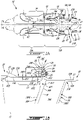
Fig. 1A is a schematic cross-sectional view of a gas turbine engine; -
Fig. 1B is an enlarged cross-sectional view of region IB-IB ofFig. 1A ; -
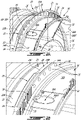
Fig. 2A is a perspective view of part of the turbine support case and exhaust case of the gas turbine engine ofFig. 1A ; -
Fig. 2B is an enlarged perspective view of region IIB-IIB ofFig. 2A ; -
Fig. 3A a schematic view of part of the exhaust case ofFig. 1A showing forces of thermal deformation; and -
Fig. 3B is an enlarged cross-sectional view ofFig. 3A showing compressive forces acting on the turbine support case and exhaust case. -
Fig. 1A illustrates agas turbine engine 10 of a type preferably provided for use in subsonic flight, generally comprising in serial flow communication acompressor section 14 for pressurizing the air, acombustor 16 in which the compressed air is mixed with fuel and ignited for generating an annular stream of hot combustion gases, and aturbine section 18 for extracting energy from the combustion gases. Some of the rotatable components of thegas turbine engine 10 rotate about alongitudinal center axis 11 of the gas turbine engine. - The
gas turbine engine 10 has a "cold"section 12A and a "hot"section 12B. Thecold section 12A includes those components of thegas turbine engine 10 which are upstream (relative to the direction gases flow through the gas turbine engine 10) of thecombustor 16 and have thus not been exposed to the hot combustion gases. Thehot section 12B includes thecombustor 16 and those components of thegas turbine engine 10 which are downstream of thecombustor 16. The components of thehot section 12B are thus exposed to the hot combustion gases generated in thecombustor 16. The gases GC flowing through thecold section 12A have a lower temperature than the gases GH flowing through thehot section 12B. - Referring to
Fig. 1A , thehot section 12B includes thecombustor 16, theturbine section 18 and a case downstream of theturbine section 18 for conveying the exhaust gases. Theturbine section 18 includes one ormore rotors 18A each havingrotor blades 18B which rotate about thecenter axis 11 and extract energy from the combustion gases. Therotors 18A androtor blades 18B of the turbine section are typically referred to as turbines and turbine blades, respectively. Thehot section 12B includes stationary bodies which enclose other components of thehot section 12B and define the gas path for the hot combustion gases. These stationary bodies are sometimes referred to as casings or cases which collectively define radially-outer boundaries of the gas turbine engine. - Referring to
Fig. 1A , the casing of thegas turbine engine 10 includes aturbine casing assembly 19 which is part of thehot section 12B. Theturbine casing assembly 19 is a group of casing components that form part of theturbine section 18 and enclose the combustion gases. Theturbine casing assembly 19 may be provided as disassembled cases which may then be assembled in a suitable facility. Theturbine casing assembly 19 includes afirst case 20 and asecond case 30. In the embodiment ofFig. 1A , thefirst case 20 is a turbine support case (TSC) and is thus sometimes referred to herein as "turbine support case 20" or "TSC 20". In the embodiment ofFig. 1A , thesecond case 30 is anexhaust case 30 for conveying the hot exhaust gases, and is mounted to theTSC 20. It will be appreciated that the first andsecond cases hot section 12B. For example, in one possible alternate configuration, thefirst case 20 houses thecombustor 16 and part of the components of thecold section 12A, and thesecond case 30 houses therotors 18A and stators of theturbine section 18. - Referring to
Fig. 1A , the TSC 20 forms part of the casing for thegas turbine engine 10. TheTSC 20 houses stationary and rotatable components of theturbine section 18 such as therotor blades 18B, disks, or stator vanes of theturbine section 18, and defines part of the gas path for the hot combustion gases through theturbine section 18. TheTSC 20 has aTSC body 22 which provides structure to theTSC 20 and forms the corpus thereof. InFig. 1A , theTSC body 22 is cylindrical about thecenter axis 11. InFig. 1A , theTSC body 22 defines part of an annular gas path for the hot combustion gases through theturbine section 18. Referring toFig. 1B , theTSC body 22 includes an inner wall 22A disposed radially inwardly (i.e. closer to the center axis 11) of anouter wall 22B. A radial thickness of theTSC body 22 is defined between the inner andouter walls 22A, 22B. - Referring to
Fig. 1B , theTSC body 22 has one ormore TSC flanges 24. TheTSC flange 24 is a radially-protruding body that is configured for mating with, and being secured to, corresponding structure of theexhaust case 30 in order to assemble theTSC 20 and theexhaust case 30. InFig. 1B , theTSC flange 24 extends radially outwardly from a radially-outermost outer surface of theTSC body 22. InFig. 1B , theTSC flange 24 extends radially outwardly from theouter wall 22B of theTSC body 22. InFigs. 1A and 1B , a radially-outermost surface of theTSC flange 24 is substantially parallel to thecenter axis 11 and defines an outer diameter of theTSC flange 24. InFigs. 1A and 1B , a radially-outermost surface of theTSC flange 24 is substantially parallel to thecenter axis 11 and defines an outer diameter of theTSC body 22. - Referring to
Fig. 1B , aportion 23 of theTSC body 22 adjacent to theTSC flange 24 is resiliently deformable. Referring toFig. 1B , theportion 23 is immediately adjacent to theTSC flange 24. Theportion 23 is immediately upstream of theTSC flange 24. Theportion 23 has an axial extent, and extends in a direction being substantially parallel to thecenter axis 11. Referring toFig. 1B , theportion 23 extends axially between anupstream extremity 23A and adownstream extremity 23B that is integral with theTSC flange 24. Theportion 23 extends axially upstream from theTSC flange 24. Theportion 23 is a cylindrical body which forms only a segment of the axial extent of theTSC body 22. - By "resiliently deformable", it is understood that the
portion 23 displaces by deforming temporarily and returns to its original shape in response to a radial displacement of parts of theexhaust case 30 due to thermal expansion, as described in greater detail below. The temporary deformation of theportion 23 is caused by the displacement ofTSC flange 24 resulting from the thermal expansion of theexhaust case 30. Theportion 23 returns to its default shape and position when thermal expansion has ceased. Theportion 23 thus acts like a hinge to accommodate temporary thermal expansion of theexhaust case 30. The resilient deformability of theportion 23 may result from its material composition, from the technique used to manufacture theportion 23, from its dimensional arrangement, and/or from any combination of the preceding factors. - Referring to
Fig. 1B , the resilient deformability of theportion 23 results at least in part from a difference in the radial thickness of theTSC body 22 adjacent to theTSC flange 24. Theportion 23 has a first radial thickness RT1 defined between the inner andouter walls 22A, 22B of theTSC body 22 along the axial extent of theportion 23. The first radial thickness RT1 is constant along the axial extent of theportion 23. A remainder of theTSC body 22, or possibly just a segment of theTSC body 22 immediately adjacent to theportion 23, has a second radial thickness RT2 that is greater than the first radial thickness RT1. Thus, inFig. 1B , the resilient deformability of theportion 23, and thus of theTSC flange 24 connected thereto, is derived at least in part from a thinner cylindrical portion of theTSC body 22 acting as a hairpin structure adjacent to theTSC flange 24 to improve the flexibility of theTSC flange 24 during thermal expansion of mating components. The resilient deformability of theportion 23 may also result from the technique used to manufacture theportion 23. For example, theportion 23 may be forged metal. Forging a metal involves shaping the metal using localized compressive forces. For example, a hammer, or another tool for applying compressive forces such as a die, may compress theportion 23 so that the grains of the metal have the properties and orientation to achieve the functionality described above. In an embodiment, theTSC body 22 is a forged metal. - Referring to
Figs. 1A and 1B , theexhaust case 30 forms part of the casing for thegas turbine engine 10. Theexhaust case 30 is disposed downstream of theTSC 20 and mounted thereto. Theexhaust case 30 houses stationary components of thehot section 12B such as anexhaust cone 31, and defines part of an annular gas path for the exhaust gases after the combustion gases have been exhausted through theturbine section 18. Theexhaust case 30 has anexhaust case body 32 which provides structure to theexhaust case 30 and forms the corpus thereof. InFig. 1A , theexhaust case body 32 is cylindrical about thecenter axis 11. Referring toFig. 1B , theexhaust case body 32 includes aninner wall 32A disposed radially inwardly (i.e. closer to the center axis 11) of anouter wall 32B. A radial thickness of theexhaust case body 32 is defined between the inner andouter walls - Referring to
Fig. 1B , theexhaust case body 32 has one or more exhaust case flanges 34. Theexhaust case flange 34 is a radially-protruding body that is configured for mating with, and being secured to, theTSC flange 24 in order to assemble theTSC 20 and theexhaust case 30. InFig. 1B , theexhaust case flange 34 extends radially outwardly from a radially-outermost outer surface of theexhaust case body 32 to a radially-outer wall 34A of theexhaust case flange 34. InFig. 1B , theexhaust case flange 34 extends radially outwardly from theouter wall 32B of theexhaust case body 32. InFigs. 1A and 1B , the radially-outer wall 34A defines a radially-outermost surface of theexhaust case flange 34 and is substantially parallel to thecenter axis 11. The radially-outer wall 34A defines the outer diameter Ø of theexhaust case flange 34. The radially-outer wall 34A defines the outer diameter Ø of theexhaust case body 32. - Referring to
Fig. 1B , when the TSC and exhaust case flanges 24, 34 are mating and secured together such that theTSC 20 and theexhaust case 30 are assembled together, some or all of theTSC flange 24 abuts against the radially-outer wall 34A of theexhaust case flange 34, and against other portions of the exhaust case flange 34 as well. TheTSC flange 24 radially overlaps the exhaust case flange 34 at its outer diameter Ø. The TSC and exhaust case flanges 24, 34 thus form a flange/joint arrangement that includes an interface along the outer diameter Ø of theexhaust case flange 34. This tight fit at the outer diameter Ø helps to maintain the mating faces of the TSC and exhaust case flanges 24, 34 in abutment through the application of compressive forces on the mating faces during thermal expansion of part of theexhaust case 30, as described in greater detail below, through all engine running conditions. - Different configurations for the mating engagement of the
TSC flange 24 with the radially-outer wall 34A of theexhaust case flange 34 are possible. For example, and referring toFig. 1B , theTSC flange 24 includes afirst portion 24A extending radially outwardly from theouter wall 22B of theTSC body 20. Thefirst portion 24A extends along a line being radial to thecenter axis 11. A radially-overlappingsecond portion 24B of theTSC flange 24 extends axially away from, and downstream of, thefirst portion 24A. Thesecond portion 24B abuts against the radially-outer wall 34A of theexhaust case flange 34. A radially-innermost wall of thesecond portion 24B abuts against the radially-outer wall 34A of theexhaust case flange 34. Thesecond portion 24B abuts against the radially-outer wall 34A of the exhaust case flange 34 over all of the axial extent of the radially-outer wall 34A. Thesecond portion 24B is disposed radially-outwardly from the radially-outer wall 34A. A downstream surface of thefirst portion 24A of theTSC flange 24 mates with and abuts against an upstream surface of theexhaust case flange 34. Referring toFigs. 1B and2A , thesecond portion 24B of theTSC flange 24 abuts against the radially-outer wall 34A along all of the circumferential periphery of the radially-outer wall 34A. TheTSC flange 24 thus radially overlaps the exhaust case flange 34 continuously over the entire periphery of theexhaust case flange 34. The radial overlap of theTSC flange 24 over the radially-outer wall 34A is 360 degrees. Similarly, thefirst portion 24A of theTSC flange 24 abuts against the remainder of the exhaust case flange 34 along all of the circumferential periphery of theexhaust case flange 34. - Other configurations for the mating engagement of the
TSC flange 24 with the radially-outer wall 34A of theexhaust case flange 34 are possible. For example, theTSC flange 24 may radially overlap the exhaust case flange 34 in a non-continuous manner, such as over circumferentially discrete and spaced apart portions of theexhaust case flange 34, for example in circumferential locations where struts 36 of theexhaust case 30 are positioned. In yet another possible configuration of the engagement of theTSC flange 24 with the radially-outer wall 34A, theTSC flange 24 includes only one inclined portion extending from theouter wall 22B of theTSC body 20 at an angle to a plane being perpendicular to thecenter axis 11, the inclined portion of theTSC flange 24 abutting against only an upstream portion of the radially-outer wall 34A. - Referring to
Figs. 1A and 1B , theexhaust case 30 hasstruts 36 that reinforce theexhaust case body 32. Thestruts 36 are distributed circumferentially about thecenter axis 11. Thestruts 36 are circumferentially spaced apart from each other by the same circumferential distance. Each of thestruts 36 extends along a substantially radial direction. By "substantially radial direction", it is understood that the magnitude of the dimension of eachstrut 36 defined along a line radial to thecenter axis 11 is greater than the magnitude of the dimension of eachstrut 36 defined along a line that is parallel to thecenter axis 11. Eachstrut 36 extends radially from aninner end 37A to anouter end 37B disposed radially outwardly of theinner end 37A. Theinner end 37A of eachstrut 36 is connected to theexhaust cone 31. In an alternate embodiment, theinner end 37A is mounted to a shaft with a suitable bearing, or to another stationary or rotatable structure adjacent to thecenter axis 11. Theouter end 37B of eachstrut 36 is connected to, or integral with, theexhaust case body 32. Theouter end 37B of eachstrut 36 is the radially-outermost extremity of thestrut 36. It will be appreciated that thestruts 36 may be integrally formed with theexhaust case body 32 to form a singlecomponent exhaust case 30. - Referring to
Fig. 1B , each of thestruts 36 extends in a substantially axial direction between aleading edge portion 38A and a trailingedge portion 38B. By "substantially axial direction", it is understood that the directional vector of the chord between the leading and trailingedge portions strut 36 has a magnitude defined along a line parallel to thecenter axis 11 that is much greater than the magnitude of the directional vector defined along a line that is radial to thecenter axis 11. Theleading edge portion 38A includes the leading edge 38AL of thestrut 36 as well as the portion of the body of thestrut 36 immediately adjacent to the leading edge 38AL. Similarly, the trailingedge portion 38B includes the trailing edge 38BT of thestrut 36 as well as the portion of the body of thestrut 36 immediately adjacent to the trailing edge 38BT. The leading and trailingedge portions strut 36 and through theexhaust case 30, with theleading edge portion 38A being upstream relative to the flow and encountering the flow before the downstreamtrailing edge portion 38B. One or more of thestruts 36 may define an airfoil that is symmetric or asymmetric about the chord defined between the leading and trailing edges 38AL, 38BT. - Referring to
Fig. 1B , thestrut 36 is hollow and defines aninternal cavity 36A. Oil service lines, coolant, probes and any other suitable object may extend through thecavity 36A of thestrut 36. Referring toFig. 2B , thecavity 36A forms an opening 36AH at theouter wall 32B of theexhaust case body 32 through which objects may be inserted into thecavity 36A. Thecavity 36A is delimited by an internal cylindrical orannular wall 36B. An axial thickness of thestrut 36 at theleading edge portion 38A is defined along a line parallel to thecenter axis 11 between the leading edge 38AL and the axially closest portion of theannular wall 36B. An axial thickness of thestrut 36 at the trailingedge portion 38B is defined along a line parallel to thecenter axis 11 between the trailing edge 38BT and the axially closest portion of theannular wall 36B. In an alternate embodiment, some or all of thestrut 36 is filled internally if the weight envelope permits. - Referring to
Fig. 1B , the leadingedge portion 38A of at least theouter end 37B of each of thestruts 36 is axially aligned with theexhaust case flange 34. Theleading edge portion 38A at theouter end 37B of each of thestruts 36 has a leading edge axial position AP1 defined relative to thecenter axis 11 that is similar to a flange axial position AP2 of theexhaust case flange 34. The leading edge and flange axial positions AP1,AP2 are measured relative to thecenter axis 11. The leading edge axial position AP1 may be one of the following: the axial position of the leading edge 38AL at theouter end 37B, the axial position of the internalannular wall 36B at theouter end 37B of theleading edge portion 38A, or the midpoint between the two preceding positions. Similarly, the flange axial position AP2 may be one of the following: the axial position of an upstream surface of theexhaust case flange 34, the axial position of a downstream surface of theexhaust case flange 34, or the midpoint between the two preceding positions. It will be appreciated that the axial thicknesses of theleading edge portion 38A at theouter end 37B and of theexhaust case flange 34 are small relative to the overall dimensions of theexhaust case 30. Therefore, the axial positions of the thinleading edge portion 38A and of the thin exhaust case flange 34 vary very little over their respective axial extents. - The term "similar" is used herein to convey that the leading edge and flange axial positions AP1,AP2 may be identical, or may differ from each other by a relatively small amount such that at least a portion of the
leading edge portion 38A at theouter end 37B of thestrut 36 is positioned radially inwardly of the exhaust case flange 34 along a radial line RL extending from, and perpendicular to, thecenter axis 11 through theexhaust case flange 34. For example, and referring toFigs. 1A and 1B , the axial position of theleading edge portion 38A is not constant, and varies between the inner andouter ends strut 36. In such a configuration, and as shown inFig. 1B , at least part of theleading edge portion 38A at theouter end 37B of thestrut 36 lies along the radial line RL and defines the leading edge axial position A1. Referring toFig. 1A , the axial position of theleading edge portion 38A varies between the inner andouter ends strut 36. The axial position of theleading edge portion 38A at theinner end 37A is upstream of the axial position of theleading edge portion 38A at theouter end 37B. It thus follows that part of theleading edge portion 38A of thestrut 36 may be axially misaligned with theexhaust case flange 34, but theleading edge portion 38A at theouter end 37B of thestrut 36 is axially aligned with theexhaust case flange 34. In an alternate configuration of thestrut 36, the leadingedge portion 38A extends along a line radial to thecenter axis 11, such that all of theleading edge portion 38A is axially aligned with theexhaust case flange 34. - The axial alignment of the
outer end 37B of theleading edge portion 38A of thestruts 36 with theexhaust case flange 34, and with the joint formed by the TSC and exhaust case flanges 24, 34, allows any radial expansion of thestrut 36 to be transmitted substantially radially outwardly to theexhaust case flange 34, thereby helping to reduce or eliminate any moment on the exhaust case flange 34 that may be caused by the radial expansion of thestrut 36. Theexhaust case 30 thus provides a structure where themating flanges struts 36. The leading edge 38AL of thestruts 36 is at least partially axially aligned with the point of attachment between theTSC 20 and theexhaust case 30. - Referring to
Figs. 1A and 1B , when thegas turbine engine 10 undergoes a transient event, such as when thegas turbine engine 10 goes from being off to started up, the hot gases GH flowing through theexhaust case 20 heat up thestruts 36 very quickly, particularly in compact engine designs. Thestruts 36 are heated more than theTSC 20 such that there is a thermal mismatch between theexhaust case 30 and theTSC 20. The heated struts 36 are caused to thermally expand radially outwardly. The axial alignment of at least theouter end 37B of theleading edge portion 38A helps to direct the expansion of thestruts 36 radially outwardly to theexhaust case flange 34. Referring toFigs. 3A and 3B , the radially-outward expansion of thestruts 36 applies a radial force RF against theexhaust case flange 34. Since the radially-outer wall 34A of theexhaust case flange 34 is radially overlapped by part of theTSC flange 24, the radial force RF is applied against thesecond portion 24B of theTSC flange 24. The application of the radial force RF against thesecond portion 24B causes thefirst portion 24A of theTSC flange 24 and the exhaust case flange 34 to be squeezed together under compressive forces CF. Any radial displacement of the attached TSC and exhaust case flanges 24, 34 is accommodated by the resilientlydeformable portion 23 of theTSC body 22, which displaces by deforming temporarily in response to the radial displacement of the attached TSC and exhaust case flanges 24, 34. - The
TSC 20 andexhaust case 30 disclosed herein help to allow theTSC 20 near the attachedflanges struts 36. This allows for transferring most or all of the deformation of thestruts 36 to the attached or matedTSC 20. TheTSC 20 is thus designed to be flexible to accommodate the radial expansion of thestruts 36. TheTSC 20 andexhaust case 30 disclosed herein help to reduce or eliminate bending or deflection into theexhaust case body 32 and thus avoid high tensile stress into the material of theexhaust case 30. This may help to provide a solution to a transient thermal stress issue, which may be more common ongas turbine engines 10 which are compact relative to thecenter axis 11. TheTSC 20 andexhaust case 30 disclosed herein may thus contribute to allowing for the installation of anexhaust duct 30 in an extreme high temperature and compact area of thegas turbine engine 10. - The mated
TSC 20 andexhaust case 30 may have additional features which contribute to the functionalities described above. For example, and referring toFigs. 2A and 2B , theexhaust case flange 34 is a single continuous body that extends around the entire circumferential periphery of theexhaust case body 32. Similarly, theTSC flange 24 is a single continuous body that extends around the entire circumferential periphery of theTSC body 22. Theflanges exhaust case flange 34 includesholes 35 being through holes that extend through the axially-spaced apart walls of theexhaust case flange 34. Theholes 35 are configured to be aligned with corresponding holes in the TSC flange 24 (seeFig. 1B ) and to receive therethrough a bolt secured in the holes with a nut, thereby attaching theTSC 20 to theexhaust case 30. Theholes 35 are disposed on the exhaust case flange 34 circumferentially about thecenter axis 11. As explained in greater detail below, most of theholes 35, but not all, are spaced circumferentially from anadjacent hole 35 by the same circumferential distance. Referring toFig. 2B , theexhaust case flange 34 includesportions 39 each one of which is circumferentially aligned with one of thestruts 36. By "circumferentially aligned", it is understood that thestrut 36 has the same circumferential position, defined about thecenter axis 11, as some or all of the correspondingportion 39 of theexhaust case flange 34. Referring toFig. 2B , eachportion 39 has a circumferential extent defined between twoholes 35. Eachportion 39 is a segment of the exhaust case flange 34 that is continuous. Eachportion 39 is a segment of the exhaust case flange 34 that is free ofholes 35. Eachportion 39 of theexhaust case flange 34 is axially aligned with theleading edge portion 38A of thestrut 36 and is free ofholes 35. The circumferential distance between theholes 35 is largest over theportions 39, and is equal between theholes 35 everywhere else in theexhaust case flange 34. The exhaust case flange 34 thus has a structure in which attachment holes 35 are omitted in line with eachstrut 36. This structure helps to reinforce the exhaust case flange 34 at the location where the radial force RF from the thermal expansion of thestruts 36 is directed, thus helping to reduce or eliminate tensile stress. - In an alternate embodiment of the
exhaust case flange 34 and/or theTSC flange 24, the TSC andexhaust case bodies flange adjacent flange flanges pre-formed holes 35, such that theTSC 20 and theexhaust case 30 are attached together using other mechanical fasteners such as clamps, screws and rivets. - Another feature of the
TSC 20 which contributes to the functionalities described above is described with reference toFigs. 2A and 2B . TheTSC flange 24 has a TSC flange radially-outer wall 24C. The TSC flange radially-outer wall 24C is the radially-outer wall of thesecond portion 24B of theTSC flange 24. The TSC flange radially-outer wall 24C defines an outer diameter of theTSC flange 24. The TSC flange radially-outer wall 24C defines an outer diameter of theTSC 20. The TSC flange radially-outer wall 24C is the radially-outermost wall of theTSC 20. TheTSC flange 24 includes reinforcedportions 25. The reinforcedportion 25 are parts of theTSC flange 24 which are strengthened to better accommodate the radial force RF from the thermal expansion of thestruts 36. Each of the reinforcedportion 25 are circumferentially aligned with one of thestruts 36. By "circumferentially aligned", it is understood that thestrut 36 has the same circumferential position, defined about thecenter axis 11, as some or all of the corresponding reinforcedportion 25 of theTSC flange 24. Referring toFig. 2B , each reinforcedportion 25 has a circumferential extent that extends circumferentially on either side ofstrut 36. TheTSC flange 24 includes other,non-reinforced portions 26, that are each disposed circumferentially between adjacent reinforcedportions 25. A radial thickness of theTSC flange 24 is defined along a line being radial and perpendicular to thecenter axis 11 from theouter wall 22B of theTSC body 22 to the TSC flange radially-outer wall 24C. The radial thickness FRT1 of the reinforcedportions 25 is greater than the radial thickness FRT2 of the non-reinforced portions 26 (seeFig. 1B ). TheTSC flange 24 thus has a "thicker"second portion 24B overlapping the exhaust case flange 34 at circumferential locations where thestruts 36 are expected to direct the radial force RF, to help distribute the radial thermal load. The thinner,non-reinforced portions 26 of theTSC flange 24 may be referred to as "scalloped"portions 26 of theTSC flange 24. - Yet another feature of the
exhaust case 30 which contributes to the functionalities described above is described with reference toFigs. 1A and 1B . Theleading edge portion 38A of thestrut 36 has the greatest axial thickness at theouter end 37B, where the axial thickness at theleading edge portion 38A is defined along a line parallel to thecenter axis 11 between the leading edge 38AL and the portion of theannular wall 36B closest to the leading edge 38AL. The axial thickness AT1 of theleading edge portion 38A is greatest at theouter end 37B of eachstrut 36. The axial thickness of theleading edge portion 38A is less at locations radially inward from theouter end 37B of eachstrut 36. Theleading edge portion 38A of eachstrut 36 is thus designed with a variable wall thickness directly in line with the radially-outerexhaust case flange 34. The axially thicker radiallyouter end 37B of theleading edge portion 38A helps to distribute the thermal radial load from thestruts 36 when they undergo thermal expansion. Furthermore, the axially thicker radiallyouter end 37B of theleading edge portion 38A may increase the mass of theleading edge portion 38A at theouter end 37B and thus stiffen theleading edge portion 38A at this location to help reduce the radial deformation and expansion experienced by thestrut 36 at this location. Components which are exposed to high temperatures are typically made thinner to be more flexible to accommodate thermal expansion. However, the leadingedge portion 38A at theouter end 37B may be made more massive and stiffer because the necessary flexibility for themating TSC 20 andexhaust case 30 is transferred to theTSC 20 as explained above. In an embodiment, and referring toFig. 1B , the axial thickness AT1 of theleading edge portion 38A at theouter end 37B is greater than an axial thickness AT2 of theexhaust case flange 34. The axial thickness AT1 of theleading edge portion 38A at theouter end 37B may be greater than the combined axial thickness of the TSC and exhaust case flanges 24, 34. Such a thicker structure for theleading edge portion 38A of thestrut 36 at theouter end 37B may take more time to thermally expand and may thus be better at accommodating the transient heating moment. Referring toFig. 1B , the leading edge 38AL of thestrut 36 is joined to theinner wall 32A of theexhaust case body 32 with a fillet radius. Such a gradual increase in the axial thickness of theleading edge portion 38A may provide more mass to dissipate heat. - Yet another feature of the
exhaust case 30 which contributes to the functionalities described above is described with reference toFigs. 1A and 1B . In an embodiment, theTSC 20 is forged or is a forged metal, and theexhaust case 20 or portions thereof are casted metal. During casting of theexhaust case 20, liquid metal is provided to a mold that contains a negative impression of the shape of theexhaust case 20 or components thereof. The metal is cooled and theexhaust case 20 is extracted. This may allow for making the exhaust case flange 34 inflexible. This may allow for making the exhaust case flange 34 stiff such that it does not bend or expand under anticipated loads caused by the radial expansion of thestruts 36. This may prevent the exhaust case flange 34 from being displaced into the gas path surrounding theexhaust case body 32 during thermal expansion of thestruts 36, such that all thermal deformation that is not absorbed by the heavier struts 36 is transferred to theTSC 20. The stiffness or inflexibility of theexhaust case flange 34 may be a property of the material used forexhaust case flange 34, may be derived from how it is manufactured, or may result from both of these factors. - Referring to
Figs. 1A and 1B , there is disclosed herein a method of assembling a turbine casing of thegas turbine engine 10. The method includes abutting theTSC flange 24 against the exhaust case flange 34 to abut part of theTSC flange 24 against the outer diameter surface of theexhaust case flange 34. This also includes positioning leadingedge portions 38A of thestruts 36 at positions along thecenter axis 11 that are similar to a position of the exhaust case flange 34 along thecenter axis 11. The method includes securing theflanges TSC 20 with theexhaust case 30. The assembled TSC andexhaust case deformable portion 23 of theTSC 20 adjacent to theTSC flange 24. - The embodiments described in this document provide non-limiting examples of possible implementations of the present technology. Upon review of the present disclosure, a person of ordinary skill in the art will recognize that changes may be made to the embodiments described herein without departing from the scope of the present technology. Yet further modifications could be implemented by a person of ordinary skill in the art in view of the present disclosure, which modifications would be within the scope of the present technology.
Claims (14)
- A turbine casing assembly (19), comprising:a turbine support case (TSC) (20) having a TSC body (22) defined about a center axis (11) with a TSC flange (24), the TSC body (22) adjacent to the TSC flange (24) being resiliently deformable; andan exhaust case (30) having an exhaust case body (32) defined about the center axis (11) with an exhaust case flange (34) extending radially outwardly from the exhaust case body (32) to a radially-outer wall (34A) defining an outer diameter (Ø) of the exhaust case flange (34), the exhaust case flange (34) configured to be secured to the TSC flange (24) to abut the TSC flange (24) against the radially-outer wall (34A) of the exhaust case flange (34) and attach the TSC (20) to the exhaust case (30), the exhaust case (30) having struts (36) circumferentially spaced apart about the center axis (11), each of the struts (36) extending radially from an inner end (37A) to an outer end (37B) attached to the exhaust case body (32), each of the struts (26) extending between a leading edge portion (38A) and a trailing edge portion (38B), the leading edge portion (38A) at the outer end (37B) of each of the struts (36) having an axial position (AP1) defined along the center axis (11) that is similar to an axial position (AP2) of the exhaust case flange (34).
- The turbine casing assembly (19) of claim 1, wherein the TSC flange (24) includes a first portion (24A) extending radially outwardly from the TSC body (22) and a second portion (24B) extending axially from the first portion (24A), the second portion (24B) configured to abut against the radially-outer wall (34A) of the exhaust case flange (34).
- The turbine casing assembly (19) of claim 1 or 2, wherein the TSC flange (24) is configured to abut against the radially-outer wall (34A) of the exhaust case flange (34) along all of a circumferential periphery of the radially-outer wall (34A).
- The turbine casing assembly (19) of any preceding claim, wherein the exhaust case flange (34) is a single exhaust case flange (34) being circumferentially continuous about the center axis (11), and the TSC flange (24) is a single TSC flange (24) being circumferentially continuous about the center axis (11).
- The turbine casing assembly (19) of claim 4, wherein the single exhaust case flange (34) includes a plurality of holes (35) extending through the single exhaust case flange (34) and disposed circumferentially about the center axis (11), a portion (39) of the single exhaust case flange (34) being circumferentially aligned with one of the struts (36) upon the TSC (20) being attached to the exhaust case (34), the portion (39) of the single exhaust case flange (34) being free of any of the plurality of holes (35).
- The turbine casing assembly (19) of any preceding claim, wherein the TSC flange (24) has a TSC flange radially-outer wall (24C), a radial thickness (FRT) of the TSC flange (24) defined from the TSC body (22) to the TSC flange radially-outer wall (24C), the TSC flange (24) including reinforced portions (25) each being circumferentially aligned with one of the struts (36) upon the TSC (20) being attached to the exhaust case (30), the TSC flange (24) including other portions (26) each disposed circumferentially between adjacent reinforced portions (25) of the TSC flange (24), the radial thickness (FRT1) of the reinforced portions (25) being greater than the radial thickness (FRT2) of the other portions (26).
- The turbine casing assembly (19) of any preceding claim, wherein the leading edge portion (38A) of each of the struts (36) has an outer portion at the outer end (37B) of the strut (36) and an inner portion extending radially inwardly from the outer portion, an axial thickness (AT1) of the leading edge portion (38A) defined along the center axis (11) between a leading edge (38AL) of the leading edge portion (38A) and an inner wall (36B) of the leading edge portion (38A) delimiting a cavity (36A)of the strut (36), the axial thickness (AT1) of the leading edge portion (38A) being greatest at the outer portion.
- The turbine casing assembly (19) of claim 7, wherein the axial thickness (AT1) of the leading edge portion (38A) at the outer portion is greater than an axial thickness (AT2) of the exhaust case flange (34).
- The turbine casing assembly (19) of any preceding claim, wherein the TSC body (22) adjacent to the TSC flange (24) has a first radial thickness (RT1) defined between radially inner and outer surfaces (22A, 22B) of the TSC body (22), a remainder of the TSC body (22) having a second radial thickness (RT2) being greater than the first radial thickness (RT1).
- The turbine casing assembly (19) of any preceding claim, wherein the exhaust case flange (34) is inflexible.
- The turbine casing assembly (19) of any preceding claim, wherein the TSC (20) is forged and the exhaust case (30) is casted.
- A method of assembling a turbine casing (19) of a gas turbine engine (10), the method comprising:abutting a flange (24) of a turbine support case (TSC) (20) against a flange (34) of an exhaust case (30) to abut part of the flange (24) of the TSC (20) against an outer diameter surface (34A) of the flange (34) of the exhaust case (30), and to position leading edge portions (38A) of struts (36) of the exhaust case (30) at positions along a center axis (11) being similar to a position of the flange (34) of the exhaust case (30) along the center axis (11); andsecuring the flanges (24, 34) of the TSC (20) and the exhaust case (30) together to assemble the TSC (20) with the exhaust case (30), the assembled TSC (20) and exhaust case (30) configured to displace together with a resiliently deformable portion (23) of the TSC (20) adjacent to the flange (34) of the TSC (20).
- The method of claim 12, wherein abutting the flange (24) of the TSC (20) against the flange (34) of the exhaust case (30) includes abutting the part of the flange (24) of the TSC (20) against the outer diameter surface (34A) of the flange (34) of the exhaust case (30) along all of a circumferential periphery of the outer diameter surface (34A).
- The method of claim 12 or 13, wherein abutting the flange (24) of the TSC (20) against the flange (34) of the exhaust case (30) includes abutting the flange (24) of the TSC (20) against the flange (34) of the exhaust case (30) to circumferentially align radially-thicker portions (25) of the flange (24) of the TSC (20) with the struts (36) of the exhaust case (30).
Applications Claiming Priority (1)
| Application Number | Priority Date | Filing Date | Title |
|---|---|---|---|
| US17/087,306 US11473449B2 (en) | 2020-11-02 | 2020-11-02 | Turbine casing for gas turbine engine |
Publications (2)
| Publication Number | Publication Date |
|---|---|
| EP3992435A1 true EP3992435A1 (en) | 2022-05-04 |
| EP3992435B1 EP3992435B1 (en) | 2025-01-01 |
Family
ID=78500544
Family Applications (1)
| Application Number | Title | Priority Date | Filing Date |
|---|---|---|---|
| EP21206045.3A Active EP3992435B1 (en) | 2020-11-02 | 2021-11-02 | Turbine casing for gas turbine engine |
Country Status (4)
| Country | Link |
|---|---|
| US (1) | US11473449B2 (en) |
| EP (1) | EP3992435B1 (en) |
| CA (1) | CA3135720A1 (en) |
| PL (1) | PL3992435T3 (en) |
Families Citing this family (1)
| Publication number | Priority date | Publication date | Assignee | Title |
|---|---|---|---|---|
| US12467387B1 (en) | 2024-08-29 | 2025-11-11 | Pratt & Whitney Canada Corp. | Turbine exhaust case structural flange |
Citations (4)
| Publication number | Priority date | Publication date | Assignee | Title |
|---|---|---|---|---|
| FR965697A (en) * | 1950-09-19 | |||
| US20060053799A1 (en) * | 2004-09-14 | 2006-03-16 | Honeywell International Inc. | Recuperator and turbine support adapter for recuperated gas turbine engines |
| US8561415B2 (en) * | 2009-04-30 | 2013-10-22 | Pratt & Whitney Canada Corp. | Method of making a structural reinforcement strut for a turbine exhaust case of a gas turbine engine |
| US9587519B2 (en) * | 2013-11-22 | 2017-03-07 | Siemens Energy, Inc. | Modular industrial gas turbine exhaust system |
Family Cites Families (3)
| Publication number | Priority date | Publication date | Assignee | Title |
|---|---|---|---|---|
| US9938900B2 (en) * | 2011-05-26 | 2018-04-10 | United Technologies Corporation | Ceramic matrix composite turbine exhaust case for a gas turbine engine |
| GB201616197D0 (en) * | 2016-09-23 | 2016-11-09 | Rolls Royce Plc | Gas turbine engine |
| US10550725B2 (en) * | 2016-10-19 | 2020-02-04 | United Technologies Corporation | Engine cases and associated flange |
-
2020
- 2020-11-02 US US17/087,306 patent/US11473449B2/en active Active
-
2021
- 2021-10-25 CA CA3135720A patent/CA3135720A1/en active Pending
- 2021-11-02 EP EP21206045.3A patent/EP3992435B1/en active Active
- 2021-11-02 PL PL21206045.3T patent/PL3992435T3/en unknown
Patent Citations (4)
| Publication number | Priority date | Publication date | Assignee | Title |
|---|---|---|---|---|
| FR965697A (en) * | 1950-09-19 | |||
| US20060053799A1 (en) * | 2004-09-14 | 2006-03-16 | Honeywell International Inc. | Recuperator and turbine support adapter for recuperated gas turbine engines |
| US8561415B2 (en) * | 2009-04-30 | 2013-10-22 | Pratt & Whitney Canada Corp. | Method of making a structural reinforcement strut for a turbine exhaust case of a gas turbine engine |
| US9587519B2 (en) * | 2013-11-22 | 2017-03-07 | Siemens Energy, Inc. | Modular industrial gas turbine exhaust system |
Also Published As
| Publication number | Publication date |
|---|---|
| PL3992435T3 (en) | 2025-04-14 |
| CA3135720A1 (en) | 2022-05-02 |
| US11473449B2 (en) | 2022-10-18 |
| EP3992435B1 (en) | 2025-01-01 |
| US20220136408A1 (en) | 2022-05-05 |
Similar Documents
| Publication | Publication Date | Title |
|---|---|---|
| US10995627B2 (en) | Turbine shroud with forward case and full hoop blade track | |
| EP2835503B1 (en) | Integrated strut and vane arrangements | |
| EP3232005B1 (en) | Turbine vane with load distribution system having a compliant layer | |
| US7824152B2 (en) | Multivane segment mounting arrangement for a gas turbine | |
| EP2794182B1 (en) | Support structure for a gas turbine engine, corresponding gas turbine engine, aeroplane and method of constructing | |
| EP2855889B1 (en) | Seal land for static structure of a gas turbine engine | |
| EP2192270A2 (en) | Mid turbine frame system for gas turbine engine | |
| US11754210B2 (en) | Gimbaled flexure for spherical flex joints | |
| US20200408100A1 (en) | Turbine vane assembly having ceramic matrix composite components with expandable spar support | |
| EP2410152B1 (en) | Fan case assembly and method for suspending a fan case | |
| US9222363B2 (en) | Angular sector of a stator for a turbine engine compressor, a turbine engine stator, and a turbine engine including such a sector | |
| US9982564B2 (en) | Turbine frame assembly and method of designing turbine frame assembly | |
| EP4001596B1 (en) | Gas turbine engine | |
| US9958159B2 (en) | Combustor assembly for a gas turbine engine | |
| EP3992435B1 (en) | Turbine casing for gas turbine engine | |
| EP3358154B1 (en) | Case flange with stress reducing features | |
| EP3012418B1 (en) | Stator assembly, gas turbine engine, and method for guiding the motion of an inner diameter shroud | |
| EP2795071B1 (en) | Gas turbine engine component | |
| US11268405B2 (en) | Bearing support structure with variable stiffness | |
| US12467387B1 (en) | Turbine exhaust case structural flange | |
| EP3495623B1 (en) | Vane, corresponding gas turbine engine and turbine |
Legal Events
| Date | Code | Title | Description |
|---|---|---|---|
| PUAI | Public reference made under article 153(3) epc to a published international application that has entered the european phase |
Free format text: ORIGINAL CODE: 0009012 |
|
| STAA | Information on the status of an ep patent application or granted ep patent |
Free format text: STATUS: THE APPLICATION HAS BEEN PUBLISHED |
|
| AK | Designated contracting states |
Kind code of ref document: A1 Designated state(s): AL AT BE BG CH CY CZ DE DK EE ES FI FR GB GR HR HU IE IS IT LI LT LU LV MC MK MT NL NO PL PT RO RS SE SI SK SM TR |
|
| STAA | Information on the status of an ep patent application or granted ep patent |
Free format text: STATUS: REQUEST FOR EXAMINATION WAS MADE |
|
| 17P | Request for examination filed |
Effective date: 20221104 |
|
| RBV | Designated contracting states (corrected) |
Designated state(s): AL AT BE BG CH CY CZ DE DK EE ES FI FR GB GR HR HU IE IS IT LI LT LU LV MC MK MT NL NO PL PT RO RS SE SI SK SM TR |
|
| GRAP | Despatch of communication of intention to grant a patent |
Free format text: ORIGINAL CODE: EPIDOSNIGR1 |
|
| STAA | Information on the status of an ep patent application or granted ep patent |
Free format text: STATUS: GRANT OF PATENT IS INTENDED |
|
| RIC1 | Information provided on ipc code assigned before grant |
Ipc: F01D 25/30 20060101ALI20240124BHEP Ipc: F01D 25/24 20060101ALI20240124BHEP Ipc: F01D 25/16 20060101ALI20240124BHEP Ipc: F01D 9/06 20060101AFI20240124BHEP |
|
| INTG | Intention to grant announced |
Effective date: 20240213 |
|
| GRAJ | Information related to disapproval of communication of intention to grant by the applicant or resumption of examination proceedings by the epo deleted |
Free format text: ORIGINAL CODE: EPIDOSDIGR1 |
|
| STAA | Information on the status of an ep patent application or granted ep patent |
Free format text: STATUS: REQUEST FOR EXAMINATION WAS MADE |
|
| GRAP | Despatch of communication of intention to grant a patent |
Free format text: ORIGINAL CODE: EPIDOSNIGR1 |
|
| STAA | Information on the status of an ep patent application or granted ep patent |
Free format text: STATUS: GRANT OF PATENT IS INTENDED |
|
| INTC | Intention to grant announced (deleted) | ||
| INTG | Intention to grant announced |
Effective date: 20240705 |
|
| GRAS | Grant fee paid |
Free format text: ORIGINAL CODE: EPIDOSNIGR3 |
|
| GRAA | (expected) grant |
Free format text: ORIGINAL CODE: 0009210 |
|
| STAA | Information on the status of an ep patent application or granted ep patent |
Free format text: STATUS: THE PATENT HAS BEEN GRANTED |
|
| AK | Designated contracting states |
Kind code of ref document: B1 Designated state(s): AL AT BE BG CH CY CZ DE DK EE ES FI FR GB GR HR HU IE IS IT LI LT LU LV MC MK MT NL NO PL PT RO RS SE SI SK SM TR |
|
| REG | Reference to a national code |
Ref country code: GB Ref legal event code: FG4D |
|
| REG | Reference to a national code |
Ref country code: CH Ref legal event code: EP |
|
| REG | Reference to a national code |
Ref country code: DE Ref legal event code: R096 Ref document number: 602021024158 Country of ref document: DE |
|
| REG | Reference to a national code |
Ref country code: IE Ref legal event code: FG4D |
|
| REG | Reference to a national code |
Ref country code: LT Ref legal event code: MG9D |
|
| REG | Reference to a national code |
Ref country code: NL Ref legal event code: MP Effective date: 20250101 |
|
| REG | Reference to a national code |
Ref country code: AT Ref legal event code: MK05 Ref document number: 1756426 Country of ref document: AT Kind code of ref document: T Effective date: 20250101 |
|
| PG25 | Lapsed in a contracting state [announced via postgrant information from national office to epo] |
Ref country code: NL Free format text: LAPSE BECAUSE OF FAILURE TO SUBMIT A TRANSLATION OF THE DESCRIPTION OR TO PAY THE FEE WITHIN THE PRESCRIBED TIME-LIMIT Effective date: 20250101 |
|
| PG25 | Lapsed in a contracting state [announced via postgrant information from national office to epo] |
Ref country code: FI Free format text: LAPSE BECAUSE OF FAILURE TO SUBMIT A TRANSLATION OF THE DESCRIPTION OR TO PAY THE FEE WITHIN THE PRESCRIBED TIME-LIMIT Effective date: 20250101 |
|
| PG25 | Lapsed in a contracting state [announced via postgrant information from national office to epo] |
Ref country code: ES Free format text: LAPSE BECAUSE OF FAILURE TO SUBMIT A TRANSLATION OF THE DESCRIPTION OR TO PAY THE FEE WITHIN THE PRESCRIBED TIME-LIMIT Effective date: 20250101 |
|
| PG25 | Lapsed in a contracting state [announced via postgrant information from national office to epo] |
Ref country code: IS Free format text: LAPSE BECAUSE OF FAILURE TO SUBMIT A TRANSLATION OF THE DESCRIPTION OR TO PAY THE FEE WITHIN THE PRESCRIBED TIME-LIMIT Effective date: 20250501 Ref country code: NO Free format text: LAPSE BECAUSE OF FAILURE TO SUBMIT A TRANSLATION OF THE DESCRIPTION OR TO PAY THE FEE WITHIN THE PRESCRIBED TIME-LIMIT Effective date: 20250401 |
|
| PG25 | Lapsed in a contracting state [announced via postgrant information from national office to epo] |
Ref country code: HR Free format text: LAPSE BECAUSE OF FAILURE TO SUBMIT A TRANSLATION OF THE DESCRIPTION OR TO PAY THE FEE WITHIN THE PRESCRIBED TIME-LIMIT Effective date: 20250101 |
|
| PG25 | Lapsed in a contracting state [announced via postgrant information from national office to epo] |
Ref country code: LV Free format text: LAPSE BECAUSE OF FAILURE TO SUBMIT A TRANSLATION OF THE DESCRIPTION OR TO PAY THE FEE WITHIN THE PRESCRIBED TIME-LIMIT Effective date: 20250101 Ref country code: PT Free format text: LAPSE BECAUSE OF FAILURE TO SUBMIT A TRANSLATION OF THE DESCRIPTION OR TO PAY THE FEE WITHIN THE PRESCRIBED TIME-LIMIT Effective date: 20250502 |
|
| PG25 | Lapsed in a contracting state [announced via postgrant information from national office to epo] |
Ref country code: GR Free format text: LAPSE BECAUSE OF FAILURE TO SUBMIT A TRANSLATION OF THE DESCRIPTION OR TO PAY THE FEE WITHIN THE PRESCRIBED TIME-LIMIT Effective date: 20250402 Ref country code: BG Free format text: LAPSE BECAUSE OF FAILURE TO SUBMIT A TRANSLATION OF THE DESCRIPTION OR TO PAY THE FEE WITHIN THE PRESCRIBED TIME-LIMIT Effective date: 20250101 |
|
| PG25 | Lapsed in a contracting state [announced via postgrant information from national office to epo] |
Ref country code: AT Free format text: LAPSE BECAUSE OF FAILURE TO SUBMIT A TRANSLATION OF THE DESCRIPTION OR TO PAY THE FEE WITHIN THE PRESCRIBED TIME-LIMIT Effective date: 20250101 |
|
| PG25 | Lapsed in a contracting state [announced via postgrant information from national office to epo] |
Ref country code: SE Free format text: LAPSE BECAUSE OF FAILURE TO SUBMIT A TRANSLATION OF THE DESCRIPTION OR TO PAY THE FEE WITHIN THE PRESCRIBED TIME-LIMIT Effective date: 20250101 |
|
| REG | Reference to a national code |
Ref country code: DE Ref legal event code: R097 Ref document number: 602021024158 Country of ref document: DE |
|
| PG25 | Lapsed in a contracting state [announced via postgrant information from national office to epo] |
Ref country code: SM Free format text: LAPSE BECAUSE OF FAILURE TO SUBMIT A TRANSLATION OF THE DESCRIPTION OR TO PAY THE FEE WITHIN THE PRESCRIBED TIME-LIMIT Effective date: 20250101 |
|
| PG25 | Lapsed in a contracting state [announced via postgrant information from national office to epo] |
Ref country code: DK Free format text: LAPSE BECAUSE OF FAILURE TO SUBMIT A TRANSLATION OF THE DESCRIPTION OR TO PAY THE FEE WITHIN THE PRESCRIBED TIME-LIMIT Effective date: 20250101 |
|
| PG25 | Lapsed in a contracting state [announced via postgrant information from national office to epo] |
Ref country code: IT Free format text: LAPSE BECAUSE OF FAILURE TO SUBMIT A TRANSLATION OF THE DESCRIPTION OR TO PAY THE FEE WITHIN THE PRESCRIBED TIME-LIMIT Effective date: 20250101 |
|
| PG25 | Lapsed in a contracting state [announced via postgrant information from national office to epo] |
Ref country code: EE Free format text: LAPSE BECAUSE OF FAILURE TO SUBMIT A TRANSLATION OF THE DESCRIPTION OR TO PAY THE FEE WITHIN THE PRESCRIBED TIME-LIMIT Effective date: 20250101 |
|
| PG25 | Lapsed in a contracting state [announced via postgrant information from national office to epo] |
Ref country code: RO Free format text: LAPSE BECAUSE OF FAILURE TO SUBMIT A TRANSLATION OF THE DESCRIPTION OR TO PAY THE FEE WITHIN THE PRESCRIBED TIME-LIMIT Effective date: 20250101 |
|
| PG25 | Lapsed in a contracting state [announced via postgrant information from national office to epo] |
Ref country code: SK Free format text: LAPSE BECAUSE OF FAILURE TO SUBMIT A TRANSLATION OF THE DESCRIPTION OR TO PAY THE FEE WITHIN THE PRESCRIBED TIME-LIMIT Effective date: 20250101 |
|
| PLBE | No opposition filed within time limit |
Free format text: ORIGINAL CODE: 0009261 |
|
| STAA | Information on the status of an ep patent application or granted ep patent |
Free format text: STATUS: NO OPPOSITION FILED WITHIN TIME LIMIT |
|
| REG | Reference to a national code |
Ref country code: CH Ref legal event code: L10 Free format text: ST27 STATUS EVENT CODE: U-0-0-L10-L00 (AS PROVIDED BY THE NATIONAL OFFICE) Effective date: 20251112 |
|
| 26N | No opposition filed |
Effective date: 20251002 |
|
| PGFP | Annual fee paid to national office [announced via postgrant information from national office to epo] |
Ref country code: DE Payment date: 20251022 Year of fee payment: 5 |
|
| PGFP | Annual fee paid to national office [announced via postgrant information from national office to epo] |
Ref country code: GB Payment date: 20251023 Year of fee payment: 5 |
|
| PGFP | Annual fee paid to national office [announced via postgrant information from national office to epo] |
Ref country code: FR Payment date: 20251022 Year of fee payment: 5 |
|
| PGFP | Annual fee paid to national office [announced via postgrant information from national office to epo] |
Ref country code: CZ Payment date: 20251029 Year of fee payment: 5 |
|
| PGFP | Annual fee paid to national office [announced via postgrant information from national office to epo] |
Ref country code: PL Payment date: 20251022 Year of fee payment: 5 |
|
| REG | Reference to a national code |
Ref country code: CH Ref legal event code: H13 Free format text: ST27 STATUS EVENT CODE: U-0-0-H10-H13 (AS PROVIDED BY THE NATIONAL OFFICE) Effective date: 20260623 |
|
| PG25 | Lapsed in a contracting state [announced via postgrant information from national office to epo] |
Ref country code: LT Free format text: LAPSE BECAUSE OF FAILURE TO SUBMIT A TRANSLATION OF THE DESCRIPTION OR TO PAY THE FEE WITHIN THE PRESCRIBED TIME-LIMIT Effective date: 20250101 |
|
| PG25 | Lapsed in a contracting state [announced via postgrant information from national office to epo] |
Ref country code: MC Free format text: LAPSE BECAUSE OF FAILURE TO SUBMIT A TRANSLATION OF THE DESCRIPTION OR TO PAY THE FEE WITHIN THE PRESCRIBED TIME-LIMIT Effective date: 20250101 |
|
| PG25 | Lapsed in a contracting state [announced via postgrant information from national office to epo] |
Ref country code: RS Free format text: LAPSE BECAUSE OF FAILURE TO SUBMIT A TRANSLATION OF THE DESCRIPTION OR TO PAY THE FEE WITHIN THE PRESCRIBED TIME-LIMIT Effective date: 20250101 |
|
| PG25 | Lapsed in a contracting state [announced via postgrant information from national office to epo] |
Ref country code: CH Free format text: LAPSE BECAUSE OF NON-PAYMENT OF DUE FEES Effective date: 20251130 Ref country code: LU Free format text: LAPSE BECAUSE OF NON-PAYMENT OF DUE FEES Effective date: 20251102 |