EP3992404A1 - Top mount self-locking mechanism - Google Patents
Top mount self-locking mechanism Download PDFInfo
- Publication number
- EP3992404A1 EP3992404A1 EP21204774.0A EP21204774A EP3992404A1 EP 3992404 A1 EP3992404 A1 EP 3992404A1 EP 21204774 A EP21204774 A EP 21204774A EP 3992404 A1 EP3992404 A1 EP 3992404A1
- Authority
- EP
- European Patent Office
- Prior art keywords
- convex rib
- rotating shaft
- top mount
- positioning sleeve
- clamp spring
- Prior art date
- Legal status (The legal status is an assumption and is not a legal conclusion. Google has not performed a legal analysis and makes no representation as to the accuracy of the status listed.)
- Granted
Links
Images

Classifications
-
- F—MECHANICAL ENGINEERING; LIGHTING; HEATING; WEAPONS; BLASTING
- F16—ENGINEERING ELEMENTS AND UNITS; GENERAL MEASURES FOR PRODUCING AND MAINTAINING EFFECTIVE FUNCTIONING OF MACHINES OR INSTALLATIONS; THERMAL INSULATION IN GENERAL
- F16C—SHAFTS; FLEXIBLE SHAFTS; ELEMENTS OR CRANKSHAFT MECHANISMS; ROTARY BODIES OTHER THAN GEARING ELEMENTS; BEARINGS
- F16C11/00—Pivots; Pivotal connections
- F16C11/02—Trunnions; Crank-pins
-
- E—FIXED CONSTRUCTIONS
- E05—LOCKS; KEYS; WINDOW OR DOOR FITTINGS; SAFES
- E05D—HINGES OR SUSPENSION DEVICES FOR DOORS, WINDOWS OR WINGS
- E05D11/00—Additional features or accessories of hinges
- E05D11/10—Devices for preventing movement between relatively-movable hinge parts
- E05D11/1014—Devices for preventing movement between relatively-movable hinge parts for maintaining the hinge in only one position, e.g. closed
-
- E—FIXED CONSTRUCTIONS
- E05—LOCKS; KEYS; WINDOW OR DOOR FITTINGS; SAFES
- E05D—HINGES OR SUSPENSION DEVICES FOR DOORS, WINDOWS OR WINGS
- E05D11/00—Additional features or accessories of hinges
- E05D11/10—Devices for preventing movement between relatively-movable hinge parts
- E05D11/1028—Devices for preventing movement between relatively-movable hinge parts for maintaining the hinge in two or more positions, e.g. intermediate or fully open
- E05D11/105—Devices for preventing movement between relatively-movable hinge parts for maintaining the hinge in two or more positions, e.g. intermediate or fully open the maintaining means acting perpendicularly to the pivot axis
-
- E—FIXED CONSTRUCTIONS
- E05—LOCKS; KEYS; WINDOW OR DOOR FITTINGS; SAFES
- E05F—DEVICES FOR MOVING WINGS INTO OPEN OR CLOSED POSITION; CHECKS FOR WINGS; WING FITTINGS NOT OTHERWISE PROVIDED FOR, CONCERNED WITH THE FUNCTIONING OF THE WING
- E05F1/00—Closers or openers for wings, not otherwise provided for in this subclass
- E05F1/08—Closers or openers for wings, not otherwise provided for in this subclass spring-actuated, e.g. for horizontally sliding wings
- E05F1/10—Closers or openers for wings, not otherwise provided for in this subclass spring-actuated, e.g. for horizontally sliding wings for swinging wings, e.g. counterbalance
- E05F1/12—Mechanisms in the shape of hinges or pivots, operated by springs
-
- F—MECHANICAL ENGINEERING; LIGHTING; HEATING; WEAPONS; BLASTING
- F16—ENGINEERING ELEMENTS AND UNITS; GENERAL MEASURES FOR PRODUCING AND MAINTAINING EFFECTIVE FUNCTIONING OF MACHINES OR INSTALLATIONS; THERMAL INSULATION IN GENERAL
- F16C—SHAFTS; FLEXIBLE SHAFTS; ELEMENTS OR CRANKSHAFT MECHANISMS; ROTARY BODIES OTHER THAN GEARING ELEMENTS; BEARINGS
- F16C11/00—Pivots; Pivotal connections
- F16C11/04—Pivotal connections
-
- F—MECHANICAL ENGINEERING; LIGHTING; HEATING; WEAPONS; BLASTING
- F16—ENGINEERING ELEMENTS AND UNITS; GENERAL MEASURES FOR PRODUCING AND MAINTAINING EFFECTIVE FUNCTIONING OF MACHINES OR INSTALLATIONS; THERMAL INSULATION IN GENERAL
- F16C—SHAFTS; FLEXIBLE SHAFTS; ELEMENTS OR CRANKSHAFT MECHANISMS; ROTARY BODIES OTHER THAN GEARING ELEMENTS; BEARINGS
- F16C11/00—Pivots; Pivotal connections
- F16C11/04—Pivotal connections
- F16C11/10—Arrangements for locking
- F16C11/103—Arrangements for locking frictionally clamped
-
- A—HUMAN NECESSITIES
- A47—FURNITURE; DOMESTIC ARTICLES OR APPLIANCES; COFFEE MILLS; SPICE MILLS; SUCTION CLEANERS IN GENERAL
- A47K—SANITARY EQUIPMENT; ACCESSORIES THEREFOR, e.g. TOILET ACCESSORIES
- A47K13/00—Seats or covers for all kinds of closets
- A47K13/12—Hinges
-
- E—FIXED CONSTRUCTIONS
- E05—LOCKS; KEYS; WINDOW OR DOOR FITTINGS; SAFES
- E05Y—INDEXING SCHEME ASSOCIATED WITH SUBCLASSES E05D AND E05F, RELATING TO CONSTRUCTION ELEMENTS, ELECTRIC CONTROL, POWER SUPPLY, POWER SIGNAL OR TRANSMISSION, USER INTERFACES, MOUNTING OR COUPLING, DETAILS, ACCESSORIES, AUXILIARY OPERATIONS NOT OTHERWISE PROVIDED FOR, APPLICATION THEREOF
- E05Y2999/00—Subject-matter not otherwise provided for in this subclass
Definitions
- the invention relates to the field of smart top mounts for toilets, in particular to a top mount self-locking mechanism.
- the technical problem to be solved by the invention is to provide a stable top mount overturning self-locking mechanism capable of being kept in situ.
- the invention provides a top mount self-locking mechanism, including an outer cylinder, a limiting clamp spring, a rotating shaft and a positioning sleeve; the limiting clamp spring is arranged in the outer cylinder in a sleeved mode, the rotating shaft is arranged at an axis part of the outer cylinder, and the positioning sleeve is arranged on the rotating shaft in a sleeving mode and moves along with the rotating shaft, wherein, the limiting clamp spring is annular and includes a first convex rib and a second convex rib, and the first convex rib and the second convex rib face the rotating shaft and are arranged on a longitudinal position of the limiting clamp spring; and shifting pieces are arranged on an outer side of the positioning sleeve and located between the first convex rib and the second convex rib.
- the two shifting pieces are arranged on two sides of the positioning sleeve respectively.
- the rotating shaft is a damper.
- the limiting clamp spring is made of an elastic material.
- the positioning sleeve is made of nylon resin.
- the invention has the technical effect that after a top mount part is turned up, its position can be stably maintained, and the top mount part cannot be accidentally turned down and affect the usage experience of a user in the process of being used by the user.
- the invention discloses a top mount self-locking mechanism, including an outer cylinder 1, a limiting clamp spring 2, a rotating shaft 4 and a positioning sleeve 3; the limiting clamp spring 2 is arranged in the outer cylinder 1 in a sleeved mode, the rotating shaft 4 is arranged at an axis part of the outer cylinder 1, and the positioning sleeve 3 is arranged on the rotating shaft 4 in a sleeving mode and moves along with the rotating shaft 4, wherein, the limiting clamp spring 2 is annular and includes a first convex bulge 21 and a second convex bulge 22, and the first convex bulge 21 and the second convex bulge 22 face the rotating shaft 4 and are arranged on a longitudinal position of the limiting clamp spring 2; and shifting structures 31 are arranged on an outer side of the positioning sleeve 3 and located between the first convex bulge 21 and the second convex bulge 22.
- the rotating shaft 4 is mounted in a center of an inner cavity of the outer cylinder 1 and can rotate at random axially.
- the rotating shaft 4 is connected with a toilet cover plate or a seat ring thereof, when the cover plate or the seat ring is lifted, the rotating shaft 4 drives the positioning sleeve 3 to rotate in a clockwise direction shown in Fig. 2 , and when the shifting pieces 31 outside the positioning sleeve 3 cross the first convex rib 21 and the second convex rib 22, the cover plate or the seat ring is positioned.
- the cover plate or the seat ring When there is a need to put it down, the cover plate or the seat ring is directly pressed to make the shifting pieces 31 reversely cross the first convex rib 21 and the second convex rib 22, and then the cover plate or the seat ring can be put down.
- the two shifting pieces 31 are arranged on the two sides of the positioning sleeve 3 respectively.
- the positions of the shifting pieces 31 are perpendicular to the positions of the first convex rib 21 and the second convex rib 22, and then the cover plate or the seat ring can be fixed after being overturned into a perpendicular state.
- the rotating shaft 4 is a damper.
- the rotating shaft 4 is a damper.
- the limiting clamp spring 2 is made of spring steel, which has high elasticity, high strength and high rebound elasticity, so that the limited shifting pieces 31 cross or are separated from the first convex rib 21 and the second convex rib 22.
- the positioning sleeve 3 is made of nylon resin, which has the characteristics of high toughness and high abrasive resistance, so that the shifting pieces 31 on the positioning sleeve 3 cross or are separated from the first convex rib 21 and the second convex rib 22 better when the positioning sleeve 3 rotates.
Landscapes
- Engineering & Computer Science (AREA)
- General Engineering & Computer Science (AREA)
- Mechanical Engineering (AREA)
- Toilet Supplies (AREA)
- Pivots And Pivotal Connections (AREA)
Abstract
Description
- The invention relates to the field of smart top mounts for toilets, in particular to a top mount self-locking mechanism.
- With the improvement of people's living standards and hygiene awareness, the popularizing rate of smart toilets is getting higher and higher. Many families have already chosen smart toilets when renovating, and moreover, some families have replaced ordinary toilet covers with smart toilet top mounts. In addition, some hotels and guest houses are also equipped with the smart toilets, making the application of the smart toilets wider.
- With the increasement of user demands, a variety of functions have been simultaneously integrated into a single smart top mount for a toilet, such as heating, warm water cleaning, warm air drying, deodorization and sterilization, and other functions. However, the increase in functions leads to a bigger and bigger structure of a rear base of a top mount to accommodate an increasing number of electronic elements, thereby causing the problem that in the using process of the top mount, the gravity center is unstable after a top mount seat ring is turned up, which affects the comfort experience of a user in use.
- In view of the above defects of the prior art, the technical problem to be solved by the invention is to provide a stable top mount overturning self-locking mechanism capable of being kept in situ.
- In order to realize the above purpose, the invention provides a top mount self-locking mechanism, including an outer cylinder, a limiting clamp spring, a rotating shaft and a positioning sleeve; the limiting clamp spring is arranged in the outer cylinder in a sleeved mode, the rotating shaft is arranged at an axis part of the outer cylinder, and the positioning sleeve is arranged on the rotating shaft in a sleeving mode and moves along with the rotating shaft, wherein, the limiting clamp spring is annular and includes a first convex rib and a second convex rib, and the first convex rib and the second convex rib face the rotating shaft and are arranged on a longitudinal position of the limiting clamp spring; and shifting pieces are arranged on an outer side of the positioning sleeve and located between the first convex rib and the second convex rib.
- Further, there are two shifting pieces, and the two shifting pieces are arranged on two sides of the positioning sleeve respectively.
- Further, the rotating shaft is a damper.
- Further, the limiting clamp spring is made of an elastic material.
- Further, the positioning sleeve is made of nylon resin.
- The invention has the technical effect that after a top mount part is turned up, its position can be stably maintained, and the top mount part cannot be accidentally turned down and affect the usage experience of a user in the process of being used by the user.
- The conception, specific structure and produced technical effects of the invention will be further explained below in combination with the drawings to fully understand the purposes, features and effects of the invention.
- By reading the detailed description of the non-restrictive embodiment with reference to the drawings below, other features, purposes and advantages of the invention will be more apparent:
-
Fig. 1 shows a structural diagram of an embodiment of the invention; -
Fig. 2 shows a structural side view of the embodiment of the invention; and -
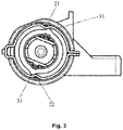
Fig. 3 shows a structural side view of another state of the embodiment of the invention. - The description on signs of the drawings: 1-outer cylinder; 2-limiting clamp spring; 21-first convex rib; 22-second convex rib; 3-positioning sleeve; 31-shifting piece; 4-rotating shaft.
- A preferred embodiment of the invention is introduced below with reference to the drawings of the description to make its technical contents clearer and convenient to understand.
- As shown in
Fig. 1 to Fig. 3 , the invention discloses a top mount self-locking mechanism, including an outer cylinder 1, a limitingclamp spring 2, a rotating shaft 4 and a positioning sleeve 3; the limitingclamp spring 2 is arranged in the outer cylinder 1 in a sleeved mode, the rotating shaft 4 is arranged at an axis part of the outer cylinder 1, and the positioning sleeve 3 is arranged on the rotating shaft 4 in a sleeving mode and moves along with the rotating shaft 4, wherein, the limitingclamp spring 2 is annular and includes afirst convex bulge 21 and asecond convex bulge 22, and thefirst convex bulge 21 and thesecond convex bulge 22 face the rotating shaft 4 and are arranged on a longitudinal position of the limitingclamp spring 2; and shiftingstructures 31 are arranged on an outer side of the positioning sleeve 3 and located between thefirst convex bulge 21 and thesecond convex bulge 22. - In an embodiment, the rotating shaft 4 is mounted in a center of an inner cavity of the outer cylinder 1 and can rotate at random axially. In general, the rotating shaft 4 is connected with a toilet cover plate or a seat ring thereof, when the cover plate or the seat ring is lifted, the rotating shaft 4 drives the positioning sleeve 3 to rotate in a clockwise direction shown in
Fig. 2 , and when the shiftingpieces 31 outside the positioning sleeve 3 cross thefirst convex rib 21 and thesecond convex rib 22, the cover plate or the seat ring is positioned. When there is a need to put it down, the cover plate or the seat ring is directly pressed to make theshifting pieces 31 reversely cross thefirst convex rib 21 and thesecond convex rib 22, and then the cover plate or the seat ring can be put down. - Further, there are two shifting
pieces 31, and the two shiftingpieces 31 are arranged on the two sides of the positioning sleeve 3 respectively. Preferably, the positions of the shiftingpieces 31 are perpendicular to the positions of thefirst convex rib 21 and thesecond convex rib 22, and then the cover plate or the seat ring can be fixed after being overturned into a perpendicular state. - Further, the rotating shaft 4 is a damper. Thus, when the top mount part falls, a slow-descending function of the top mount part is provided.
- Further, the limiting
clamp spring 2 is made of spring steel, which has high elasticity, high strength and high rebound elasticity, so that the limited shiftingpieces 31 cross or are separated from thefirst convex rib 21 and thesecond convex rib 22. - Further, the positioning sleeve 3 is made of nylon resin, which has the characteristics of high toughness and high abrasive resistance, so that the
shifting pieces 31 on the positioning sleeve 3 cross or are separated from thefirst convex rib 21 and thesecond convex rib 22 better when the positioning sleeve 3 rotates.
Claims (5)
- A top mount self-locking mechanism, characterized in that the top mount self-locking mechanism comprises an outer cylinder, a limiting clamp spring, a rotating shaft and a positioning sleeve; the limiting clamp spring is arranged in the outer cylinder in a sleeved mode, the rotating shaft is arranged at an axis part of the outer cylinder, and the positioning sleeve is arranged on the rotating shaft in a sleeving mode and moves along with the rotating shaft, wherein,
the limiting clamp spring is annular and comprises a first convex rib and a second convex rib, and the first convex rib and the second convex rib face the rotating shaft and are arranged on a longitudinal position of the limiting clamp spring; and shifting pieces are arranged on an outer side of the positioning sleeve and located between the first convex rib and the second convex rib. - The top mount self-locking mechanism according to claim 1, characterized in that there are two shifting pieces, and the two shifting pieces are arranged on two sides of the positioning sleeve respectively.
- The top mount self-locking mechanism according to claim 1 or 2, characterized in that the rotating shaft is a damper.
- The top mount self-locking mechanism according to one of the preceding claims, characterized in that the limiting clamp spring is made of spring steel.
- The top mount self-locking mechanism according to one of the preceding claims, characterized in that the positioning sleeve is made of nylon resin.
Applications Claiming Priority (1)
| Application Number | Priority Date | Filing Date | Title |
|---|---|---|---|
| CN202022415038.9U CN213821205U (en) | 2020-10-27 | 2020-10-27 | Self-locking mechanism for cover plate |
Publications (2)
| Publication Number | Publication Date |
|---|---|
| EP3992404A1 true EP3992404A1 (en) | 2022-05-04 |
| EP3992404B1 EP3992404B1 (en) | 2024-08-14 |
Family
ID=77011295
Family Applications (1)
| Application Number | Title | Priority Date | Filing Date |
|---|---|---|---|
| EP21204774.0A Active EP3992404B1 (en) | 2020-10-27 | 2021-10-26 | Top mount self-locking mechanism |
Country Status (2)
| Country | Link |
|---|---|
| EP (1) | EP3992404B1 (en) |
| CN (1) | CN213821205U (en) |
Citations (2)
| Publication number | Priority date | Publication date | Assignee | Title |
|---|---|---|---|---|
| US5769188A (en) * | 1994-12-27 | 1998-06-23 | Tok Bearing Co., Ltd. | Rotary damper with self-standing mechanism |
| CN208211961U (en) * | 2017-07-31 | 2018-12-11 | 厦门瑞尔特卫浴科技股份有限公司 | A kind of slow drop positioner of water-closet bowl cover plate |
-
2020
- 2020-10-27 CN CN202022415038.9U patent/CN213821205U/en active Active
-
2021
- 2021-10-26 EP EP21204774.0A patent/EP3992404B1/en active Active
Patent Citations (2)
| Publication number | Priority date | Publication date | Assignee | Title |
|---|---|---|---|---|
| US5769188A (en) * | 1994-12-27 | 1998-06-23 | Tok Bearing Co., Ltd. | Rotary damper with self-standing mechanism |
| CN208211961U (en) * | 2017-07-31 | 2018-12-11 | 厦门瑞尔特卫浴科技股份有限公司 | A kind of slow drop positioner of water-closet bowl cover plate |
Also Published As
| Publication number | Publication date |
|---|---|
| EP3992404B1 (en) | 2024-08-14 |
| CN213821205U (en) | 2021-07-30 |
Similar Documents
| Publication | Publication Date | Title |
|---|---|---|
| US2556003A (en) | Water glass and cup washer | |
| CA2894121C (en) | Cup holder for chair | |
| CN212326650U (en) | Electric tooth brush | |
| EP3992404B1 (en) | Top mount self-locking mechanism | |
| CN201395187Y (en) | Rubber seat cover | |
| CN208470041U (en) | Shock-absorbing folding bicycle and its switching device | |
| CN207382381U (en) | A kind of mobile phone gimbal | |
| CN207931727U (en) | A kind of motor-car high ferro train special-purpose closestool | |
| CN208403770U (en) | A kind of cup type stool | |
| US1789439A (en) | Desk novelty | |
| CN210432615U (en) | Portable pet accompanying cup | |
| CN204363750U (en) | Fine grinding assembly and soybean milk machine | |
| CN217218880U (en) | Toilet brush fixing frame | |
| CN108189854B (en) | A special toilet for high-speed trains | |
| CN223730873U (en) | Umbrella with high-strength glass fiber rib | |
| CN205632234U (en) | Car interior centre gripping type saucer | |
| CN203864514U (en) | Vehicle ash pan cup holder | |
| CN205513529U (en) | It easily pulls chair to fit old type | |
| CN208388266U (en) | A kind of height-adjustable children dinning chair | |
| CN223887127U (en) | Sitting fumigation chair convenient to clean and use medicine | |
| CN219662856U (en) | Magnetic fluid device embedded in toy for visual jumping along with sound | |
| CN202262923U (en) | Hand-type bathing handle | |
| CN105832150B (en) | fine grinding assembly and soybean milk machine | |
| CN208264038U (en) | A kind of regulation handle of automotive seat | |
| CN2190481Y (en) | Cold-proof pad for toilet closet |
Legal Events
| Date | Code | Title | Description |
|---|---|---|---|
| PUAI | Public reference made under article 153(3) epc to a published international application that has entered the european phase |
Free format text: ORIGINAL CODE: 0009012 |
|
| STAA | Information on the status of an ep patent application or granted ep patent |
Free format text: STATUS: THE APPLICATION HAS BEEN PUBLISHED |
|
| AK | Designated contracting states |
Kind code of ref document: A1 Designated state(s): AL AT BE BG CH CY CZ DE DK EE ES FI FR GB GR HR HU IE IS IT LI LT LU LV MC MK MT NL NO PL PT RO RS SE SI SK SM TR |
|
| STAA | Information on the status of an ep patent application or granted ep patent |
Free format text: STATUS: REQUEST FOR EXAMINATION WAS MADE |
|
| 17P | Request for examination filed |
Effective date: 20220519 |
|
| RBV | Designated contracting states (corrected) |
Designated state(s): AL AT BE BG CH CY CZ DE DK EE ES FI FR GB GR HR HU IE IS IT LI LT LU LV MC MK MT NL NO PL PT RO RS SE SI SK SM TR |
|
| GRAP | Despatch of communication of intention to grant a patent |
Free format text: ORIGINAL CODE: EPIDOSNIGR1 |
|
| STAA | Information on the status of an ep patent application or granted ep patent |
Free format text: STATUS: GRANT OF PATENT IS INTENDED |
|
| INTG | Intention to grant announced |
Effective date: 20240506 |
|
| GRAS | Grant fee paid |
Free format text: ORIGINAL CODE: EPIDOSNIGR3 |
|
| GRAA | (expected) grant |
Free format text: ORIGINAL CODE: 0009210 |
|
| STAA | Information on the status of an ep patent application or granted ep patent |
Free format text: STATUS: THE PATENT HAS BEEN GRANTED |
|
| AK | Designated contracting states |
Kind code of ref document: B1 Designated state(s): AL AT BE BG CH CY CZ DE DK EE ES FI FR GB GR HR HU IE IS IT LI LT LU LV MC MK MT NL NO PL PT RO RS SE SI SK SM TR |
|
| REG | Reference to a national code |
Ref country code: GB Ref legal event code: FG4D |
|
| REG | Reference to a national code |
Ref country code: CH Ref legal event code: EP |
|
| REG | Reference to a national code |
Ref country code: DE Ref legal event code: R096 Ref document number: 602021017128 Country of ref document: DE |
|
| REG | Reference to a national code |
Ref country code: IE Ref legal event code: FG4D Ref country code: NL Ref legal event code: FP |
|
| P01 | Opt-out of the competence of the unified patent court (upc) registered |
Free format text: CASE NUMBER: APP_46802/2024 Effective date: 20240813 |
|
| REG | Reference to a national code |
Ref country code: LT Ref legal event code: MG9D |
|
| REG | Reference to a national code |
Ref country code: AT Ref legal event code: UEP Ref document number: 1713448 Country of ref document: AT Kind code of ref document: T Effective date: 20240814 |
|
| PG25 | Lapsed in a contracting state [announced via postgrant information from national office to epo] |
Ref country code: NO Free format text: LAPSE BECAUSE OF FAILURE TO SUBMIT A TRANSLATION OF THE DESCRIPTION OR TO PAY THE FEE WITHIN THE PRESCRIBED TIME-LIMIT Effective date: 20241114 |
|
| PG25 | Lapsed in a contracting state [announced via postgrant information from national office to epo] |
Ref country code: FI Free format text: LAPSE BECAUSE OF FAILURE TO SUBMIT A TRANSLATION OF THE DESCRIPTION OR TO PAY THE FEE WITHIN THE PRESCRIBED TIME-LIMIT Effective date: 20240814 Ref country code: PT Free format text: LAPSE BECAUSE OF FAILURE TO SUBMIT A TRANSLATION OF THE DESCRIPTION OR TO PAY THE FEE WITHIN THE PRESCRIBED TIME-LIMIT Effective date: 20241216 Ref country code: GR Free format text: LAPSE BECAUSE OF FAILURE TO SUBMIT A TRANSLATION OF THE DESCRIPTION OR TO PAY THE FEE WITHIN THE PRESCRIBED TIME-LIMIT Effective date: 20241115 Ref country code: PL Free format text: LAPSE BECAUSE OF FAILURE TO SUBMIT A TRANSLATION OF THE DESCRIPTION OR TO PAY THE FEE WITHIN THE PRESCRIBED TIME-LIMIT Effective date: 20240814 |
|
| PG25 | Lapsed in a contracting state [announced via postgrant information from national office to epo] |
Ref country code: BG Free format text: LAPSE BECAUSE OF FAILURE TO SUBMIT A TRANSLATION OF THE DESCRIPTION OR TO PAY THE FEE WITHIN THE PRESCRIBED TIME-LIMIT Effective date: 20240814 |
|
| PG25 | Lapsed in a contracting state [announced via postgrant information from national office to epo] |
Ref country code: LV Free format text: LAPSE BECAUSE OF FAILURE TO SUBMIT A TRANSLATION OF THE DESCRIPTION OR TO PAY THE FEE WITHIN THE PRESCRIBED TIME-LIMIT Effective date: 20240814 |
|
| PG25 | Lapsed in a contracting state [announced via postgrant information from national office to epo] |
Ref country code: IS Free format text: LAPSE BECAUSE OF FAILURE TO SUBMIT A TRANSLATION OF THE DESCRIPTION OR TO PAY THE FEE WITHIN THE PRESCRIBED TIME-LIMIT Effective date: 20241214 |
|
| PG25 | Lapsed in a contracting state [announced via postgrant information from national office to epo] |
Ref country code: HR Free format text: LAPSE BECAUSE OF FAILURE TO SUBMIT A TRANSLATION OF THE DESCRIPTION OR TO PAY THE FEE WITHIN THE PRESCRIBED TIME-LIMIT Effective date: 20240814 |
|
| PG25 | Lapsed in a contracting state [announced via postgrant information from national office to epo] |
Ref country code: RS Free format text: LAPSE BECAUSE OF FAILURE TO SUBMIT A TRANSLATION OF THE DESCRIPTION OR TO PAY THE FEE WITHIN THE PRESCRIBED TIME-LIMIT Effective date: 20241114 Ref country code: ES Free format text: LAPSE BECAUSE OF FAILURE TO SUBMIT A TRANSLATION OF THE DESCRIPTION OR TO PAY THE FEE WITHIN THE PRESCRIBED TIME-LIMIT Effective date: 20240814 |
|
| PG25 | Lapsed in a contracting state [announced via postgrant information from national office to epo] |
Ref country code: RS Free format text: LAPSE BECAUSE OF FAILURE TO SUBMIT A TRANSLATION OF THE DESCRIPTION OR TO PAY THE FEE WITHIN THE PRESCRIBED TIME-LIMIT Effective date: 20241114 Ref country code: PT Free format text: LAPSE BECAUSE OF FAILURE TO SUBMIT A TRANSLATION OF THE DESCRIPTION OR TO PAY THE FEE WITHIN THE PRESCRIBED TIME-LIMIT Effective date: 20241216 Ref country code: PL Free format text: LAPSE BECAUSE OF FAILURE TO SUBMIT A TRANSLATION OF THE DESCRIPTION OR TO PAY THE FEE WITHIN THE PRESCRIBED TIME-LIMIT Effective date: 20240814 Ref country code: NO Free format text: LAPSE BECAUSE OF FAILURE TO SUBMIT A TRANSLATION OF THE DESCRIPTION OR TO PAY THE FEE WITHIN THE PRESCRIBED TIME-LIMIT Effective date: 20241114 Ref country code: LV Free format text: LAPSE BECAUSE OF FAILURE TO SUBMIT A TRANSLATION OF THE DESCRIPTION OR TO PAY THE FEE WITHIN THE PRESCRIBED TIME-LIMIT Effective date: 20240814 Ref country code: IS Free format text: LAPSE BECAUSE OF FAILURE TO SUBMIT A TRANSLATION OF THE DESCRIPTION OR TO PAY THE FEE WITHIN THE PRESCRIBED TIME-LIMIT Effective date: 20241214 Ref country code: HR Free format text: LAPSE BECAUSE OF FAILURE TO SUBMIT A TRANSLATION OF THE DESCRIPTION OR TO PAY THE FEE WITHIN THE PRESCRIBED TIME-LIMIT Effective date: 20240814 Ref country code: GR Free format text: LAPSE BECAUSE OF FAILURE TO SUBMIT A TRANSLATION OF THE DESCRIPTION OR TO PAY THE FEE WITHIN THE PRESCRIBED TIME-LIMIT Effective date: 20241115 Ref country code: FI Free format text: LAPSE BECAUSE OF FAILURE TO SUBMIT A TRANSLATION OF THE DESCRIPTION OR TO PAY THE FEE WITHIN THE PRESCRIBED TIME-LIMIT Effective date: 20240814 Ref country code: ES Free format text: LAPSE BECAUSE OF FAILURE TO SUBMIT A TRANSLATION OF THE DESCRIPTION OR TO PAY THE FEE WITHIN THE PRESCRIBED TIME-LIMIT Effective date: 20240814 Ref country code: BG Free format text: LAPSE BECAUSE OF FAILURE TO SUBMIT A TRANSLATION OF THE DESCRIPTION OR TO PAY THE FEE WITHIN THE PRESCRIBED TIME-LIMIT Effective date: 20240814 |
|
| REG | Reference to a national code |
Ref country code: DE Ref legal event code: R082 Ref document number: 602021017128 Country of ref document: DE Representative=s name: SZYNKA SMORODIN PATENTANWAELTE PARTNERSCHAFT M, DE |
|
| PG25 | Lapsed in a contracting state [announced via postgrant information from national office to epo] |
Ref country code: DK Free format text: LAPSE BECAUSE OF FAILURE TO SUBMIT A TRANSLATION OF THE DESCRIPTION OR TO PAY THE FEE WITHIN THE PRESCRIBED TIME-LIMIT Effective date: 20240814 Ref country code: SM Free format text: LAPSE BECAUSE OF FAILURE TO SUBMIT A TRANSLATION OF THE DESCRIPTION OR TO PAY THE FEE WITHIN THE PRESCRIBED TIME-LIMIT Effective date: 20240814 Ref country code: RO Free format text: LAPSE BECAUSE OF FAILURE TO SUBMIT A TRANSLATION OF THE DESCRIPTION OR TO PAY THE FEE WITHIN THE PRESCRIBED TIME-LIMIT Effective date: 20240814 |
|
| PG25 | Lapsed in a contracting state [announced via postgrant information from national office to epo] |
Ref country code: EE Free format text: LAPSE BECAUSE OF FAILURE TO SUBMIT A TRANSLATION OF THE DESCRIPTION OR TO PAY THE FEE WITHIN THE PRESCRIBED TIME-LIMIT Effective date: 20240814 |
|
| PG25 | Lapsed in a contracting state [announced via postgrant information from national office to epo] |
Ref country code: CZ Free format text: LAPSE BECAUSE OF FAILURE TO SUBMIT A TRANSLATION OF THE DESCRIPTION OR TO PAY THE FEE WITHIN THE PRESCRIBED TIME-LIMIT Effective date: 20240814 |
|
| PG25 | Lapsed in a contracting state [announced via postgrant information from national office to epo] |
Ref country code: SK Free format text: LAPSE BECAUSE OF FAILURE TO SUBMIT A TRANSLATION OF THE DESCRIPTION OR TO PAY THE FEE WITHIN THE PRESCRIBED TIME-LIMIT Effective date: 20240814 |
|
| REG | Reference to a national code |
Ref country code: DE Ref legal event code: R097 Ref document number: 602021017128 Country of ref document: DE |
|
| PLBE | No opposition filed within time limit |
Free format text: ORIGINAL CODE: 0009261 |
|
| STAA | Information on the status of an ep patent application or granted ep patent |
Free format text: STATUS: NO OPPOSITION FILED WITHIN TIME LIMIT |
|
| PG25 | Lapsed in a contracting state [announced via postgrant information from national office to epo] |
Ref country code: MC Free format text: LAPSE BECAUSE OF FAILURE TO SUBMIT A TRANSLATION OF THE DESCRIPTION OR TO PAY THE FEE WITHIN THE PRESCRIBED TIME-LIMIT Effective date: 20240814 |
|
| PG25 | Lapsed in a contracting state [announced via postgrant information from national office to epo] |
Ref country code: BE Free format text: LAPSE BECAUSE OF NON-PAYMENT OF DUE FEES Effective date: 20241031 Ref country code: LU Free format text: LAPSE BECAUSE OF NON-PAYMENT OF DUE FEES Effective date: 20241026 |
|
| 26N | No opposition filed |
Effective date: 20250515 |
|
| REG | Reference to a national code |
Ref country code: BE Ref legal event code: MM Effective date: 20241031 |
|
| PG25 | Lapsed in a contracting state [announced via postgrant information from national office to epo] |
Ref country code: SE Free format text: LAPSE BECAUSE OF FAILURE TO SUBMIT A TRANSLATION OF THE DESCRIPTION OR TO PAY THE FEE WITHIN THE PRESCRIBED TIME-LIMIT Effective date: 20240814 |
|
| PG25 | Lapsed in a contracting state [announced via postgrant information from national office to epo] |
Ref country code: IE Free format text: LAPSE BECAUSE OF NON-PAYMENT OF DUE FEES Effective date: 20241026 |
|
| REG | Reference to a national code |
Ref country code: CH Ref legal event code: U11 Free format text: ST27 STATUS EVENT CODE: U-0-0-U10-U11 (AS PROVIDED BY THE NATIONAL OFFICE) Effective date: 20251101 |
|
| PGFP | Annual fee paid to national office [announced via postgrant information from national office to epo] |
Ref country code: NL Payment date: 20251023 Year of fee payment: 5 |
|
| PGFP | Annual fee paid to national office [announced via postgrant information from national office to epo] |
Ref country code: DE Payment date: 20251020 Year of fee payment: 5 |
|
| PGFP | Annual fee paid to national office [announced via postgrant information from national office to epo] |
Ref country code: GB Payment date: 20251024 Year of fee payment: 5 |
|
| PGFP | Annual fee paid to national office [announced via postgrant information from national office to epo] |
Ref country code: AT Payment date: 20260113 Year of fee payment: 5 |
|
| PGFP | Annual fee paid to national office [announced via postgrant information from national office to epo] |
Ref country code: IT Payment date: 20251031 Year of fee payment: 5 |
|
| PGFP | Annual fee paid to national office [announced via postgrant information from national office to epo] |
Ref country code: FR Payment date: 20251029 Year of fee payment: 5 |
|
| PGFP | Annual fee paid to national office [announced via postgrant information from national office to epo] |
Ref country code: CH Payment date: 20251101 Year of fee payment: 5 |
|
| PG25 | Lapsed in a contracting state [announced via postgrant information from national office to epo] |
Ref country code: CY Free format text: LAPSE BECAUSE OF FAILURE TO SUBMIT A TRANSLATION OF THE DESCRIPTION OR TO PAY THE FEE WITHIN THE PRESCRIBED TIME-LIMIT; INVALID AB INITIO Effective date: 20211026 |
|
| PG25 | Lapsed in a contracting state [announced via postgrant information from national office to epo] |
Ref country code: HU Free format text: LAPSE BECAUSE OF FAILURE TO SUBMIT A TRANSLATION OF THE DESCRIPTION OR TO PAY THE FEE WITHIN THE PRESCRIBED TIME-LIMIT; INVALID AB INITIO Effective date: 20211026 |