EP3992349A1 - Clothing treatment apparatus - Google Patents
Clothing treatment apparatus Download PDFInfo
- Publication number
- EP3992349A1 EP3992349A1 EP20833419.3A EP20833419A EP3992349A1 EP 3992349 A1 EP3992349 A1 EP 3992349A1 EP 20833419 A EP20833419 A EP 20833419A EP 3992349 A1 EP3992349 A1 EP 3992349A1
- Authority
- EP
- European Patent Office
- Prior art keywords
- clothing treatment
- sealing
- wall
- annular sealing
- treatment apparatus
- Prior art date
- Legal status (The legal status is an assumption and is not a legal conclusion. Google has not performed a legal analysis and makes no representation as to the accuracy of the status listed.)
- Granted
Links
Images



Classifications
-
- D—TEXTILES; PAPER
- D06—TREATMENT OF TEXTILES OR THE LIKE; LAUNDERING; FLEXIBLE MATERIALS NOT OTHERWISE PROVIDED FOR
- D06F—LAUNDERING, DRYING, IRONING, PRESSING OR FOLDING TEXTILE ARTICLES
- D06F39/00—Details of washing machines not specific to a single type of machines covered by groups D06F9/00 - D06F27/00
- D06F39/02—Devices for adding soap or other washing agents
-
- D—TEXTILES; PAPER
- D06—TREATMENT OF TEXTILES OR THE LIKE; LAUNDERING; FLEXIBLE MATERIALS NOT OTHERWISE PROVIDED FOR
- D06F—LAUNDERING, DRYING, IRONING, PRESSING OR FOLDING TEXTILE ARTICLES
- D06F39/00—Details of washing machines not specific to a single type of machines covered by groups D06F9/00 - D06F27/00
- D06F39/02—Devices for adding soap or other washing agents
- D06F39/022—Devices for adding soap or other washing agents in a liquid state
-
- Y—GENERAL TAGGING OF NEW TECHNOLOGICAL DEVELOPMENTS; GENERAL TAGGING OF CROSS-SECTIONAL TECHNOLOGIES SPANNING OVER SEVERAL SECTIONS OF THE IPC; TECHNICAL SUBJECTS COVERED BY FORMER USPC CROSS-REFERENCE ART COLLECTIONS [XRACs] AND DIGESTS
- Y02—TECHNOLOGIES OR APPLICATIONS FOR MITIGATION OR ADAPTATION AGAINST CLIMATE CHANGE
- Y02B—CLIMATE CHANGE MITIGATION TECHNOLOGIES RELATED TO BUILDINGS, e.g. HOUSING, HOUSE APPLIANCES OR RELATED END-USER APPLICATIONS
- Y02B40/00—Technologies aiming at improving the efficiency of home appliances, e.g. induction cooking or efficient technologies for refrigerators, freezers or dish washers
Definitions
- the present invention belongs to the field of clothing treatment technologies, and particularly, provides a clothing treatment apparatus.
- Clothing treatment apparatuses are machines capable of washing, spin-drying, dry-cleaning and/or drying clothing.
- Common clothing treatment apparatuses include washing machines, shoe washing machines, clothes dryers, dry-cleaning machines, washing and drying machines. Taking a washing machine as an example, to ensure washing effect of clothing, a detergent/washing powder is often added to water before washing clothing to remove dirt and/or grease stains from the clothing by using a surfactant.
- a washing machine is usually provided with a detergent dispensing apparatus by which a detergent can be dispensed into a washing cavity of the washing machine.
- the detergent dispensing apparatus is generally a drawer type detergent dispensing apparatus.
- the washing machine is usually provided with an accommodating box, the detergent dispensing apparatus is arranged in the accommodating box and is slidably connected to the accommodating box.
- the detergent dispensing apparatus can be pulled out of the accommodating box before injecting the detergent into the detergent dispensing apparatus.
- detergent may be spilled, and spilled detergent will flow into the accommodating box along the detergent dispensing apparatus.
- the present invention provides a clothing treatment apparatus, including an accommodating member and a clothing treatment agent dispensing apparatus provided in the accommodating member, the clothing treatment agent dispensing apparatus is slidably connected to the accommodating member; a water channel is formed between an outer wall of the clothing treatment agent dispensing apparatus and an inner wall of the accommodating member; and a water outlet is formed on the accommodating member, and is communicated with the water channel.
- the water channel includes a first water channel formed between an outer side wall of the clothing treatment agent dispensing apparatus and an inner side wall of the accommodating member.
- the water channel further includes a second water channel formed between an outer rear wall of the clothing treatment agent dispensing apparatus and an inner rear wall of the accommodating member.
- the first water channel is communicated with the second water channel.
- the water outlet is formed on a bottom plate of the accommodating member.
- the bottom plate is obliquely provided and the water outlet is located at a lower end of the bottom plate to enable all water in the water channel to flow to the water outlet.
- the clothing treatment agent dispensing apparatus includes a storage container, a dispensing container and a liquid delivery tube, the storage container is secured in the accommodating member, the dispensing container is slidably connected to the accommodating member, one end of the liquid delivery tube is communicated with the dispensing container, the other end of the liquid delivery tube is inserted into the storage container, and a length of the liquid delivery tube is configured so that the other end of the liquid delivery tube does not come out of the storage container when the dispensing container moves away from the storage container.
- the storage container is provided with a guide structure, and the other end of the liquid delivery tube is inserted through the guide structure into the storage container.
- the clothing treatment agent dispensing apparatus further includes a sealing member, the sealing member includes a main body part, and a first sealing portion and a second sealing portion formed on the main body part, the first sealing portion is hermetically affixed to an outer wall of the liquid delivery tube, and the sealing member is hermetically connected to the guide structure through the second sealing portion.
- the sealing member is a sealing ring, and a main body part of the sealing ring has an inner diameter larger than an outer diameter of the liquid delivery tube.
- the first sealing portion is a sealing lip formed on an inner wall of the main body part of the sealing ring.
- the sealing lip is obliquely provided in a direction from the dispensing container to the storage container.
- the sealing ring is hermetically connected to an outer wall of the guide structure through the second sealing portion.
- the second sealing portion includes at least one annular sealing rib or sealing groove formed on the inner wall of the main body part of the sealing ring, at least one annular sealing groove or sealing rib is correspondingly provided on the outer wall of the guide structure, the annular sealing rib is in a one-to-one correspondence with the annular sealing groove, and the annular sealing rib is in a transition fit or interference fit with the annular sealing groove to hermetically seal the sealing ring and the guide structure.
- the second sealing portion includes a first annular sealing rib and a second annular sealing rib formed on the inner wall of the main body part of the sealing ring, a first annular sealing groove and a second annular sealing groove are correspondingly provided on the outer wall of the guide structure, the first annular sealing rib is in a transition fit or interference fit with the first annular sealing groove, and the second annular sealing rib is in a transition fit or interference fit with the second annular sealing groove.
- the second sealing portion includes at least one annular sealing rib or sealing groove formed on an outer wall of the main body part of the sealing ring, at least one annular sealing groove or sealing rib is correspondingly provided on an inner wall of the guide structure, the annular sealing rib is in a one-to-one correspondence with the annular sealing groove, and the annular sealing rib is in a transition fit or interference fit with the annular sealing groove to hermetically seal the sealing ring and the guide structure.
- the guide structure is a guide pipe fitting formed on an outer wall of the storage container.
- the accommodating member is an accommodating box.
- the clothing treatment apparatus is a washing machine
- the clothing treatment agent dispensing apparatus is a dispensing box for dispensing a detergent or a conditioner.
- the clothing treatment apparatus greatly simplifies a process of cleaning the accommodating member, and improves user experience.
- the accommodating member is provided with a water outlet in communication with the water channel, so that water in the water channel can be drained.
- the first water channel is communicated with the second water channel, in this case, only one water outlet is required for convenient design and machining, which can reduce cost.
- the bottom plate is obliquely provided and the water outlet is located at a lower end of the bottom plate to enable all water in the water channel to flow to the water outlet.
- the clothing treatment agent dispensing apparatus is provided with a split structure, that is, the storage container and the dispensing container are provided separately, and only the dispensing container is slidably connected to the accommodating member, so that a user only needs to pull out the dispensing container without pulling out the storage container when the user dispenses a clothing treatment agent, which is labor-saving and fast.
- a liquid delivery tube is arranged between the dispensing container and the storage container, and one end of the liquid delivery tube extends into the storage container. When the dispensing container is pulled, the liquid delivery tube moves with the dispensing container, but the other end of the liquid delivery tube will not come out of the storage container, so that the liquid delivery tube always allows the dispensing container to be communicated with the storage container. Therefore, when a clothing treatment agent is injected into the dispensing container, the clothing treatment agent can be delivered to the storage container through the liquid delivery tube.
- the liquid delivery tube is inserted into the storage container through a guide structure provided on the storage container.
- the guide structure is configured to guide the liquid delivery tube to prevent the liquid delivery tube from deviation in a moving process, thereby improving the reliability of the clothing treatment agent dispensing apparatus.
- the main body part of the sealing ring has an inner diameter larger than an outer diameter of the liquid delivery tube.
- the first sealing portion is a sealing lip formed on an inner wall of a sealing ring.
- the sealing lip is hermetically affixed to an outer wall of the liquid delivery tube, so that a clothing treatment agent in the storage container can be prevented from leaking along the outer wall of the liquid delivery tube, and when the liquid delivery tube is pulled out, the sealing lip can scrape off the clothing treatment agent adhered to the outer wall of the liquid delivery tube to prevent the clothing treatment agent from leaking.
- the sealing lip is obliquely provided in a direction from the dispensing container to the storage container.
- the sealing ring is hermetically connected to an outer wall of the guide structure through the second sealing portion.
- movement of the liquid delivery tube can be prevented from being influenced by an excessive friction on the outer wall of the liquid delivery tube, and sealability of the sealing ring can be improved.
- the sealing ring is provided between the inner wall of the guide structure and the outer wall of the liquid delivery tube, movement of the liquid delivery tube will be influenced by a large friction on the outer wall of the liquid delivery tube. Therefore, the sealing ring can be hermetically connected to the outer wall of the guide structure to prevent a large friction on the outer wall of the liquid delivery tube.
- the clothing treatment agent in the storage container flows to the sealing ring along a gap between the liquid delivery tube and the guide structure, and can leak from a possible gap between the sealing ring and the outer wall of the guide structure by reverse flow, thereby improving the sealability of the sealing ring.
- annular sealing rib is in a transition fit or interference fit with the annular sealing groove.
- the second sealing portion includes a first annular sealing rib and a second annular sealing rib formed on the inner wall of the main body part of the sealing ring, a first annular sealing groove and a second annular sealing groove are correspondingly provided on the outer wall of the guide structure, the first annular sealing rib is in a transition fit or interference fit with the first annular sealing groove, and the second annular sealing rib is in a transition fit or interference fit with the second annular sealing groove.
- a double protection effect can be provided, that is, after one set of annular sealing ribs and annular sealing grooves fails, the sealing ring can be hermetically connected to the guide pipe fitting through another set of annular sealing ribs and annular sealing grooves, thereby further improving the connection stability and sealability between the sealing ring and the guide pipe fitting.
- an orientation or positional relationship indicated by the terms “left”, “right”, “inner”, “outer” and the like is an orientation or positional relationship shown based on the accompanying drawings, is intended only to facilitate the description rather than indicating or implying that the device or element must have a specific orientation, or be constructed and operated in a specific orientation, and therefore should not be construed as a limitation to the present invention.
- the terms “first” and “second” are used for descriptive purposes only and are not to be construed as indicating or implying a relative importance.
- the terms “arranged”, “installed”, “connection” and “connected” should be understood in a broad sense, which, for example, may be understood as fixed connection, detachable connection or integral connection; may be understood as mechanical connection or electrical connection; or may be understood as direct connection, indirect connection via an intermediate medium, or communication between the interiors of two elements.
- the specific meanings of the above terms in the present invention can be understood in specific cases by a person skilled in the art.
- an accommodating box for installing a clothing treatment agent dispensing apparatus of an existing washing machine is inconvenient to clean, which leads to a problem of poor user experience.
- the present invention provides a washing machine designed to enable a user to clean an accommodating box more conveniently, so as to improve user experience.
- the washing machine of the present invention includes an accommodating member 1 and a clothing treatment agent dispensing apparatus provided in the accommodating member 1, the clothing treatment agent dispensing apparatus is slidably connected to the accommodating member 1; a water channel 2 is formed between an outer wall of the clothing treatment agent dispensing apparatus and an inner wall of the accommodating member 1; and a water outlet 3 is formed on the accommodating member 1, and is communicated with the water channel 2.
- a water channel 2 between the outer wall of the clothing treatment agent dispensing apparatus and the inner wall of the accommodating member 1, it is unnecessary to take the clothing treatment agent dispensing apparatus out of the accommodating member 1 when the accommodating member 1 needs to be cleaned, and water can be directly injected to the water channel 2 to clean both the accommodating member 1 and the outer wall of the clothing treatment agent dispensing apparatus.
- a water outlet 3 is formed on the accommodating member 1, and is communicated with the water channel 2, so that water in the water channel 2 can be drained.
- the accommodating member 1 is an accommodating box, and the clothing treatment agent dispensing apparatus is provided in the accommodating box and slidably connected to the accommodating box.
- the accommodating member 1 may also be provided as an accommodating bucket or an accommodating box. Such adjustment and change to a specific structural form of the accommodating member 1 do not deviate from the principle and scope of the present invention, and should be limited within the protection scope of the present invention.
- the clothing treatment agent may be a detergent, then the clothing treatment agent dispensing apparatus is a dispensing box for dispensing the detergent, alternatively, the clothing treatment agent may also be a conditioner, then the clothing treatment agent dispensing apparatus is a dispensing box for dispensing the conditioner, and so on.
- the clothing treatment agent may also be a conditioner, then the clothing treatment agent dispensing apparatus is a dispensing box for dispensing the conditioner, and so on.
- the water channel 2 includes a first water channel 21 formed between an outer side wall of the clothing treatment agent dispensing apparatus and an inner side wall of the accommodating member 1. Further preferably, the water channel 2 further includes a second water channel 22 formed between an outer rear wall of the clothing treatment agent dispensing apparatus and an inner rear wall of the accommodating member 1.
- the first water channel 21 is preferably communicated with the second water channel 22, in this case, only one water outlet 3 is required. Certainly, the first water channel 21 may not be communicated with the second water channel 22, in this case, it is necessary to provide two water outlets 3 connected to the first water channel 21 and the second water channel 22 respectively.
- the water outlet 3 is formed on a bottom plate 11 of the accommodating member 1.
- the water outlet 3 is formed on the bottom plate 11 to facilitate drainage of water from the accommodating member 1.
- the bottom plate 11 is obliquely provided and the water outlet 3 is located at a lower end of the bottom plate 11 to enable all water in the water channel 2 to flow to the water outlet 3, and avoid water remaining in the water channel 2.
- the clothing treatment agent dispensing apparatus includes a storage container 4, a dispensing container 5 and a liquid delivery tube 6, the storage container 4 is secured in the accommodating member 1, the dispensing container 5 is slidably connected to the accommodating member 1, one end of the liquid delivery tube 6 is communicated with the dispensing container 5, the other end of the liquid delivery tube 6 is inserted into the storage container 4, and a length of the liquid delivery tube 6 is configured so that the other end of the liquid delivery tube 6 does not come out of the storage container 4 when the dispensing container 5 moves away from the storage container 4.
- the clothing treatment agent dispensing apparatus is provided with a split structure, that is, the storage container 4 and the dispensing container 5 are provided separately, and only the dispensing container 5 is slidably connected to the accommodating member 1, so that a user only needs to pull out the dispensing container 5 without pulling out the storage container 4 when the user needs to add a clothing treatment agent, which improves user experience.
- the dispensing container 5 is communicated with the storage container 4 through the liquid delivery tube 6, and a right end of the liquid delivery tube 6 is inserted into the storage container 4, so that when the dispensing container 5 is pulled (as shown in the figures, the dispensing container 5 moves to the left), the liquid delivery tube 6 moves with the dispensing container 5, but the right end of the liquid delivery tube 6 does not come out of the storage container 4, so that the clothing treatment agent injected into the dispensing container 5 can be delivered into the storage container 4 through the liquid delivery tube 6.
- the user pushes the dispensing container 5 and the liquid delivery tube 6 together into the accommodating member 1 after adding the clothing treatment agent to allow a right part of the liquid delivery tube 6 to be reinserted into the storage container 4.
- the dispensing container 5 is provided with two dispensing cavities 51, one of which is a detergent dispensing cavity and the other is a conditioner dispensing cavity.
- the storage container 4 is provided with two storage cavities: a detergent storage cavity and a conditioner storage cavity, the detergent dispensing cavity is communicated with the detergent storage cavity through a liquid delivery tube 6, and the conditioner dispensing cavity is communicated with the conditioner storage cavity through another liquid delivery tube 6.
- the number of the dispensing cavities 51 is not limited to the above two, for example, the number of the dispensing cavities 51 may also be one or three. Such adjustment and change to a specific number of the dispensing cavities 51 do not deviate from the principle and scope of the present invention, and should be limited within the protection scope of the present invention.
- the clothing treatment agent dispensing apparatus can also be provided integrally, that is, the storage container 4 and the dispensing container 5 are fixedly connected or integrated, and in this case, the liquid delivery tube 6 can be omitted.
- the storage container 4 is provided with a guide structure 41, and the other end of the liquid delivery tube 6 extends into the storage container 4 through the guide structure 41.
- the guide structure 41 is a guide pipe fitting 41 formed on an outer wall of the storage container 4, and a right end of the liquid delivery tube 6 is inserted into the storage container 4 through the guide pipe fitting 41.
- the guide pipe fitting 41 guides the liquid delivery tube 6 when the liquid delivery tube 6 moves with the dispensing container 5.
- the guide structure 41 can also be provided as a guide rib, a guide tube or another structure. Such adjustment and change to a specific structural form of the guide structure 41 do not deviate from the principle and scope of the present invention, and should be limited within the protection scope of the present invention.
- the clothing treatment agent dispensing apparatus further includes a sealing member 7, the sealing member 7 includes a main body part, and a first sealing portion 71 and a second sealing portion 72 formed on the main body part, the first sealing portion 71 is hermetically affixed to an outer wall of the liquid delivery tube 6, and the sealing member 7 is hermetically connected to the guide pipe fitting 41 through the second sealing portion 72.
- the sealing member 7 is a sealing ring 7, and a main body part of the sealing ring 7 has an inner diameter larger than an outer diameter of the liquid delivery tube 6. With such an arrangement, the liquid delivery tube 6 can be smoothly inserted into the sealing ring 7.
- the first sealing portion 71 is a sealing lip 71 formed on an inner wall of the main body part of the sealing ring 7.
- the sealing lip 71 is hermetically affixed to an outer wall of the liquid delivery tube 6, so that a clothing treatment agent in the storage container 4 can be prevented from leaking along the outer wall of the liquid delivery tube 6, and when the liquid delivery tube 6 is pulled out, the sealing lip 71 can scrape off the clothing treatment agent adhered to the outer wall of the liquid delivery tube 6 to prevent the clothing treatment agent from leaking.
- the sealing lip 71 is obliquely provided in a direction from the dispensing container 5 to the storage container 4. With such an arrangement, the liquid delivery tube 6 can be smoothly inserted into the sealing ring 7, and the sealing lip 71 can have a better sealing effect.
- the sealing ring 7 is hermetically connected to an outer wall of the guide pipe fitting 41 through the second sealing portion 72.
- the second sealing portion 72 includes at least one annular sealing rib formed on the inner wall of the main body part of the sealing ring 7, at least one annular sealing groove is correspondingly provided on the outer wall of the guide pipe fitting 41, the annular sealing rib is in a one-to-one correspondence with the annular sealing groove, and the annular sealing rib is in a transition fit or interference fit with the annular sealing groove to hermetically seal the sealing ring 7 and the guide pipe fitting 41.
- the at least one annular sealing rib includes a first annular sealing rib 721 and a second annular sealing rib 722, and the at least one annular sealing groove includes a first annular sealing groove 411 and a second annular sealing groove 412.
- the first annular sealing rib 721 is in a transition fit or interference fit with the first annular sealing groove 411
- the second annular sealing rib 722 is in a transition fit or interference fit with the second annular sealing groove 412.
- the sealing ring 7 can be hermetically connected to the guide pipe fitting 41 through another set of annular sealing ribs and annular sealing grooves.
- the number of the annular sealing ribs and annular sealing grooves is not limited to the above two, for example, the number of the annular sealing ribs and annular sealing grooves may also be one or three. Such adjustment and change to a specific number of the annular sealing ribs and annular sealing grooves do not deviate from the principle and scope of the present invention, and should be limited within the protection scope of the present invention.
- the second sealing portion 72 may also include at least one annular sealing groove formed on the inner wall of the main body part of the sealing ring 7, at least one annular sealing rib is correspondingly provided on the outer wall of the guide pipe fitting 41, the annular sealing rib is in a one-to-one correspondence with the annular sealing groove, and the annular sealing rib is in a transition fit or interference fit with the annular sealing groove to hermetically seal the sealing ring 7 and the guide pipe fitting 41.
- the sealing ring 7 may also be hermetically connected to an inner wall of the guide pipe fitting 41 through the second sealing portion 72.
- the second sealing portion 72 includes at least one annular sealing rib or sealing groove formed on an outer wall of the main body part of the sealing ring 7, at least one annular sealing groove or sealing rib is correspondingly provided on the inner wall of the guide pipe fitting 41, the annular sealing rib is in a one-to-one correspondence with the annular sealing groove, and the annular sealing rib is in a transition fit or interference fit with the annular sealing groove to hermetically seal the sealing ring 7 and the guide pipe fitting 41.
Landscapes
- Engineering & Computer Science (AREA)
- Textile Engineering (AREA)
- Detail Structures Of Washing Machines And Dryers (AREA)
Abstract
Description
- The present invention belongs to the field of clothing treatment technologies, and particularly, provides a clothing treatment apparatus.
- Clothing treatment apparatuses are machines capable of washing, spin-drying, dry-cleaning and/or drying clothing. Common clothing treatment apparatuses include washing machines, shoe washing machines, clothes dryers, dry-cleaning machines, washing and drying machines. Taking a washing machine as an example, to ensure washing effect of clothing, a detergent/washing powder is often added to water before washing clothing to remove dirt and/or grease stains from the clothing by using a surfactant.
- In the prior art, a washing machine is usually provided with a detergent dispensing apparatus by which a detergent can be dispensed into a washing cavity of the washing machine. The detergent dispensing apparatus is generally a drawer type detergent dispensing apparatus. To facilitate the installation of the detergent dispensing apparatus, the washing machine is usually provided with an accommodating box, the detergent dispensing apparatus is arranged in the accommodating box and is slidably connected to the accommodating box. When a detergent needs to be added, the detergent dispensing apparatus can be pulled out of the accommodating box before injecting the detergent into the detergent dispensing apparatus. However, in a process of injecting a detergent into the detergent dispensing apparatus, detergent may be spilled, and spilled detergent will flow into the accommodating box along the detergent dispensing apparatus. Excessive detergent if any accumulated in the accommodating box will affect sliding of the detergent dispensing apparatus. Moreover, if detergent is accumulated in the accommodating box for a long time, bacteria may breed, so that the accommodating box needs to be cleaned regularly. However, it is necessary to take the detergent dispensing apparatus out of the accommodating box before cleaning the accommodating box, and then the detergent dispensing apparatus is installed into the accommodating box after cleaning the accommodating box. The whole process is very tedious and seriously affects user experience. Moreover, frequent removal and installation of the detergent dispensing apparatus out of and into the accommodating box tend to damage the detergent dispensing apparatus and/or the accommodating box, which will affect normal use of the detergent dispensing apparatus, especially after the detergent dispensing apparatus is damaged, which may cause detergent leakage.
- Therefore, a new clothing treatment apparatus is needed in the field to resolve the above problems.
- To resolve the above problems in the prior art, that is, to resolve a problem of poor user experience due to inconvenient cleaning of an accommodating box for installing a clothing treatment agent dispensing apparatus of an existing clothing treatment apparatus, the present invention provides a clothing treatment apparatus, including an accommodating member and a clothing treatment agent dispensing apparatus provided in the accommodating member, the clothing treatment agent dispensing apparatus is slidably connected to the accommodating member; a water channel is formed between an outer wall of the clothing treatment agent dispensing apparatus and an inner wall of the accommodating member; and a water outlet is formed on the accommodating member, and is communicated with the water channel.
- In a preferred technical solution for the clothing treatment apparatus, the water channel includes a first water channel formed between an outer side wall of the clothing treatment agent dispensing apparatus and an inner side wall of the accommodating member.
- In a preferred technical solution for the clothing treatment apparatus, the water channel further includes a second water channel formed between an outer rear wall of the clothing treatment agent dispensing apparatus and an inner rear wall of the accommodating member.
- In a preferred technical solution for the clothing treatment apparatus, the first water channel is communicated with the second water channel.
- In a preferred technical solution for the clothing treatment apparatus, the water outlet is formed on a bottom plate of the accommodating member.
- In a preferred technical solution for the clothing treatment apparatus, the bottom plate is obliquely provided and the water outlet is located at a lower end of the bottom plate to enable all water in the water channel to flow to the water outlet.
- In a preferred technical solution for the clothing treatment apparatus, the clothing treatment agent dispensing apparatus includes a storage container, a dispensing container and a liquid delivery tube, the storage container is secured in the accommodating member, the dispensing container is slidably connected to the accommodating member, one end of the liquid delivery tube is communicated with the dispensing container, the other end of the liquid delivery tube is inserted into the storage container, and a length of the liquid delivery tube is configured so that the other end of the liquid delivery tube does not come out of the storage container when the dispensing container moves away from the storage container.
- In a preferred technical solution for the clothing treatment apparatus, the storage container is provided with a guide structure, and the other end of the liquid delivery tube is inserted through the guide structure into the storage container.
- In a preferred technical solution for the clothing treatment apparatus, the clothing treatment agent dispensing apparatus further includes a sealing member, the sealing member includes a main body part, and a first sealing portion and a second sealing portion formed on the main body part, the first sealing portion is hermetically affixed to an outer wall of the liquid delivery tube, and the sealing member is hermetically connected to the guide structure through the second sealing portion.
- In a preferred technical solution for the clothing treatment apparatus, the sealing member is a sealing ring, and a main body part of the sealing ring has an inner diameter larger than an outer diameter of the liquid delivery tube.
- In a preferred technical solution for the clothing treatment apparatus, the first sealing portion is a sealing lip formed on an inner wall of the main body part of the sealing ring.
- In a preferred technical solution for the clothing treatment apparatus, the sealing lip is obliquely provided in a direction from the dispensing container to the storage container.
- In a preferred technical solution for the clothing treatment apparatus, the sealing ring is hermetically connected to an outer wall of the guide structure through the second sealing portion.
- In a preferred technical solution for the clothing treatment apparatus, the second sealing portion includes at least one annular sealing rib or sealing groove formed on the inner wall of the main body part of the sealing ring, at least one annular sealing groove or sealing rib is correspondingly provided on the outer wall of the guide structure, the annular sealing rib is in a one-to-one correspondence with the annular sealing groove, and the annular sealing rib is in a transition fit or interference fit with the annular sealing groove to hermetically seal the sealing ring and the guide structure.
- In a preferred technical solution for the clothing treatment apparatus, the second sealing portion includes a first annular sealing rib and a second annular sealing rib formed on the inner wall of the main body part of the sealing ring, a first annular sealing groove and a second annular sealing groove are correspondingly provided on the outer wall of the guide structure, the first annular sealing rib is in a transition fit or interference fit with the first annular sealing groove, and the second annular sealing rib is in a transition fit or interference fit with the second annular sealing groove.
- In a preferred technical solution for the clothing treatment apparatus, the second sealing portion includes at least one annular sealing rib or sealing groove formed on an outer wall of the main body part of the sealing ring, at least one annular sealing groove or sealing rib is correspondingly provided on an inner wall of the guide structure, the annular sealing rib is in a one-to-one correspondence with the annular sealing groove, and the annular sealing rib is in a transition fit or interference fit with the annular sealing groove to hermetically seal the sealing ring and the guide structure.
- In a preferred technical solution for the clothing treatment apparatus, the guide structure is a guide pipe fitting formed on an outer wall of the storage container.
- In a preferred technical solution for the clothing treatment apparatus, the accommodating member is an accommodating box.
- In a preferred technical solution for the clothing treatment apparatus, the clothing treatment apparatus is a washing machine, and the clothing treatment agent dispensing apparatus is a dispensing box for dispensing a detergent or a conditioner.
- It can be understood by a person skilled in the art that, in a preferred technical solution of the present invention, by forming a water channel between the outer wall of the clothing treatment agent dispensing apparatus and the inner wall of the accommodating member, it is unnecessary to take the clothing treatment agent dispensing apparatus out of the accommodating member when the accommodating member needs to be cleaned, and water can be directly injected to the water channel to clean both the accommodating member and the outer wall of the clothing treatment agent dispensing apparatus. Compared with the prior art, the clothing treatment apparatus greatly simplifies a process of cleaning the accommodating member, and improves user experience. In addition, the accommodating member is provided with a water outlet in communication with the water channel, so that water in the water channel can be drained.
- Further, the first water channel is communicated with the second water channel, in this case, only one water outlet is required for convenient design and machining, which can reduce cost.
- Further, the bottom plate is obliquely provided and the water outlet is located at a lower end of the bottom plate to enable all water in the water channel to flow to the water outlet. With such an arrangement, it is easy to drain all water to avoid water remaining in the water channel.
- Further, the clothing treatment agent dispensing apparatus is provided with a split structure, that is, the storage container and the dispensing container are provided separately, and only the dispensing container is slidably connected to the accommodating member, so that a user only needs to pull out the dispensing container without pulling out the storage container when the user dispenses a clothing treatment agent, which is labor-saving and fast. In addition, a liquid delivery tube is arranged between the dispensing container and the storage container, and one end of the liquid delivery tube extends into the storage container. When the dispensing container is pulled, the liquid delivery tube moves with the dispensing container, but the other end of the liquid delivery tube will not come out of the storage container, so that the liquid delivery tube always allows the dispensing container to be communicated with the storage container. Therefore, when a clothing treatment agent is injected into the dispensing container, the clothing treatment agent can be delivered to the storage container through the liquid delivery tube.
- Further, the liquid delivery tube is inserted into the storage container through a guide structure provided on the storage container. The guide structure is configured to guide the liquid delivery tube to prevent the liquid delivery tube from deviation in a moving process, thereby improving the reliability of the clothing treatment agent dispensing apparatus.
- Further, the main body part of the sealing ring has an inner diameter larger than an outer diameter of the liquid delivery tube. With such an arrangement, it is easy to install the liquid delivery tube, so that assembly efficiency of the clothing treatment agent dispensing apparatus can be improved.
- Further, the first sealing portion is a sealing lip formed on an inner wall of a sealing ring. The sealing lip is hermetically affixed to an outer wall of the liquid delivery tube, so that a clothing treatment agent in the storage container can be prevented from leaking along the outer wall of the liquid delivery tube, and when the liquid delivery tube is pulled out, the sealing lip can scrape off the clothing treatment agent adhered to the outer wall of the liquid delivery tube to prevent the clothing treatment agent from leaking.
- Further, the sealing lip is obliquely provided in a direction from the dispensing container to the storage container. With such an arrangement, it is easy to install the liquid delivery tube, so that assembly efficiency of a clothing treatment agent component can be further improved. Moreover, the inwardly inclined sealing lip is affixed more closely to the outer wall of the liquid delivery tube; and when the liquid delivery tube is pulled out, it is more favorable for scraping off the clothing treatment agent adhered to the outer wall of the liquid delivery tube, so that sealing effect of the sealing ring can be further improved.
- Further, the sealing ring is hermetically connected to an outer wall of the guide structure through the second sealing portion. With such an arrangement, movement of the liquid delivery tube can be prevented from being influenced by an excessive friction on the outer wall of the liquid delivery tube, and sealability of the sealing ring can be improved. Specifically, if the sealing ring is provided between the inner wall of the guide structure and the outer wall of the liquid delivery tube, movement of the liquid delivery tube will be influenced by a large friction on the outer wall of the liquid delivery tube. Therefore, the sealing ring can be hermetically connected to the outer wall of the guide structure to prevent a large friction on the outer wall of the liquid delivery tube. In addition, the clothing treatment agent in the storage container flows to the sealing ring along a gap between the liquid delivery tube and the guide structure, and can leak from a possible gap between the sealing ring and the outer wall of the guide structure by reverse flow, thereby improving the sealability of the sealing ring.
- Further, the annular sealing rib is in a transition fit or interference fit with the annular sealing groove. With such an arrangement, the connection stability and sealability between the sealing ring and the guide pipe fitting can be improved.
- Further, the second sealing portion includes a first annular sealing rib and a second annular sealing rib formed on the inner wall of the main body part of the sealing ring, a first annular sealing groove and a second annular sealing groove are correspondingly provided on the outer wall of the guide structure, the first annular sealing rib is in a transition fit or interference fit with the first annular sealing groove, and the second annular sealing rib is in a transition fit or interference fit with the second annular sealing groove. By providing two sets of annular sealing ribs and annular sealing grooves, a double protection effect can be provided, that is, after one set of annular sealing ribs and annular sealing grooves fails, the sealing ring can be hermetically connected to the guide pipe fitting through another set of annular sealing ribs and annular sealing grooves, thereby further improving the connection stability and sealability between the sealing ring and the guide pipe fitting.
- Preferred implementations of the present invention will be described below with reference to the accompanying drawings and in connection with a washing machine, in the drawings:
-
FIG. 1 is a schematic diagram I showing a structure of a clothing treatment agent dispensing apparatus according to the present invention; -
FIG. 2 is a schematic diagram II showing a structure of a clothing treatment agent dispensing apparatus according to the present invention; -
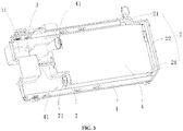
FIG. 3 is a schematic diagram showing structures of an accommodating member and a storage container of a clothing treatment agent dispensing apparatus according to the present invention; -
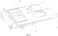
FIG. 4 is a schematic diagram showing structures of a dispensing container and a liquid delivery tube of a clothing treatment agent dispensing apparatus according to the present invention; -
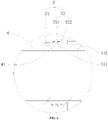
FIG. 5 is a sectional view of a clothing treatment agent dispensing apparatus according to the present invention; and -
FIG. 6 is a partial enlarged view ofFIG. 5 . - First, it should be understood by a person skilled in the art that the implementations described below are merely intended to explain the technical principles of the present invention, and are not intended to limit the protection scope of the present invention. For example, although the following implementations are explained and illustrated in connection with a washing machine, this is not limiting, and the technical solutions of the present invention are also applicable to another clothing treatment apparatus, such as an air washing apparatus, a shoe washing machine, and a washing and drying machine. Changes in such application object do not deviate from the principle and scope of the present invention.
- It should be noted that in the description of the present invention, an orientation or positional relationship indicated by the terms "left", "right", "inner", "outer" and the like is an orientation or positional relationship shown based on the accompanying drawings, is intended only to facilitate the description rather than indicating or implying that the device or element must have a specific orientation, or be constructed and operated in a specific orientation, and therefore should not be construed as a limitation to the present invention. In addition, the terms "first" and "second" are used for descriptive purposes only and are not to be construed as indicating or implying a relative importance.
- In addition, it should also be noted that in the description of the present invention, unless otherwise specified and defined, the terms "arranged", "installed", "connection" and "connected" should be understood in a broad sense, which, for example, may be understood as fixed connection, detachable connection or integral connection; may be understood as mechanical connection or electrical connection; or may be understood as direct connection, indirect connection via an intermediate medium, or communication between the interiors of two elements. The specific meanings of the above terms in the present invention can be understood in specific cases by a person skilled in the art.
- Based on the background art, it is pointed out that an accommodating box for installing a clothing treatment agent dispensing apparatus of an existing washing machine is inconvenient to clean, which leads to a problem of poor user experience. The present invention provides a washing machine designed to enable a user to clean an accommodating box more conveniently, so as to improve user experience.
- Specifically, as shown in
FIG. 1 to FIG. 3 , the washing machine of the present invention includes anaccommodating member 1 and a clothing treatment agent dispensing apparatus provided in theaccommodating member 1, the clothing treatment agent dispensing apparatus is slidably connected to theaccommodating member 1; awater channel 2 is formed between an outer wall of the clothing treatment agent dispensing apparatus and an inner wall of theaccommodating member 1; and awater outlet 3 is formed on theaccommodating member 1, and is communicated with thewater channel 2. It can be known from the background art that, in the prior art, it is necessary to take the clothing treatment agent dispensing apparatus out of theaccommodating member 1 before cleaning theaccommodating member 1, and then the clothing treatment agent dispensing apparatus is installed into theaccommodating member 1 after cleaning theaccommodating member 1. The whole process is very tedious, with poor user experience. According to the present invention, by forming awater channel 2 between the outer wall of the clothing treatment agent dispensing apparatus and the inner wall of theaccommodating member 1, it is unnecessary to take the clothing treatment agent dispensing apparatus out of theaccommodating member 1 when theaccommodating member 1 needs to be cleaned, and water can be directly injected to thewater channel 2 to clean both theaccommodating member 1 and the outer wall of the clothing treatment agent dispensing apparatus. Moreover, awater outlet 3 is formed on theaccommodating member 1, and is communicated with thewater channel 2, so that water in thewater channel 2 can be drained. Theaccommodating member 1 is an accommodating box, and the clothing treatment agent dispensing apparatus is provided in the accommodating box and slidably connected to the accommodating box. Certainly, theaccommodating member 1 may also be provided as an accommodating bucket or an accommodating box. Such adjustment and change to a specific structural form of theaccommodating member 1 do not deviate from the principle and scope of the present invention, and should be limited within the protection scope of the present invention. - It should be noted that, the clothing treatment agent may be a detergent, then the clothing treatment agent dispensing apparatus is a dispensing box for dispensing the detergent, alternatively, the clothing treatment agent may also be a conditioner, then the clothing treatment agent dispensing apparatus is a dispensing box for dispensing the conditioner, and so on. Such adjustment and change to a specific category and a specific type of the clothing treatment agent do not deviate from the principle and scope of the present invention, and should be limited within the protection scope of the present invention.
- Preferably, as shown in
FIG. 2 andFIG. 3 , thewater channel 2 includes afirst water channel 21 formed between an outer side wall of the clothing treatment agent dispensing apparatus and an inner side wall of theaccommodating member 1. Further preferably, thewater channel 2 further includes asecond water channel 22 formed between an outer rear wall of the clothing treatment agent dispensing apparatus and an inner rear wall of theaccommodating member 1. Thefirst water channel 21 is preferably communicated with thesecond water channel 22, in this case, only onewater outlet 3 is required. Certainly, thefirst water channel 21 may not be communicated with thesecond water channel 22, in this case, it is necessary to provide twowater outlets 3 connected to thefirst water channel 21 and thesecond water channel 22 respectively. - Preferably, as shown in
FIG. 1 andFIG. 3 , thewater outlet 3 is formed on abottom plate 11 of theaccommodating member 1. Thewater outlet 3 is formed on thebottom plate 11 to facilitate drainage of water from theaccommodating member 1. Further preferably, thebottom plate 11 is obliquely provided and thewater outlet 3 is located at a lower end of thebottom plate 11 to enable all water in thewater channel 2 to flow to thewater outlet 3, and avoid water remaining in thewater channel 2. - Preferably, as shown in
FIG. 2 to FIG. 4 , the clothing treatment agent dispensing apparatus includes astorage container 4, a dispensingcontainer 5 and aliquid delivery tube 6, thestorage container 4 is secured in theaccommodating member 1, the dispensingcontainer 5 is slidably connected to theaccommodating member 1, one end of theliquid delivery tube 6 is communicated with the dispensingcontainer 5, the other end of theliquid delivery tube 6 is inserted into thestorage container 4, and a length of theliquid delivery tube 6 is configured so that the other end of theliquid delivery tube 6 does not come out of thestorage container 4 when the dispensingcontainer 5 moves away from thestorage container 4. The clothing treatment agent dispensing apparatus is provided with a split structure, that is, thestorage container 4 and the dispensingcontainer 5 are provided separately, and only the dispensingcontainer 5 is slidably connected to theaccommodating member 1, so that a user only needs to pull out the dispensingcontainer 5 without pulling out thestorage container 4 when the user needs to add a clothing treatment agent, which improves user experience. In addition, the dispensingcontainer 5 is communicated with thestorage container 4 through theliquid delivery tube 6, and a right end of theliquid delivery tube 6 is inserted into thestorage container 4, so that when the dispensingcontainer 5 is pulled (as shown in the figures, the dispensingcontainer 5 moves to the left), theliquid delivery tube 6 moves with the dispensingcontainer 5, but the right end of theliquid delivery tube 6 does not come out of thestorage container 4, so that the clothing treatment agent injected into the dispensingcontainer 5 can be delivered into thestorage container 4 through theliquid delivery tube 6. The user pushes the dispensingcontainer 5 and theliquid delivery tube 6 together into theaccommodating member 1 after adding the clothing treatment agent to allow a right part of theliquid delivery tube 6 to be reinserted into thestorage container 4. - In addition, it should also be noted that as shown in
FIG. 2 andFIG. 3 , the dispensingcontainer 5 is provided with two dispensingcavities 51, one of which is a detergent dispensing cavity and the other is a conditioner dispensing cavity. Correspondingly, thestorage container 4 is provided with two storage cavities: a detergent storage cavity and a conditioner storage cavity, the detergent dispensing cavity is communicated with the detergent storage cavity through aliquid delivery tube 6, and the conditioner dispensing cavity is communicated with the conditioner storage cavity through anotherliquid delivery tube 6. Certainly, the number of the dispensingcavities 51 is not limited to the above two, for example, the number of the dispensingcavities 51 may also be one or three. Such adjustment and change to a specific number of the dispensingcavities 51 do not deviate from the principle and scope of the present invention, and should be limited within the protection scope of the present invention. - In addition, it should also be noted that the clothing treatment agent dispensing apparatus can also be provided integrally, that is, the
storage container 4 and the dispensingcontainer 5 are fixedly connected or integrated, and in this case, theliquid delivery tube 6 can be omitted. - Preferably, as shown in
FIG. 3 , thestorage container 4 is provided with aguide structure 41, and the other end of theliquid delivery tube 6 extends into thestorage container 4 through theguide structure 41. Theguide structure 41 is a guide pipe fitting 41 formed on an outer wall of thestorage container 4, and a right end of theliquid delivery tube 6 is inserted into thestorage container 4 through theguide pipe fitting 41. The guide pipe fitting 41 guides theliquid delivery tube 6 when theliquid delivery tube 6 moves with the dispensingcontainer 5. Certainly, theguide structure 41 can also be provided as a guide rib, a guide tube or another structure. Such adjustment and change to a specific structural form of theguide structure 41 do not deviate from the principle and scope of the present invention, and should be limited within the protection scope of the present invention. - Preferably, as shown in
FIG. 3 ,FIG. 5 andFIG. 6 , the clothing treatment agent dispensing apparatus further includes a sealingmember 7, the sealingmember 7 includes a main body part, and afirst sealing portion 71 and asecond sealing portion 72 formed on the main body part, thefirst sealing portion 71 is hermetically affixed to an outer wall of theliquid delivery tube 6, and the sealingmember 7 is hermetically connected to the guide pipe fitting 41 through thesecond sealing portion 72. The sealingmember 7 is a sealingring 7, and a main body part of the sealingring 7 has an inner diameter larger than an outer diameter of theliquid delivery tube 6. With such an arrangement, theliquid delivery tube 6 can be smoothly inserted into the sealingring 7. - Preferably, as shown in
FIG. 3 ,FIG. 5 andFIG. 6 , thefirst sealing portion 71 is a sealinglip 71 formed on an inner wall of the main body part of the sealingring 7. The sealinglip 71 is hermetically affixed to an outer wall of theliquid delivery tube 6, so that a clothing treatment agent in thestorage container 4 can be prevented from leaking along the outer wall of theliquid delivery tube 6, and when theliquid delivery tube 6 is pulled out, the sealinglip 71 can scrape off the clothing treatment agent adhered to the outer wall of theliquid delivery tube 6 to prevent the clothing treatment agent from leaking. Further preferably, the sealinglip 71 is obliquely provided in a direction from the dispensingcontainer 5 to thestorage container 4. With such an arrangement, theliquid delivery tube 6 can be smoothly inserted into the sealingring 7, and the sealinglip 71 can have a better sealing effect. - Preferably, as shown in
FIG. 3 ,FIG. 5 andFIG. 6 , the sealingring 7 is hermetically connected to an outer wall of the guide pipe fitting 41 through thesecond sealing portion 72. Thesecond sealing portion 72 includes at least one annular sealing rib formed on the inner wall of the main body part of the sealingring 7, at least one annular sealing groove is correspondingly provided on the outer wall of the guide pipe fitting 41, the annular sealing rib is in a one-to-one correspondence with the annular sealing groove, and the annular sealing rib is in a transition fit or interference fit with the annular sealing groove to hermetically seal thesealing ring 7 and theguide pipe fitting 41. The at least one annular sealing rib includes a firstannular sealing rib 721 and a secondannular sealing rib 722, and the at least one annular sealing groove includes a firstannular sealing groove 411 and a secondannular sealing groove 412. The firstannular sealing rib 721 is in a transition fit or interference fit with the firstannular sealing groove 411, and the secondannular sealing rib 722 is in a transition fit or interference fit with the secondannular sealing groove 412. By providing two annular sealing ribs and annular sealing grooves, a double protection effect can be provided, that is, after one set of annular sealing ribs and annular sealing grooves fails, the sealingring 7 can be hermetically connected to the guide pipe fitting 41 through another set of annular sealing ribs and annular sealing grooves. Certainly, the number of the annular sealing ribs and annular sealing grooves is not limited to the above two, for example, the number of the annular sealing ribs and annular sealing grooves may also be one or three. Such adjustment and change to a specific number of the annular sealing ribs and annular sealing grooves do not deviate from the principle and scope of the present invention, and should be limited within the protection scope of the present invention. Certainly, thesecond sealing portion 72 may also include at least one annular sealing groove formed on the inner wall of the main body part of the sealingring 7, at least one annular sealing rib is correspondingly provided on the outer wall of the guide pipe fitting 41, the annular sealing rib is in a one-to-one correspondence with the annular sealing groove, and the annular sealing rib is in a transition fit or interference fit with the annular sealing groove to hermetically seal thesealing ring 7 and theguide pipe fitting 41. - In addition, as a variation of the above embodiment, the sealing
ring 7 may also be hermetically connected to an inner wall of the guide pipe fitting 41 through thesecond sealing portion 72. In this case, thesecond sealing portion 72 includes at least one annular sealing rib or sealing groove formed on an outer wall of the main body part of the sealingring 7, at least one annular sealing groove or sealing rib is correspondingly provided on the inner wall of the guide pipe fitting 41, the annular sealing rib is in a one-to-one correspondence with the annular sealing groove, and the annular sealing rib is in a transition fit or interference fit with the annular sealing groove to hermetically seal thesealing ring 7 and theguide pipe fitting 41. - So far, the technical solutions of the present invention have been described with reference to the preferred implementations shown in the accompanying drawings. However, it easily occurs to a person skilled in the art that the protection scope of the present invention is obviously not limited to these specific implementations. A person skilled in the art may make equivalent modifications or replacements to relevant technical features without departing from the principle of the present invention, and technical solutions following these modifications or replacements will fall within the protection scope of the present invention.
Claims (19)
- A clothing treatment apparatus, comprising an accommodating member and a clothing treatment agent dispensing apparatus provided in the accommodating member, wherein the clothing treatment agent dispensing apparatus is slidably connected to the accommodating member; a water channel is formed between an outer wall of the clothing treatment agent dispensing apparatus and an inner wall of the accommodating member; and a water outlet is formed on the accommodating member, and is communicated with the water channel.
- The clothing treatment apparatus according to claim 1, wherein the water channel comprises a first water channel formed between an outer side wall of the clothing treatment agent dispensing apparatus and an inner side wall of the accommodating member.
- The clothing treatment apparatus according to claim 2, wherein the water channel further comprises a second water channel formed between an outer rear wall of the clothing treatment agent dispensing apparatus and an inner rear wall of the accommodating member.
- The clothing treatment apparatus according to claim 3, wherein the first water channel is communicated with the second water channel.
- The clothing treatment apparatus according to claim 1, wherein the water outlet is formed on a bottom plate of the accommodating member.
- The clothing treatment apparatus according to claim 5, wherein the bottom plate is obliquely provided and the water outlet is located at a lower end of the bottom plate to enable all water in the water channel to flow to the water outlet.
- The clothing treatment apparatus according to claim 1, wherein the clothing treatment agent dispensing apparatus comprises a storage container, a dispensing container and a liquid delivery tube, the storage container is secured in the accommodating member, the dispensing container is slidably connected to the accommodating member, one end of the liquid delivery tube is communicated with the dispensing container, the other end of the liquid delivery tube is inserted into the storage container, and a length of the liquid delivery tube is configured so that the other end of the liquid delivery tube does not come out of the storage container when the dispensing container moves away from the storage container.
- The clothing treatment apparatus according to claim 7, wherein the storage container is provided with a guide structure, and the other end of the liquid delivery tube is inserted through the guide structure into the storage container.
- The clothing treatment apparatus according to claim 8, wherein the clothing treatment agent dispensing apparatus further comprises a sealing member, the sealing member comprises a main body part, and a first sealing portion and a second sealing portion formed on the main body part, the first sealing portion is hermetically affixed to an outer wall of the liquid delivery tube, and the sealing member is hermetically connected to the guide structure through the second sealing portion.
- The clothing treatment apparatus according to claim 9, wherein the sealing member is a sealing ring, and a main body part of the sealing ring has an inner diameter larger than an outer diameter of the liquid delivery tube.
- The clothing treatment apparatus according to claim 10, wherein the first sealing portion is a sealing lip formed on an inner wall of the main body part of the sealing ring.
- The clothing treatment apparatus according to claim 11, wherein the sealing lip is obliquely provided in a direction from the dispensing container to the storage container.
- The clothing treatment apparatus according to claim 10, wherein the sealing ring is hermetically connected to an outer wall of the guide structure through the second sealing portion.
- The clothing treatment apparatus according to claim 13, wherein the second sealing portion comprises at least one annular sealing rib or sealing groove formed on the inner wall of the main body part of the sealing ring, at least one annular sealing groove or sealing rib is correspondingly provided on the outer wall of the guide structure, the annular sealing rib is in a one-to-one correspondence with the annular sealing groove, and the annular sealing rib is in a transition fit or interference fit with the annular sealing groove to hermetically seal the sealing ring and the guide structure.
- The clothing treatment apparatus according to claim 14, wherein the second sealing portion comprises a first annular sealing rib and a second annular sealing rib formed on the inner wall of the main body part of the sealing ring, a first annular sealing groove and a second annular sealing groove are correspondingly provided on the outer wall of the guide structure, the first annular sealing rib is in a transition fit or interference fit with the first annular sealing groove, and the second annular sealing rib is in a transition fit or interference fit with the second annular sealing groove.
- The clothing treatment apparatus according to claim 10, wherein the second sealing portion comprises at least one annular sealing rib or sealing groove formed on an outer wall of the main body part of the sealing ring, at least one annular sealing groove or sealing rib is correspondingly provided on an inner wall of the guide structure, the annular sealing rib is in a one-to-one correspondence with the annular sealing groove, and the annular sealing rib is in a transition fit or interference fit with the annular sealing groove to hermetically seal the sealing ring and the guide structure.
- The clothing treatment apparatus according to claim 8, wherein the guide structure is a guide pipe fitting formed on an outer wall of the storage container.
- The clothing treatment apparatus according to any one of claims 1 to 17, wherein the accommodating member is an accommodating box.
- The clothing treatment apparatus according to any one of claims 1 to 17, wherein the clothing treatment apparatus is a washing machine, and the clothing treatment agent dispensing apparatus is a dispensing box for dispensing a detergent or a condi ti oner.
Applications Claiming Priority (2)
| Application Number | Priority Date | Filing Date | Title |
|---|---|---|---|
| CN201910555556.XA CN112127116B (en) | 2019-06-25 | 2019-06-25 | Clothes treating apparatus |
| PCT/CN2020/095738 WO2020259314A1 (en) | 2019-06-25 | 2020-06-12 | Clothing treatment apparatus |
Publications (4)
| Publication Number | Publication Date |
|---|---|
| EP3992349A1 true EP3992349A1 (en) | 2022-05-04 |
| EP3992349A4 EP3992349A4 (en) | 2023-03-15 |
| EP3992349C0 EP3992349C0 (en) | 2025-11-19 |
| EP3992349B1 EP3992349B1 (en) | 2025-11-19 |
Family
ID=73850002
Family Applications (1)
| Application Number | Title | Priority Date | Filing Date |
|---|---|---|---|
| EP20833419.3A Active EP3992349B1 (en) | 2019-06-25 | 2020-06-12 | Clothing treatment apparatus |
Country Status (3)
| Country | Link |
|---|---|
| EP (1) | EP3992349B1 (en) |
| CN (1) | CN112127116B (en) |
| WO (1) | WO2020259314A1 (en) |
Family Cites Families (22)
| Publication number | Priority date | Publication date | Assignee | Title |
|---|---|---|---|---|
| US3975931A (en) * | 1972-10-26 | 1976-08-24 | Siemens Electrogerate Gmbh | Flush-in device for an appliance such as a laundry or dishwashing machine |
| DE3403622A1 (en) * | 1984-02-02 | 1985-08-14 | Bosch-Siemens Hausgeräte GmbH, 7000 Stuttgart | Automatically controlled washing machine |
| JPH08238396A (en) * | 1995-03-06 | 1996-09-17 | Toshiba Corp | Detergent loading device for washing machine |
| KR101064702B1 (en) * | 2004-02-06 | 2011-09-14 | 엘지전자 주식회사 | Detergent Supply Device of Washing Machine |
| JP2006014752A (en) * | 2004-06-30 | 2006-01-19 | Hitachi Home & Life Solutions Inc | Fully automatic washing machine |
| EP2251480B1 (en) * | 2009-05-11 | 2017-11-29 | Electrolux Home Products Corporation N.V. | Laundry washing appliance |
| KR101757740B1 (en) * | 2011-01-12 | 2017-07-27 | 삼성전자주식회사 | Detergent case and washing machine having the same |
| CN202023090U (en) * | 2011-04-07 | 2011-11-02 | 合肥荣事达三洋电器股份有限公司 | Water inlet device of instant washing powder box |
| EP2554738B1 (en) * | 2011-08-01 | 2018-04-18 | Electrolux Home Products Corporation N.V. | Laundry washing machine |
| CN104674511B (en) * | 2013-11-27 | 2017-08-22 | 无锡小天鹅股份有限公司 | For the detergent throwing mechanism of washing machine and the washing machine with it |
| CN204039770U (en) * | 2014-08-15 | 2014-12-24 | 松下家电研究开发(杭州)有限公司 | Detergent dissolving and foaming device and washing machine |
| CN204589638U (en) * | 2014-12-10 | 2015-08-26 | 合肥市宏键精工模具有限责任公司 | A kind of roller washing machine water inflowing box assembly |
| CN105970560B (en) * | 2016-06-30 | 2018-06-19 | 无锡小天鹅股份有限公司 | Sealing ring, washing launch component and with its roller washing machines |
| WO2018040761A1 (en) * | 2016-08-31 | 2018-03-08 | 无锡小天鹅股份有限公司 | Detergent dispensing device of washing machine and washing machine having same |
| CN108252032A (en) * | 2016-12-28 | 2018-07-06 | 青岛海尔滚筒洗衣机有限公司 | A kind of detergent throwing device, the washing machine and its control method with the device |
| CN108315964B (en) * | 2017-01-16 | 2020-06-26 | 青岛海尔滚筒洗衣机有限公司 | A water inlet box assembly and washing machine |
| CN206887518U (en) * | 2017-05-23 | 2018-01-16 | 无锡小天鹅股份有限公司 | The delivery device and washing machine of washing machine |
| CN107354679B (en) * | 2017-08-21 | 2019-12-17 | 无锡小天鹅电器有限公司 | Distributor box assembly, detergent feeding device and washing machine |
| CN107974807A (en) * | 2017-12-11 | 2018-05-01 | 青岛海尔洗衣机有限公司 | Laundry treatment agents for clothes treatment device launch component and clothes treatment device |
| CN207760579U (en) * | 2017-12-11 | 2018-08-24 | 青岛海尔洗衣机有限公司 | Laundry treatment agents for clothes treatment device launch component and clothes treatment device |
| CN109898288A (en) * | 2017-12-11 | 2019-06-18 | 青岛海尔洗衣机有限公司 | Laundry treatment agents for clothes treatment device launch component and clothes treatment device |
| CN208266487U (en) * | 2018-04-20 | 2018-12-21 | 青岛海尔滚筒洗衣机有限公司 | Laundry treatment agents for clothes treatment device launch component and clothes treatment device |
-
2019
- 2019-06-25 CN CN201910555556.XA patent/CN112127116B/en active Active
-
2020
- 2020-06-12 WO PCT/CN2020/095738 patent/WO2020259314A1/en not_active Ceased
- 2020-06-12 EP EP20833419.3A patent/EP3992349B1/en active Active
Also Published As
| Publication number | Publication date |
|---|---|
| EP3992349A4 (en) | 2023-03-15 |
| CN112127116A (en) | 2020-12-25 |
| EP3992349C0 (en) | 2025-11-19 |
| WO2020259314A1 (en) | 2020-12-30 |
| EP3992349B1 (en) | 2025-11-19 |
| CN112127116B (en) | 2023-06-20 |
Similar Documents
| Publication | Publication Date | Title |
|---|---|---|
| KR102048858B1 (en) | Washing machine without water and control method | |
| CN205529555U (en) | Can dismantle washing machine device of water course | |
| EP3670733A1 (en) | Washing machine having detergent supply device | |
| EP3992349B1 (en) | Clothing treatment apparatus | |
| CN110359237B (en) | Clothes treatment agent box structure and washing machine | |
| CN105063954A (en) | Twin-tub washer | |
| CN116616672A (en) | shoe washing machine | |
| CN112227019B (en) | Liquid outlet structure, washing additive box and washing machine | |
| WO2022021749A1 (en) | Detergent box and laundry processing device | |
| CN110195332A (en) | A kind of water guide sleeve and washing machine free of cleaning | |
| EP3992348A1 (en) | Laundry treatment agent dispensing assembly for use in laundry treatment device, and laundry treatment device | |
| CN111920358B (en) | Container apparatus | |
| CN114250597A (en) | Upper water drainage laundry equipment | |
| CN110387689B (en) | Clothes treating agent feeding component for clothes treating equipment and clothes treating equipment | |
| CN221285644U (en) | Drainage structure and floor brush | |
| CN210104343U (en) | Clothes treating apparatus | |
| CN112127117B (en) | A clothing processing agent input subassembly and clothing processing apparatus for clothing processing apparatus | |
| JP2021530257A (en) | Clothes processing agent input material for garment processing equipment and garment processing equipment | |
| CN217869598U (en) | Drawer type washing device and washing equipment | |
| CN223150861U (en) | Clothes treatment device | |
| CN114687158B (en) | Spray system and clothes treatment equipment | |
| EP3783141A1 (en) | Clothing treatment agent dispensing assembly for use in clothing treatment device, and clothing treatment device | |
| EP4656789A1 (en) | Detergent dispenser for washing machine and washing machine comprising same | |
| CN221460750U (en) | washing machine | |
| CN220579615U (en) | A cleaning structure and clothing processing equipment |
Legal Events
| Date | Code | Title | Description |
|---|---|---|---|
| STAA | Information on the status of an ep patent application or granted ep patent |
Free format text: STATUS: THE INTERNATIONAL PUBLICATION HAS BEEN MADE |
|
| PUAI | Public reference made under article 153(3) epc to a published international application that has entered the european phase |
Free format text: ORIGINAL CODE: 0009012 |
|
| STAA | Information on the status of an ep patent application or granted ep patent |
Free format text: STATUS: REQUEST FOR EXAMINATION WAS MADE |
|
| 17P | Request for examination filed |
Effective date: 20220123 |
|
| AK | Designated contracting states |
Kind code of ref document: A1 Designated state(s): AL AT BE BG CH CY CZ DE DK EE ES FI FR GB GR HR HU IE IS IT LI LT LU LV MC MK MT NL NO PL PT RO RS SE SI SK SM TR |
|
| DAV | Request for validation of the european patent (deleted) | ||
| DAX | Request for extension of the european patent (deleted) | ||
| A4 | Supplementary search report drawn up and despatched |
Effective date: 20230214 |
|
| RIC1 | Information provided on ipc code assigned before grant |
Ipc: D06F 39/02 20060101AFI20230208BHEP |
|
| GRAP | Despatch of communication of intention to grant a patent |
Free format text: ORIGINAL CODE: EPIDOSNIGR1 |
|
| STAA | Information on the status of an ep patent application or granted ep patent |
Free format text: STATUS: GRANT OF PATENT IS INTENDED |
|
| INTG | Intention to grant announced |
Effective date: 20250324 |
|
| GRAS | Grant fee paid |
Free format text: ORIGINAL CODE: EPIDOSNIGR3 |
|
| GRAA | (expected) grant |
Free format text: ORIGINAL CODE: 0009210 |
|
| STAA | Information on the status of an ep patent application or granted ep patent |
Free format text: STATUS: THE PATENT HAS BEEN GRANTED |
|
| AK | Designated contracting states |
Kind code of ref document: B1 Designated state(s): AL AT BE BG CH CY CZ DE DK EE ES FI FR GB GR HR HU IE IS IT LI LT LU LV MC MK MT NL NO PL PT RO RS SE SI SK SM TR |
|
| REG | Reference to a national code |
Ref country code: CH Ref legal event code: F10 Free format text: ST27 STATUS EVENT CODE: U-0-0-F10-F00 (AS PROVIDED BY THE NATIONAL OFFICE) Effective date: 20251119 Ref country code: GB Ref legal event code: FG4D |
|
| REG | Reference to a national code |
Ref country code: IE Ref legal event code: FG4D |
|
| U01 | Request for unitary effect filed |
Effective date: 20251202 |
|
| U07 | Unitary effect registered |
Designated state(s): AT BE BG DE DK EE FI FR IT LT LU LV MT NL PT RO SE SI Effective date: 20251209 |
|
| PG25 | Lapsed in a contracting state [announced via postgrant information from national office to epo] |
Ref country code: ES Free format text: LAPSE BECAUSE OF FAILURE TO SUBMIT A TRANSLATION OF THE DESCRIPTION OR TO PAY THE FEE WITHIN THE PRESCRIBED TIME-LIMIT Effective date: 20251119 |
|
| PG25 | Lapsed in a contracting state [announced via postgrant information from national office to epo] |
Ref country code: NO Free format text: LAPSE BECAUSE OF FAILURE TO SUBMIT A TRANSLATION OF THE DESCRIPTION OR TO PAY THE FEE WITHIN THE PRESCRIBED TIME-LIMIT Effective date: 20260219 |
|
| PG25 | Lapsed in a contracting state [announced via postgrant information from national office to epo] |
Ref country code: HR Free format text: LAPSE BECAUSE OF FAILURE TO SUBMIT A TRANSLATION OF THE DESCRIPTION OR TO PAY THE FEE WITHIN THE PRESCRIBED TIME-LIMIT Effective date: 20251119 |
|
| PG25 | Lapsed in a contracting state [announced via postgrant information from national office to epo] |
Ref country code: RS Free format text: LAPSE BECAUSE OF FAILURE TO SUBMIT A TRANSLATION OF THE DESCRIPTION OR TO PAY THE FEE WITHIN THE PRESCRIBED TIME-LIMIT Effective date: 20260219 |
|
| PG25 | Lapsed in a contracting state [announced via postgrant information from national office to epo] |
Ref country code: IS Free format text: LAPSE BECAUSE OF FAILURE TO SUBMIT A TRANSLATION OF THE DESCRIPTION OR TO PAY THE FEE WITHIN THE PRESCRIBED TIME-LIMIT Effective date: 20260319 |
|
| PG25 | Lapsed in a contracting state [announced via postgrant information from national office to epo] |
Ref country code: PL Free format text: LAPSE BECAUSE OF FAILURE TO SUBMIT A TRANSLATION OF THE DESCRIPTION OR TO PAY THE FEE WITHIN THE PRESCRIBED TIME-LIMIT Effective date: 20251119 |
|
| PG25 | Lapsed in a contracting state [announced via postgrant information from national office to epo] |
Ref country code: SM Free format text: LAPSE BECAUSE OF FAILURE TO SUBMIT A TRANSLATION OF THE DESCRIPTION OR TO PAY THE FEE WITHIN THE PRESCRIBED TIME-LIMIT Effective date: 20251119 |
|
| PG25 | Lapsed in a contracting state [announced via postgrant information from national office to epo] |
Ref country code: CZ Free format text: LAPSE BECAUSE OF FAILURE TO SUBMIT A TRANSLATION OF THE DESCRIPTION OR TO PAY THE FEE WITHIN THE PRESCRIBED TIME-LIMIT Effective date: 20251119 |
|
| PG25 | Lapsed in a contracting state [announced via postgrant information from national office to epo] |
Ref country code: SK Free format text: LAPSE BECAUSE OF FAILURE TO SUBMIT A TRANSLATION OF THE DESCRIPTION OR TO PAY THE FEE WITHIN THE PRESCRIBED TIME-LIMIT Effective date: 20251119 |
|
| U20 | Renewal fee for the european patent with unitary effect paid |
Year of fee payment: 7 Effective date: 20260629 |