EP3992346A1 - Front-loading washing machine - Google Patents
Front-loading washing machine Download PDFInfo
- Publication number
- EP3992346A1 EP3992346A1 EP20832111.7A EP20832111A EP3992346A1 EP 3992346 A1 EP3992346 A1 EP 3992346A1 EP 20832111 A EP20832111 A EP 20832111A EP 3992346 A1 EP3992346 A1 EP 3992346A1
- Authority
- EP
- European Patent Office
- Prior art keywords
- inner drum
- door
- drum
- washing machine
- magnetic element
- Prior art date
- Legal status (The legal status is an assumption and is not a legal conclusion. Google has not performed a legal analysis and makes no representation as to the accuracy of the status listed.)
- Withdrawn
Links
- 238000005406 washing Methods 0.000 title claims abstract description 183
- 238000001514 detection method Methods 0.000 claims abstract description 74
- 230000007246 mechanism Effects 0.000 claims description 60
- 235000014676 Phragmites communis Nutrition 0.000 claims description 19
- 230000006698 induction Effects 0.000 claims description 11
- 239000002184 metal Substances 0.000 claims description 7
- 229910052751 metal Inorganic materials 0.000 claims description 7
- 230000006835 compression Effects 0.000 claims description 5
- 238000007906 compression Methods 0.000 claims description 5
- XLYOFNOQVPJJNP-UHFFFAOYSA-N water Substances O XLYOFNOQVPJJNP-UHFFFAOYSA-N 0.000 description 212
- 238000010586 diagram Methods 0.000 description 25
- 238000000034 method Methods 0.000 description 8
- 238000007789 sealing Methods 0.000 description 8
- 230000000694 effects Effects 0.000 description 7
- 239000003599 detergent Substances 0.000 description 6
- 230000005389 magnetism Effects 0.000 description 6
- 230000008569 process Effects 0.000 description 5
- XEEYBQQBJWHFJM-UHFFFAOYSA-N Iron Chemical compound [Fe] XEEYBQQBJWHFJM-UHFFFAOYSA-N 0.000 description 4
- PXHVJJICTQNCMI-UHFFFAOYSA-N Nickel Chemical compound [Ni] PXHVJJICTQNCMI-UHFFFAOYSA-N 0.000 description 4
- 239000008399 tap water Substances 0.000 description 4
- 235000020679 tap water Nutrition 0.000 description 4
- 230000005540 biological transmission Effects 0.000 description 3
- 238000010438 heat treatment Methods 0.000 description 3
- 238000012986 modification Methods 0.000 description 3
- 230000004048 modification Effects 0.000 description 3
- 230000002093 peripheral effect Effects 0.000 description 3
- 230000009471 action Effects 0.000 description 2
- 229910017052 cobalt Inorganic materials 0.000 description 2
- 239000010941 cobalt Substances 0.000 description 2
- GUTLYIVDDKVIGB-UHFFFAOYSA-N cobalt atom Chemical compound [Co] GUTLYIVDDKVIGB-UHFFFAOYSA-N 0.000 description 2
- 230000001276 controlling effect Effects 0.000 description 2
- 230000007547 defect Effects 0.000 description 2
- 238000009434 installation Methods 0.000 description 2
- 229910052742 iron Inorganic materials 0.000 description 2
- 239000007788 liquid Substances 0.000 description 2
- 239000000696 magnetic material Substances 0.000 description 2
- 229910052759 nickel Inorganic materials 0.000 description 2
- 230000001846 repelling effect Effects 0.000 description 2
- 230000009286 beneficial effect Effects 0.000 description 1
- 238000007599 discharging Methods 0.000 description 1
- 230000005484 gravity Effects 0.000 description 1
- 230000036541 health Effects 0.000 description 1
- 238000005259 measurement Methods 0.000 description 1
- 239000011148 porous material Substances 0.000 description 1
- 230000001105 regulatory effect Effects 0.000 description 1
- 239000008237 rinsing water Substances 0.000 description 1
- 239000000523 sample Substances 0.000 description 1
- 230000035945 sensitivity Effects 0.000 description 1
- 238000005303 weighing Methods 0.000 description 1
Images







Classifications
-
- D—TEXTILES; PAPER
- D06—TREATMENT OF TEXTILES OR THE LIKE; LAUNDERING; FLEXIBLE MATERIALS NOT OTHERWISE PROVIDED FOR
- D06F—LAUNDERING, DRYING, IRONING, PRESSING OR FOLDING TEXTILE ARTICLES
- D06F37/00—Details specific to washing machines covered by groups D06F21/00 - D06F25/00
- D06F37/02—Rotary receptacles, e.g. drums
- D06F37/04—Rotary receptacles, e.g. drums adapted for rotation or oscillation about a horizontal or inclined axis
- D06F37/10—Doors; Securing means therefor
-
- D—TEXTILES; PAPER
- D06—TREATMENT OF TEXTILES OR THE LIKE; LAUNDERING; FLEXIBLE MATERIALS NOT OTHERWISE PROVIDED FOR
- D06F—LAUNDERING, DRYING, IRONING, PRESSING OR FOLDING TEXTILE ARTICLES
- D06F23/00—Washing machines with receptacles, e.g. perforated, having a rotary movement, e.g. oscillatory movement, the receptacle serving both for washing and for centrifugally separating water from the laundry
- D06F23/02—Washing machines with receptacles, e.g. perforated, having a rotary movement, e.g. oscillatory movement, the receptacle serving both for washing and for centrifugally separating water from the laundry and rotating or oscillating about a horizontal axis
- D06F23/025—Washing machines with receptacles, e.g. perforated, having a rotary movement, e.g. oscillatory movement, the receptacle serving both for washing and for centrifugally separating water from the laundry and rotating or oscillating about a horizontal axis with a rotatable imperforate tub
-
- D—TEXTILES; PAPER
- D06—TREATMENT OF TEXTILES OR THE LIKE; LAUNDERING; FLEXIBLE MATERIALS NOT OTHERWISE PROVIDED FOR
- D06F—LAUNDERING, DRYING, IRONING, PRESSING OR FOLDING TEXTILE ARTICLES
- D06F34/00—Details of control systems for washing machines, washer-dryers or laundry dryers
- D06F34/14—Arrangements for detecting or measuring specific parameters
- D06F34/20—Parameters relating to constructional components, e.g. door sensors
-
- D—TEXTILES; PAPER
- D06—TREATMENT OF TEXTILES OR THE LIKE; LAUNDERING; FLEXIBLE MATERIALS NOT OTHERWISE PROVIDED FOR
- D06F—LAUNDERING, DRYING, IRONING, PRESSING OR FOLDING TEXTILE ARTICLES
- D06F2103/00—Parameters monitored or detected for the control of domestic laundry washing machines, washer-dryers or laundry dryers
- D06F2103/16—Washing liquid temperature
-
- D—TEXTILES; PAPER
- D06—TREATMENT OF TEXTILES OR THE LIKE; LAUNDERING; FLEXIBLE MATERIALS NOT OTHERWISE PROVIDED FOR
- D06F—LAUNDERING, DRYING, IRONING, PRESSING OR FOLDING TEXTILE ARTICLES
- D06F2103/00—Parameters monitored or detected for the control of domestic laundry washing machines, washer-dryers or laundry dryers
- D06F2103/18—Washing liquid level
-
- D—TEXTILES; PAPER
- D06—TREATMENT OF TEXTILES OR THE LIKE; LAUNDERING; FLEXIBLE MATERIALS NOT OTHERWISE PROVIDED FOR
- D06F—LAUNDERING, DRYING, IRONING, PRESSING OR FOLDING TEXTILE ARTICLES
- D06F34/00—Details of control systems for washing machines, washer-dryers or laundry dryers
- D06F34/14—Arrangements for detecting or measuring specific parameters
Definitions
- the invention belongs to the technical field of washing machine, and particularly relates to a drum washing machine.
- the washing machine helps people get rid of the trouble of washing laundry and brings great convenience to people.
- the washing machine has certain defects such as taking long time and using large water.
- the water resource is becoming more and more important as an important natural resource, and the water saving awareness of people is improved.
- an inner drum structure without holes is adopted.
- the biggest problem of the inner drum structure without holes is in a problem to close in seal an inner drum door.
- the inner drum door Due to negligence of a user, the inner drum door is not locked in place, but a position detection device does not detect the above situation to cause water leakage under the conditions of washing or rinsing and dewatering, and a door body is not locked in place and rotation at a high speed to cause damage and the like occur.
- the technical problem to be solved by the invention is to overcome the defects in the prior art, and the invention provides a drum washing machine capable of accurately judging whether the inner drum door is locked or not.
- a drum washing machine includes: an inner drum with an inner drum opening; an inner drum door, mounted at the inner drum opening in an opened and closed manner; a position detection device, configured to detect whether the inner drum door is locked or not; and a door closing hindering device, configured to apply force on the inner drum door for hindering being closed.
- the door closing hindering device is arranged on the inner drum; or the door closing hindering device is arranged on the inner drum door; or, the door closing hindering device is arranged between the inner drum and the inner drum door.
- the door closing hindering device is an elastic piece arranged between the inner drum and the inner drum door, and two elastic ends of the elastic piece abut against the inner drum and the inner drum door.
- the inner drum door is connected to the inner drum opening through an inner drum door shaft.
- the elastic piece is a torsional spring arranged on the inner drum door shaft in a sleeving mode.
- the torsional spring includes a torsional spring body in a spiral shape, the torsional spring body is arranged on the inner drum door shaft in a sleeving mode, and two end parts of the torsion spring body extend outwards and respectively abut against the inner drum and the inner drum door.
- the door closing hindering device is a hydraulic telescopic rod, an gas pressure telescopic rod or a compression spring.
- the position detection device includes: a detected terminal arranged on the inner drum door; and a position sensor arranged correspondingly to the detected terminal and provided with a sensing area capable of sensing the detected terminal.
- the drum washing machine further includes an outer drum which is arranged outside the inner drum in a sleeving mode and is coaxial with the inner drum, and the position sensor is arranged on the outer drum and corresponds to the position of the detected terminal.
- the drum washing machine further includes a shell arranged outside the inner drum, and the position sensor is arranged on the shell and corresponds to the position of the detected terminal.
- the inner drum door is locked on the inner drum through a locking mechanism.
- the locking mechanism includes a locking piece arranged on the inner drum door and a locking groove arranged in the inner drum corresponding to the locking piece.
- the detected terminal is arranged on the locking piece.
- the position detection device is an electromagnetic type sensor, the position sensor is an electromagnetic sensor, and the detected terminal is a permanent magnet rotor;
- the door closing hindering device includes a magnetic element which is able to attract and repel the inner drum door, and applies force on the inner drum door for hindering being closed.
- the magnetic element includes a first magnetic element arranged on the inner drum door and a second magnetic element correspondingly arranged at the inner drum opening, and the first magnetic element and the second magnetic element repel each other.
- same magnetic poles of the first magnetic element and the second magnetic element face with each other.
- both the first magnetic element and the second magnetic element are permanent magnets.
- the drum washing machine further includes a shell arranged outside the inner drum.
- the magnetic element includes a first magnetic element arranged on the inner drum door and a second magnetic element correspondingly arranged on the shell, and the first magnetic element and the second magnetic element attract each other.
- the drum washing machine further includes a shell arranged outside the inner drum, a machine door is arranged at the position, corresponding to the inner drum door, of the shell, and the magnetic element includes a first magnetic element arranged on the inner drum door and a second magnetic element correspondingly arranged on the machine door, and the first magnetic element and the second magnetic element attract each other.
- the first magnetic element is a magnetic induction piece or a permanent magnet arranged on the inner drum door
- the second magnetic element is an electromagnetic module arranged correspondingly.
- anisotropic magnetic poles of the first magnetic element and the second magnetic element face with each other.
- both the first magnetic element and the second magnetic element are permanent magnets.
- the first magnetic element is a magnetic induction piece
- the second magnetic element is a permanent magnet
- the first magnetic element is a permanent magnet
- the second magnetic element is a magnetic induction piece.
- the position detection device includes: a detected terminal arranged on the inner drum door; and a position sensor arranged correspondingly to the detected terminal and provided with a sensing area capable of sensing the detected terminal.
- the position sensor is a reed switch sensor.
- the drum washing machine further includes an outer drum which is arranged outside the inner drum in a sleeving mode and coaxial with the inner drum, and the position sensor is correspondingly arranged on the outer drum and corresponds to the position of the detected terminal.
- the drum washing machine further includes a shell arranged outside the inner drum, and the position sensor is correspondingly arranged on the shell and corresponds to the position of the detected terminal.
- the inner drum door is locked on the inner drum through a locking mechanism.
- the locking mechanism includes a locking piece arranged on the inner drum door and a locking groove arranged in the inner drum corresponding to the locking piece, and the detected terminal is arranged on the locking piece.
- the invention has the following beneficial effects.
- the door closing hindering device when the inner drum door is closed, the force on the inner drum door for hindering being closed is generated. If the inner drum door is not locked, the inner drum door is opened by a certain angle, so that the detected terminal on the inner drum door is not in the sensing range of the position sensor, and the probability of misjudgment of the position detection device is reduced.
- the problems in the prior art is avoided, such as the inner drum door is unlocked, but the inner drum door is still closed at the inner drum opening or the opening angle is very small, so that the position detection device misjudges that the inner drum door is locked, thereby after the washing machine is started, the inner drum rotates at a high speed to cause safety accidents.
- fixing knot 35. locking mechanism; 38. detected terminal; 39. locking groove; 40. locking rod; 41. locking motor; 42. outer drum rear wall; 43. lifting rib; 46. inner drum door pushing and closing device; 52. locking piece; 53. locking groove; 54. sensing area; 55. door closing hindering device; 56. inner drum door shaft; 57. machine door shaft; 61. first magnetic element; 62. second magnetic element.
- a drum washing machine which is provided with an inner drum without holes and is of a front-open structure is provided by the embodiment.
- the drum washing machine is simple in structure, and washing/rinsing water does not need to be between the inner drum and the outer drum, so that the washing water used in the washing machine is greatly reduced.
- the possibility of dirt adhesion between the inner drum and the outer drum is avoided.
- the user health and the user experience are greatly improved, and water resources are greatly saved.
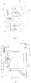
- the drum washing machine of the embodiment is provided with a shell 19.
- the shell 19 includes an upper deck plate 2, a front plate, a rear back plate and a bottom plate. Bottom feet 9 are fixedly installed on the bottom plate and used for supporting the whole washing machine.
- An outer drum 18 is arranged in the shell 19, and an inner drum 17 is coaxially arranged in the outer drum 18.
- the outer drum 18 is mainly used for collecting water drained out of the inner drum 17 and water drained out of the inner drum 17 in high-speed centrifugal dewatering process.
- the inner drum rotates, and preferably, lifting ribs 43 are arranged, so that the laundry are continuously lifted, dropped and beaten cleaned.
- the inner drum 17 is of a structure without holes.
- the outer drum 18 is provided with a central mounting hole for mounting and fixing a bearing 12.
- An inner drum shaft 13 fixedly connected with the inner drum 17 penetrates through the bearing 12 and is connected with a driving motor 16.
- An inner drum door 6 capable of being opened/closed is installed on a drum opening in the front portion of the inner drum 17, and therefore the inner drum 17 is of a sealed cabin structure.
- a machine door 5 capable of being opened/closed is installed on the shell 19.
- the embodiment of the invention mainly solves the problem of how to accurately determine the water inflow of the drum washing machine with aN inner drum without holes, and the specific solution is as follows.
- the drum washing machine includes an inner drum 17 and a water inlet pipeline communicating with the inner drum 17.
- the inner drum 17 is a drum without holes and contains washing water when laundry are washed.
- a flow sensor 1 used for detecting water inflow is arranged on the water inlet pipeline.
- the flow sensor 1 is arranged on the water inlet pipeline to monitor the water inflow.
- a water inlet valve 20 is closed, and water feeding is completed.
- the flow sensor is adopted to solve the water feeding problem of the drum washing machine having the inner drum without holes according to the set water level, the washing effect is ensured, the structure is simple, and control is convenient.
- the drum washing machine of the embodiment includes a water inlet valve 20 and a detergent box 3.
- the water inlet pipeline includes a first water inlet pipe and a second water inlet pipe, the outlet end of the water inlet valve 20 is communicated with the detergent box 3 through the first water inlet pipe, and the outlet end of the detergent box 3 is communicated with the inner drum 17 through the second water inlet pipe.
- the flow sensor 1 is arranged on the first water inlet pipe or the second water inlet pipe.
- the flow sensor 1 is arranged on the first water inlet pipe, so that the detergent in the detergent box can be prevented from entering the flow sensor 1.
- the drum washing machine of the embodiment includes a master controller 4, and the flow sensor 1 is electrically connected with the master controller 4 through a circuit.
- the master controller 4 can collect the water inflow of the inner drum 17 in real time, and the water inlet valve 20 is closed when the set water inflow is reached.
- the flow sensor 1 is a rotor flow sensor, or a turbine flow sensor, or an ultrasonic flow sensor, or an electromagnetic flow sensor, or a pore plate flow sensor.
- the flow sensor 1 can be arranged at any position of the water inlet pipeline.
- the flow sensor 1 is arranged behind the water inlet valve 20 to accurately meter the flow of water entering the sealed inner drum 17.
- the flow sensor 1 is connected with the master controller 4 through a circuit, and the master controller 4 can collect the water inflow of the inner drum 17 in real time, so that the water inlet valve 20 is closed when the set water inflow is reached.
- the drum washing machine of the embodiment includes a driving motor 16 and an inner drum shaft 13, and the driving motor 16 is in transmission connection with the inner drum 17 through the inner drum shaft 13 to drive the inner drum 17 to rotate.
- a hollow channel 14 communicating with the interior of the inner drum 17 is formed in the inner drum shaft 13, and the water inlet pipeline is communicated with the hollow channel of the inner drum shaft 13.
- the inner drum shaft 13 is connected with the driving motor 16.
- the driving motor 16 includes a stator and a rotor, and the rotor is fixedly connected with the inner drum shaft 13.
- a through hole is formed in the center of the rotor, and the water inlet pipeline penetrates through the through hole of the rotor to be communicated with the hollow channel 14 of the inner drum shaft 13.
- first dynamic sealing structure 15 is arranged between the water inlet pipeline and the through hole of the rotor, and a second sealing structure is arranged between the through hole of the rotor and the hollow channel 14 of the inner drum shaft 13.
- the drum washing machine of the embodiment includes an outer drum 18.
- An inner drum drainage hole is formed in the side wall of the inner drum 17, a one-way valve plug 11 which is normally closed is installed in the inner drum drainage hole, and a pushing rod mechanism 10 used for ejecting the one-way valve plug 11 open for drainage is installed on the outer drum 18.
- the outer drum 18 is further provided with a locking mechanism used for stopping rotation of the inner drum 17.After the locking mechanism locks the inner drum, the pushing rod mechanism 10 ejects the one-way valve plug 11 open for drainage.
- a plurality of dewatering holes are formed in the side wall of the inner drum 17, and centrifugal valves are installed on the dewatering holes.
- the centrifugal valves are opened under the action of dewatering centrifugal force to conduct dewatering and drainage.
- the embodiment of the invention also provides a control method of the drum washing machine.
- the washing machine executes a washing/rinsing program.
- the flow sensor detects the water inflow value in real time
- the washing machine calculates the water inflow according to the water inflow value and the water feeding time
- water feeding is stopped when the water inflow reaches the set water inflow of the washing machine.
- the drum washing machine is provided with a plurality of water inflow values which can be selected by a user, and water is fed into the washing machine according to the water inflow value selected by the user.
- the drum washing machine has a laundry weighing function, and water can be fed after determining the water inflow value according to the weight of laundry.
- the drum washing machine includes an inner drum 17 and a water inlet pipeline.
- the inner drum is an inner drum without holes and contains washing water when laundry are washed.
- the drum washing machine further includes a water measuring device used for measuring the water inflow, the water inlet pipeline is communicated with the water measuring device, and the water measuring device is communicated with the inner drum.
- the water measuring device of the drum washing machine of the embodiment water enters the water measuring device for quantitative measurement before entering the inner drum 1.
- the water measuring frequency of the water measuring device is determined according to the set water level, and therefore the problem that water enters the drum washing machine having the inner drum without holes according to the set water level is solved, the washing effect is good, the structure is simple, and it is convenient to be controlled.
- the water measuring device includes a water measuring tank 21, and the water measuring tank 21 is provided with a water inlet and a water outlet.
- the water inlet is communicated with a water inlet pipeline, and the water outlet is communicated with the inner drum 17.
- the water outlet is provided with a water outlet control device which is used for controlling the water outlet to be opened when the water amount in the water measuring tank 21 reaches a set value.
- the water measuring tank 21 is arranged at the bottom of the inner drum 17.
- the water measuring device includes a water level detection device 22 used for detecting the water level in the water measuring tank 21.
- the water outlet control device is a water tank drainage pump 23. When it is detected by the water level detection device 22 that the water level in the water measuring tank 21 reaches a set value, the water tank drainage pump 23 is started to pump water in the water measuring tank 21 into the inner drum 17.
- the water measuring tank 21 is arranged above the inner drum 17.
- the water measuring device includes a water level detection device 22 used for detecting the water level in the water measuring water tank.
- the water outlet control device is a water tank drain valve 25.
- the water tank drain valve 25 is opened to drain water in the water measuring tank 21 into the inner drum when it is detected by the water level detection device 22 that the water level in the water measuring tank 21 reaches a set value.
- the water level detection device 22 of the embodiment is a liquid level sensor.
- the liquid level sensor includes an gas chamber and a sensor unit, and the gas chamber is communicated with the water measuring tank.
- the water level detection device 22 includes a plurality of water level detection probes which are arranged in the water measuring tank in the depth direction of the water measuring tank.
- the water measuring tank 21 is arranged above the inner drum 17.
- the water outlet is formed in the bottom wall of the water measuring tank 21.
- the water outlet control device is a water tank one-way valve for keeping the water outlet normally closed. When the water amount in the water measuring tank reaches a certain value, the water tank one-way valve is opened under the water pressure gravity. After water in the water measuring tank 21 is discharged into the inner drum 17, the water tank one-way valve resets to keep the water outlet closed.
- An overflow hole 24 is formed in the water measuring tank 21 of the embodiment, and the overflow hole 24 is connected with an overflow pipeline used for guiding out water overflowing out of the water measuring tank.
- the drum washing machine includes a drainage pipeline 8, and the overflow pipeline is communicated with the drainage pipeline 8.
- the water measuring device includes a heating device 26 arranged in the water measuring tank 21 and a water temperature detection device for detecting the water temperature in the water measuring tank.
- the embodiment of the invention also provides a control method of the drum washing machine.
- the drum washing machine controls the washing water to enter the water measuring tank in executing a washing program or a rinsing program.
- the water feeding is stopped, the water in the water measuring tank is completely discharged into the inner drum.
- the drum washing machine is restarted to feed water into the water measuring tank, and the above process is circulated until the water level in the inner drum reaches a set value, and water feeding is ended.
- the drum washing machine controls the washing water to enter the water measuring tank.
- the heating device is controlled to operate to heat the washing water.
- the water temperature detection device that the water temperature in the water measuring tank reaches the set value, the water in the water measuring tank is completely discharged into the inner drum.
- the embodiment of the invention mainly solves how to ensure unbalanced gas pressure of a sealed cabin of a drum washing machine having an inner drum without holes. Specifically, the washing water in the sealed cabin is backflowed to a pipe network due to the fact that water of an electromagnetic valve is suddenly cut off, particularly water of a tap water pipe network is cut off, and negative pressure is formed; or water is difficult to enter into the inner drum due to gas existing inside.
- the drum washing machine of the embodiment includes an inner drum 17 which is without holes and used for containing washing water when laundry are washed.
- the drum washing machine further includes a gas pressure balance mechanism used for communicating the inner drum 17 with the external environment to balance the gas pressure in the inner drum.
- the gas pressure balance mechanism can also keep the gas pressure balance of the inner drum.
- the gas pressure balance mechanism includes a pressure equalizing hole channel 27 arranged on the inner drum 17.
- One end, communicating with the interior of the inner drum 17, of the pressure equalizing hole channel 27 is arranged at the position, close to a rotating center shaft, of the inner drum 17 and is higher than the highest water level position in the inner drum 17.
- the drum washing machine of the embodiment includes a driving motor 16 and an inner drum shaft 13, and the driving motor 16 is in transmission connection with the inner drum 17 through the inner drum shaft 13 to drive the inner drum 17 to rotate.
- the pressure equalizing hole channel 27 is formed in the inner drum shaft 13 to communicating the interior of the inner drum 17 with the external environment, and the highest water level in the inner drum 17 is lower than the inner drum shaft 13. Therefore, water in the inner drum can be prevented from flowing out of the pressure equalizing hole channel.
- the drum washing machine of the embodiment includes an outer drum 18, in which the inner drum 17 is arranged. Water discharged from the inner drum 17 is discharged through the outer drum 18. An inner drum door 6 for closing the inner drum is installed on a drum opening of the inner drum 17. A drum opening of the outer drum 18 is open. One end of the pressure equalizing hole channel 27 is communicated with the interior of the inner drum 17, and the other end of the pressure equalizing hole channel 27 is arranged in the outer drum 18 and communicated with the outer drum 18. In this way, extreme conditions are prevented, and water discharged from the pressure equalizing hole channel can be collected in the outer drum 18.
- an inner drum drainage hole is formed in the side wall of the inner drum 17, an one-way valve plug 11 being normally closed is installed on the inner drum drainage hole, and a pushing rod mechanism 10 used for ejecting the one-way valve plug 11 open for drainage is installed on the outer drum 18.
- the outer drum 18 is further provided with a locking mechanism used for locking rotation of the inner drum. After the locking mechanism locks the inner drum, the pushing rod mechanism ejects the one-way valve plug open for drainage.
- the drum washing machine of the embodiment includes a water inlet pipeline, a hollow channel 14 communicating with the interior of the inner drum 17 is arranged in the inner drum shaft 13, and the water inlet pipeline is communicated with the hollow channel 14 of the inner drum shaft 13.
- the pressure equalizing hole channel 27 and the hollow channel 14 are respectively communicated with the interior of the inner drum 17 and are arranged in interval. Therefore, gas in the sealed cabin of the inner drum can be smoothly discharged to keep gas pressure balance in the inner drum, and water leakage caused by the fact that inflow water is directly discharged from the pressure equalizing hole channel 27 is prevented.
- the hollow channel 14 extends from one end to the other end in the central axis direction of the inner drum shaft.
- the pressure equalizing hole channel includes a first hole channel section and a second hole channel section.
- the first hole channel section is parallel to the hollow channel, and one end of the first hole channel section is communicated with the interior of the inner drum.
- One end of the second hole channel section is communicated with the first hole channel section, and the other end passes through the outer peripheral wall of the inner drum shaft and is communicated with the interior of the outer drum.
- the second hole channel section is perpendicular to the first hole channel section to form an pressure equalizing hole channel with L-shape.
- the inner drum shaft 13 is connected with a driving motor 16.
- the driving motor 16 includes a stator and a rotor, and the rotor is fixedly connected with the inner drum shaft.
- a through hole is formed in the center of the rotor, and the water inlet pipeline penetrates through the through hole of the rotor to be communicated with the hollow channel of the inner drum shaft.
- a first dynamic sealing structure is arranged between the water inlet pipeline and the through hole of the rotor, and a second sealing structure is arranged between the through hole of the rotor and the hollow channel of the inner drum shaft.
- the multiple dewatering holes are formed in the side wall of the inner drum 17, and the centrifugal valves are installed on the dewatering holes.
- the centrifugal valves are opened under the action of the centrifugal force to conduct dewatering and drainage.
- the embodiment mainly solves how to keep unbalanced gas pressure of a sealed cabin of a drum washing machine having an inner drum without holes. Specifically, the washing water in the sealed cabin is backflowed to a pipe network due to the fact that feeding water is suddenly cut off by an electromagnetic valve, particularly feeding water is cut off by a tap water pipe network, and negative pressure is formed; or water is difficult to enter into the inner drum due to gas existing inside.
- the drum washing machine of the embodiment includes an inner drum 17 which is without holes and is used for containing washing water when laundry are washed.
- the drum washing machine includes a pressurization mechanism and/or a depressurization mechanism which are/is used for connecting the inner drum with the external environment so as to balance gas pressure in the inner drum 17.
- the pressurization mechanism of the embodiment includes a pressurization hole channel 28 and a negative pressure safety valve 29, and the negative pressure safety valve 29 is arranged in the pressurization hole channel 28 and used for opening the pressurization hole channel 28 unidirectionally when the internal pressure of the inner drum 17 is smaller than the atmospheric pressure of the external environment, and external environment gas enters the inner drum 17 through the pressurization hole channel 28 to increase the pressure.
- the negative pressure safety valve 29 is not closed until the internal gas pressure of the inner drum 17 is balanced with the gas pressure of the external environment.
- the depressurization mechanism of the embodiment includes a depressurization hole channel 30 and a positive pressure safety valve 31.
- the depressurization hole channel 30 is formed in the position, close to the rotating center shaft, of the inner drum 17 and is higher than the highest water level position in the inner drum 17.
- the positive pressure safety valve 31 is arranged in the depressurization hole channel 30, and used to open unidirectionally the depressurization hole channel 30 for depressurization when the internal pressure of the inner drum 17 is larger than the gas pressure of the external environment.
- the positive pressure safety valve 31 is not closed until the internal gas pressure of the inner drum 17 is balanced with the gas pressure of the external environment.
- the gas pressure balance mechanism can also keep the gas pressure balance of the inner drum.
- the drum washing machine of the embodiment includes a driving motor 16 and an inner drum shaft 13, and the driving motor 16 is in transmission connection with the inner drum 17 through the inner drum shaft 13 to drive the inner drum 17 to rotate.
- the pressurization hole channel 28 and/or the depressurization hole channel 30 are/is formed in the inner drum shaft 13 and connects the interior of the inner drum 17 with the external environment, and the highest water level in the inner drum 17 is lower than the inner drum shaft 13.
- the drum washing machine of the embodiment includes an outer drum 18, and the inner drum 17 is arranged in the outer drum 18. Water discharged from the inner drum 17 is discharged through the outer drum 18. An inner drum door 6 for closing the inner drum is installed at a drum opening of the inner drum 17. A drum opening of the outer drum 18 is open. One end of the pressurization hole channel 28 or the depressurization hole channel 30 is communicated with the interior of the inner drum 17, and the other end is arranged in the outer drum 18 and communicated with the outer drum 18.
- the drum washing machine of the embodiment includes a water inlet pipeline.
- a hollow channel 14 communicating with the interior of the inner drum 17 is formed in the inner drum shaft 13, and the water inlet pipeline is communicated with the hollow channel 14 of the inner drum shaft 13.
- the depressurization hole channel 30 and the hollow channel 14 are respectively communicated with the interior of the inner drum 17 and are arranged in interval.
- the depressurization hole channel 30 includes a first hole channel section and a second hole channel section.
- the first hole channel section is parallel to the hollow channel, one end of the first hole channel section is communicated with the interior of the inner drum.
- one end of the second hole channel section is communicated with the first hole channel section, and the other end passes through the outer peripheral wall of the inner drum shaft and is communicated with the interior of the outer drum.
- the second hole channel section is perpendicular to the first hole channel section to form an depressurization hole channel with L-shape.
- the drum washing machine of the embodiment includes a water inlet pipeline.
- a hollow channel 14 communicating with the interior of the inner drum 17 is formed in the inner drum shaft 13, and the water inlet pipeline is communicated with the hollow channel 14 of the inner drum shaft 13; and the pressurization hole channel 28 is communicated with the hollow channel 14.
- the hollow channel 14 extends from one end to the other end in the direction of the central axis of the inner drum shaft 13.
- One end of the pressurization hole channel 28 is communicated with the hollow channel 14, and the other end of the pressurization hole channel 28 passes through the peripheral wall of the inner drum shaft 13 to be communicated with the interior of the outer drum 18.
- the pressurization hole channel 28 and the hollow channel 14 are perpendicular to each other.
- the inner drum shaft of the embodiment is connected with a driving motor.
- the driving motor includes a stator and a rotor, and the rotor is fixedly connected with the inner drum shaft.
- a through hole is formed in the center of the rotor, and the water inlet pipeline penetrates through the through hole of the rotor to be communicated with the hollow channel of the inner drum shaft.
- a first dynamic sealing structure is arranged between the water inlet pipeline and the through hole of the rotor, and a second sealing structure is arranged between the through hole of the rotor and the hollow channel of the inner drum shaft.
- a pressurization hole channel 28 and a depressurization hole channel 30 are both arranged on the inner drum shaft 13. Openings communicating with the atmosphere are both formed in the inner side of the outer drum 18; and Openings communicating the sealed cabin of the inner drum 17 are both arranged on the inner side of the hollow channel 14 of the inner drum shaft 13.
- the pressurization hole channel 28 and the depressurization hole channel 30 are both arranged on the inner drum shaft 13. Openings communicating with the atmosphere are both arranged on the inner side of the outer drum 18; and openings communicating the sealed cabin of the inner drum 17 are both arranged on the inner side of the sealed cabin.
- the drum washing machine of the embodiment includes an inner drum 17 which is without holes and is used for containing washing water when laundry are washed.
- the drum washing machine further includes a position detection device used for detecting the position of the inner drum.
- the drum washing machine of the embodiment includes a driving motor 16 and an inner drum shaft 13.
- the driving motor 16 includes a stator and a rotor, and the rotor is fixedly connected with the inner drum shaft 13 to drive an inner drum 17 to rotate.
- the position detection device includes a position sensor 33 and a detected terminal 38, the detected terminal 38 is arranged on the rotor, and the position sensor 33 is fixed at a position corresponding to the detected terminal 38.
- the drum washing machine of the embodiment includes an outer drum 18.
- the position sensor 33 is arranged on the side, close to the driving motor 16, of the outer drum 18, and the position sensor 33 and the detected terminal 38 are correspondingly arranged in interval.
- the position sensor is an electromagnetic position sensor, a photoelectric position sensor, a differential voltage type sensor, an eddy current type sensor, a capacitance type sensor, a reed switch type sensor, or a Hall type sensor.
- the drum washing machine of the embodiment includes a locking mechanism 35 used for locking rotation of the inner drum.
- the position detection device is used for detecting whether the inner drum 17 is locked in appropriate place after the locking mechanism 35 locks the inner drum 17, and/or when the position detection device detects that the inner drum 17 rotates to a set position, the locking mechanism 35 locks the inner drum 17.
- the locking mechanism 35 is installed on the side wall, close to the driving motor 16, of the outer drum 18.
- the locking mechanism 35 includes a locking rod 40 moving in a telescopic mode and a locking motor 41 driving the locking rod 40 to move in a telescopic mode.
- a rotor of the driving motor 16 is provided with a locking groove 39 corresponding to the locking rod 40 and matched with the locking rod 40.
- an inner drum drainage hole is formed in the side wall of an inner drum 17, a one-way valve plug 11 which is normally closed is installed on the inner drum drainage hole, and a pushing rod mechanism 10 used for ejecting the one-way valve plug open for drainage is installed on the outer drum. After the locking mechanism 35 locks the inner drum 17, the pushing rod mechanism 10 ejects the one-way valve plug 11 open for drainage.
- the pushing rod mechanism is installed on the outer drum.
- the pushing rod mechanism includes a pushing rod moving telescopically and a motor driving the pushing rod to move telescopically.
- the pushing rod penetrates through the drum wall of the outer drum and is inserted into the drainage hole of the inner drum to eject the one-way valve plug open for drainage.
- the drum washing machine of the embodiment includes a main controller.
- the position detection sensor, the locking motor and the pushing rod motor for driving the pushing rod are all electrically connected with the main controller.
- a plurality of dewatering holes are formed in the side wall of the inner drum, and the centrifugal valves are installed on the dewatering holes.
- the centrifugal valves are opened under the effect of dewatering centrifugal force to conduct dewatering and drainage.
- the washing machine of the embodiment is provided with a position sensor 33 which is arranged on the outer drum 18 or the driving motor 16. And particularly the position sensor 33 is arranged on the rear portion of the outer drum 18 and a rotor framework for rotation of the driving motor 16.
- the position sensor 33 detects the position of the detected terminal 38 on the rotating rotor framework, converts the position into a signal and feeds the signal back to the main controller 4 of the washing machine through a circuit 43.
- the position of the detected terminal 38 on the rotor framework corresponds to the position of the rotating inner drum.
- the washing machine of the embodiment is provided with a mounting bracket 32.
- a fixing knot 34 is fixed on the rear the outer drum.
- a locking motor, a locking rod and a position sensor are mounted on the mounting bracket 32.
- the rotor framework of the driving motor is provided with the locking groove and the detected terminal 38.
- the drum washing machine of the embodiment includes an inner drum 17 and an outer drum 18.
- the inner drum 17 is without holes and contains washing water when laundry are washed.
- the outer drum 18 is coaxially arranged outside the inner drum 17 and used for collecting water discharged from the inner drum 17 and discharging the water through a drainage pipeline.
- the drum washing machine further includes a position detection device which is arranged on the outer drum 18 and used for detecting the position of the inner drum.
- the position detection device includes a position sensor 33 and a detected terminal 38.
- the detected terminal 38 is arranged on the inner drum 17, and the position sensor 33 is arranged on the inner wall of the outer drum 18 and corresponds to the detected terminal 38 on the inner drum 17.
- the detected terminal 38 is arranged on the side wall of the inner drum 17, and the position sensor 33 is arranged on the inner side wall of the outer drum 18.
- the circumference of the inner drum 17 where the detected terminal 38 is arranged and the circumference of the outer drum 18 where the position sensor 33 is arranged are concentrically arranged.
- the position sensor 33 is arranged on the inner side wall of the upper portion of the outer drum 18.
- the position sensor is an electromagnetic position sensor, a photoelectric position sensor, a differential voltage type sensor, an eddy current type sensor, a capacitance type sensor, a reed switch type sensor, or a Hall type sensor.
- the drum washing machine of the embodiment includes a locking mechanism 35 used for locking the inner drum for not rotating.
- the position detection device is used for detecting whether the inner drum 17 is locked in appropriate place after the locking mechanism 35 locks the inner drum 17, and/or when the position detection device detects that the inner drum 17 rotates to a set position, the locking mechanism 35 locks the inner drum.
- the locking mechanism 35 is installed on the outer drum 18.
- the locking mechanism 35 includes a locking rod 40 moving telescopically and a locking motor 41 for driving the locking rod 40 to move telescopically.
- a locking groove 39 matched with the locking rod 40 is formed on the inner drum 17 corresponding to the locking rod 40.
- a lifting rib 43 is mounted at the locking groove 39, so that the locking groove 39 is hidden. Further, or the detected terminal 38 is installed in the lifting rib 43.
- an inner drum drainage hole is formed in the side wall of the inner drum 17, and a one-way valve plug 11 which is normally closed is installed on the inner drum drainage hole.
- a pushing rod mechanism 10 used for ejecting the one-way valve plug 11 open for drainage is installed on the outer drum 18. After the locking mechanism 35 locks the inner drum 17, the pushing rod mechanism 10 ejects the one-way valve plug 11 open for drainage.
- the pushing rod mechanism 10 is installed on the outer drum 18.
- the pushing rod mechanism 10 includes a pushing rod moving telescopically and a motor driving the pushing rod to move telescopically.
- the pushing rod penetrates through the drum wall of the outer drum to be inserted into the drainage hole of the inner drum to eject the one-way valve plug open for drainage.
- the drum washing machine of the embodiment includes a main controller 4.,
- the position detection sensor, the locking motor and the motor for driving the pushing rod are all electrically connected with the main controller.
- a plurality of dewatering holes are formed in the side wall of the inner drum, and the centrifugal valves are installed on the dewatering holes.
- the centrifugal valves are opened under the effect of dewatering centrifugal force to conduct dewatering and drainage.
- the washing machine in the embodiment includes an inner drum 17 and an inner drum door 6, the inner drum 17 is provided with an inner drum opening, and the inner drum door 6 is installed on the inner drum opening of the inner drum in an opened/closed manner.
- the washing machine further includes a position detection device used for detecting whether the body of the inner drum door is successfully closed, the situation that the body of the inner drum door is unlocked and water leakage is caused under the washing or rinsing and dewatering situation is avoided. Or the problem is solved, such as the body of the inner drum door is not successfully locked and damage is caused under rotation at a high speed due to negligence of a user.
- the position detection device includes a position sensor 33 and a detected terminal 38.
- the detected terminal 38 is arranged on the inner drum door 6, and the position sensor 33 is arranged at the position corresponding to the detected terminal 38.
- the position sensor 33 is fixed, and the detected terminal 38 moves along with the inner drum door 6 in the opening/closing process of the inner drum door 6.
- the position between the detected terminal 38 an the position sensor 33 changes along with rotation of the inner drum door 6, a generated signal value changes, and the washing machine judges whether the inner drum door 6 is successfully closed according to the received signal value.
- the inner drum door 6 is provided with a locking structure used for being buckled with the inner drum 17, and the detected terminal 38 is arranged on the locking structure.
- the washing machine further includes an outer drum 18 which is arranged outside the inner drum 17 in a sleeving mode and is coaxial with the inner drum 17, and the position sensor 33 is arranged on the outer drum 18 and corresponds to the position of the detected terminal 38.
- the position sensor 33 is arranged on the outer wall of the outer drum 18 and corresponds to the position of the detected terminal 38.
- the position sensor 33 is fixed, the detected terminal 38 moves along with the inner drum door 6 in the opening/closing process of the inner drum door 6.
- the position between detected terminal 38 an the position sensor 33 changes along with rotation of the inner drum door 6, and a generated signal value changes.
- the drum washing machine judges whether the inner drum door 6 is successfully closed according to the received signal value.
- the washing machine further includes a shell 19, the inner drum 17 is arranged in the shell 19, and the position sensor 33 is arranged on the shell 19 and corresponds to the position of the detected terminal.
- the position detection device is an electromagnetic position sensor and includes a permanent magnet rotor and an electromagnetic sensor.
- the permanent magnet rotor is the detected terminal 38, and the electromagnetic sensor is the position sensor 33.
- the position detection device is a photoelectric position sensor which includes a shading plate and a photoelectric sensor. The shading plate is the detected terminal 38, and the photoelectric sensor is the position sensor 33.
- the position detection device is a differential voltage type sensor which includes an armature and a differential voltage sensor. The armature is the detected terminal 38, and the differential voltage sensor is the position sensor 33.
- the position detection device is an eddy current type sensor which includes a metal plate and an eddy current sensor. The metal plate is the detected terminal 38, and the eddy current sensor is the position sensor 33.
- the position detection device is a capacitive sensor which includes a moving electrode, a fixed electrode and a capacitive sensor.
- the moving electrode is the detected terminal 38
- the fixed electrode and the capacitive sensor are the position sensor 33.
- the position detection device is a reed switch type sensor which includes a magnet and a reed switch sensor.
- the magnet is the detected terminal 38
- the reed switch sensor is the position sensor 33.
- the position detection device is a Hall type sensor which includes a permanent magnet and a Hall sensor.
- the permanent magnet is the detected terminal 38, and the Hall sensor is the position sensor 33.
- the washing machine further includes a main controller 4, and the main controller 4 is electrically connected with the position sensor.
- the embodiment further includes a control method of the washing machine, comprising the main controller 4 of the washing machine judging whether the inner drum door 6 is successfully closed according to a signal detected by the position detection device.
- a control method of the washing machine comprising the main controller 4 of the washing machine judging whether the inner drum door 6 is successfully closed according to a signal detected by the position detection device.
- the signal value responding to a position between the detected terminal 38 and the position sensor 33 when the inner drum door 6 is successfully closed is input into the main controller 4 of the drum washing machine, and as a reference signal value to judge whether the body of the inner drum door is successfully closed.
- the main controller 4 of the washing machine judges that the inner drum door 6 is successfully closed.
- a signal value which is received by the main controller 4 of the washing machine and responding to a position between the detected terminal 38 and the position sensor 33 is different from the reference signal value, the main controller 4 of the washing machine judges that the inner drum door 6 is not successfully closed, and a user is reminded to close the inner drum door 6.
- the situation that the inner drum door is unlocked and water leakage is caused under the washing or rinsing and dewatering situation is avoided. Or the problem is avoided, such as the door body is not successfully locked and damage is caused under rotation at a high speed due to negligence of a user.
- the position detection device in the embodiment can be used as an auxiliary device to assist the main controller 4 in judging the rotating state of the inner drum 17 and locking the motor.
- the embodiment of the invention mainly solves the problem of how to automatically and successfully close an inner drum door arranged at a drum opening of an inner drum, and the specific solution is as follows.
- the washing machine provided by the embodiment includes: a shell 19, an inner drum 17 arranged inside the shell 19 and containing washing water when washing laundry, and an inner drum door 6, installed on a drum opening of the inner drum 17 in an opened/closed manner.
- the washing machine further includes an inner drum door pushing and closing device 46 which is arranged on the shell 19 and is used for pushing the inner drum door 6 to be closed.
- the inner drum door pushing and closing device 46 is arranged on the shell 19, so that the inner drum door 6 can be automatically pushed and closed without manual closing, the automation degree is higher.
- the problem that the inner drum door 6 is not closed due to negligence of a user can be effectively prevented, and the risk that the inner drum door 6 falls off due to high-speed rotation is avoided.
- the inner drum door pushing and closing device 46 includes a power component and a linkage component which is connected with the power output end of the power component.
- the power component drives the linkage component to move and act on the inner drum door 6, and the inner drum door 6 is pushed to be closed.
- an opening is formed in the position, corresponding to a drum opening of the inner drum 17, of the shell 19, a machine door 5 capable of being opened and closed is installed on the opening, and the inner drum door pushing and closing device 46 is arranged on the machine door 5 or the side, close to the inner drum door 6, of the shell 19.
- the power component is the machine door 5.
- the linkage component is a mechanical linkage mechanism connected to the machine door 5. When a user closes the machine door 5, acting force is applied to the machine door 5, and then the machine door 5 drives the mechanical linkage mechanism to act on the inner drum door 6, the inner drum door 6 is closed. Time and labor are saved since the machine door 5 and the inner drum door 6 are closed at the same time.
- the mechanical linkage mechanism can be a connecting rod mechanism or a linkage folding mechanism.
- the inner drum door pushing and closing device 46 is an electric pushing and closing mechanism.
- the power component is a motor arranged in the shell, and the linkage component is a cam mechanism or a cam connecting rod mechanism connected with the power output end of the motor.
- the power component is an oil pump arranged on the shell 19, and the linkage component is an oil cylinder connected with the power output end of the oil pump.
- the power component is a gas pump arranged on the shell, and the linkage component is an air cylinder connected with the power output end of the gas pump.
- the inner drum door 6 includes a rotating part 611 rotationally connected with the inner drum 17 through a hinge and a pushing and closing part 612 arranged on a side opposite to the rotating part 611.
- the inner drum door pushing and closing device 46 is arranged on the machine door 5 or the shell 19, corresponding to the pushing and closing part 612. According to the lever principle, the inner drum door pushing and closing device 46 is arranged on the other side away from the rotating part 611, it is more labor-saving and easier to close the inner drum door 6.
- the inner drum door pushing and closing device 46 is an electric pushing and closing mechanism, so that automatic pushing and closing can be achieved.
- the controller is electrically connected with the motor or the oil pump or the gas pump through a circuit, it can be achieved that the inner drum door pushing and closing device 46 is electrically controlled, and automation and intelligence are better achieved.
- the washing machine further includes an outer drum 18 located in the shell 19, the inner drum 17 is rotatably arranged in the outer drum 18, and a position detection device is arranged in the outer drum 18 and used for detecting whether the inner drum door 6 is successfully closed.
- the position detection device includes a detected terminal 38 and a position sensor 33.
- the position sensor 33 is a reed switch type sensor, a Hall sensor, a photoelectric sensor, a differential voltage type sensor, an eddy current type sensor, or a capacitance type sensor.
- the position detection device detects whether the inner drum door 6 of the washing machine is closed. If yes, a control system of the washing machine controls the inner drum door pushing and closing device 46 to be kept in a closed state; and if not, the inner drum door pushing and closing device 46 is controlled to be started, and the inner drum door 6 is pushed to be closed.
- the embodiment mainly solves the problem that a position detection device misjudges that an inner drum door is successfully locked due to the fact that the inner drum door is still closed at an inner drum opening or the opening angle of the inner drum door is very small when the inner drum door of the inner drum without holes of washing machine is actually unlocked, and the specific solution is as follows.
- the drum washing machine provided by the embodiment includes an inner drum 17 with an inner drum opening.
- An inner drum door 6 is installed at the inner drum opening in an opened/closed mode.
- the inner drum door 6 can be connected to the inner drum opening through a connecting piece or buckled to the inner drum opening.
- the inner drum door 6 needs to be locked through a locking mechanism before the washing machine is started so that accidents caused by high-speed rotation of the inner drum 17 can be prevented.
- a position detection device used for detecting whether the inner drum door 6 is successfully locked so as to avoid the situation that a user neglects that the inner drum door 6 is not locked or makes a mistake subjective judgment.
- the drum washing machine comprises a door closing hindering device 55, used for applying force for hindering closing of the inner drum door 6.
- a door closing hindering device 55 used for applying force for hindering closing of the inner drum door 6.
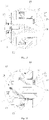
- the inner drum door 6 is hindered from being closed through the door closing hindering device 55, and the inner drum door 6 is opened by a certain angle A. So when a detected terminal 38 on the inner drum door 6 is not located in a sensing area 54 of the position sensor 33, the position detection device can more accurately judge whether the inner drum door 6 is locked.
- the problems in the prior art are solved, such as when the inner drum door 6 is not locked, the inner drum door 6 is still closed on the inner drum opening or the opening angle is very small, the position detection device misjudges that the inner drum door 6 is locked. After the washing machine is started, damage or accidents caused by a high rotation speed of the inner drum 17 .
- the door closing hindering device 55 can be arranged on the inner drum door 6 or on the inner drum 17. Or, the door closing hindering device is arranged between the inner drum door 6 and the inner drum 17.
- the door closing hindering device 55 is an elastic piece arranged on the inner drum door 6, on the inner drum 17 or between the inner drum 17 and the inner drum door 6.
- the elastic piece has certain elasticity. The two elastic ends of the elastic piece abut against the inner wall of the inner drum and the inner wall of the inner drum door. One end of the elastic piece is connected to the inner drum 17 or the inner drum door 6, and the other end of the elastic piece is connected with the inner drum 17 and the inner drum door 6 in an abutting mode.
- the two ends of the elastic piece are connected with the inner drum 17 and the inner drum door 6 in an abutting mode.
- the elastic piece generates certain resistance when closing the inner drum door 6., And if the inner drum door 6 is not locked, the inner drum door 6 can be bounced open by a certain angle.
- the inner drum door 6 is connected to the inner drum opening through an inner drum door shaft 56 in an opened/closed mode.
- the elastic piece is a torsional spring arranged on the inner drum door shaft 56 in a sleeving mode.
- the torsion spring includes a torsion spring body with spiral shape, and the torsion spring body is arranged on the inner drum door shaft 56 in a sleeving mode. Two end parts of the torsion spring body extend outwards in a straight line mode to form a front straight line section and a rear straight line section which are arranged in an included angle mode. The front straight line section and the rear straight line section abut against the inner wall of the inner drum 17 and the inner side wall of the inner drum door 6 respectively.
- the torsion spring When the inner drum door 6 is closed, the torsion spring generates force for pulling the two sections back to the original positions to prevent the inner drum door 6 from being closed. If the inner drum door 6 is not locked, the torsion spring releases compressed and stored angular energy, and the front straight line section and the rear straight line section act on the inner drum 17 and the inner drum door 6 respectively to generate rotating force to open the inner drum door 6 by a certain angle.
- the detected terminal 38 on the inner drum door 6 is located outside the sensing area 54 of the position sensor 33, the position detection device can more accurately judge whether the inner drum door is locked, and the possibility of misjudgment is reduced.
- the extension end of the front straight line section of the torsion spring is bent to form a first connecting part used for being connected with the inner drum door 6, and the extension end of the rear straight line section of the torsion spring is bent to form a second connecting part used for being connected with the inner drum 17.
- the first connecting part and the second connecting part are of hook structures and are hooked to the inner drum door 6 and the inner drum 17.
- the first connecting part and the second connecting part are of spiral structures and are connected to connecting structures correspondingly arranged on the inner drum door 6 and the inner drum 17 in a sleeving mode.
- the front straight line section and a rear straight line section which are formed by extending two end parts of the torsion spring are connected to the inner drum door 6 and the inner drum 17 in a hooking or sleeving mode respectively.
- the two end parts of the torsion spring can be stably connected with the inner drum door 6 and the inner drum 17 so that the end parts of the torsion spring are not disengaged from the inner drum door 6 and the inner drum 17.
- the door closing hindering device 55 is a hydraulic telescopic rod, pneumatic telescopic rod or compression spring, of which one end is connected with the inner wall of the inner drum 17 and the other end is abutted against the inner wall of the inner drum door 6.
- the door closing hindering device 55 is a hydraulic telescopic rod, pneumatic telescopic rod or compression spring, of which one end is connected with the inner wall of the inner drum door 6 and the other end is abutted against the inner wall of the inner drum 17.
- the door closing hindering device 55 is a hydraulic telescopic rod, pneumatic telescopic rod or compression spring which is connected between the inner drum door 6 and the inner drum 17.
- the door closing hindering device 55 can also be other telescopic and foldable mechanisms capable of generating certain resistance to closing of the inner drum door 6.
- the position detection device in the embodiment includes a detected terminal 38 arranged on the inner drum door 6, and a position sensor 33 arranged corresponding to the detected terminal 38 and provided with a sensing area 54 capable of sensing the detected terminal 38.
- the drum washing machine further includes an outer drum 18 which is arranged outside the inner drum 17 in a sleeving mode and is coaxial with the inner drum 17.
- the position sensor 33 is arranged on the outer drum 18 and corresponds to the position of the detected terminal 38.
- the drum washing machine further includes a shell 19 arranged outside the inner drum 17, and the position sensor 33 is arranged on the shell 19 and corresponds to the position of the detected terminal 38.
- the inner drum door 6 is locked on the inner drum 17 through a locking mechanism.
- the locking mechanism includes a locking piece 52 arranged on the inner drum door 6 and a locking groove 53 formed in the inner drum corresponding to the locking piece 52.
- the detected terminal 38 is arranged on the locking piece 52.
- the locking piece 52 is a lock tongue arranged on the inner drum door 6, and the locking groove 53 is a lock hole formed in the inner drum openin of the inner drum 17.
- the position detection device is an electromagnetic type sensor, the position sensor 33 is an electromagnetic sensor, and the detected terminal 38 is a permanent magnet rotor.
- the position detection device is a photoelectric type position sensor, the position sensor 33 is a photoelectric sensor, and the detected terminal 38 is a shading plate.
- the position detection device is a differential voltage type sensor, the position sensor 33 is a differential voltage sensor, and the detected terminal 38 is an armature.
- the position detection device is an eddy current type sensor, the position sensor 33 is an eddy current sensor, and the detected terminal 38 is a metal plate.
- the position detection device is Hall type sensor, the position sensor 33 is a Hall sensor, and the detected terminal 38 is a permanent magnet.
- the position detection device is a reed switch type sensor
- the position sensor 33 is a reed switch sensor
- the detected terminal 38 is a permanent magnet.
- the detected terminal 38 is arranged at the position, close to the locking piece 52, of the inner drum door 6, and the position sensor 33 is arranged at the position, close to a drum opening of the inner drum 17, of the inner wall of the outer drum 18.
- the technical problem solved by the embodiment is the same as that solved by the Embodiment IX, and the technical solution is further optimized on the basis of the solution of the Embodiment IX, and the specific solution is as follows.
- the drum washing machine provided by the embodiment of the invention includes an inner drum 17 with an inner drum opening; an inner drum door 6 mounted at the inner drum opening in an opened/closed manner; a position detection device, used for detecting whether the inner drum door 6 is successfully locked; and a magnetic element, used for attracting/repelling the inner drum door 6 and applying force for hindering closing of the inner drum door 6.
- the non-contact magnetic element is used for hindering closing of the inner drum door.
- the friction loss between the non-contact magnetic element and the inner drum door and the friction loss between the non-contact magnetic element and the inner drum are reduced, the damage rate is low, the structure is simple, sensitivity is higher, and controllability is high.
- the magnetic element in the embodiment can be independently arranged and can also be arranged on the washing machine together with the door closing hindering device in the Embodiment IX, so that the double insurance effect is achieved, the probability of misjudgment of the position detection device is further reduced. If one of the door closing hindering device and the magnetic element is only arranged and is broken, the effect of preventing the door body from being closed cannot be achieved. The above accident is prevented by arrangement of magnetic element together with the door closing hindering device.
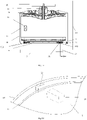
- the magnetic element includes a first magnetic element 61 arranged on the inner wall of the inner drum door 6 and a second magnetic element 62 arranged at the drum opening of the inner drum 17 corresponding to the first magnetic element 61.
- the first magnetic element 61 and the second magnetic element 62 repel with each other.
- force for hindering closing of the inner drum door 6 is generated.
- the repelling force generated by the first magnetic element 61 and the second magnetic element 62 enables the inner drum door 6 to be opened at a certain angle.
- the inner drum door 6 and the inner drum 17 are provided with installation positions used for installing the first magnetic element 61 and the second magnetic element 62. Fixing can be achieved in a clamping or bonding mode, the structure is simple, and installation is convenient.
- the washing machine further includes a shell 19 arranged outside the inner drum 17.
- the magnetic element includes a first magnetic element 61 arranged on the outer wall of the inner drum door 6 and a second magnetic element 62 arranged on the inner wall of the shell 19 corresponding to the first magnetic element 61.
- the first magnetic element 61 and the second magnetic element 62 attract each other.
- the second magnetic element 62 arranged on the shell 19 generates magnetic attraction force to the first magnetic element 61 located on the inner drum door 6 so as to attract the inner drum door 6 and hinder closing of the inner drum door 6. If the inner drum door 6 is not locked, the generated attraction force enables the inner drum door 6 to be opened by a certain angle.
- a machine door 5 is arranged at the position, corresponding to the inner drum door 6, of the shell 19.
- the machine door 5 is connected to the shell 19 through a machine door shaft 57.
- the magnetic element includes the first magnetic element 61 arranged on the outer wall of the inner drum door 6 and the second magnetic element 62 arranged on the inner wall of the machine door 5 and corresponding to the first magnetic element 61.
- the first magnetic element 61 and the second magnetic element 62 attract with each other.
- the second magnetic element 62 arranged on the machine door 5 generates magnetic attraction force to the first magnetic element 61 located on the inner drum door 6, then the inner drum door 6 is attracted, and closing of the inner drum door 6 is hindered. If the inner drum door 6 is not locked, the generated attractive force enables the inner drum door 6 to be opened at a certain angle.
- the first magnetic element 61 is a magnetic induction piece or a permanent magnet arranged on the inner drum door 6.
- the magnetic induction piece can be made of iron, nickel, cobalt and other metal magnetic materials.
- the second magnetic element 62 is an electromagnetic module arranged on the shell 19 or the machine door 5 corresponding to the first magnetic element 61.
- the electromagnetic module is an electrified coil or an electromagnet.
- the magnetism of the adopted electromagnetic module can be controlled through on-off of current, the intensity of the magnetism can be controlled through the magnitude of the current or the number of turns of a coil, and it is easy to be controlled.
- the intensity of the magnetism attracting the inner drum door can also be regulated and controlled by controlling the magnitude of the current.
- the phenomenon is avoided that the inner drum door cannot be attracted due to too weak magnetism, or that the inner drum door is damaged to a certain extent or is difficult to close due to too strong magnetism,.
- the control unit of the washing machine controls the electromagnetic module to be powered off, resources are saved. The situation that the magnetic element always generates force for hindering closing of the door body after the inner drum door is locked is avoided, and the sealing effect of the inner drum door is affected.
- the opposite magnetic poles of the first magnetic element 61 and the second magnetic element 62 face with each other.
- the first magnetic element 61 and the second magnetic element 62 are both permanent magnets.
- the first magnetic element 61 is a magnetic induction piece such as iron, nickel, cobalt and other metal magnetic materials
- the second magnetic element 62 is a permanent magnet.
- the first magnetic element 61 is a permanent magnet.
- the second magnetic element 62 is a magnetic induction piece.
- the combination of the permanent magnet and the magnetic induction piece or the combination of the permanent magnet and the permanent magnet is adopted to generate resistance for preventing the inner drum door 6 from being closed.
- the inner drum door 6 is opened by a certain angle, and the washing machine is simple in structure, low in cost and strong in applicability.
- the position detection device in the embodiment includes a detected terminal 38 arranged on an inner drum door 6; and a position sensor 33 arranged corresponding to the detected terminal 38 and provided with a sensing area 54 capable of sensing the detected terminal.
- the position sensor 33 is a reed switch type sensor.
- the specific structure, the arrangement position and the arrangement mode of the position sensor in the embodiment are the same as those in the Embodiments VII-IX, and are not repeated here.
Landscapes
- Engineering & Computer Science (AREA)
- Textile Engineering (AREA)
- Main Body Construction Of Washing Machines And Laundry Dryers (AREA)
- Control Of Washing Machine And Dryer (AREA)
Abstract
Description
- The invention belongs to the technical field of washing machine, and particularly relates to a drum washing machine.
- As a most widely used household appliance in daily life of people, the washing machine helps people get rid of the trouble of washing laundry and brings great convenience to people. However, the washing machine has certain defects such as taking long time and using large water. Along with social development, the water resource is becoming more and more important as an important natural resource, and the water saving awareness of people is improved. In order to improve the water saving function of the washing machine, an inner drum structure without holes is adopted. However, the biggest problem of the inner drum structure without holes is in a problem to close in seal an inner drum door. Due to negligence of a user, the inner drum door is not locked in place, but a position detection device does not detect the above situation to cause water leakage under the conditions of washing or rinsing and dewatering, and a door body is not locked in place and rotation at a high speed to cause damage and the like occur.
- According to an inner drum washing machine without holes in the prior arts, the situation that an inner drum door is unlocked but still closed on an inner drum opening or the opening angle is very small easily occurs, so that the inner drum door is actually unlocked. Whereas the position detection device for detecting whether the inner drum door is locked or not misjudges that the inner drum door is locked. After the washing machine is started, the inner drum rotates at a high speed, and safety accidents are likely to happen. Therefore, those skilled in the field urgently need to develop a washing machine which can more accurately judge whether the inner drum door is locked or not.
- In view of this, the invention is proposed.
- The technical problem to be solved by the invention is to overcome the defects in the prior art, and the invention provides a drum washing machine capable of accurately judging whether the inner drum door is locked or not.
- In order to achieve the objective, the following technical solution is adopted.
- A drum washing machine includes: an inner drum with an inner drum opening; an inner drum door, mounted at the inner drum opening in an opened and closed manner; a position detection device, configured to detect whether the inner drum door is locked or not; and a door closing hindering device, configured to apply force on the inner drum door for hindering being closed.
- In one embodiment, the door closing hindering device is arranged on the inner drum; or the door closing hindering device is arranged on the inner drum door; or, the door closing hindering device is arranged between the inner drum and the inner drum door.
- In one embodiment, the door closing hindering device is an elastic piece arranged between the inner drum and the inner drum door, and two elastic ends of the elastic piece abut against the inner drum and the inner drum door.
- In one embodiment, the inner drum door is connected to the inner drum opening through an inner drum door shaft. The elastic piece is a torsional spring arranged on the inner drum door shaft in a sleeving mode. The torsional spring includes a torsional spring body in a spiral shape, the torsional spring body is arranged on the inner drum door shaft in a sleeving mode, and two end parts of the torsion spring body extend outwards and respectively abut against the inner drum and the inner drum door.
- In one embodiment, the door closing hindering device is a hydraulic telescopic rod, an gas pressure telescopic rod or a compression spring.
- In one embodiment, the position detection device includes: a detected terminal arranged on the inner drum door; and a position sensor arranged correspondingly to the detected terminal and provided with a sensing area capable of sensing the detected terminal.
- In one embodiment, the drum washing machine further includes an outer drum which is arranged outside the inner drum in a sleeving mode and is coaxial with the inner drum, and the position sensor is arranged on the outer drum and corresponds to the position of the detected terminal.
- In one embodiment, the drum washing machine further includes a shell arranged outside the inner drum, and the position sensor is arranged on the shell and corresponds to the position of the detected terminal.
- In one embodiment, the inner drum door is locked on the inner drum through a locking mechanism. The locking mechanism includes a locking piece arranged on the inner drum door and a locking groove arranged in the inner drum corresponding to the locking piece. The detected terminal is arranged on the locking piece.
- In one embodiment, the position detection device is an electromagnetic type sensor, the position sensor is an electromagnetic sensor, and the detected terminal is a permanent magnet rotor;
- or the position detection device is a photoelectric type position sensor, the position sensor is a photoelectric sensor, and the detected terminal is a shading plate;
- or the position detection device is a differential voltage type sensor, the position sensor is a differential voltage sensor, and the detected terminal is an armature;
- or the position detection device is an eddy current type sensor, the position sensor is an eddy current sensor, and the detected terminal is a metal plate;
- or the position detection device is a Hall type sensor, the position sensor is a Hall sensor, and the detected terminal is a permanent magnet;
- or the position detection device is a reed switch type sensor, the position sensor is a reed switch sensor, and the detected terminal is a permanent magnet.
- In one embodiment, the door closing hindering device includes a magnetic element which is able to attract and repel the inner drum door, and applies force on the inner drum door for hindering being closed.
- In one embodiment, the magnetic element includes a first magnetic element arranged on the inner drum door and a second magnetic element correspondingly arranged at the inner drum opening, and the first magnetic element and the second magnetic element repel each other.
- In other embodiment, same magnetic poles of the first magnetic element and the second magnetic element face with each other.
- In other embodiment, both the first magnetic element and the second magnetic element are permanent magnets.
- In one embodiment, the drum washing machine further includes a shell arranged outside the inner drum. The magnetic element includes a first magnetic element arranged on the inner drum door and a second magnetic element correspondingly arranged on the shell, and the first magnetic element and the second magnetic element attract each other.
- In one embodiment, the drum washing machine further includes a shell arranged outside the inner drum, a machine door is arranged at the position, corresponding to the inner drum door, of the shell, and the magnetic element includes a first magnetic element arranged on the inner drum door and a second magnetic element correspondingly arranged on the machine door, and the first magnetic element and the second magnetic element attract each other.
- In one embodiment, the first magnetic element is a magnetic induction piece or a permanent magnet arranged on the inner drum door, and the second magnetic element is an electromagnetic module arranged correspondingly.
- In one embodiment, anisotropic magnetic poles of the first magnetic element and the second magnetic element face with each other.
- In other embodiment, both the first magnetic element and the second magnetic element are permanent magnets.
- In one embodiment, the first magnetic element is a magnetic induction piece, and the second magnetic element is a permanent magnet. Alternatively the first magnetic element is a permanent magnet, and the second magnetic element is a magnetic induction piece.
- In one embodiment, the position detection device includes: a detected terminal arranged on the inner drum door; and a position sensor arranged correspondingly to the detected terminal and provided with a sensing area capable of sensing the detected terminal.
- In one embodiment, the position sensor is a reed switch sensor.
- In one embodiment, the drum washing machine further includes an outer drum which is arranged outside the inner drum in a sleeving mode and coaxial with the inner drum, and the position sensor is correspondingly arranged on the outer drum and corresponds to the position of the detected terminal.
- Alternatively, the drum washing machine further includes a shell arranged outside the inner drum, and the position sensor is correspondingly arranged on the shell and corresponds to the position of the detected terminal.
- In one embodiment, the inner drum door is locked on the inner drum through a locking mechanism. The locking mechanism includes a locking piece arranged on the inner drum door and a locking groove arranged in the inner drum corresponding to the locking piece, and the detected terminal is arranged on the locking piece.
- After the above technical solution is adopted, compared with the prior art, the invention has the following beneficial effects.
- According to the drum washing machine provided by the invention, through the arrangement of the door closing hindering device, when the inner drum door is closed, the force on the inner drum door for hindering being closed is generated. If the inner drum door is not locked, the inner drum door is opened by a certain angle, so that the detected terminal on the inner drum door is not in the sensing range of the position sensor, and the probability of misjudgment of the position detection device is reduced. The problems in the prior art is avoided, such as the inner drum door is unlocked, but the inner drum door is still closed at the inner drum opening or the opening angle is very small, so that the position detection device misjudges that the inner drum door is locked, thereby after the washing machine is started, the inner drum rotates at a high speed to cause safety accidents.
- The specific implementation modes of the invention are further described in detail in combination with attached drawings.
-
-
Fig. 1 shows a principle schematic diagram of the drum washing machine in Embodiment I of the invention; -
Fig. 2 shows a principle schematic diagram of the drum washing machine in Embodiment II of the invention (a first implementation mode); -
Fig. 3 shows a principle schematic diagram of the drum washing machine in the Embodiment II of the invention (a second implementation mode); -
Fig. 4 shows a principle schematic diagram of the drum washing machine in the Embodiment II of the invention (a third implementation mode); -
Fig. 5 shows a principle schematic diagram of the drum washing machine in Embodiment III of the invention; -
Fig. 6 shows a local magnification diagram inFig. 5 of the drum washing machine in the Embodiment III of the invention (in a depressurization state); -
Fig. 7 shows a local magnification diagram inFig. 5 of the drum washing machine in the Embodiment III of the invention (in a pressurization state); -
Fig. 8 shows a principle schematic diagram of the drum washing machine in Embodiment IV of the invention; -
Fig. 9 shows a local magnification diagram inFig. 8 of the drum washing machine in the Embodiment IV of the invention (in a depressurization state of the first implementation mode); -
Fig. 10 shows a local magnification diagram inFig. 8 of the drum washing machine in the Embodiment IV of the invention (in a pressurization state of the first implementation mode); -
Fig. 11 shows a local magnification diagram inFig. 8 of the drum washing machine in the Embodiment IV of the invention (in a depressurization state of the second implementation mode); -
Fig. 12 shows a local magnification diagram inFig. 8 of the drum washing machine in the Embodiment IV of the invention (in a pressurization state of the second implementation mode); -
Fig. 13 shows a principle schematic diagram of the drum washing machine in Embodiment V of the invention; -
Fig. 14 shows a bottom view of the drum washing machine in the Embodiment V of the invention; -
Fig. 15 shows a three-dimensional structure diagram of the drum washing machine in the Embodiment V of the invention; -
Fig. 16 shows a local magnification diagram inFig. 15 of the drum washing machine in the Embodiment V of the invention; -
Fig. 17 shows a principle schematic diagram of the drum washing machine in Embodiment VI of the invention (the first implementation mode); -
Fig. 18 shows a principle schematic diagram of the drum washing machine in the Embodiment VI of the invention (the second implementation mode); -
Fig. 19 is a structural diagram of the drum washing machine in Embodiment VII of the invention; -
Fig. 20 shows a local magnification diagram inFig. 19 in the Embodiment VII of the invention; -
Fig. 21 shows a principle schematic diagram of the drum washing machine in Embodiment VIII of the invention; -
Fig. 22 shows a principle schematic diagram of the drum washing machine in Embodiment IX of the invention; -
Fig. 23 shows another principle schematic diagram of the drum washing machine in the Embodiment IX of the invention; -
Fig. 24 shows a principle schematic diagram of the drum washing machine in Embodiment X of the invention (the first implementation mode); -
Fig. 25 shows a principle schematic diagram of the drum washing machine in the Embodiment X of the invention (the second implementation mode); and -
Fig. 26 shows a principle schematic diagram of the drum washing machine in the Embodiment X of the invention (the third implementation mode). - In the drawings, 1. flow sensor; 2. upper deck plate; 3. detergent box; 4. master controller; 5. machine door; 6. inner drum door; 611. rotating part; 612. pushing part; 7. water outlet; 8. drainage pipeline; 9. bottom foot; 10. pushing rod mechanism; 11. one-way valve plug; 12. bearing; 13. shaft; 14. hollow channel; 15. first dynamic sealing structure; 16. driving motor; 17. inner drum; 18. outer drum; 19. shell; 20. water inlet valve; 21. water measuring tank; 22. water level detection device; 23. water tank draining pump; 24. overflow hole; 25. water tank drain valve; 26. heating device; 27. pressure equalizing hole channel; 28. pressurization hole channel; 29. negative pressure safety valve; 30. depressurization hole channel; 31. positive pressure safety valve; 32. mounting bracket; 33. position sensor; 34. fixing knot; 35. locking mechanism; 38. detected terminal; 39. locking groove; 40. locking rod; 41. locking motor; 42. outer drum rear wall; 43. lifting rib; 46. inner drum door pushing and closing device; 52. locking piece; 53. locking groove; 54. sensing area; 55. door closing hindering device; 56. inner drum door shaft; 57. machine door shaft; 61. first magnetic element; 62. second magnetic element.
- To make the objectives, technical solutions, and advantages of embodiments of the present invention clearer, the technical solutions will be clearly and completely described below with reference to the accompanying drawings in the embodiments of the present invention. The following embodiments are used to describe the present invention but not to limit the scope of the present invention.
- As shown in
Fig. 1-Fig. 26 , a drum washing machine which is provided with an inner drum without holes and is of a front-open structure is provided by the embodiment. The drum washing machine is simple in structure, and washing/rinsing water does not need to be between the inner drum and the outer drum, so that the washing water used in the washing machine is greatly reduced. The possibility of dirt adhesion between the inner drum and the outer drum is avoided. The user health and the user experience are greatly improved, and water resources are greatly saved. - The drum washing machine of the embodiment is provided with a
shell 19. Theshell 19 includes anupper deck plate 2, a front plate, a rear back plate and a bottom plate.Bottom feet 9 are fixedly installed on the bottom plate and used for supporting the whole washing machine. Anouter drum 18 is arranged in theshell 19, and aninner drum 17 is coaxially arranged in theouter drum 18. Theouter drum 18 is mainly used for collecting water drained out of theinner drum 17 and water drained out of theinner drum 17 in high-speed centrifugal dewatering process. The inner drum rotates, and preferably, liftingribs 43 are arranged, so that the laundry are continuously lifted, dropped and beaten cleaned. Theinner drum 17 is of a structure without holes. Theouter drum 18 is provided with a central mounting hole for mounting and fixing abearing 12. Aninner drum shaft 13 fixedly connected with theinner drum 17 penetrates through thebearing 12 and is connected with a drivingmotor 16. Aninner drum door 6 capable of being opened/closed is installed on a drum opening in the front portion of theinner drum 17, and therefore theinner drum 17 is of a sealed cabin structure. - A
machine door 5 capable of being opened/closed is installed on theshell 19. - The embodiment of the invention mainly solves the problem of how to accurately determine the water inflow of the drum washing machine with aN inner drum without holes, and the specific solution is as follows.
- The drum washing machine includes an
inner drum 17 and a water inlet pipeline communicating with theinner drum 17. Theinner drum 17 is a drum without holes and contains washing water when laundry are washed. Aflow sensor 1 used for detecting water inflow is arranged on the water inlet pipeline. - According to the embodiment, the
flow sensor 1 is arranged on the water inlet pipeline to monitor the water inflow. When the set water inlet amount is reached, awater inlet valve 20 is closed, and water feeding is completed. According to the embodiment, the flow sensor is adopted to solve the water feeding problem of the drum washing machine having the inner drum without holes according to the set water level, the washing effect is ensured, the structure is simple, and control is convenient. - Further, the drum washing machine of the embodiment includes a
water inlet valve 20 and adetergent box 3. The water inlet pipeline includes a first water inlet pipe and a second water inlet pipe, the outlet end of thewater inlet valve 20 is communicated with thedetergent box 3 through the first water inlet pipe, and the outlet end of thedetergent box 3 is communicated with theinner drum 17 through the second water inlet pipe. Theflow sensor 1 is arranged on the first water inlet pipe or the second water inlet pipe. - Preferably, the
flow sensor 1 is arranged on the first water inlet pipe, so that the detergent in the detergent box can be prevented from entering theflow sensor 1. - The drum washing machine of the embodiment includes a
master controller 4, and theflow sensor 1 is electrically connected with themaster controller 4 through a circuit. Themaster controller 4 can collect the water inflow of theinner drum 17 in real time, and thewater inlet valve 20 is closed when the set water inflow is reached. - As an implementation mode of the embodiment, the
flow sensor 1 is a rotor flow sensor, or a turbine flow sensor, or an ultrasonic flow sensor, or an electromagnetic flow sensor, or a pore plate flow sensor. - According to the embodiment, the
flow sensor 1 can be arranged at any position of the water inlet pipeline. Preferably, theflow sensor 1 is arranged behind thewater inlet valve 20 to accurately meter the flow of water entering the sealedinner drum 17. Theflow sensor 1 is connected with themaster controller 4 through a circuit, and themaster controller 4 can collect the water inflow of theinner drum 17 in real time, so that thewater inlet valve 20 is closed when the set water inflow is reached. - In order to feed water into the inner drum without holes, the drum washing machine of the embodiment includes a driving
motor 16 and aninner drum shaft 13, and the drivingmotor 16 is in transmission connection with theinner drum 17 through theinner drum shaft 13 to drive theinner drum 17 to rotate. Ahollow channel 14 communicating with the interior of theinner drum 17 is formed in theinner drum shaft 13, and the water inlet pipeline is communicated with the hollow channel of theinner drum shaft 13. - Specifically, the
inner drum shaft 13 is connected with the drivingmotor 16. The drivingmotor 16 includes a stator and a rotor, and the rotor is fixedly connected with theinner drum shaft 13. A through hole is formed in the center of the rotor, and the water inlet pipeline penetrates through the through hole of the rotor to be communicated with thehollow channel 14 of theinner drum shaft 13. - Further, a first
dynamic sealing structure 15 is arranged between the water inlet pipeline and the through hole of the rotor, and a second sealing structure is arranged between the through hole of the rotor and thehollow channel 14 of theinner drum shaft 13. - In order to achieve drainage of the inner drum without holes, the drum washing machine of the embodiment includes an
outer drum 18. An inner drum drainage hole is formed in the side wall of theinner drum 17, a one-way valve plug 11 which is normally closed is installed in the inner drum drainage hole, and a pushingrod mechanism 10 used for ejecting the one-way valve plug 11 open for drainage is installed on theouter drum 18. - Preferably, the
outer drum 18 is further provided with a locking mechanism used for stopping rotation of the inner drum 17.After the locking mechanism locks the inner drum, the pushingrod mechanism 10 ejects the one-way valve plug 11 open for drainage. - In order to achieve dewatering of the inner drum without holes, a plurality of dewatering holes are formed in the side wall of the
inner drum 17, and centrifugal valves are installed on the dewatering holes. The centrifugal valves are opened under the action of dewatering centrifugal force to conduct dewatering and drainage. - The embodiment of the invention also provides a control method of the drum washing machine. The washing machine executes a washing/rinsing program. In the water feeding process, the flow sensor detects the water inflow value in real time, the washing machine calculates the water inflow according to the water inflow value and the water feeding time, and water feeding is stopped when the water inflow reaches the set water inflow of the washing machine.
- The drum washing machine is provided with a plurality of water inflow values which can be selected by a user, and water is fed into the washing machine according to the water inflow value selected by the user.
- The drum washing machine has a laundry weighing function, and water can be fed after determining the water inflow value according to the weight of laundry.
- As shown in
Fig. 2-Fig. 4 , the drum washing machine includes aninner drum 17 and a water inlet pipeline. The inner drum is an inner drum without holes and contains washing water when laundry are washed. The drum washing machine further includes a water measuring device used for measuring the water inflow, the water inlet pipeline is communicated with the water measuring device, and the water measuring device is communicated with the inner drum. - Through the arrangement of the water measuring device of the drum washing machine of the embodiment, water enters the water measuring device for quantitative measurement before entering the
inner drum 1. The water measuring frequency of the water measuring device is determined according to the set water level, and therefore the problem that water enters the drum washing machine having the inner drum without holes according to the set water level is solved, the washing effect is good, the structure is simple, and it is convenient to be controlled. - Further, the water measuring device includes a
water measuring tank 21, and thewater measuring tank 21 is provided with a water inlet and a water outlet. The water inlet is communicated with a water inlet pipeline, and the water outlet is communicated with theinner drum 17. The water outlet is provided with a water outlet control device which is used for controlling the water outlet to be opened when the water amount in thewater measuring tank 21 reaches a set value. - As an implementation mode of the embodiment, as shown in
Fig. 2 , thewater measuring tank 21 is arranged at the bottom of theinner drum 17. The water measuring device includes a waterlevel detection device 22 used for detecting the water level in thewater measuring tank 21. The water outlet control device is a watertank drainage pump 23. When it is detected by the waterlevel detection device 22 that the water level in thewater measuring tank 21 reaches a set value, the watertank drainage pump 23 is started to pump water in thewater measuring tank 21 into theinner drum 17. - As an implementation mode of the embodiment, as shown in
Fig. 3 , thewater measuring tank 21 is arranged above theinner drum 17. The water measuring device includes a waterlevel detection device 22 used for detecting the water level in the water measuring water tank. The water outlet control device is a watertank drain valve 25. The watertank drain valve 25 is opened to drain water in thewater measuring tank 21 into the inner drum when it is detected by the waterlevel detection device 22 that the water level in thewater measuring tank 21 reaches a set value. - The water
level detection device 22 of the embodiment is a liquid level sensor. The liquid level sensor includes an gas chamber and a sensor unit, and the gas chamber is communicated with the water measuring tank. Or, the waterlevel detection device 22 includes a plurality of water level detection probes which are arranged in the water measuring tank in the depth direction of the water measuring tank. - As one implementation mode of the embodiment, the
water measuring tank 21 is arranged above theinner drum 17. The water outlet is formed in the bottom wall of thewater measuring tank 21. The water outlet control device is a water tank one-way valve for keeping the water outlet normally closed. When the water amount in the water measuring tank reaches a certain value, the water tank one-way valve is opened under the water pressure gravity. After water in thewater measuring tank 21 is discharged into theinner drum 17, the water tank one-way valve resets to keep the water outlet closed. - An
overflow hole 24 is formed in thewater measuring tank 21 of the embodiment, and theoverflow hole 24 is connected with an overflow pipeline used for guiding out water overflowing out of the water measuring tank. - Preferably, the drum washing machine includes a
drainage pipeline 8, and the overflow pipeline is communicated with thedrainage pipeline 8. - As an implementation mode of the embodiment, as shown in
Fig. 4 , the water measuring device includes aheating device 26 arranged in thewater measuring tank 21 and a water temperature detection device for detecting the water temperature in the water measuring tank. - The embodiment of the invention also provides a control method of the drum washing machine. The drum washing machine controls the washing water to enter the water measuring tank in executing a washing program or a rinsing program. When the water amount in the water measuring tank reaches a set value, the water feeding is stopped, the water in the water measuring tank is completely discharged into the inner drum. Then the drum washing machine is restarted to feed water into the water measuring tank, and the above process is circulated until the water level in the inner drum reaches a set value, and water feeding is ended.
- Further, the drum washing machine controls the washing water to enter the water measuring tank. When the water amount in the water measuring tank reaches a set value, water feeding is stopped, the heating device is controlled to operate to heat the washing water. When it is detected by the water temperature detection device that the water temperature in the water measuring tank reaches the set value, the water in the water measuring tank is completely discharged into the inner drum.
- The embodiment of the invention mainly solves how to ensure unbalanced gas pressure of a sealed cabin of a drum washing machine having an inner drum without holes. Specifically, the washing water in the sealed cabin is backflowed to a pipe network due to the fact that water of an electromagnetic valve is suddenly cut off, particularly water of a tap water pipe network is cut off, and negative pressure is formed; or water is difficult to enter into the inner drum due to gas existing inside.
- As shown in
Fig. 5-Fig. 7 , the drum washing machine of the embodiment includes aninner drum 17 which is without holes and used for containing washing water when laundry are washed. The drum washing machine further includes a gas pressure balance mechanism used for communicating theinner drum 17 with the external environment to balance the gas pressure in the inner drum. - When feeding water, gas in the sealed cabin of the inner drum is pressed and can overflow through the balance mechanism, and gas pressure balance is kept.
- When feeding water is suddenly cut off, external atmosphere can quickly enter the sealed cabin of the inner drum and destroy suck-back, and gas pressure balance is kept. Therefore washing water is prevented from being sucked into a tap water pipe network.
- Under other conditions, for example, during dewatering, the gas pressure balance mechanism can also keep the gas pressure balance of the inner drum.
- As an implementation mode of the embodiment, the gas pressure balance mechanism includes a pressure equalizing
hole channel 27 arranged on theinner drum 17. One end, communicating with the interior of theinner drum 17, of the pressure equalizinghole channel 27 is arranged at the position, close to a rotating center shaft, of theinner drum 17 and is higher than the highest water level position in theinner drum 17. - The drum washing machine of the embodiment includes a driving
motor 16 and aninner drum shaft 13, and the drivingmotor 16 is in transmission connection with theinner drum 17 through theinner drum shaft 13 to drive theinner drum 17 to rotate. The pressure equalizinghole channel 27 is formed in theinner drum shaft 13 to communicating the interior of theinner drum 17 with the external environment, and the highest water level in theinner drum 17 is lower than theinner drum shaft 13. Therefore, water in the inner drum can be prevented from flowing out of the pressure equalizing hole channel. - The drum washing machine of the embodiment includes an
outer drum 18, in which theinner drum 17 is arranged. Water discharged from theinner drum 17 is discharged through theouter drum 18. Aninner drum door 6 for closing the inner drum is installed on a drum opening of theinner drum 17. A drum opening of theouter drum 18 is open. One end of the pressure equalizinghole channel 27 is communicated with the interior of theinner drum 17, and the other end of the pressure equalizinghole channel 27 is arranged in theouter drum 18 and communicated with theouter drum 18. In this way, extreme conditions are prevented, and water discharged from the pressure equalizing hole channel can be collected in theouter drum 18. - Further, an inner drum drainage hole is formed in the side wall of the
inner drum 17, an one-way valve plug 11 being normally closed is installed on the inner drum drainage hole, and a pushingrod mechanism 10 used for ejecting the one-way valve plug 11 open for drainage is installed on theouter drum 18. - Preferably, the
outer drum 18 is further provided with a locking mechanism used for locking rotation of the inner drum. After the locking mechanism locks the inner drum, the pushing rod mechanism ejects the one-way valve plug open for drainage. - Further, the drum washing machine of the embodiment includes a water inlet pipeline, a
hollow channel 14 communicating with the interior of theinner drum 17 is arranged in theinner drum shaft 13, and the water inlet pipeline is communicated with thehollow channel 14 of theinner drum shaft 13. The pressure equalizinghole channel 27 and thehollow channel 14 are respectively communicated with the interior of theinner drum 17 and are arranged in interval. Therefore, gas in the sealed cabin of the inner drum can be smoothly discharged to keep gas pressure balance in the inner drum, and water leakage caused by the fact that inflow water is directly discharged from the pressure equalizinghole channel 27 is prevented. - Specifically, the
hollow channel 14 extends from one end to the other end in the central axis direction of the inner drum shaft. The pressure equalizing hole channel includes a first hole channel section and a second hole channel section. The first hole channel section is parallel to the hollow channel, and one end of the first hole channel section is communicated with the interior of the inner drum. One end of the second hole channel section is communicated with the first hole channel section, and the other end passes through the outer peripheral wall of the inner drum shaft and is communicated with the interior of the outer drum. - Preferably, the second hole channel section is perpendicular to the first hole channel section to form an pressure equalizing hole channel with L-shape.
- Further, the
inner drum shaft 13 is connected with a drivingmotor 16. The drivingmotor 16 includes a stator and a rotor, and the rotor is fixedly connected with the inner drum shaft. A through hole is formed in the center of the rotor, and the water inlet pipeline penetrates through the through hole of the rotor to be communicated with the hollow channel of the inner drum shaft. - Preferably, a first dynamic sealing structure is arranged between the water inlet pipeline and the through hole of the rotor, and a second sealing structure is arranged between the through hole of the rotor and the hollow channel of the inner drum shaft.
- According to the drum washing machine in the embodiment, the multiple dewatering holes are formed in the side wall of the
inner drum 17, and the centrifugal valves are installed on the dewatering holes. The centrifugal valves are opened under the action of the centrifugal force to conduct dewatering and drainage. - The embodiment mainly solves how to keep unbalanced gas pressure of a sealed cabin of a drum washing machine having an inner drum without holes. Specifically, the washing water in the sealed cabin is backflowed to a pipe network due to the fact that feeding water is suddenly cut off by an electromagnetic valve, particularly feeding water is cut off by a tap water pipe network, and negative pressure is formed; or water is difficult to enter into the inner drum due to gas existing inside.
- As shown in
Fig. 8-Fig. 12 , the drum washing machine of the embodiment includes aninner drum 17 which is without holes and is used for containing washing water when laundry are washed. The drum washing machine includes a pressurization mechanism and/or a depressurization mechanism which are/is used for connecting the inner drum with the external environment so as to balance gas pressure in theinner drum 17. - The pressurization mechanism of the embodiment includes a
pressurization hole channel 28 and a negativepressure safety valve 29, and the negativepressure safety valve 29 is arranged in thepressurization hole channel 28 and used for opening thepressurization hole channel 28 unidirectionally when the internal pressure of theinner drum 17 is smaller than the atmospheric pressure of the external environment, and external environment gas enters theinner drum 17 through thepressurization hole channel 28 to increase the pressure. The negativepressure safety valve 29 is not closed until the internal gas pressure of theinner drum 17 is balanced with the gas pressure of the external environment. - The depressurization mechanism of the embodiment includes a
depressurization hole channel 30 and a positivepressure safety valve 31. Thedepressurization hole channel 30 is formed in the position, close to the rotating center shaft, of theinner drum 17 and is higher than the highest water level position in theinner drum 17. The positivepressure safety valve 31 is arranged in thedepressurization hole channel 30, and used to open unidirectionally thedepressurization hole channel 30 for depressurization when the internal pressure of theinner drum 17 is larger than the gas pressure of the external environment. The positivepressure safety valve 31 is not closed until the internal gas pressure of theinner drum 17 is balanced with the gas pressure of the external environment. - As shown in
Fig. 9 , when feeding water, gas in a sealed cabin of theinner drum 17 is pressed. Once the gas pressure is larger than a set value of the positive pressure safety valve, the positive pressure safety valve is opened and gas can overflow through the depressurization hole channel, so that the gas pressure balance is ensured. - As shown in
Fig. 10 , when feeding water is suddenly cut off, gas in a sealed cabin of theinner drum 17 is pressed. Once the gas pressure is smaller than a set value of the positive pressure safety valve, external atmosphere can quickly enter the sealed cabin and destroy suck-back, gas pressure balance is kept, and washing water is prevented from being sucked into a tap water pipe network. - In the other conditions, for example, during dewatering, the gas pressure balance mechanism can also keep the gas pressure balance of the inner drum.
- The drum washing machine of the embodiment includes a driving
motor 16 and aninner drum shaft 13, and the drivingmotor 16 is in transmission connection with theinner drum 17 through theinner drum shaft 13 to drive theinner drum 17 to rotate. Thepressurization hole channel 28 and/or thedepressurization hole channel 30 are/is formed in theinner drum shaft 13 and connects the interior of theinner drum 17 with the external environment, and the highest water level in theinner drum 17 is lower than theinner drum shaft 13. - The drum washing machine of the embodiment includes an
outer drum 18, and theinner drum 17 is arranged in theouter drum 18. Water discharged from theinner drum 17 is discharged through theouter drum 18. Aninner drum door 6 for closing the inner drum is installed at a drum opening of theinner drum 17. A drum opening of theouter drum 18 is open. One end of thepressurization hole channel 28 or thedepressurization hole channel 30 is communicated with the interior of theinner drum 17, and the other end is arranged in theouter drum 18 and communicated with theouter drum 18. - The drum washing machine of the embodiment includes a water inlet pipeline. A
hollow channel 14 communicating with the interior of theinner drum 17 is formed in theinner drum shaft 13, and the water inlet pipeline is communicated with thehollow channel 14 of theinner drum shaft 13. Thedepressurization hole channel 30 and thehollow channel 14 are respectively communicated with the interior of theinner drum 17 and are arranged in interval. - As shown in
Fig. 9 and Fig. 10 , thehollow channel 14 extends from one end to the other end along the central axis direction of theinner drum shaft 13. Thedepressurization hole channel 30 includes a first hole channel section and a second hole channel section. The first hole channel section is parallel to the hollow channel, one end of the first hole channel section is communicated with the interior of the inner drum. one end of the second hole channel section is communicated with the first hole channel section, and the other end passes through the outer peripheral wall of the inner drum shaft and is communicated with the interior of the outer drum.
preferably, the second hole channel section is perpendicular to the first hole channel section to form an depressurization hole channel with L-shape. - The drum washing machine of the embodiment includes a water inlet pipeline. A
hollow channel 14 communicating with the interior of theinner drum 17 is formed in theinner drum shaft 13, and the water inlet pipeline is communicated with thehollow channel 14 of theinner drum shaft 13; and thepressurization hole channel 28 is communicated with thehollow channel 14. - Further, the
hollow channel 14 extends from one end to the other end in the direction of the central axis of theinner drum shaft 13. One end of thepressurization hole channel 28 is communicated with thehollow channel 14, and the other end of thepressurization hole channel 28 passes through the peripheral wall of theinner drum shaft 13 to be communicated with the interior of theouter drum 18. - Preferably, the
pressurization hole channel 28 and thehollow channel 14 are perpendicular to each other. - The inner drum shaft of the embodiment is connected with a driving motor. The driving motor includes a stator and a rotor, and the rotor is fixedly connected with the inner drum shaft. A through hole is formed in the center of the rotor, and the water inlet pipeline penetrates through the through hole of the rotor to be communicated with the hollow channel of the inner drum shaft.
- Preferably, a first dynamic sealing structure is arranged between the water inlet pipeline and the through hole of the rotor, and a second sealing structure is arranged between the through hole of the rotor and the hollow channel of the inner drum shaft.
- As shown in
Fig. 11 and Fig. 12 , apressurization hole channel 28 and adepressurization hole channel 30 are both arranged on theinner drum shaft 13. Openings communicating with the atmosphere are both formed in the inner side of theouter drum 18; and Openings communicating the sealed cabin of theinner drum 17 are both arranged on the inner side of thehollow channel 14 of theinner drum shaft 13. - Preferably, the
pressurization hole channel 28 and thedepressurization hole channel 30 are both arranged on theinner drum shaft 13. Openings communicating with the atmosphere are both arranged on the inner side of theouter drum 18; and openings communicating the sealed cabin of theinner drum 17 are both arranged on the inner side of the sealed cabin. - As shown in
Figs 13-16 , the drum washing machine of the embodiment includes aninner drum 17 which is without holes and is used for containing washing water when laundry are washed. The drum washing machine further includes a position detection device used for detecting the position of the inner drum. - The drum washing machine of the embodiment includes a driving
motor 16 and aninner drum shaft 13. The drivingmotor 16 includes a stator and a rotor, and the rotor is fixedly connected with theinner drum shaft 13 to drive aninner drum 17 to rotate. The position detection device includes aposition sensor 33 and a detectedterminal 38, the detectedterminal 38 is arranged on the rotor, and theposition sensor 33 is fixed at a position corresponding to the detectedterminal 38. - The drum washing machine of the embodiment includes an
outer drum 18. Theposition sensor 33 is arranged on the side, close to the drivingmotor 16, of theouter drum 18, and theposition sensor 33 and the detectedterminal 38 are correspondingly arranged in interval. - As an implementation mode of the embodiment, the position sensor is an electromagnetic position sensor, a photoelectric position sensor, a differential voltage type sensor, an eddy current type sensor, a capacitance type sensor, a reed switch type sensor, or a Hall type sensor.
- The drum washing machine of the embodiment includes a
locking mechanism 35 used for locking rotation of the inner drum. The position detection device is used for detecting whether theinner drum 17 is locked in appropriate place after thelocking mechanism 35 locks theinner drum 17, and/or when the position detection device detects that theinner drum 17 rotates to a set position, thelocking mechanism 35 locks theinner drum 17. - Further, the
locking mechanism 35 is installed on the side wall, close to the drivingmotor 16, of theouter drum 18. Thelocking mechanism 35 includes a lockingrod 40 moving in a telescopic mode and a lockingmotor 41 driving the lockingrod 40 to move in a telescopic mode. A rotor of the drivingmotor 16 is provided with a lockinggroove 39 corresponding to the lockingrod 40 and matched with the lockingrod 40. When the lockingrod 40 is driven by the lockingmotor 41 to stretch out and be inserted into the lockinggroove 39, theinner drum 17 is locked. - According to the drum washing machine of the embodiment, an inner drum drainage hole is formed in the side wall of an
inner drum 17, a one-way valve plug 11 which is normally closed is installed on the inner drum drainage hole, and a pushingrod mechanism 10 used for ejecting the one-way valve plug open for drainage is installed on the outer drum. After thelocking mechanism 35 locks theinner drum 17, the pushingrod mechanism 10 ejects the one-way valve plug 11 open for drainage. - Further, the pushing rod mechanism is installed on the outer drum. The pushing rod mechanism includes a pushing rod moving telescopically and a motor driving the pushing rod to move telescopically. The pushing rod penetrates through the drum wall of the outer drum and is inserted into the drainage hole of the inner drum to eject the one-way valve plug open for drainage.
- The drum washing machine of the embodiment includes a main controller. The position detection sensor, the locking motor and the pushing rod motor for driving the pushing rod are all electrically connected with the main controller.
- According to the drum washing machine of the embodiment, a plurality of dewatering holes are formed in the side wall of the inner drum, and the centrifugal valves are installed on the dewatering holes. The centrifugal valves are opened under the effect of dewatering centrifugal force to conduct dewatering and drainage.
- The washing machine of the embodiment is provided with a
position sensor 33 which is arranged on theouter drum 18 or the drivingmotor 16. And particularly theposition sensor 33 is arranged on the rear portion of theouter drum 18 and a rotor framework for rotation of the drivingmotor 16. - The
position sensor 33 detects the position of the detectedterminal 38 on the rotating rotor framework, converts the position into a signal and feeds the signal back to themain controller 4 of the washing machine through acircuit 43. - The position of the detected
terminal 38 on the rotor framework corresponds to the position of the rotating inner drum. - The washing machine of the embodiment is provided with a mounting
bracket 32. A fixingknot 34 is fixed on the rear the outer drum. A locking motor, a locking rod and a position sensor are mounted on the mountingbracket 32. The rotor framework of the driving motor is provided with the locking groove and the detectedterminal 38. - As shown in
Fig. 17-18 , the drum washing machine of the embodiment includes aninner drum 17 and anouter drum 18. Theinner drum 17 is without holes and contains washing water when laundry are washed. Theouter drum 18 is coaxially arranged outside theinner drum 17 and used for collecting water discharged from theinner drum 17 and discharging the water through a drainage pipeline. The drum washing machine further includes a position detection device which is arranged on theouter drum 18 and used for detecting the position of the inner drum. - Further, the position detection device includes a
position sensor 33 and a detectedterminal 38. The detectedterminal 38 is arranged on theinner drum 17, and theposition sensor 33 is arranged on the inner wall of theouter drum 18 and corresponds to the detectedterminal 38 on theinner drum 17. - Preferably, the detected
terminal 38 is arranged on the side wall of theinner drum 17, and theposition sensor 33 is arranged on the inner side wall of theouter drum 18. The circumference of theinner drum 17 where the detectedterminal 38 is arranged and the circumference of theouter drum 18 where theposition sensor 33 is arranged are concentrically arranged. - Preferably, the
position sensor 33 is arranged on the inner side wall of the upper portion of theouter drum 18. - Preferably, the position sensor is an electromagnetic position sensor, a photoelectric position sensor, a differential voltage type sensor, an eddy current type sensor, a capacitance type sensor, a reed switch type sensor, or a Hall type sensor.
- The drum washing machine of the embodiment includes a
locking mechanism 35 used for locking the inner drum for not rotating. The position detection device is used for detecting whether theinner drum 17 is locked in appropriate place after thelocking mechanism 35 locks theinner drum 17, and/or when the position detection device detects that theinner drum 17 rotates to a set position, thelocking mechanism 35 locks the inner drum. - Further, the
locking mechanism 35 is installed on theouter drum 18. Thelocking mechanism 35 includes a lockingrod 40 moving telescopically and a lockingmotor 41 for driving the lockingrod 40 to move telescopically. A lockinggroove 39 matched with the lockingrod 40 is formed on theinner drum 17 corresponding to the lockingrod 40. When the lockingrod 40 is driven by the lockingmotor 41 to stretch out and be inserted into the lockinggroove 39, theinner drum 17 is locked. - As shown in
Fig. 8 , as one implementation mode of the embodiment, a liftingrib 43 is mounted at the lockinggroove 39, so that the lockinggroove 39 is hidden. Further, or the detectedterminal 38 is installed in the liftingrib 43. - As one implementation mode of the embodiment, an inner drum drainage hole is formed in the side wall of the
inner drum 17, and a one-way valve plug 11 which is normally closed is installed on the inner drum drainage hole. A pushingrod mechanism 10 used for ejecting the one-way valve plug 11 open for drainage is installed on theouter drum 18. After thelocking mechanism 35 locks theinner drum 17, the pushingrod mechanism 10 ejects the one-way valve plug 11 open for drainage. - Further, the pushing
rod mechanism 10 is installed on theouter drum 18. The pushingrod mechanism 10 includes a pushing rod moving telescopically and a motor driving the pushing rod to move telescopically. The pushing rod penetrates through the drum wall of the outer drum to be inserted into the drainage hole of the inner drum to eject the one-way valve plug open for drainage. - The drum washing machine of the embodiment includes a main controller 4.,The position detection sensor, the locking motor and the motor for driving the pushing rod are all electrically connected with the main controller.
- According to the drum washing machine of the embodiment, a plurality of dewatering holes are formed in the side wall of the inner drum, and the centrifugal valves are installed on the dewatering holes. The centrifugal valves are opened under the effect of dewatering centrifugal force to conduct dewatering and drainage.
- As shown in
Fig. 19 and Fig. 20 , the washing machine in the embodiment includes aninner drum 17 and aninner drum door 6, theinner drum 17 is provided with an inner drum opening, and theinner drum door 6 is installed on the inner drum opening of the inner drum in an opened/closed manner. The washing machine further includes a position detection device used for detecting whether the body of the inner drum door is successfully closed, the situation that the body of the inner drum door is unlocked and water leakage is caused under the washing or rinsing and dewatering situation is avoided. Or the problem is solved, such as the body of the inner drum door is not successfully locked and damage is caused under rotation at a high speed due to negligence of a user. - The position detection device includes a
position sensor 33 and a detectedterminal 38. The detectedterminal 38 is arranged on theinner drum door 6, and theposition sensor 33 is arranged at the position corresponding to the detectedterminal 38. Theposition sensor 33 is fixed, and the detected terminal 38 moves along with theinner drum door 6 in the opening/closing process of theinner drum door 6. The position between the detected terminal 38 an theposition sensor 33 changes along with rotation of theinner drum door 6, a generated signal value changes, and the washing machine judges whether theinner drum door 6 is successfully closed according to the received signal value. - The
inner drum door 6 is provided with a locking structure used for being buckled with theinner drum 17, and the detectedterminal 38 is arranged on the locking structure. - The washing machine further includes an
outer drum 18 which is arranged outside theinner drum 17 in a sleeving mode and is coaxial with theinner drum 17, and theposition sensor 33 is arranged on theouter drum 18 and corresponds to the position of the detectedterminal 38. Preferably, theposition sensor 33 is arranged on the outer wall of theouter drum 18 and corresponds to the position of the detectedterminal 38. Theposition sensor 33 is fixed, the detected terminal 38 moves along with theinner drum door 6 in the opening/closing process of theinner drum door 6. The position between detected terminal 38 an theposition sensor 33 changes along with rotation of theinner drum door 6, and a generated signal value changes. The drum washing machine judges whether theinner drum door 6 is successfully closed according to the received signal value. - The washing machine further includes a
shell 19, theinner drum 17 is arranged in theshell 19, and theposition sensor 33 is arranged on theshell 19 and corresponds to the position of the detected terminal. - The position detection device is an electromagnetic position sensor and includes a permanent magnet rotor and an electromagnetic sensor. The permanent magnet rotor is the detected
terminal 38, and the electromagnetic sensor is theposition sensor 33. Alternatively the position detection device is a photoelectric position sensor which includes a shading plate and a photoelectric sensor. The shading plate is the detectedterminal 38, and the photoelectric sensor is theposition sensor 33. Alternatively the position detection device is a differential voltage type sensor which includes an armature and a differential voltage sensor. The armature is the detectedterminal 38, and the differential voltage sensor is theposition sensor 33. Alternatively the position detection device is an eddy current type sensor which includes a metal plate and an eddy current sensor. The metal plate is the detectedterminal 38, and the eddy current sensor is theposition sensor 33. Alternatively the position detection device is a capacitive sensor which includes a moving electrode, a fixed electrode and a capacitive sensor. The moving electrode is the detectedterminal 38, and the fixed electrode and the capacitive sensor are theposition sensor 33. Alternatively the position detection device is a reed switch type sensor which includes a magnet and a reed switch sensor. The magnet is the detectedterminal 38, and the reed switch sensor is theposition sensor 33. Alternatively the position detection device is a Hall type sensor which includes a permanent magnet and a Hall sensor. The permanent magnet is the detectedterminal 38, and the Hall sensor is theposition sensor 33. - The washing machine further includes a
main controller 4, and themain controller 4 is electrically connected with the position sensor. - The embodiment further includes a control method of the washing machine, comprising the
main controller 4 of the washing machine judging whether theinner drum door 6 is successfully closed according to a signal detected by the position detection device. The situation that the inner drum door is unlocked and water leakage is caused under the washing or rinsing and dewatering situation is avoided. Or the problem is solved, such as the door body is not successfully locked and damage is caused under rotation at a high speed due to negligence of a user. - The signal value responding to a position between the detected
terminal 38 and theposition sensor 33 when theinner drum door 6 is successfully closed is input into themain controller 4 of the drum washing machine, and as a reference signal value to judge whether the body of the inner drum door is successfully closed. - When a signal value responding to a position between the detected
terminal 38 and theposition sensor 33 and received by themain controller 4 of the washing machine is equal to the reference signal value, themain controller 4 of the washing machine judges that theinner drum door 6 is successfully closed. When a signal value which is received by themain controller 4 of the washing machine and responding to a position between the detectedterminal 38 and theposition sensor 33 is different from the reference signal value, themain controller 4 of the washing machine judges that theinner drum door 6 is not successfully closed, and a user is reminded to close theinner drum door 6. The situation that the inner drum door is unlocked and water leakage is caused under the washing or rinsing and dewatering situation is avoided. Or the problem is avoided, such as the door body is not successfully locked and damage is caused under rotation at a high speed due to negligence of a user. - The position detection device in the embodiment can be used as an auxiliary device to assist the
main controller 4 in judging the rotating state of theinner drum 17 and locking the motor. - The embodiment of the invention mainly solves the problem of how to automatically and successfully close an inner drum door arranged at a drum opening of an inner drum, and the specific solution is as follows.
- In combination with
Fig. 19 andFig. 21 , the washing machine provided by the embodiment includes: ashell 19, aninner drum 17 arranged inside theshell 19 and containing washing water when washing laundry, and aninner drum door 6, installed on a drum opening of theinner drum 17 in an opened/closed manner. The washing machine further includes an inner drum door pushing and closingdevice 46 which is arranged on theshell 19 and is used for pushing theinner drum door 6 to be closed. - According to the embodiment, the inner drum door pushing and closing
device 46 is arranged on theshell 19, so that theinner drum door 6 can be automatically pushed and closed without manual closing, the automation degree is higher. The problem that theinner drum door 6 is not closed due to negligence of a user can be effectively prevented, and the risk that theinner drum door 6 falls off due to high-speed rotation is avoided. - Further, the inner drum door pushing and closing
device 46 includes a power component and a linkage component which is connected with the power output end of the power component. The power component drives the linkage component to move and act on theinner drum door 6, and theinner drum door 6 is pushed to be closed. - Further, an opening is formed in the position, corresponding to a drum opening of the
inner drum 17, of theshell 19, amachine door 5 capable of being opened and closed is installed on the opening, and the inner drum door pushing and closingdevice 46 is arranged on themachine door 5 or the side, close to theinner drum door 6, of theshell 19. - According to one solution, the power component is the
machine door 5. The linkage component is a mechanical linkage mechanism connected to themachine door 5. When a user closes themachine door 5, acting force is applied to themachine door 5, and then themachine door 5 drives the mechanical linkage mechanism to act on theinner drum door 6, theinner drum door 6 is closed. Time and labor are saved since themachine door 5 and theinner drum door 6 are closed at the same time. The mechanical linkage mechanism can be a connecting rod mechanism or a linkage folding mechanism. - Preferably, the inner drum door pushing and closing
device 46 is an electric pushing and closing mechanism. Specifically, the power component is a motor arranged in the shell, and the linkage component is a cam mechanism or a cam connecting rod mechanism connected with the power output end of the motor. - As an alternative solution of the above solution, the power component is an oil pump arranged on the
shell 19, and the linkage component is an oil cylinder connected with the power output end of the oil pump. Or, the power component is a gas pump arranged on the shell, and the linkage component is an air cylinder connected with the power output end of the gas pump. - In the embodiment, the
inner drum door 6 includes arotating part 611 rotationally connected with theinner drum 17 through a hinge and a pushing and closingpart 612 arranged on a side opposite to therotating part 611. The inner drum door pushing and closingdevice 46 is arranged on themachine door 5 or theshell 19, corresponding to the pushing and closingpart 612. According to the lever principle, the inner drum door pushing and closingdevice 46 is arranged on the other side away from therotating part 611, it is more labor-saving and easier to close theinner drum door 6. - In the embodiment, the inner drum door pushing and closing
device 46 is an electric pushing and closing mechanism, so that automatic pushing and closing can be achieved. The controller is electrically connected with the motor or the oil pump or the gas pump through a circuit, it can be achieved that the inner drum door pushing and closingdevice 46 is electrically controlled, and automation and intelligence are better achieved. - The washing machine further includes an
outer drum 18 located in theshell 19, theinner drum 17 is rotatably arranged in theouter drum 18, and a position detection device is arranged in theouter drum 18 and used for detecting whether theinner drum door 6 is successfully closed. The position detection device includes a detectedterminal 38 and aposition sensor 33. Preferably, theposition sensor 33 is a reed switch type sensor, a Hall sensor, a photoelectric sensor, a differential voltage type sensor, an eddy current type sensor, or a capacitance type sensor. When the washing machine is detected that amachine door 5 is closed and locked, the position detection device detects whether theinner drum door 6 of the washing machine is closed. If yes, a control system of the washing machine controls the inner drum door pushing and closingdevice 46 to be kept in a closed state; and if not, the inner drum door pushing and closingdevice 46 is controlled to be started, and theinner drum door 6 is pushed to be closed. - The embodiment mainly solves the problem that a position detection device misjudges that an inner drum door is successfully locked due to the fact that the inner drum door is still closed at an inner drum opening or the opening angle of the inner drum door is very small when the inner drum door of the inner drum without holes of washing machine is actually unlocked, and the specific solution is as follows.
- As shown in
Fig. 22 andFig. 23 , the drum washing machine provided by the embodiment includes aninner drum 17 with an inner drum opening. Aninner drum door 6 is installed at the inner drum opening in an opened/closed mode. Theinner drum door 6 can be connected to the inner drum opening through a connecting piece or buckled to the inner drum opening. Theinner drum door 6 needs to be locked through a locking mechanism before the washing machine is started so that accidents caused by high-speed rotation of theinner drum 17 can be prevented. A position detection device, used for detecting whether theinner drum door 6 is successfully locked so as to avoid the situation that a user neglects that theinner drum door 6 is not locked or makes a mistake subjective judgment. The drum washing machine comprises a doorclosing hindering device 55, used for applying force for hindering closing of theinner drum door 6. When theinner drum door 6 is not locked, theinner drum door 6 is hindered from being closed through the doorclosing hindering device 55, and theinner drum door 6 is opened by a certain angle A. So when a detectedterminal 38 on theinner drum door 6 is not located in asensing area 54 of theposition sensor 33, the position detection device can more accurately judge whether theinner drum door 6 is locked. The problems in the prior art are solved, such as when theinner drum door 6 is not locked, theinner drum door 6 is still closed on the inner drum opening or the opening angle is very small, the position detection device misjudges that theinner drum door 6 is locked. After the washing machine is started, damage or accidents caused by a high rotation speed of theinner drum 17 . - In the embodiment, the door
closing hindering device 55 can be arranged on theinner drum door 6 or on theinner drum 17. Or, the door closing hindering device is arranged between theinner drum door 6 and theinner drum 17. In the embodiment, the doorclosing hindering device 55 is an elastic piece arranged on theinner drum door 6, on theinner drum 17 or between theinner drum 17 and theinner drum door 6. The elastic piece has certain elasticity. The two elastic ends of the elastic piece abut against the inner wall of the inner drum and the inner wall of the inner drum door. One end of the elastic piece is connected to theinner drum 17 or theinner drum door 6, and the other end of the elastic piece is connected with theinner drum 17 and theinner drum door 6 in an abutting mode. Or the two ends of the elastic piece are connected with theinner drum 17 and theinner drum door 6 in an abutting mode. The elastic piece generates certain resistance when closing the inner drum door 6., And if theinner drum door 6 is not locked, theinner drum door 6 can be bounced open by a certain angle. - Preferably, the
inner drum door 6 is connected to the inner drum opening through an innerdrum door shaft 56 in an opened/closed mode. The elastic piece is a torsional spring arranged on the innerdrum door shaft 56 in a sleeving mode. The torsion spring includes a torsion spring body with spiral shape, and the torsion spring body is arranged on the innerdrum door shaft 56 in a sleeving mode. Two end parts of the torsion spring body extend outwards in a straight line mode to form a front straight line section and a rear straight line section which are arranged in an included angle mode. The front straight line section and the rear straight line section abut against the inner wall of theinner drum 17 and the inner side wall of theinner drum door 6 respectively. When theinner drum door 6 is closed, the torsion spring generates force for pulling the two sections back to the original positions to prevent theinner drum door 6 from being closed. If theinner drum door 6 is not locked, the torsion spring releases compressed and stored angular energy, and the front straight line section and the rear straight line section act on theinner drum 17 and theinner drum door 6 respectively to generate rotating force to open theinner drum door 6 by a certain angle. When the detectedterminal 38 on theinner drum door 6 is located outside thesensing area 54 of theposition sensor 33, the position detection device can more accurately judge whether the inner drum door is locked, and the possibility of misjudgment is reduced. - More preferably, the extension end of the front straight line section of the torsion spring is bent to form a first connecting part used for being connected with the
inner drum door 6, and the extension end of the rear straight line section of the torsion spring is bent to form a second connecting part used for being connected with theinner drum 17. The first connecting part and the second connecting part are of hook structures and are hooked to theinner drum door 6 and theinner drum 17. Or the first connecting part and the second connecting part are of spiral structures and are connected to connecting structures correspondingly arranged on theinner drum door 6 and theinner drum 17 in a sleeving mode. The front straight line section and a rear straight line section which are formed by extending two end parts of the torsion spring are connected to theinner drum door 6 and theinner drum 17 in a hooking or sleeving mode respectively. The two end parts of the torsion spring can be stably connected with theinner drum door 6 and theinner drum 17 so that the end parts of the torsion spring are not disengaged from theinner drum door 6 and theinner drum 17. - In the embodiment, the door
closing hindering device 55 is a hydraulic telescopic rod, pneumatic telescopic rod or compression spring, of which one end is connected with the inner wall of theinner drum 17 and the other end is abutted against the inner wall of theinner drum door 6. Alternatively the doorclosing hindering device 55 is a hydraulic telescopic rod, pneumatic telescopic rod or compression spring, of which one end is connected with the inner wall of theinner drum door 6 and the other end is abutted against the inner wall of theinner drum 17. Alternatively the doorclosing hindering device 55 is a hydraulic telescopic rod, pneumatic telescopic rod or compression spring which is connected between theinner drum door 6 and theinner drum 17. The doorclosing hindering device 55 can also be other telescopic and foldable mechanisms capable of generating certain resistance to closing of theinner drum door 6. - The position detection device in the embodiment includes a detected terminal 38 arranged on the
inner drum door 6, and aposition sensor 33 arranged corresponding to the detectedterminal 38 and provided with asensing area 54 capable of sensing the detectedterminal 38. The drum washing machine further includes anouter drum 18 which is arranged outside theinner drum 17 in a sleeving mode and is coaxial with theinner drum 17. Theposition sensor 33 is arranged on theouter drum 18 and corresponds to the position of the detectedterminal 38. Or the drum washing machine further includes ashell 19 arranged outside theinner drum 17, and theposition sensor 33 is arranged on theshell 19 and corresponds to the position of the detectedterminal 38. - According to the embodiment, the
inner drum door 6 is locked on theinner drum 17 through a locking mechanism. The locking mechanism includes alocking piece 52 arranged on theinner drum door 6 and a lockinggroove 53 formed in the inner drum corresponding to thelocking piece 52. The detectedterminal 38 is arranged on thelocking piece 52. Preferably, the lockingpiece 52 is a lock tongue arranged on theinner drum door 6, and the lockinggroove 53 is a lock hole formed in the inner drum openin of theinner drum 17. - In the embodiment, the position detection device is an electromagnetic type sensor, the
position sensor 33 is an electromagnetic sensor, and the detectedterminal 38 is a permanent magnet rotor. Or the position detection device is a photoelectric type position sensor, theposition sensor 33 is a photoelectric sensor, and the detectedterminal 38 is a shading plate. Or the position detection device is a differential voltage type sensor, theposition sensor 33 is a differential voltage sensor, and the detectedterminal 38 is an armature. Or the position detection device is an eddy current type sensor, theposition sensor 33 is an eddy current sensor, and the detectedterminal 38 is a metal plate. Or the position detection device is Hall type sensor, theposition sensor 33 is a Hall sensor, and the detectedterminal 38 is a permanent magnet. - Preferably, the position detection device is a reed switch type sensor, the
position sensor 33 is a reed switch sensor, and the detectedterminal 38 is a permanent magnet. The detectedterminal 38 is arranged at the position, close to thelocking piece 52, of theinner drum door 6, and theposition sensor 33 is arranged at the position, close to a drum opening of theinner drum 17, of the inner wall of theouter drum 18. - When a lock tongue on the
inner drum door 6 is locked in a lock groove of the inner drum, theinner drum door 6 is locked, then the torsional spring cannot open theinner drum door 6 by a certain angle, so that a permanent magnet located on theinner drum door 6 is located in thesensing area 54 of the reed switch sensor, the reed switch sensor forms a circuit, and a control unit of the washing machine judges that theinner drum door 6 is locked. When the lock tongue is not locked in the lock groove, theinner drum door 6 is unlocked, the force generated by the torsion spring forcibly opens theinner drum door 6 at an included angle A shown in theFig. 23 , so that the permanent magnet is located outside thesensing area 54 of the reed switch sensor, the reed switch sensor is in an broken circuit at the moment, the control unit of the washing machine judges that the inner drum door is unlocked, and then an alarm is given. A user is reminded to lock the inner drum door. - The technical problem solved by the embodiment is the same as that solved by the Embodiment IX, and the technical solution is further optimized on the basis of the solution of the Embodiment IX, and the specific solution is as follows.
- As shown in
Figs 24-26 , the drum washing machine provided by the embodiment of the invention includes aninner drum 17 with an inner drum opening; aninner drum door 6 mounted at the inner drum opening in an opened/closed manner; a position detection device, used for detecting whether theinner drum door 6 is successfully locked; and a magnetic element, used for attracting/repelling theinner drum door 6 and applying force for hindering closing of theinner drum door 6. According to the embodiment, the non-contact magnetic element is used for hindering closing of the inner drum door. Compared with the door closing hindering device in the Embodiment IX, the friction loss between the non-contact magnetic element and the inner drum door and the friction loss between the non-contact magnetic element and the inner drum are reduced, the damage rate is low, the structure is simple, sensitivity is higher, and controllability is high. - The magnetic element in the embodiment can be independently arranged and can also be arranged on the washing machine together with the door closing hindering device in the Embodiment IX, so that the double insurance effect is achieved, the probability of misjudgment of the position detection device is further reduced. If one of the door closing hindering device and the magnetic element is only arranged and is broken, the effect of preventing the door body from being closed cannot be achieved. The above accident is prevented by arrangement of magnetic element together with the door closing hindering device.
- In one embodiment, as shown in
Fig. 24 , the magnetic element includes a firstmagnetic element 61 arranged on the inner wall of theinner drum door 6 and a secondmagnetic element 62 arranged at the drum opening of theinner drum 17 corresponding to the firstmagnetic element 61. The firstmagnetic element 61 and the secondmagnetic element 62 repel with each other. When theinner drum door 6 is closed, force for hindering closing of theinner drum door 6 is generated. If theinner drum door 6 is not locked, the repelling force generated by the firstmagnetic element 61 and the secondmagnetic element 62 enables theinner drum door 6 to be opened at a certain angle. - The same magnetic poles of the first
magnetic element 61 and the secondmagnetic element 62 face with each other. More preferably, the firstmagnetic element 61 and the secondmagnetic element 62 are two permanent magnets, and the magnetism of the permanent magnets cannot be weakened or disappear, so that the trouble caused by frequent magnetizing is avoided. Theinner drum door 6 and theinner drum 17 are provided with installation positions used for installing the firstmagnetic element 61 and the secondmagnetic element 62. Fixing can be achieved in a clamping or bonding mode, the structure is simple, and installation is convenient. - In another implementation mode, the washing machine further includes a
shell 19 arranged outside theinner drum 17. The magnetic element includes a firstmagnetic element 61 arranged on the outer wall of theinner drum door 6 and a secondmagnetic element 62 arranged on the inner wall of theshell 19 corresponding to the firstmagnetic element 61. The firstmagnetic element 61 and the secondmagnetic element 62 attract each other. When theinner drum door 6 is closed, the secondmagnetic element 62 arranged on theshell 19 generates magnetic attraction force to the firstmagnetic element 61 located on theinner drum door 6 so as to attract theinner drum door 6 and hinder closing of theinner drum door 6. If theinner drum door 6 is not locked, the generated attraction force enables theinner drum door 6 to be opened by a certain angle. - Alternatively, a
machine door 5 is arranged at the position, corresponding to theinner drum door 6, of theshell 19. Themachine door 5 is connected to theshell 19 through amachine door shaft 57. The magnetic element includes the firstmagnetic element 61 arranged on the outer wall of theinner drum door 6 and the secondmagnetic element 62 arranged on the inner wall of themachine door 5 and corresponding to the firstmagnetic element 61. The firstmagnetic element 61 and the secondmagnetic element 62 attract with each other. When theinner drum door 6 is closed, the secondmagnetic element 62 arranged on themachine door 5 generates magnetic attraction force to the firstmagnetic element 61 located on theinner drum door 6, then theinner drum door 6 is attracted, and closing of theinner drum door 6 is hindered. If theinner drum door 6 is not locked, the generated attractive force enables theinner drum door 6 to be opened at a certain angle. - In the above implementation mode, the following two specific solutions are provided.
- According to the first solution, as shown in the
Fig. 25 , the firstmagnetic element 61 is a magnetic induction piece or a permanent magnet arranged on theinner drum door 6. The magnetic induction piece can be made of iron, nickel, cobalt and other metal magnetic materials. The secondmagnetic element 62 is an electromagnetic module arranged on theshell 19 or themachine door 5 corresponding to the firstmagnetic element 61. The electromagnetic module is an electrified coil or an electromagnet. The magnetism of the adopted electromagnetic module can be controlled through on-off of current, the intensity of the magnetism can be controlled through the magnitude of the current or the number of turns of a coil, and it is easy to be controlled. The intensity of the magnetism attracting the inner drum door can also be regulated and controlled by controlling the magnitude of the current. The phenomenon is avoided that the inner drum door cannot be attracted due to too weak magnetism, or that the inner drum door is damaged to a certain extent or is difficult to close due to too strong magnetism,. After the position detection device detects that the inner drum door is successfully locked, the control unit of the washing machine controls the electromagnetic module to be powered off, resources are saved. The situation that the magnetic element always generates force for hindering closing of the door body after the inner drum door is locked is avoided, and the sealing effect of the inner drum door is affected. - According to the second solution, as shown in the
Fig. 26 , the opposite magnetic poles of the firstmagnetic element 61 and the secondmagnetic element 62 face with each other. Preferably, the firstmagnetic element 61 and the secondmagnetic element 62 are both permanent magnets. According to the alternative solution of the above solution, the firstmagnetic element 61 is a magnetic induction piece such as iron, nickel, cobalt and other metal magnetic materials, and the secondmagnetic element 62 is a permanent magnet. Or, the firstmagnetic element 61 is a permanent magnet. The secondmagnetic element 62 is a magnetic induction piece. The combination of the permanent magnet and the magnetic induction piece or the combination of the permanent magnet and the permanent magnet is adopted to generate resistance for preventing theinner drum door 6 from being closed. Theinner drum door 6 is opened by a certain angle, and the washing machine is simple in structure, low in cost and strong in applicability. - As shown in
Figs 24 to 26 , the position detection device in the embodiment includes a detected terminal 38 arranged on aninner drum door 6; and aposition sensor 33 arranged corresponding to the detectedterminal 38 and provided with asensing area 54 capable of sensing the detected terminal. Preferably, theposition sensor 33 is a reed switch type sensor. The specific structure, the arrangement position and the arrangement mode of the position sensor in the embodiment are the same as those in the Embodiments VII-IX, and are not repeated here. - The above is only the preferred embodiments of the invention, and does not limit the invention in any form, although the invention is disclosed by the preferred embodiments, the preferred embodiments are not used for limiting the invention, and any skilled person familiar with the invention can make some changes or modifications as equivalent embodiments by using the technical contents mentioned above without departing from the technical solution of the invention. However, any simple modifications, equivalent changes and modifications made to the above embodiments according to the technical essence of the invention without departing from the technical solution of the invention still belong to the scope of the solution of the invention.
Claims (20)
- A drum washing machine, comprising :an inner drum with an inner drum opening;an inner drum door, mounted at the inner drum opening in an opened and closed manner;a position detection device, configured to detect whether the inner drum door is locked; anda door closing hindering device, configured to apply force for hindering closing of the inner drum door.
- The drum washing machine according to claim 1, wherein the door closing hindering device is arranged on the inner drum or on the inner drum door; or
the door closing hindering device is arranged between the inner drum and the inner drum door. - The drum washing machine according to claim 1, wherein the door closing hindering device is an elastic piece arranged between the inner drum and the inner drum door, and two elastic ends of the elastic piece abut against the inner drum and the inner drum door.
- The drum washing machine according to claim 3, wherein the inner drum door is connected to the inner drum opening through an inner drum door shaft, the elastic piece is a torsional spring arranged on the inner drum door shaft in a sleeving mode, the torsional spring comprises a torsional spring body with spiral shape, the torsional spring body is arranged on the inner drum door shaft in a sleeving mode, and two end parts of the torsion spring body extend outwards and respectively abut against the inner drum and the inner drum door.
- The drum washing machine according to claim 1, wherein the door closing hindering device is a hydraulic telescopic rod, a gas pressure telescopic rod, or t a compression spring.
- The drum washing machine according to claim 1, wherein the position detection device comprises:a detected terminal, arranged on the inner drum door; anda position sensor, arranged corresponding to the detected terminal and provided with a sensing area capable of sensing the detected terminal.
- The drum washing machine according to claim 6, comprising, an outer drum which is arranged outside the inner drum in a sleeving mode and is coaxial with the inner drum, wherein the position sensor is arranged on the outer drum and corresponds to the position of the detected terminal.
- The drum washing machine according to claim 6, comprising a shell arranged outside the inner drum, wherein the position sensor is arranged on the shell and corresponds to the position of the detected terminal.
- The drum washing machine according to claim 6, wherein the inner drum door is locked on the inner drum through a locking mechanism, the locking mechanism comprises a locking piece arranged on the inner drum door and a locking groove arranged in the inner drum corresponding to the locking piece, and the detected terminal is arranged on the locking piece.
- The drum washing machine according to claim 6, wherein the position detection device is an electromagnetic type sensor, the position sensor is an electromagnetic sensor, and the detected terminal is a permanent magnet rotor;or the position detection device is a photoelectric type position sensor, the position sensor is a photoelectric sensor, and the detected terminal is a shading plate;or the position detection device is a differential voltage type sensor, the position sensor is a differential voltage sensor, and the detected terminal is an armature;or the position detection device is an eddy current type sensor, the position sensor is an eddy current sensor, and the detected terminal is a metal plate;or the position detection device is a Hall type sensor, the position sensor is a Hall sensor, and the detected terminal is a permanent magnet;or the position detection device is a reed switch type sensor, the position sensor is a reed switch sensor, and the detected terminal is a permanent magnet.
- The drum washing machine according to any one of claims 1-10, wherein the door closing hindering device comprises a magnetic element which attracts and repels the inner drum door, and applies force for hindering closing of the inner drum door.
- The drum washing machine according to claim 11, wherein the magnetic element comprises a first magnetic element arranged on the inner drum door and a second magnetic element correspondingly arranged on the inner drum opening, and the first magnetic element and the second magnetic element repel each other;preferably, same magnetic poles of the first magnetic element and the second magnetic element face with each other; andmore preferably, both the first magnetic element and the second magnetic element are permanent magnets.
- The drum washing machine according to claim 11, comprising a shell arranged outside the inner drum, wherein the magnetic element comprises a first magnetic element arranged on the inner drum door and a second magnetic element correspondingly arranged on the shell, and the first magnetic element and the second magnetic element attract each other.
- The drum washing machine according to claim 11, comprising a shell arranged outside the inner drum, wherein a machine door is arranged at the position, corresponding to the inner drum door, of the shell,
the magnetic element comprises a first magnetic element arranged on the inner drum door and a second magnetic element correspondingly arranged on the machine door, and the first magnetic element and the second magnetic element attract each other. - The drum washing machine according to claim 13 or 14, wherein the first magnetic element is a magnetic induction piece or a permanent magnet arranged on the inner drum door, and the second magnetic element is an electromagnetic module.
- The drum washing machine according to claim 13 or 14, wherein opposite magnetic poles of the first magnetic element and the second magnetic element face with each other; and
preferably, both the first magnetic element and the second magnetic element are permanent magnets. - The drum washing machine according to claim 13 or 14, wherein the first magnetic element is a magnetic induction piece, and the second magnetic element is a permanent magnet; or,
the first magnetic element is a permanent magnet, and the second magnetic element is a magnetic induction piece. - The drum washing machine according to claim 11, wherein the position detection device comprises:a detected terminal, arranged on the inner drum door; anda position sensor, arranged corresponding to the detected terminal and provided with a sensing area capable of sensing the detected terminal;preferably, the position sensor is a reed switch sensor.
- The drum washing machine according to claim 18, comprising an outer drum which is arranged outside the inner drum in a sleeving mode and coaxial with the inner drum, and the position sensor is arranged on the outer drum and corresponds to the position of the detected terminal;
or, the drum washing machine further comprises a shell arranged outside the inner drum, and the position sensor is arranged on the shell and corresponds to the position of the detected terminal. - The drum washing machine according to claim 18, wherein the inner drum door is locked on the inner drum through a locking mechanism, the locking mechanism comprises a locking piece arranged on the inner drum door and a locking groove arranged in the inner drum corresponding to the locking piece, and the detected terminal is arranged on the locking piece.
Applications Claiming Priority (3)
| Application Number | Priority Date | Filing Date | Title |
|---|---|---|---|
| CN201910552434.5A CN112127104A (en) | 2019-06-25 | 2019-06-25 | A drum washing machine |
| CN201910552596.9A CN112127105A (en) | 2019-06-25 | 2019-06-25 | Drum washing machine |
| PCT/CN2020/097065 WO2020259405A1 (en) | 2019-06-25 | 2020-06-19 | Front-loading washing machine |
Publications (2)
| Publication Number | Publication Date |
|---|---|
| EP3992346A1 true EP3992346A1 (en) | 2022-05-04 |
| EP3992346A4 EP3992346A4 (en) | 2022-08-17 |
Family
ID=74061203
Family Applications (1)
| Application Number | Title | Priority Date | Filing Date |
|---|---|---|---|
| EP20832111.7A Withdrawn EP3992346A4 (en) | 2019-06-25 | 2020-06-19 | FRONT LOADING WASHING MACHINE |
Country Status (2)
| Country | Link |
|---|---|
| EP (1) | EP3992346A4 (en) |
| WO (1) | WO2020259405A1 (en) |
Families Citing this family (1)
| Publication number | Priority date | Publication date | Assignee | Title |
|---|---|---|---|---|
| CN115839018B (en) * | 2021-09-18 | 2026-01-23 | 青岛胶州海尔洗涤电器有限公司 | Wall-mounted washing machine |
Family Cites Families (13)
| Publication number | Priority date | Publication date | Assignee | Title |
|---|---|---|---|---|
| US7073356B2 (en) * | 2001-09-28 | 2006-07-11 | Sanyo Electric Co., Ltd. | Drum type washing machine |
| US7251961B2 (en) * | 2003-01-14 | 2007-08-07 | Ark-Les Corporation | Washing machine lid lock with magnetic lid sensor |
| JP2005000583A (en) * | 2003-01-20 | 2005-01-06 | Sanyo Electric Co Ltd | Drum washing machine |
| JP2007307067A (en) * | 2006-05-17 | 2007-11-29 | Sharp Corp | Washing and drying machine |
| KR101608769B1 (en) * | 2009-07-30 | 2016-04-04 | 엘지전자 주식회사 | Washing machine |
| KR102597821B1 (en) * | 2016-11-11 | 2023-11-03 | 엘지전자 주식회사 | A laundry apparatus |
| CN206784026U (en) * | 2017-03-31 | 2017-12-22 | 无锡小天鹅股份有限公司 | Roller washing machine |
| CN107268237B (en) * | 2017-07-17 | 2022-06-14 | 重庆海尔滚筒洗衣机有限公司 | Washing machine door lock assembly and control method of washing machine |
| CN207646470U (en) * | 2017-12-05 | 2018-07-24 | 无锡小天鹅股份有限公司 | Door component and washing machine |
| DE102017011271B4 (en) * | 2017-12-07 | 2019-06-19 | Diehl Ako Stiftung & Co. Kg | Device for detecting a change in an opening state of a door of an electronic household appliance |
| CN109957923B (en) * | 2017-12-22 | 2023-01-13 | 青岛胶南海尔洗衣机有限公司 | Washing machine door body safety control device and method |
| CN208829969U (en) * | 2018-03-26 | 2019-05-07 | 安徽聚隆传动科技股份有限公司 | A kind of washing tube and roller washing machine with screw type pipelined channel |
| CN111088657B (en) * | 2018-10-23 | 2022-08-26 | 青岛海尔洗涤电器有限公司 | Drum washing machine and control method thereof |
-
2020
- 2020-06-19 WO PCT/CN2020/097065 patent/WO2020259405A1/en not_active Ceased
- 2020-06-19 EP EP20832111.7A patent/EP3992346A4/en not_active Withdrawn
Also Published As
| Publication number | Publication date |
|---|---|
| WO2020259405A1 (en) | 2020-12-30 |
| EP3992346A4 (en) | 2022-08-17 |
Similar Documents
| Publication | Publication Date | Title |
|---|---|---|
| CN209307659U (en) | A drum washing machine | |
| JP2022525170A (en) | Drum type washing machine | |
| CN209456746U (en) | A drum washing machine | |
| WO2020135377A1 (en) | Control method for drum washing machine and drum washing machine | |
| CN111088636B (en) | Drum washing machine | |
| CN112011963A (en) | Clothes lifting device for washing machine and drum washing machine | |
| JP7266775B2 (en) | drum washing machine | |
| CN111088650B (en) | Control method of drum washing machine | |
| CN112030454B (en) | Drum washing machine and control method thereof | |
| WO2020177769A1 (en) | Washing machine and control method therefor | |
| CN111172700B (en) | Drum washing machine and control method thereof | |
| CN111088635B (en) | A drum washing machine | |
| WO2020177612A1 (en) | Washing machine and control method therefor | |
| CN112127105A (en) | Drum washing machine | |
| CN111945361B (en) | A drum washing machine | |
| CN111394927B (en) | Drum washing machine and control method thereof | |
| WO2020259405A1 (en) | Front-loading washing machine | |
| JP2022540294A (en) | Drum washing machine and its control method | |
| WO2020135314A1 (en) | Front-loading washing machine and control method therefor | |
| CN111172715B (en) | Drum washing machine | |
| JP7458572B2 (en) | Drum washing machine and its control method | |
| CN111455616A (en) | A drum washing machine and its control method | |
| CN111088649A (en) | Drum washing machine and control method thereof | |
| WO2021032041A1 (en) | Washing machine | |
| CN111172701B (en) | Drum washing machine |
Legal Events
| Date | Code | Title | Description |
|---|---|---|---|
| STAA | Information on the status of an ep patent application or granted ep patent |
Free format text: STATUS: THE INTERNATIONAL PUBLICATION HAS BEEN MADE |
|
| PUAI | Public reference made under article 153(3) epc to a published international application that has entered the european phase |
Free format text: ORIGINAL CODE: 0009012 |
|
| STAA | Information on the status of an ep patent application or granted ep patent |
Free format text: STATUS: REQUEST FOR EXAMINATION WAS MADE |
|
| 17P | Request for examination filed |
Effective date: 20220125 |
|
| AK | Designated contracting states |
Kind code of ref document: A1 Designated state(s): AL AT BE BG CH CY CZ DE DK EE ES FI FR GB GR HR HU IE IS IT LI LT LU LV MC MK MT NL NO PL PT RO RS SE SI SK SM TR |
|
| A4 | Supplementary search report drawn up and despatched |
Effective date: 20220720 |
|
| RIC1 | Information provided on ipc code assigned before grant |
Ipc: D06F 103/18 20200101ALN20220714BHEP Ipc: D06F 103/16 20200101ALN20220714BHEP Ipc: D06F 37/10 20060101AFI20220714BHEP |
|
| DAV | Request for validation of the european patent (deleted) | ||
| DAX | Request for extension of the european patent (deleted) | ||
| STAA | Information on the status of an ep patent application or granted ep patent |
Free format text: STATUS: THE APPLICATION IS DEEMED TO BE WITHDRAWN |
|
| 18D | Application deemed to be withdrawn |
Effective date: 20230221 |