EP3992076B1 - Intermeshing dual-rotor unmanned helicopter and fairing assembly - Google Patents
Intermeshing dual-rotor unmanned helicopter and fairing assembly Download PDFInfo
- Publication number
- EP3992076B1 EP3992076B1 EP21205474.6A EP21205474A EP3992076B1 EP 3992076 B1 EP3992076 B1 EP 3992076B1 EP 21205474 A EP21205474 A EP 21205474A EP 3992076 B1 EP3992076 B1 EP 3992076B1
- Authority
- EP
- European Patent Office
- Prior art keywords
- shield body
- vertical fin
- lower vertical
- tail section
- tail
- Prior art date
- Legal status (The legal status is an assumption and is not a legal conclusion. Google has not performed a legal analysis and makes no representation as to the accuracy of the status listed.)
- Active
Links
Images



Classifications
-
- B—PERFORMING OPERATIONS; TRANSPORTING
- B64—AIRCRAFT; AVIATION; COSMONAUTICS
- B64C—AEROPLANES; HELICOPTERS
- B64C1/00—Fuselages; Constructional features common to fuselages, wings, stabilising surfaces or the like
- B64C1/06—Frames; Stringers; Longerons ; Fuselage sections
- B64C1/12—Construction or attachment of skin panels
-
- B—PERFORMING OPERATIONS; TRANSPORTING
- B64—AIRCRAFT; AVIATION; COSMONAUTICS
- B64C—AEROPLANES; HELICOPTERS
- B64C5/00—Stabilising surfaces
- B64C5/02—Tailplanes
-
- B—PERFORMING OPERATIONS; TRANSPORTING
- B64—AIRCRAFT; AVIATION; COSMONAUTICS
- B64C—AEROPLANES; HELICOPTERS
- B64C5/00—Stabilising surfaces
- B64C5/06—Fins
-
- B—PERFORMING OPERATIONS; TRANSPORTING
- B64—AIRCRAFT; AVIATION; COSMONAUTICS
- B64D—EQUIPMENT FOR FITTING IN OR TO AIRCRAFT; FLIGHT SUITS; PARACHUTES; ARRANGEMENT OR MOUNTING OF POWER PLANTS OR PROPULSION TRANSMISSIONS IN AIRCRAFT
- B64D13/00—Arrangements or adaptations of air-treatment apparatus for aircraft crew or passengers, or freight space
- B64D13/006—Arrangements or adaptations of air-treatment apparatus for aircraft crew or passengers, or freight space the air being used to cool structural parts of the aircraft
-
- B—PERFORMING OPERATIONS; TRANSPORTING
- B64—AIRCRAFT; AVIATION; COSMONAUTICS
- B64F—GROUND OR AIRCRAFT-CARRIER-DECK INSTALLATIONS SPECIALLY ADAPTED FOR USE IN CONNECTION WITH AIRCRAFT; DESIGNING, MANUFACTURING, ASSEMBLING, CLEANING, MAINTAINING OR REPAIRING AIRCRAFT, NOT OTHERWISE PROVIDED FOR; HANDLING, TRANSPORTING, TESTING OR INSPECTING AIRCRAFT COMPONENTS, NOT OTHERWISE PROVIDED FOR
- B64F5/00—Designing, manufacturing, assembling, cleaning, maintaining or repairing aircraft, not otherwise provided for; Handling, transporting, testing or inspecting aircraft components, not otherwise provided for
-
- B—PERFORMING OPERATIONS; TRANSPORTING
- B64—AIRCRAFT; AVIATION; COSMONAUTICS
- B64U—UNMANNED AERIAL VEHICLES [UAV]; EQUIPMENT THEREFOR
- B64U10/00—Type of UAV
- B64U10/10—Rotorcrafts
-
- B—PERFORMING OPERATIONS; TRANSPORTING
- B64—AIRCRAFT; AVIATION; COSMONAUTICS
- B64U—UNMANNED AERIAL VEHICLES [UAV]; EQUIPMENT THEREFOR
- B64U20/00—Constructional aspects of UAVs
- B64U20/70—Constructional aspects of the UAV body
-
- B—PERFORMING OPERATIONS; TRANSPORTING
- B64—AIRCRAFT; AVIATION; COSMONAUTICS
- B64U—UNMANNED AERIAL VEHICLES [UAV]; EQUIPMENT THEREFOR
- B64U30/00—Means for producing lift; Empennages; Arrangements thereof
- B64U30/10—Wings
-
- B—PERFORMING OPERATIONS; TRANSPORTING
- B64—AIRCRAFT; AVIATION; COSMONAUTICS
- B64U—UNMANNED AERIAL VEHICLES [UAV]; EQUIPMENT THEREFOR
- B64U30/00—Means for producing lift; Empennages; Arrangements thereof
- B64U30/20—Rotors; Rotor supports
-
- B—PERFORMING OPERATIONS; TRANSPORTING
- B64—AIRCRAFT; AVIATION; COSMONAUTICS
- B64C—AEROPLANES; HELICOPTERS
- B64C1/00—Fuselages; Constructional features common to fuselages, wings, stabilising surfaces or the like
- B64C2001/0054—Fuselage structures substantially made from particular materials
- B64C2001/0072—Fuselage structures substantially made from particular materials from composite materials
-
- Y—GENERAL TAGGING OF NEW TECHNOLOGICAL DEVELOPMENTS; GENERAL TAGGING OF CROSS-SECTIONAL TECHNOLOGIES SPANNING OVER SEVERAL SECTIONS OF THE IPC; TECHNICAL SUBJECTS COVERED BY FORMER USPC CROSS-REFERENCE ART COLLECTIONS [XRACs] AND DIGESTS
- Y02—TECHNOLOGIES OR APPLICATIONS FOR MITIGATION OR ADAPTATION AGAINST CLIMATE CHANGE
- Y02T—CLIMATE CHANGE MITIGATION TECHNOLOGIES RELATED TO TRANSPORTATION
- Y02T50/00—Aeronautics or air transport
- Y02T50/40—Weight reduction
Definitions
- the present application relates to the technical field of helicopters, in particular to an intermeshing dual-rotor unmanned helicopter and a fairing assembly.
- a fairing is an indispensable part of an unmanned aerial vehicle.
- the fairing is mounted outside the airframe and covers the entire unmanned aerial vehicle, which has functions of shaping and maintaining an aerodynamic shape.
- the cross-dual-rotor composite thrust tail rotor unmanned helicopter developed by Tsinghua University and manufactured by Fujian Qinghang Equipment Technology Co., Ltd., is an example of an intermeshing dual-rotor unmanned helicopter. It comprises multiples fairing panels, two intermeshing rotors, two horizontal tail fins, an upper vertical tail fin and a lower vertical tail fin.
- the fairing may produce a big air resistance, so a shape of the fairing needs to consider a characteristic of the unmanned aerial vehicle, which is a pursuit for the minimum wind resistance.
- the unmanned aerial vehicle needs to be completely disassembled and reassembled during ground maintenance.
- the fairing may adopt a detachable connection.
- An object of the present application is to provide a fairing assembly to shorten the ground maintenance time of devices under the fairing.
- An intermeshing dual-rotor unmanned helicopter is further provided according to the present application.
- a fairing assembly which includes an unmanned aerial vehicle shield body arranged symmetrically and a tail, the tail comprising horizontal stabilizers, an upper vertical fin and a lower vertical fin;
- the junction of the two adjacent shield bodies is connected by a bolt successively passing through the edge of one of the two adjacent shield bodies and the edge of the other of the two adjacent shield bodies.
- the bolt is a quick-release bolt.
- a ventilation grid is provided on the front section shield body, and a bottom of the unmanned aerial vehicle body has a hollow structure; when an unmanned aerial vehicle travels, air enters the unmanned aerial vehicle body through the ventilation grid and flows out of the hollow structure.
- a side edge of the middle rear lower shield body which faces toward the middle front section shield body, has a notch structure; the middle rear lower shield body and the middle front section shield body are connected to each other to form the hollow structure.
- the horizontal stabilizer comprises frames, tubular beams and a horizontal stabilizer panel
- the tubular beams are carbon fiber pipes
- the number of the tubular beams is two, the tubular beams are respectively a first tubular beam and a second tubular beam, and a diameter of the first tubular beam is greater than a diameter of the second tubular beam; the first tubular beam is arranged at a position on the horizontal stabilizer where a horizontal stabilizer airfoil has the maximum thickness, and the second tubular beam is arranged at an area of 50% to 60% of a wing chord.
- the upper vertical fin comprises a longitudinal beam, transverse ribs and an upper vertical fin panel ;
- the longitudinal beam is an aluminum square pipe profile
- the lower vertical fin comprises lower vertical fin longitudinal beams, lower vertical fin transverse ribs, a pipe frame, and a tail skid and a lower vertical fin panel;
- the lower vertical fin is mounted on and fixed to the unmanned aerial vehicle shield body by bolt;
- An intermeshing dual-rotor unmanned helicopter is further provided according to the present application, which includes a fairing assembly, where the fairing assembly is the fairing assembly.
- the fairing assembly provided by the present application is a combination structure that may be divided into multiple shield bodies by symmetrically arranging the unmanned aerial vehicle shield body, where two adjacent shields may be detachably connected to each other.
- a first through hole for passing through horizontal stabilizers is provided on both side surfaces of the tail section left shield body and the tail section right shield body. Therefore, the horizontal stabilizers do not affect separate disassembly of the tail section left shield body and the tail section right shield body.
- a second through hole for passing through the upper vertical fin is provided on an upper junction of the tail section left shield body and the tail section right shield body. Therefore, the upper vertical fin does not affect separate disassembly of the tail section left shield body and the tail section right shield body.
- a third through hole for passing through the lower vertical fin is provided on a lower junction of the tail section left shield body and the tail section right shield body. Therefore, the lower vertical fin does not affect separate disassembly of the tail section left shield body and the tail section right shield body. That is, the tail section left shield body and the tail section right shield body may both be separately disassembled from the unmanned aerial vehicle.
- a fourth through hole for passing through a rotor shaft is provided on a junction of the middle rear upper shield body and the middle front section shield body. Therefore, the rotor shaft does not affect separate disassembly of the middle rear upper shield body and the middle front section shield body. That is, the middle rear upper shield body and the middle front section shield body may be directly disassembled from the unmanned aerial vehicle.
- front section shield body and the middle rear lower shield body may be disassembled directly from the unmanned aerial vehicle. Therefore, multiple shield bodies of the unmanned aerial vehicle shield body (the front section shield body, the middle front section shield body, the middle rear upper shield body, the middle rear lower shield body, the tail section left shield body and the tail section right shield body) may all be disassembled and assembled separately to avoid the operation of completely disassembling the unmanned aerial vehicle shield body during ground maintenance.
- Corresponding shield bodies on the unmanned aerial vehicle shield body may be disassembled according to actual needs, so as to perform repair operations on internal parts of the unmanned aerial vehicle, and to separately disassemble and replace the corresponding shield bodies after the unmanned aerial vehicle shield body is partially damaged.
- the corresponding shield bodies By separately disassembling and assembling the corresponding shield bodies, an integral disassembly and assembly operation of the unmanned aerial vehicle shield body is effectively avoided, and the ground maintenance time is effectively shortened.
- An intermeshing dual-rotor unmanned helicopter is further provided according to the present application, which includes a fairing assembly, where the fairing assembly is any fairing assembly described above. Since the above fairing assembly has the above technical effects, the intermeshing dual-rotor unmanned helicopter with the above fairing assembly may also have the same technical effects, which will not be described herein.
- a core of the present application is to provide a fairing assembly to shorten the ground maintenance time of devices under the fairing.
- An intermeshing dual-rotor unmanned helicopter is further provided according to the present application.
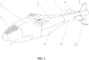
- a fairing assembly which includes an unmanned aerial vehicle shield body arranged symmetrically and a tail, the tail includes a horizontal stabilizer 8, an upper vertical fin 9 and a lower vertical fin 10.
- the unmanned aerial vehicle shield body includes a front section shield body 1, a middle front section shield body 3, a middle rear section shield body and a tail section shield body, where the middle rear section shield body includes a middle rear upper shield body 5 and a middle rear lower shield body 4, the tail section shield body includes a tail section left shield body 6 and a tail section right shield body 7. Two adjacent shield bodies are detachably connected.
- the number of the horizontal stabilizer is two, and a first through hole for passing through the horizontal stabilizers 8 is provided on both side surfaces of the tail section left shield body 6 and the tail section right shield body 7.
- a second through hole for passing through the upper vertical fin 9 is provided on an upper junction of the tail section left shield body 6 and the tail section right shield body 7.
- a third through hole for passing through the lower vertical fin 10 is provided on a lower junction of the tail section left shield body 6 and the tail section right shield body 7.
- a fourth through hole for passing through a rotor shaft is provided on a junction of the middle rear upper shield body 5 and the middle front section shield body 3.
- the fairing assembly provided by the present application is a combination structure that is divided into multiple shield bodies by symmetrically arranging the unmanned aerial vehicle shield body, where two adjacent shields are detachably connected to each other.
- the first through hole for passing through the horizontal stabilizers 8 are provided on both side surfaces of the tail section left shield body 6 and the tail section right shield body 7. Therefore, the horizontal stabilizers 8 do not affect separate disassembly of the tail section left shield body 6 and the tail section right shield body 7.
- the second through hole for passing through the upper vertical fin 9 is provided on an upper junction of the tail section left shield body 6 and the tail section right shield body 7. Therefore, the upper vertical fin 9 does not affect separate disassembly of the tail section left shield body 6 and the tail section right shield body 7.
- the third through hole for passing through the lower vertical fin 10 is provided on a lower junction of the tail section left shield body 6 and the tail section right shield body 7. Therefore, the lower vertical fin 10 does not affect separate disassembly of the tail section left shield body 6 and the tail section right shield body 7. That is, the tail section left shield body 6 and the tail section right shield body 7 may both be separately disassembled from the unmanned aerial vehicle.
- the fourth through hole for passing through a rotor shaft is provided on a junction of the middle rear upper shield body 5 and the middle front section shield body 3. Therefore, the rotor shaft does not affect separate disassembly of the middle rear upper shield body 5 and the middle front section shield body 3.
- the middle rear upper shield body 5 and the middle front section shield body 3 may be directly disassembled from the unmanned aerial vehicle.
- the front section shield body 1 and the middle rear lower shield body 4 may be disassembled directly from the unmanned aerial vehicle. Therefore, multiple shield bodies of the unmanned aerial vehicle shield body (the front section shield body 1, the middle front section shield body 3, the middle rear upper shield body 5, the middle rear lower shield body 4, the tail section left shield body 6 and the tail section right shield body 7) may all be disassembled and assembled separately to avoid the operation of completely disassembling the unmanned aerial vehicle shield body during ground maintenance.
- Corresponding shield bodies on the unmanned aerial vehicle shield body may be disassembled according to actual needs, so as to perform repair operations on internal parts of the unmanned aerial vehicle, and to separately disassemble and replace the corresponding shield bodies after the unmanned aerial vehicle shield body is partially damaged.
- the corresponding shield bodies By separately disassembling and assembling the corresponding shield bodies, an integral disassembly and assembly operation of the unmanned aerial vehicle shield body is effectively avoided, and the ground maintenance time is effectively shortened.
- the above direction is a direction of the unmanned aerial vehicle during normal flight or placement.
- Various devices and parts of the unmanned aerial vehicle are wrapped in the fairing assembly.
- the number of the fourth through hole is two, and the fourth through holes are round holes.
- two fourth through holes respectively pass through two rotor shafts of the unmanned aerial vehicle.
- hole boundaries of the first through hole, the second through hole, and the third through hole adopt a sandwich form to enhance the strength and rigidity of the through holes.
- Each shield body of the unmanned aerial vehicle shield body is composed of glass fiber and an aramid honeycomb core, which is relatively light in weight.
- Reasonable division of the unmanned aerial vehicle shield body ensures good accessibility and reasonable connection structure of a part to be repaired, which is conducive to disassembly and assembly.
- Side surfaces of the fairing assembly have a streamlined shape, which are formed by lofting out several trapezoids with rounded corners and narrow lower parts.
- an edge of one of the two adjacent shield bodies has a step surface, and an edge of the other shield body is overlapped with and connected to the step surface; outer surfaces of the two adjacent shield bodies are in smooth transition at the junction.
- the above smooth transition means that an end surface of junction without the shield body is exposed, so that when wind flows along an outer surface of one shield body to an outer surface of the other shield body, it may not be obstructed by the end surface.
- an edge of the front section shield body 1 is overlapped with and connected to an edge of the middle front section shield body 3.
- the edge of the front section shield body 1 has a first step surface 11, a connecting edge 31 of the middle front section shield body 3, which faces toward the front section shield body 1, is overlapped with and connected to the front section shield body 1 on the first step surface 11.
- outer surfaces of the front section shield body 1 and the middle front section shield body 3 are in a smooth transition at the junction.
- an edge of the middle front section shield body 3, which faces toward the middle rear upper shield body 5, has a second step surface 32. Therefore, an edge of the middle rear upper shield body 5, which faces toward the middle front section shield body 3, is overlapped with and connected to the middle front section shield body 3 on the second step surface 32.
- outer surfaces of the middle rear upper shield body 5 and the middle front section shield body 3 are in a smooth transition at the junction.
- an edge of the middle rear lower shield body 4, which faces toward the middle rear upper shield body 5, has a third step surface 41. Therefore, an edge of the middle rear upper shield body 5, which faces toward the middle rear lower shield body 4, is overlapped with and connected to the middle rear lower shield body 4 on the third step surface 41.
- outer surfaces of the middle rear upper shield body 5 and the middle rear lower shield body 4 are in a smooth transition at the junction.
- an edge of the tail section left shield body 6, which faces toward the middle rear section shield body has a fourth step surface 61
- an edge of the tail section right shield body 7 which faces toward the middle rear section shield body has a fifth step surface 71. Therefore, edges of the middle rear section shield bodies, which face toward the tail section shield bodies, are overlapped with and connected to the tail section shield bodies on the fourth step surface 61 and the fifth step surface 71.
- the first step surface 11, the second step surface 32, the third step surface 41, the fourth step surface 61, and the fifth step surface 71 are caved in at outer curved surfaces to form an inner notch. That is, a connecting strake of shield body edge is caved in by a certain height, so that the caved part and other sections of the shield body outer surface form a step surface, where a height difference of the caved part only needs to be equivalent to a thickness of a fairing to be connected. That is, a cross section of an edge where the step surface is provided is a "Z" shape, which has desirable rigidity.
- the fairing assembly has a streamlined curved surface structure to further reduce the wind resistance of the unmanned aerial vehicle during traveling.
- the junction of the two adjacent shield bodies is connected by a bolt successively passing through the edge of one of the two adjacent shield bodies and the edge of the other shield body. It is convenient to disassemble and assemble the shield body by disassembling and assembling bolt. Of course, a corresponding buckle structure may also be provided, which will not be described herein and are all within the protection scope.
- the bolts are quick-release bolts to further improve the disassembly efficiency.
- the implementation of other types of bolt is not excluded, which will not be described in detail herein.
- a ventilation grid 2 is provided on the front section shield body 1, and a bottom of the unmanned aerial vehicle body has a hollow structure.
- multiple grids are linearly arranged on the ventilation grid 2, and a width of the grid is smaller than a separation distance between two adjacent grids.
- a shape and size of the hollow structure of the grid may be designed according to actual conditions, and is not limited to the form in the present application.
- a side edge of the middle rear lower shield body 4, which faces toward the middle front section shield body 3, has a notch structure; the middle rear lower shield body 4 and the middle front section shield body 3 are connected to each other to form the hollow structure.
- the hollow structure may also be provided in other positions, which will not be described herein.
- air is blown in through the ventilation grid 2 and blown out through the hollow structure below the unmanned aerial vehicle shield body, which is beneficial for the heating part to exchange heat with air outside the unmanned aerial vehicle shield body.
- the horizontal stabilizer 8 includes a frame 81, a tubular beam 82 and a horizontal stabilizer panel 83.
- the number of the frame 81 is at least two, and the two frames 81 are arranged along an axial direction of the tubular beam 82.
- the horizontal stabilizer panel 83 is provided outside the frame 81.
- the number of the tubular beam 82 is at least two, all the tubular beams 82 is connected to the same frame 81.
- the horizontal stabilizers 8 are mounted and fixed on a fuselage of an unmanned aerial vehicle through the tubular beams 82. Since at least two tubular beams 82 are both connected to the frame 81, a connection effect between the frame 81 and the tubular beams 82 is effectively improved.
- the number of frame 81 is four, the frames are evenly distributed along the axial direction of the tubular beams 82.
- each of the frames 81 is perpendicular to each of the tubular beams 82.
- the frames 81 are mainly configured to bear the aerodynamic load and vibration generated by the horizontal stabilizers 8 during the flight process; the horizontal stabilizer panel 83 plays the role of enveloping, maintaining the shape and aerodynamic smoothing; the horizontal stabilizers 8 adopt a cantilever beam structure with fixed roots.
- the tubular beams 82 are carbon fiber pipes.
- the frames 81 are aluminum alloy frames, which effectively reduce the weight on the basis of ensuring the support strength.
- the horizontal stabilizer panel 83 is made of glass fiber and an aramid honeycomb core, which effectively improves the strength.
- the number of the tubular beam is two, which are respectively a first tubular beam and a second tubular beam, and a diameter of the first tubular beam is greater than a diameter of the second tubular beam; the first tubular beam is arranged at a position on the horizontal stabilizer where a horizontal stabilizer airfoil has the maximum thickness, and the second tubular beam is arranged at an area of 50% to 60% of a wing chord.
- a wing chord is a line connecting a leading edge point and a trailing edge point of the airfoil, and the area of 50% ⁇ 60% of a wing chord is an area from the middle position (50%) of the wing chord to the 60% position of the wing chord.
- a chord length is 320 mm.
- a diameter of the tubular beams 82 is 60% of the airfoil thickness.
- the diameter of the tubular beams 82 may also be set to other sizes.
- an airfoil selected for the horizontal stabilizers 8 is NACA4412.
- the upper vertical fin 9 includes a longitudinal beam 91, a transverse rib 92 and an upper vertical fin panel 93; the number of the transverse rib 92 is at least two, which are arranged along an extending direction of the longitudinal beams 91; the upper vertical fin panel 93 is provided outside the transverse ribs 92; the transverse ribs 92 are connected to the longitudinal beam 91; the upper vertical fin 9 passes through the second through hole and is connected to a fuselage of an unmanned aerial vehicle. It is understandable that due to structural limitations of the upper vertical fin 9, structures of the two transverse ribs 92 are different, and total sizes thereof decrease in a direction away from the fuselage of the unmanned aerial vehicle.
- the number of longitudinal beam 91 is two, and since at least total sizes of the transverse ribs decrease in a direction away from the fuselage of the unmanned aerial vehicle, a certain angle is formed between the two longitudinal beams 91.
- One longitudinal beam 91 or three longitudinal beams 91 may also be provided, which will not be described one by one herein and are all within the protection scope.
- the longitudinal beams 91 are aluminum square pipe profiles, which may also be set to other profiles or other structures.
- each of the longitudinal beams 91 and each of the transverse ribs 92 are fixedly connected by bolt, which may also be connected by welding or gluing.
- the upper vertical fin 9 is mounted on and fixed to the fuselage by bolt, the upper vertical fin 9 may also be directly welded to the fuselage.
- the lower vertical fin 10 includes a lower vertical fin longitudinal beam 101, a lower vertical fin transverse rib 102, a pipe frame 103, and a tail skid 104 and a lower vertical fin panel 105;
- the number of the lower vertical fin longitudinal beam 101 is two, and a lower end of one of the lower vertical fin longitudinal beams 101 is supported on the other lower vertical fin longitudinal beam 101 by the pipe frame 103;
- the number of the lower vertical fin transverse rib 102 is at least two, which are arranged along extending directions of the lower vertical fin longitudinal beams 101;
- the tail skid 104 is connected to the lower vertical fin transverse rib 102 located at a lowermost end of the lower vertical fin 10;
- the lower vertical fin 10 passes through the third through hole and is connected to a fuselage of a unmanned aerial vehicle.
- the lower vertical fin 10 is mounted on and fixed to the fuselage by bolt.
- one of the lower vertical fin longitudinal beams 101 is an aluminum square pipe profile, and the other lower vertical fin longitudinal beam 101 is an aluminum bar profile.
- each of the lower vertical fin longitudinal beams 101 is fixedly connected to each of the lower vertical fin transverse ribs 102 by bolt, which may also be connected by welding or gluing.
- tail skid 104 is fixedly connected to the lower vertical fin transverse rib 102 by bolt, which may also be directly provided at an end, a lower end of which away from the fuselage through the pipe frame 103.
- An intermeshing dual-rotor unmanned helicopter is further provided according to the present application, which includes a fairing assembly, where the fairing assembly is any fairing assembly described above. Since the above fairing assembly has the above technical effects, the intermeshing dual-rotor unmanned helicopter with the above fairing assembly may also have the same technical effects, which will not be described herein.
Landscapes
- Engineering & Computer Science (AREA)
- Aviation & Aerospace Engineering (AREA)
- Mechanical Engineering (AREA)
- Remote Sensing (AREA)
- Manufacturing & Machinery (AREA)
- Transportation (AREA)
- Health & Medical Sciences (AREA)
- General Health & Medical Sciences (AREA)
- Pulmonology (AREA)
- Body Structure For Vehicles (AREA)
- Lining And Supports For Tunnels (AREA)
- Aiming, Guidance, Guns With A Light Source, Armor, Camouflage, And Targets (AREA)
Description
- The present application relates to the technical field of helicopters, in particular to an intermeshing dual-rotor unmanned helicopter and a fairing assembly.
- In the conventional technology, a fairing is an indispensable part of an unmanned aerial vehicle. The fairing is mounted outside the airframe and covers the entire unmanned aerial vehicle, which has functions of shaping and maintaining an aerodynamic shape. The cross-dual-rotor composite thrust tail rotor unmanned helicopter developed by Tsinghua University and manufactured by Fujian Qinghang Equipment Technology Co., Ltd., is an example of an intermeshing dual-rotor unmanned helicopter. It comprises multiples fairing panels, two intermeshing rotors, two horizontal tail fins, an upper vertical tail fin and a lower vertical tail fin.
- Due to the fast flight speed, the fairing may produce a big air resistance, so a shape of the fairing needs to consider a characteristic of the unmanned aerial vehicle, which is a pursuit for the minimum wind resistance. However, the unmanned aerial vehicle needs to be completely disassembled and reassembled during ground maintenance. In order to shorten ground inspection and maintenance time of the various devices and parts under the unmanned aerial vehicle fairing, the fairing may adopt a detachable connection.
- In view of this, a technical issue to be urgently addressed by those skilled in the art is to shorten a ground maintenance time of devices under the fairing.
- An object of the present application is to provide a fairing assembly to shorten the ground maintenance time of devices under the fairing. An intermeshing dual-rotor unmanned helicopter is further provided according to the present application.
- In order to solve the above technical problem, a fairing assembly is provided according to the present application, which includes an unmanned aerial vehicle shield body arranged symmetrically and a tail, the tail comprising horizontal stabilizers, an upper vertical fin and a lower vertical fin;
- the unmanned aerial vehicle shield body comprises a front section shield body, a middle front section shield body, a middle rear section shield body and a tail section shield body, the middle rear section shield body comprises a middle rear upper shield body and a middle rear lower shield body, the tail section shield body comprises a tail section left shield body and a tail section right shield body; two adjacent shield bodies are detachably connected;
- the number of the horizontal stabilizers is two, and a first through hole for passing through the horizontal stabilizer is provided on a side surface of each of the tail section left shield body and the tail section right shield body, so that the horizontal stabilizer does not affect separate disassembly of the tail section left shield body and the tail section right shield body;
- a second through hole for passing through the upper vertical fin is provided on an upper junction of each of the tail section left shield body and the tail section right shield body, so that the upper vertical fin does not affect separate disassembly of the tail section left shield body and the tail section right shield body; a third through hole for passing through the lower vertical fin is provided on a lower junction of each of the tail section left shield body and the tail section right shield body, so that the lower vertical fin does not affect separate disassembly of the tail section left shield body and the tail section right shield body;
- a fourth through hole for passing through a rotor shaft is provided on a junction of the middle rear upper shield body and the middle front section shield body, so that the rotor shaft does not affect separate disassembly of the middle rear upper shield body and the middle front section shield body,
- at a junction of two adjacent shield bodies, an edge of one of the two adjacent shield bodies has a step surface, and an edge of the other of the two adjacent shield bodies is overlapped with and connected to the step surface,
- outer surfaces of the two adjacent shield bodies are in smooth transition at the junction.
- In an embodiment, the junction of the two adjacent shield bodies is connected by a bolt successively passing through the edge of one of the two adjacent shield bodies and the edge of the other of the two adjacent shield bodies.
- In an embodiment, the bolt is a quick-release bolt.
- In an embodiment, a ventilation grid is provided on the front section shield body, and a bottom of the unmanned aerial vehicle body has a hollow structure;
when an unmanned aerial vehicle travels, air enters the unmanned aerial vehicle body through the ventilation grid and flows out of the hollow structure. - In an embodiment, a side edge of the middle rear lower shield body, which faces toward the middle front section shield body, has a notch structure;
the middle rear lower shield body and the middle front section shield body are connected to each other to form the hollow structure. - In an embodiment, the horizontal stabilizer comprises frames, tubular beams and a horizontal stabilizer panel;
- the number of the frames is at least two, and the frames are arranged along an axial direction of the tubular beam;
- the horizontal stabilizer panel is provided outside the frames;
- the number of the tubular beams is at least two, all the tubular beams are connected to the same frame;
- the horizontal stabilizers are mounted and fixed on the unmanned aerial vehicle shield body of an unmanned aerial vehicle through the tubular beams.
- In an embodiment, the tubular beams are carbon fiber pipes;
- and/or, the frames are aluminum alloy frames;
- and/or, the horizontal stabilizer panel is made of glass fiber and an aramid honeycomb core;
- and/or, gaps between the frames and the horizontal stabilizer panel are filled with foam.
- In an embodiment, the number of the tubular beams is two, the tubular beams are respectively a first tubular beam and a second tubular beam, and a diameter of the first tubular beam is greater than a diameter of the second tubular beam;
the first tubular beam is arranged at a position on the horizontal stabilizer where a horizontal stabilizer airfoil has the maximum thickness, and the second tubular beam is arranged at an area of 50% to 60% of a wing chord. - In an embodiment, the upper vertical fin comprises a longitudinal beam, transverse ribs and an upper vertical fin panel ;
- the number of the transverse rib is at least two, which are arranged along an extending direction of the longitudinal beam;
- the upper vertical fin panel is provided outside the transverse ribs ;
- each of the transverse ribs is connected to the longitudinal beam ;
- the upper vertical fin passes through the second through hole and is connected to the unmanned aerial vehicle shield body of an unmanned aerial vehicle.
- In an embodiment, the longitudinal beam is an aluminum square pipe profile;
- and/or, the longitudinal beam is fixed to and connected to each of the transverse ribs by bolt;
- and/or, the upper vertical fin is mounted on and fixed to the unmanned aerial vehicle shield body by bolt.
- In an embodiment, the lower vertical fin comprises lower vertical fin longitudinal beams, lower vertical fin transverse ribs, a pipe frame, and a tail skid and a lower vertical fin panel;
- the number of the lower vertical fin longitudinal beams is two, and a lower end of one of the lower vertical fin longitudinal beams is supported on the other of the lower vertical fin longitudinal beam by the pipe frame;
- the number of the lower vertical fin transverse rib is at least two, which are arranged along extending directions of the lower vertical fin longitudinal beams;
- the tail skid is connected to the lower vertical fin transverse rib located at a bottom of the lower vertical fin ;
- the lower vertical fin passes through the third through hole and is connected to the unmanned aerial vehicle shield body of an unmanned aerial vehicle.
- In an embodiment, the lower vertical fin is mounted on and fixed to the unmanned aerial vehicle shield body by bolt;
- and/or, one of the lower vertical fin longitudinal beams is an aluminum square pipe profile, and the other of the lower vertical fin longitudinal beam is an aluminum bar profile;
- and/or, each of the lower vertical fin longitudinal beams is fixedly connected to each of the lower vertical fin transverse ribs by bolt;
- and/or, the tail skid is fixedly connected to the lower vertical fin transverse rib by bolt.
- An intermeshing dual-rotor unmanned helicopter is further provided according to the present application, which includes a fairing assembly, where the fairing assembly is the fairing assembly.
- The fairing assembly provided by the present application is a combination structure that may be divided into multiple shield bodies by symmetrically arranging the unmanned aerial vehicle shield body, where two adjacent shields may be detachably connected to each other. A first through hole for passing through horizontal stabilizers is provided on both side surfaces of the tail section left shield body and the tail section right shield body. Therefore, the horizontal stabilizers do not affect separate disassembly of the tail section left shield body and the tail section right shield body. A second through hole for passing through the upper vertical fin is provided on an upper junction of the tail section left shield body and the tail section right shield body. Therefore, the upper vertical fin does not affect separate disassembly of the tail section left shield body and the tail section right shield body. A third through hole for passing through the lower vertical fin is provided on a lower junction of the tail section left shield body and the tail section right shield body. Therefore, the lower vertical fin does not affect separate disassembly of the tail section left shield body and the tail section right shield body. That is, the tail section left shield body and the tail section right shield body may both be separately disassembled from the unmanned aerial vehicle. A fourth through hole for passing through a rotor shaft is provided on a junction of the middle rear upper shield body and the middle front section shield body. Therefore, the rotor shaft does not affect separate disassembly of the middle rear upper shield body and the middle front section shield body. That is, the middle rear upper shield body and the middle front section shield body may be directly disassembled from the unmanned aerial vehicle. In addition, the front section shield body and the middle rear lower shield body may be disassembled directly from the unmanned aerial vehicle. Therefore, multiple shield bodies of the unmanned aerial vehicle shield body (the front section shield body, the middle front section shield body, the middle rear upper shield body, the middle rear lower shield body, the tail section left shield body and the tail section right shield body) may all be disassembled and assembled separately to avoid the operation of completely disassembling the unmanned aerial vehicle shield body during ground maintenance. Corresponding shield bodies on the unmanned aerial vehicle shield body (i.e., the front section shield body, the middle front section shield body, the middle rear upper shield body, the middle rear lower shield body, the tail section left shield body or the tail section right shield body) may be disassembled according to actual needs, so as to perform repair operations on internal parts of the unmanned aerial vehicle, and to separately disassemble and replace the corresponding shield bodies after the unmanned aerial vehicle shield body is partially damaged. By separately disassembling and assembling the corresponding shield bodies, an integral disassembly and assembly operation of the unmanned aerial vehicle shield body is effectively avoided, and the ground maintenance time is effectively shortened.
- An intermeshing dual-rotor unmanned helicopter is further provided according to the present application, which includes a fairing assembly, where the fairing assembly is any fairing assembly described above. Since the above fairing assembly has the above technical effects, the intermeshing dual-rotor unmanned helicopter with the above fairing assembly may also have the same technical effects, which will not be described herein.
-
-
FIG. 1 is a structural schematic diagram of a fairing assembly provided by the present application; -
FIG. 2 is a structural schematic diagram of a front section shield body and a middle front section shield body provided by the present application; -
FIG. 3 is a partial enlarged schematic diagram of part A inFIG. 2 ; -
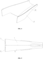
FIG. 4 is a structural schematic diagram of a middle rear lower shield body provided by the present application; -
FIG. 5 is a structural schematic diagram of a tail section shield body provided by the present application; -
FIG. 6 is a structural schematic diagram of a horizontal stabilizer provided by the present application; -
FIG. 7 is a structural schematic diagram of an upper vertical fin provided by the present application; -
FIG. 8 is a structural schematic diagram of a lower vertical fin provided by the present application; - A core of the present application is to provide a fairing assembly to shorten the ground maintenance time of devices under the fairing. An intermeshing dual-rotor unmanned helicopter is further provided according to the present application.
- In order to enable those skilled in the art to better understand technical solutions of the present application, the present application will be further described in detail below with reference to the accompanying drawings and specific embodiments.
- As shown in
FIG. 1 , a fairing assembly is provided according to an embodiment of the present application, which includes an unmanned aerial vehicle shield body arranged symmetrically and a tail, the tail includes a horizontal stabilizer 8, an upper vertical fin 9 and a lowervertical fin 10. The unmanned aerial vehicle shield body includes a front section shield body 1, a middle frontsection shield body 3, a middle rear section shield body and a tail section shield body, where the middle rear section shield body includes a middle rearupper shield body 5 and a middle rearlower shield body 4, the tail section shield body includes a tail section leftshield body 6 and a tail sectionright shield body 7. Two adjacent shield bodies are detachably connected. The number of the horizontal stabilizer is two, and a first through hole for passing through the horizontal stabilizers 8 is provided on both side surfaces of the tail section leftshield body 6 and the tail sectionright shield body 7. A second through hole for passing through the upper vertical fin 9 is provided on an upper junction of the tail section leftshield body 6 and the tail sectionright shield body 7. A third through hole for passing through the lowervertical fin 10 is provided on a lower junction of the tail section leftshield body 6 and the tail sectionright shield body 7. A fourth through hole for passing through a rotor shaft is provided on a junction of the middle rearupper shield body 5 and the middle frontsection shield body 3. - The fairing assembly provided by the present application is a combination structure that is divided into multiple shield bodies by symmetrically arranging the unmanned aerial vehicle shield body, where two adjacent shields are detachably connected to each other. The first through hole for passing through the horizontal stabilizers 8 are provided on both side surfaces of the tail section left
shield body 6 and the tail sectionright shield body 7. Therefore, the horizontal stabilizers 8 do not affect separate disassembly of the tail section leftshield body 6 and the tail sectionright shield body 7. The second through hole for passing through the upper vertical fin 9 is provided on an upper junction of the tail section leftshield body 6 and the tail sectionright shield body 7. Therefore, the upper vertical fin 9 does not affect separate disassembly of the tail section leftshield body 6 and the tail sectionright shield body 7. The third through hole for passing through the lowervertical fin 10 is provided on a lower junction of the tail section leftshield body 6 and the tail sectionright shield body 7. Therefore, the lowervertical fin 10 does not affect separate disassembly of the tail section leftshield body 6 and the tail sectionright shield body 7. That is, the tail section leftshield body 6 and the tail sectionright shield body 7 may both be separately disassembled from the unmanned aerial vehicle. The fourth through hole for passing through a rotor shaft is provided on a junction of the middle rearupper shield body 5 and the middle frontsection shield body 3. Therefore, the rotor shaft does not affect separate disassembly of the middle rearupper shield body 5 and the middle frontsection shield body 3. That is, the middle rearupper shield body 5 and the middle frontsection shield body 3 may be directly disassembled from the unmanned aerial vehicle. In addition, the front section shield body 1 and the middle rearlower shield body 4 may be disassembled directly from the unmanned aerial vehicle. Therefore, multiple shield bodies of the unmanned aerial vehicle shield body (the front section shield body 1, the middle frontsection shield body 3, the middle rearupper shield body 5, the middle rearlower shield body 4, the tail section leftshield body 6 and the tail section right shield body 7) may all be disassembled and assembled separately to avoid the operation of completely disassembling the unmanned aerial vehicle shield body during ground maintenance. Corresponding shield bodies on the unmanned aerial vehicle shield body (i.e., the front section shield body 1, the middle frontsection shield body 3, the middle rearupper shield body 5, the middle rearlower shield body 4, the tail section leftshield body 6 or the tail section right shield body 7) may be disassembled according to actual needs, so as to perform repair operations on internal parts of the unmanned aerial vehicle, and to separately disassemble and replace the corresponding shield bodies after the unmanned aerial vehicle shield body is partially damaged. By separately disassembling and assembling the corresponding shield bodies, an integral disassembly and assembly operation of the unmanned aerial vehicle shield body is effectively avoided, and the ground maintenance time is effectively shortened. - It is understandable that the above direction is a direction of the unmanned aerial vehicle during normal flight or placement. Various devices and parts of the unmanned aerial vehicle are wrapped in the fairing assembly. The number of the fourth through hole is two, and the fourth through holes are round holes. With the above arrangement, two fourth through holes respectively pass through two rotor shafts of the unmanned aerial vehicle. In addition, hole boundaries of the first through hole, the second through hole, and the third through hole adopt a sandwich form to enhance the strength and rigidity of the through holes.
- Each shield body of the unmanned aerial vehicle shield body is composed of glass fiber and an aramid honeycomb core, which is relatively light in weight. Reasonable division of the unmanned aerial vehicle shield body ensures good accessibility and reasonable connection structure of a part to be repaired, which is conducive to disassembly and assembly.
- Side surfaces of the fairing assembly have a streamlined shape, which are formed by lofting out several trapezoids with rounded corners and narrow lower parts.
- At a junction of two adjacent shield bodies, an edge of one of the two adjacent shield bodies has a step surface, and an edge of the other shield body is overlapped with and connected to the step surface; outer surfaces of the two adjacent shield bodies are in smooth transition at the junction. With the above arrangement, surfaces of the unmanned aerial vehicle shield body are smooth and connected to each other, which effectively reduces the wind resistance when the unmanned aerial vehicle travels.
- The above smooth transition means that an end surface of junction without the shield body is exposed, so that when wind flows along an outer surface of one shield body to an outer surface of the other shield body, it may not be obstructed by the end surface.
- As shown in
FIG. 1 to FIG. 3 , an edge of the front section shield body 1 is overlapped with and connected to an edge of the middle frontsection shield body 3. The edge of the front section shield body 1 has afirst step surface 11, a connectingedge 31 of the middle frontsection shield body 3, which faces toward the front section shield body 1, is overlapped with and connected to the front section shield body 1 on thefirst step surface 11. In addition, outer surfaces of the front section shield body 1 and the middle frontsection shield body 3 are in a smooth transition at the junction. - As shown in
FIG. 2 , an edge of the middle frontsection shield body 3, which faces toward the middle rearupper shield body 5, has asecond step surface 32. Therefore, an edge of the middle rearupper shield body 5, which faces toward the middle frontsection shield body 3, is overlapped with and connected to the middle frontsection shield body 3 on thesecond step surface 32. In addition, outer surfaces of the middle rearupper shield body 5 and the middle frontsection shield body 3 are in a smooth transition at the junction. - As shown in
FIG. 4 , an edge of the middle rearlower shield body 4, which faces toward the middle rearupper shield body 5, has athird step surface 41. Therefore, an edge of the middle rearupper shield body 5, which faces toward the middle rearlower shield body 4, is overlapped with and connected to the middle rearlower shield body 4 on thethird step surface 41. In addition, outer surfaces of the middle rearupper shield body 5 and the middle rearlower shield body 4 are in a smooth transition at the junction. - As shown in
FIG. 5 , an edge of the tail section leftshield body 6, which faces toward the middle rear section shield body, has afourth step surface 61, an edge of the tail sectionright shield body 7, which faces toward the middle rear section shield body, has afifth step surface 71. Therefore, edges of the middle rear section shield bodies, which face toward the tail section shield bodies, are overlapped with and connected to the tail section shield bodies on thefourth step surface 61 and thefifth step surface 71. - The
first step surface 11, thesecond step surface 32, thethird step surface 41, thefourth step surface 61, and thefifth step surface 71 are caved in at outer curved surfaces to form an inner notch. That is, a connecting strake of shield body edge is caved in by a certain height, so that the caved part and other sections of the shield body outer surface form a step surface, where a height difference of the caved part only needs to be equivalent to a thickness of a fairing to be connected. That is, a cross section of an edge where the step surface is provided is a "Z" shape, which has desirable rigidity. - Further, the fairing assembly has a streamlined curved surface structure to further reduce the wind resistance of the unmanned aerial vehicle during traveling.
- In this embodiment, the junction of the two adjacent shield bodies is connected by a bolt successively passing through the edge of one of the two adjacent shield bodies and the edge of the other shield body. It is convenient to disassemble and assemble the shield body by disassembling and assembling bolt. Of course, a corresponding buckle structure may also be provided, which will not be described herein and are all within the protection scope.
- The bolts are quick-release bolts to further improve the disassembly efficiency. The implementation of other types of bolt is not excluded, which will not be described in detail herein.
- In this embodiment, a
ventilation grid 2 is provided on the front section shield body 1, and a bottom of the unmanned aerial vehicle body has a hollow structure. When the unmanned aerial vehicle travels, air enters the unmanned aerial vehicle body through the ventilation grid and flows out of the hollow structure. With the above arrangement, flowing air is formed inside the fairing assembly, which is beneficial to the heat dissipation of internal devices and parts of the unmanned aerial vehicle. - In this embodiment, multiple grids are linearly arranged on the
ventilation grid 2, and a width of the grid is smaller than a separation distance between two adjacent grids. Specifically, a shape and size of the hollow structure of the grid may be designed according to actual conditions, and is not limited to the form in the present application. - As shown in
FIG. 4 , a side edge of the middle rearlower shield body 4, which faces toward the middle frontsection shield body 3, has a notch structure; the middle rearlower shield body 4 and the middle frontsection shield body 3 are connected to each other to form the hollow structure. The hollow structure may also be provided in other positions, which will not be described herein. - There is at least one heating part below the
ventilation grid 2. When the unmanned aerial vehicle travels, air is blown in through theventilation grid 2 and blown out through the hollow structure below the unmanned aerial vehicle shield body, which is beneficial for the heating part to exchange heat with air outside the unmanned aerial vehicle shield body. - As shown in
FIG. 6 , the horizontal stabilizer 8 includes aframe 81, atubular beam 82 and ahorizontal stabilizer panel 83. The number of theframe 81 is at least two, and the twoframes 81 are arranged along an axial direction of thetubular beam 82. Thehorizontal stabilizer panel 83 is provided outside theframe 81. The number of thetubular beam 82 is at least two, all thetubular beams 82 is connected to thesame frame 81. The horizontal stabilizers 8 are mounted and fixed on a fuselage of an unmanned aerial vehicle through the tubular beams 82. Since at least twotubular beams 82 are both connected to theframe 81, a connection effect between theframe 81 and thetubular beams 82 is effectively improved. In this embodiment, the number offrame 81 is four, the frames are evenly distributed along the axial direction of the tubular beams 82. In addition, each of theframes 81 is perpendicular to each of the tubular beams 82. Theframes 81 are mainly configured to bear the aerodynamic load and vibration generated by the horizontal stabilizers 8 during the flight process; thehorizontal stabilizer panel 83 plays the role of enveloping, maintaining the shape and aerodynamic smoothing; the horizontal stabilizers 8 adopt a cantilever beam structure with fixed roots. - In order to reduce the weight, the
tubular beams 82 are carbon fiber pipes. - In this embodiment, the
frames 81 are aluminum alloy frames, which effectively reduce the weight on the basis of ensuring the support strength. - Furthermore, the
horizontal stabilizer panel 83 is made of glass fiber and an aramid honeycomb core, which effectively improves the strength. - In order to improve the connection stability, gaps between the
frames 81 and thetail panel 83 are filled with foam. With the above arrangement, on the basis of ensuring the connection strength, the weight is reduced as much as possible. - In this embodiment, the number of the tubular beam is two, which are respectively a first tubular beam and a second tubular beam, and a diameter of the first tubular beam is greater than a diameter of the second tubular beam; the first tubular beam is arranged at a position on the horizontal stabilizer where a horizontal stabilizer airfoil has the maximum thickness, and the second tubular beam is arranged at an area of 50% to 60% of a wing chord. A wing chord is a line connecting a leading edge point and a trailing edge point of the airfoil, and the area of 50%~60% of a wing chord is an area from the middle position (50%) of the wing chord to the 60% position of the wing chord. In this embodiment, a chord length is 320 mm.
- Further, for the dual consideration of improving the support stability and reducing the total weight, a diameter of the
tubular beams 82 is 60% of the airfoil thickness. Of course, the diameter of thetubular beams 82 may also be set to other sizes. - In this embodiment, an airfoil selected for the horizontal stabilizers 8 is NACA4412.
- As shown in
FIG. 7 , the upper vertical fin 9 includes alongitudinal beam 91, atransverse rib 92 and an uppervertical fin panel 93; the number of thetransverse rib 92 is at least two, which are arranged along an extending direction of thelongitudinal beams 91; the uppervertical fin panel 93 is provided outside thetransverse ribs 92; thetransverse ribs 92 are connected to thelongitudinal beam 91; the upper vertical fin 9 passes through the second through hole and is connected to a fuselage of an unmanned aerial vehicle. It is understandable that due to structural limitations of the upper vertical fin 9, structures of the twotransverse ribs 92 are different, and total sizes thereof decrease in a direction away from the fuselage of the unmanned aerial vehicle. With the above arrangement, the structural stability of the upper vertical fin 9 is effectively improved. In this embodiment, the number oflongitudinal beam 91 is two, and since at least total sizes of the transverse ribs decrease in a direction away from the fuselage of the unmanned aerial vehicle, a certain angle is formed between the twolongitudinal beams 91. Onelongitudinal beam 91 or threelongitudinal beams 91 may also be provided, which will not be described one by one herein and are all within the protection scope. - In consideration of weight reduction, the
longitudinal beams 91 are aluminum square pipe profiles, which may also be set to other profiles or other structures. - Further, each of the
longitudinal beams 91 and each of thetransverse ribs 92 are fixedly connected by bolt, which may also be connected by welding or gluing. - Further, the upper vertical fin 9 is mounted on and fixed to the fuselage by bolt, the upper vertical fin 9 may also be directly welded to the fuselage.
- As shown in
FIG. 8 , the lowervertical fin 10 includes a lower vertical finlongitudinal beam 101, a lower vertical fintransverse rib 102, apipe frame 103, and atail skid 104 and a lowervertical fin panel 105; the number of the lower vertical finlongitudinal beam 101 is two, and a lower end of one of the lower vertical finlongitudinal beams 101 is supported on the other lower vertical finlongitudinal beam 101 by thepipe frame 103; the number of the lower vertical fintransverse rib 102 is at least two, which are arranged along extending directions of the lower vertical finlongitudinal beams 101; thetail skid 104 is connected to the lower vertical fintransverse rib 102 located at a lowermost end of the lowervertical fin 10; the lowervertical fin 10 passes through the third through hole and is connected to a fuselage of a unmanned aerial vehicle. With the above arrangement, the structural strength is effectively improved. - It is understandable that due to structural limitations of the lower
vertical fin 10, structures of at least two lower vertical fin transverse ribs are different, and total sizes thereof decrease in a direction away from the fuselage of the unmanned aerial vehicle. - In this embodiment, the lower
vertical fin 10 is mounted on and fixed to the fuselage by bolt. - For the convenience of installation, one of the lower vertical fin
longitudinal beams 101 is an aluminum square pipe profile, and the other lower vertical finlongitudinal beam 101 is an aluminum bar profile. - In this embodiment, each of the lower vertical fin
longitudinal beams 101 is fixedly connected to each of the lower vertical fintransverse ribs 102 by bolt, which may also be connected by welding or gluing. - Further, the
tail skid 104 is fixedly connected to the lower vertical fintransverse rib 102 by bolt, which may also be directly provided at an end, a lower end of which away from the fuselage through thepipe frame 103. - An intermeshing dual-rotor unmanned helicopter is further provided according to the present application, which includes a fairing assembly, where the fairing assembly is any fairing assembly described above. Since the above fairing assembly has the above technical effects, the intermeshing dual-rotor unmanned helicopter with the above fairing assembly may also have the same technical effects, which will not be described herein.
- The fairing assembly provided by the present application is introduced above in detail. Specific examples are used herein to illustrate the principle and implementation of the present application. The description of the above embodiments is only used to help to understand the method and core idea of the present application. It should be noted that for those of ordinary skill in the art, various improvements and modifications may be made to the present application without departing from the scope of the present application, and these improvements and modifications fall within the protection scope of claims of the present application.
1-front section shield body, 2-ventilation grid, 3-middle front section shield body, 4-middle rear lower shield body, 5-middle rear upper shield body, 6-tail section left shield body, 7-tail section right shield body, 8-horizontal stabilizer, 9-upper vertical fin, 10-lower vertical fin, 11-first step surface, 31- connecting edge of front section shield body and middle front section shield body, 32-second step surface, 41-third step surface, 61-fourth step surface, 71-fifth step surface, 81-frame, 82-tubular beam, 83-horizontal stabilizer panel, 91-longitudinal beam, 92-transverse rib, 93-upper vertical fin panel, 101-lower vertical fin longitudinal beam, 102-lower vertical fin transverse rib, 103-pipe frame, 104-tail skid, 105- lower vertical fin panel.
Claims (13)
- A fairing assembly, comprising an unmanned aerial vehicle shield body arranged symmetrically and a tail, the tail comprising horizontal stabilizers (8), an upper vertical fin (9) and a lower vertical fin (10);wherein the unmanned aerial vehicle shield body comprises a front section shield body (1), a middle front section shield body (3), a middle rear section shield body and a tail section shield body, wherein the middle rear section shield body comprises a middle rear upper shield body (5) and a middle rear lower shield body (4), the tail section shield body comprises a tail section left shield body (6) and a tail section right shield body (7); wherein two adjacent shield bodies are detachably connected;wherein the number of the horizontal stabilizers (8) is two, and a first through hole for passing through the horizontal stabilizer (8) is provided on a side surface of each of the tail section left shield body (6) and the tail section right shield body (7), so that the horizontal stabilizer (8) does not affect separate disassembly of the tail section left shield body (6) and the tail section right shield body (7);wherein a second through hole for passing through the upper vertical fin (9) is provided on an upper junction of each of the tail section left shield body (6) and the tail section right shield body (7), so that the upper vertical fin (9) does not affect separate disassembly of the tail section left shield body (6) and the tail section right shield body (7); wherein a third through hole for passing through the lower vertical fin (10) is provided on a lower junction of each of the tail section left shield body (6) and the tail section right shield body (7), so that the lower vertical fin (10) does not affect separate disassembly of the tail section left shield body (6) and the tail section right shield body (7);wherein a fourth through hole for passing through a rotor shaft is provided on a junction of the middle rear upper shield body (5) and the middle front section shield body (3), so that the rotor shaft does not affect separate disassembly of the middle rear upper shield body (5) and the middle front section shield body (3),wherein at a junction of two adjacent shield bodies, an edge of one of the two adjacent shield bodies has a step surface, and an edge of the other of the two adjacent shield bodies is overlapped with and connected to the step surface,wherein outer surfaces of the two adjacent shield bodies are in smooth transition at the junction.
- The fairing assembly according to claim 1, wherein the junction of the two adjacent shield bodies is connected by a bolt successively passing through the edge of one of the two adjacent shield bodies and the edge of the other of the two adjacent shield bodies.
- The fairing assembly of claim 2, wherein the bolt is a quick-release bolt.
- The fairing assembly according to claim 1, wherein a ventilation grid (2) is provided on the front section shield body (1), and a bottom of the unmanned aerial vehicle body has a hollow structure;
when an unmanned aerial vehicle travels, air enters the unmanned aerial vehicle body through the ventilation grid (2) and flows out of the hollow structure. - The fairing assembly according to claim 4, wherein a side edge of the middle rear lower shield body (4), which faces toward the middle front section shield body (3), has a notch structure;
wherein the middle rear lower shield body (4) and the middle front section shield body (3) are connected to each other to form the hollow structure. - The fairing assembly according to claim 1, wherein the horizontal stabilizer (8) comprises frames (81), tubular beams (82) and a horizontal stabilizer panel (83);wherein the number of the frames (81) is at least two, and the frames (81) are arranged along an axial direction of the tubular beam (82);wherein the horizontal stabilizer panel (83) is provided outside the frames (81);wherein the number of the tubular beams (82) is at least two, all the tubular beams (82) are connected to the same frame (81);wherein the horizontal stabilizers (8) are configured to be mounted and fixed on a fuselage of an unmanned aerial vehicle through the tubular beams (82).
- The fairing assembly according to claim 6, wherein the tubular beams (82) are carbon fiber pipes;and/or, the frames (81) are aluminum alloy frames;and/or, the horizontal stabilizer panel (83) is made of glass fiber and an aramid honeycomb core;and/or, gaps between the frames (81) and the horizontal stabilizer panel (83) are filled with foam.
- The fairing assembly according to claim 6 or 7, wherein the number of the tubular beams (82) is two, the tubular beams are respectively a first tubular beam and a second tubular beam, and a diameter of the first tubular beam is greater than a diameter of the second tubular beam;
wherein the first tubular beam is arranged at a position on the horizontal stabilizer (8) where a horizontal stabilizer airfoil has the maximum thickness, and the second tubular beam is arranged at an area of 50% to 60% of a wing chord. - The fairing assembly according to claim 1, wherein the upper vertical fin (9) comprises a longitudinal beam (91), transverse ribs (92) and an upper vertical fin panel (93);wherein the number of the transverse rib (92) is at least two, which are arranged along an extending direction of the longitudinal beam (91);(92); wherein the upper vertical fin panel (93) is provided outside the transverse ribswherein each of the transverse ribs (92) is connected to the longitudinal beam (91);wherein the upper vertical fin (9) passes through the second through hole and is configured to be connected to a fuselage of an unmanned aerial vehicle.
- The fairing assembly according to claim 9, wherein the longitudinal beam (91) is an aluminum square pipe profile;and/or, the longitudinal beam (91) is fixed to and connected to each of the transverse ribs (92) by bolt;and/or, the upper vertical fin (9) is configured to be mounted on and fixed to the fuselage by bolt.
- The fairing assembly according to claim 1, wherein the lower vertical fin (10) comprises lower vertical fin longitudinal beams (101), lower vertical fin transverse ribs (102), a pipe frame (103), and a tail skid (104) and a lower vertical fin panel (105);wherein the number of the lower vertical fin longitudinal beams (101) is two, and a lower end of one of the lower vertical fin longitudinal beams (101) is supported on the other of the lower vertical fin longitudinal beam (101) by the pipe frame (103);wherein the number of the lower vertical fin transverse rib (102) is at least two, which are arranged along extending directions of the lower vertical fin longitudinal beams (101);wherein the tail skid (104) is connected to the lower vertical fin transverse rib (102) located at a bottom of the lower vertical fin (10);wherein the lower vertical fin (10) passes through the third through hole and is configured to be connected to a fuselage of an unmanned aerial vehicle.
- The fairing assembly according to claim 11, wherein the lower vertical fin (10) is configured to be mounted on and fixed to the fuselage by bolt;and/or, one of the lower vertical fin longitudinal beams (101) is an aluminum square pipe profile, and the other of the lower vertical fin longitudinal beam (101) is an aluminum bar profile;and/or, each of the lower vertical fin longitudinal beams (101) is fixedly connected to each of the lower vertical fin transverse ribs (102) by bolt;and/or, the tail skid (104) is fixedly connected to the lower vertical fin transverse rib (102) by bolt.
- An intermeshing dual-rotor unmanned helicopter, comprising the fairing assembly according to any one of claims 1 to 12.
Applications Claiming Priority (1)
| Application Number | Priority Date | Filing Date | Title |
|---|---|---|---|
| CN202011188391.6A CN112093041B (en) | 2020-10-30 | 2020-10-30 | Cross double-rotor unmanned helicopter and fairing assembly thereof |
Publications (3)
| Publication Number | Publication Date |
|---|---|
| EP3992076A1 EP3992076A1 (en) | 2022-05-04 |
| EP3992076C0 EP3992076C0 (en) | 2024-10-09 |
| EP3992076B1 true EP3992076B1 (en) | 2024-10-09 |
Family
ID=73784982
Family Applications (1)
| Application Number | Title | Priority Date | Filing Date |
|---|---|---|---|
| EP21205474.6A Active EP3992076B1 (en) | 2020-10-30 | 2021-10-29 | Intermeshing dual-rotor unmanned helicopter and fairing assembly |
Country Status (2)
| Country | Link |
|---|---|
| EP (1) | EP3992076B1 (en) |
| CN (1) | CN112093041B (en) |
Families Citing this family (6)
| Publication number | Priority date | Publication date | Assignee | Title |
|---|---|---|---|---|
| CN112550668B (en) * | 2021-03-01 | 2021-06-15 | 北京清航紫荆装备科技有限公司 | Cross double-rotor helicopter and horizontal tail control system |
| CN114013624A (en) * | 2021-12-27 | 2022-02-08 | 上海喆航航空科技有限公司 | Light helicopter body |
| CN114056547B (en) * | 2021-12-31 | 2026-03-06 | 北京清航紫荆装备科技有限公司 | A cross-rotor unmanned helicopter and its fairing assembly |
| CN114750928B (en) * | 2022-05-09 | 2024-07-16 | 北京航空航天大学 | Vertical tail wing structure of ultra-light type small unmanned aerial vehicle |
| CN115743646B (en) * | 2022-11-25 | 2025-07-04 | 北京中航智科技有限公司 | An integrated unmanned helicopter main body |
| CN115817792B (en) * | 2022-11-27 | 2025-08-19 | 哈尔滨飞机工业集团有限责任公司 | Detachable fairing of helicopter |
Family Cites Families (7)
| Publication number | Priority date | Publication date | Assignee | Title |
|---|---|---|---|---|
| EP2832636A1 (en) * | 2013-07-30 | 2015-02-04 | Airbus Operations S.L. | Rear fuselage section of an aircraft |
| CN106347644B (en) * | 2016-11-25 | 2018-05-04 | 北京奇正数元科技股份有限公司 | The modular removable formula pair Power Component of small drone |
| CN107672778A (en) * | 2017-11-10 | 2018-02-09 | 江苏美龙航空部件有限公司 | A kind of unmanned plane forebody structure |
| US10882602B2 (en) * | 2018-04-27 | 2021-01-05 | Textron Innovations Inc. | Fairing edge handhold |
| KR102000422B1 (en) * | 2019-03-06 | 2019-07-15 | 김성남 | Air frame and unmanned helicopter having the same |
| CN210526833U (en) * | 2019-09-11 | 2020-05-15 | 柚子航空智能科技(南京)有限公司 | Unmanned helicopter radome fairing mounting structure |
| CN211711052U (en) * | 2019-12-10 | 2020-10-20 | 中国航空工业集团公司成都飞机设计研究所 | Multistage removable tail-hood structure |
-
2020
- 2020-10-30 CN CN202011188391.6A patent/CN112093041B/en active Active
-
2021
- 2021-10-29 EP EP21205474.6A patent/EP3992076B1/en active Active
Also Published As
| Publication number | Publication date |
|---|---|
| CN112093041A (en) | 2020-12-18 |
| EP3992076C0 (en) | 2024-10-09 |
| EP3992076A1 (en) | 2022-05-04 |
| CN112093041B (en) | 2021-02-02 |
Similar Documents
| Publication | Publication Date | Title |
|---|---|---|
| EP3992076A1 (en) | Intermeshing dual-rotor unmanned helicopter and fairing assembly | |
| US6616101B2 (en) | Leading edge of supporting surfaces of aircraft | |
| CN108202857B (en) | Aircraft comprising an aft section with a continuous skin for the fuselage and vertical tail | |
| US8128023B2 (en) | Aircraft with jet engines arranged at the rear | |
| CN104340352B (en) | The rear body section of aircraft | |
| CN112977798B (en) | Wing assembly and hovercar | |
| KR101972404B1 (en) | Subfloor structure with an integral hull for a rotary wing aircraft | |
| CN108394476B (en) | Shark fin type FSAE racing car tail fin | |
| CN107972843B (en) | A lightweight, highly maintainable UAV composite structure system | |
| US9381992B2 (en) | Leading edge for an aircraft lifting surface | |
| JP2017165394A (en) | Performance-enhanced jet engine prop | |
| CN216332715U (en) | Cross double-rotor unmanned helicopter and fairing assembly thereof | |
| CN110789708B (en) | Rear horizontal tail structure of helicopter with stay bar | |
| CN220263054U (en) | Wing structure of thin wing composite material with large aspect ratio | |
| US8602356B2 (en) | Framework wing box for a wing | |
| CN220410927U (en) | Vertical tail wing and solar unmanned aerial vehicle with same | |
| CN115285353A (en) | Truss-like solar energy unmanned aerial vehicle | |
| EP3805092B1 (en) | Fuselage sections having tapered wing rib interfaces | |
| CN114056547B (en) | A cross-rotor unmanned helicopter and its fairing assembly | |
| CN223672781U (en) | Fuselage and horizontal tail integrated structure for eVTOL aircraft | |
| CN219382795U (en) | Distributed wing and aircraft | |
| CN215707083U (en) | Titanium alloy frame of airplane | |
| CN207292448U (en) | A kind of unmanned vehicle engine hanger | |
| CN222921670U (en) | A racing car Gurney flap that is easy to disassemble and assemble | |
| CN114940258B (en) | Aircraft tail section with horizontal stabilizer joined at the root of the vertical stabilizer |
Legal Events
| Date | Code | Title | Description |
|---|---|---|---|
| PUAI | Public reference made under article 153(3) epc to a published international application that has entered the european phase |
Free format text: ORIGINAL CODE: 0009012 |
|
| STAA | Information on the status of an ep patent application or granted ep patent |
Free format text: STATUS: THE APPLICATION HAS BEEN PUBLISHED |
|
| AK | Designated contracting states |
Kind code of ref document: A1 Designated state(s): AL AT BE BG CH CY CZ DE DK EE ES FI FR GB GR HR HU IE IS IT LI LT LU LV MC MK MT NL NO PL PT RO RS SE SI SK SM TR |
|
| STAA | Information on the status of an ep patent application or granted ep patent |
Free format text: STATUS: REQUEST FOR EXAMINATION WAS MADE |
|
| 17P | Request for examination filed |
Effective date: 20221014 |
|
| RBV | Designated contracting states (corrected) |
Designated state(s): AL AT BE BG CH CY CZ DE DK EE ES FI FR GB GR HR HU IE IS IT LI LT LU LV MC MK MT NL NO PL PT RO RS SE SI SK SM TR |
|
| STAA | Information on the status of an ep patent application or granted ep patent |
Free format text: STATUS: EXAMINATION IS IN PROGRESS |
|
| 17Q | First examination report despatched |
Effective date: 20230126 |
|
| RIC1 | Information provided on ipc code assigned before grant |
Ipc: B64C 1/00 20060101ALN20240311BHEP Ipc: B64U 30/10 20230101ALI20240311BHEP Ipc: B64U 20/70 20230101ALI20240311BHEP Ipc: B64U 30/20 20230101ALI20240311BHEP Ipc: B64U 10/10 20230101ALI20240311BHEP Ipc: B64C 5/06 20060101ALI20240311BHEP Ipc: B64C 5/02 20060101ALI20240311BHEP Ipc: B64C 27/10 20060101ALI20240311BHEP Ipc: B64C 39/02 20060101ALI20240311BHEP Ipc: B64C 27/08 20060101ALI20240311BHEP Ipc: B64F 5/00 20170101ALI20240311BHEP Ipc: B64D 13/00 20060101ALI20240311BHEP Ipc: B64C 1/26 20060101ALI20240311BHEP Ipc: B64C 1/12 20060101AFI20240311BHEP |
|
| RAP3 | Party data changed (applicant data changed or rights of an application transferred) |
Owner name: BEIJING TSINGAERO ARMAMENT TECHNOLOGY CO., LTD. |
|
| GRAP | Despatch of communication of intention to grant a patent |
Free format text: ORIGINAL CODE: EPIDOSNIGR1 |
|
| STAA | Information on the status of an ep patent application or granted ep patent |
Free format text: STATUS: GRANT OF PATENT IS INTENDED |
|
| RIC1 | Information provided on ipc code assigned before grant |
Ipc: B64C 1/00 20060101ALN20240703BHEP Ipc: B64U 30/10 20230101ALI20240703BHEP Ipc: B64U 20/70 20230101ALI20240703BHEP Ipc: B64U 30/20 20230101ALI20240703BHEP Ipc: B64U 10/10 20230101ALI20240703BHEP Ipc: B64C 5/06 20060101ALI20240703BHEP Ipc: B64C 5/02 20060101ALI20240703BHEP Ipc: B64C 27/10 20060101ALI20240703BHEP Ipc: B64C 39/02 20060101ALI20240703BHEP Ipc: B64C 27/08 20060101ALI20240703BHEP Ipc: B64F 5/00 20170101ALI20240703BHEP Ipc: B64D 13/00 20060101ALI20240703BHEP Ipc: B64C 1/26 20060101ALI20240703BHEP Ipc: B64C 1/12 20060101AFI20240703BHEP |
|
| INTG | Intention to grant announced |
Effective date: 20240723 |
|
| RIC1 | Information provided on ipc code assigned before grant |
Ipc: B64C 1/00 20060101ALN20240712BHEP Ipc: B64U 30/10 20230101ALI20240712BHEP Ipc: B64U 20/70 20230101ALI20240712BHEP Ipc: B64U 30/20 20230101ALI20240712BHEP Ipc: B64U 10/10 20230101ALI20240712BHEP Ipc: B64C 5/06 20060101ALI20240712BHEP Ipc: B64C 5/02 20060101ALI20240712BHEP Ipc: B64C 27/10 20060101ALI20240712BHEP Ipc: B64C 39/02 20060101ALI20240712BHEP Ipc: B64C 27/08 20060101ALI20240712BHEP Ipc: B64F 5/00 20170101ALI20240712BHEP Ipc: B64D 13/00 20060101ALI20240712BHEP Ipc: B64C 1/26 20060101ALI20240712BHEP Ipc: B64C 1/12 20060101AFI20240712BHEP |
|
| GRAS | Grant fee paid |
Free format text: ORIGINAL CODE: EPIDOSNIGR3 |
|
| GRAA | (expected) grant |
Free format text: ORIGINAL CODE: 0009210 |
|
| STAA | Information on the status of an ep patent application or granted ep patent |
Free format text: STATUS: THE PATENT HAS BEEN GRANTED |
|
| AK | Designated contracting states |
Kind code of ref document: B1 Designated state(s): AL AT BE BG CH CY CZ DE DK EE ES FI FR GB GR HR HU IE IS IT LI LT LU LV MC MK MT NL NO PL PT RO RS SE SI SK SM TR |
|
| REG | Reference to a national code |
Ref country code: CH Ref legal event code: EP |
|
| REG | Reference to a national code |
Ref country code: DE Ref legal event code: R096 Ref document number: 602021019866 Country of ref document: DE |
|
| REG | Reference to a national code |
Ref country code: IE Ref legal event code: FG4D |
|
| U01 | Request for unitary effect filed |
Effective date: 20241010 |
|
| U07 | Unitary effect registered |
Designated state(s): AT BE BG DE DK EE FI FR IT LT LU LV MT NL PT RO SE SI Effective date: 20241029 |
|
| U20 | Renewal fee for the european patent with unitary effect paid |
Year of fee payment: 4 Effective date: 20241029 |
|
| PG25 | Lapsed in a contracting state [announced via postgrant information from national office to epo] |
Ref country code: HR Free format text: LAPSE BECAUSE OF FAILURE TO SUBMIT A TRANSLATION OF THE DESCRIPTION OR TO PAY THE FEE WITHIN THE PRESCRIBED TIME-LIMIT Effective date: 20241009 Ref country code: IS Free format text: LAPSE BECAUSE OF FAILURE TO SUBMIT A TRANSLATION OF THE DESCRIPTION OR TO PAY THE FEE WITHIN THE PRESCRIBED TIME-LIMIT Effective date: 20250209 |
|
| PG25 | Lapsed in a contracting state [announced via postgrant information from national office to epo] |
Ref country code: ES Free format text: LAPSE BECAUSE OF FAILURE TO SUBMIT A TRANSLATION OF THE DESCRIPTION OR TO PAY THE FEE WITHIN THE PRESCRIBED TIME-LIMIT Effective date: 20241009 |
|
| PG25 | Lapsed in a contracting state [announced via postgrant information from national office to epo] |
Ref country code: NO Free format text: LAPSE BECAUSE OF FAILURE TO SUBMIT A TRANSLATION OF THE DESCRIPTION OR TO PAY THE FEE WITHIN THE PRESCRIBED TIME-LIMIT Effective date: 20250109 |
|
| PG25 | Lapsed in a contracting state [announced via postgrant information from national office to epo] |
Ref country code: GR Free format text: LAPSE BECAUSE OF FAILURE TO SUBMIT A TRANSLATION OF THE DESCRIPTION OR TO PAY THE FEE WITHIN THE PRESCRIBED TIME-LIMIT Effective date: 20250110 |
|
| PG25 | Lapsed in a contracting state [announced via postgrant information from national office to epo] |
Ref country code: PL Free format text: LAPSE BECAUSE OF FAILURE TO SUBMIT A TRANSLATION OF THE DESCRIPTION OR TO PAY THE FEE WITHIN THE PRESCRIBED TIME-LIMIT Effective date: 20241009 |
|
| PG25 | Lapsed in a contracting state [announced via postgrant information from national office to epo] |
Ref country code: RS Free format text: LAPSE BECAUSE OF FAILURE TO SUBMIT A TRANSLATION OF THE DESCRIPTION OR TO PAY THE FEE WITHIN THE PRESCRIBED TIME-LIMIT Effective date: 20250109 |
|
| REG | Reference to a national code |
Ref country code: CH Ref legal event code: PL |
|
| PG25 | Lapsed in a contracting state [announced via postgrant information from national office to epo] |
Ref country code: SM Free format text: LAPSE BECAUSE OF FAILURE TO SUBMIT A TRANSLATION OF THE DESCRIPTION OR TO PAY THE FEE WITHIN THE PRESCRIBED TIME-LIMIT Effective date: 20241009 |
|
| PG25 | Lapsed in a contracting state [announced via postgrant information from national office to epo] |
Ref country code: MC Free format text: LAPSE BECAUSE OF FAILURE TO SUBMIT A TRANSLATION OF THE DESCRIPTION OR TO PAY THE FEE WITHIN THE PRESCRIBED TIME-LIMIT Effective date: 20241009 |
|
| PG25 | Lapsed in a contracting state [announced via postgrant information from national office to epo] |
Ref country code: CH Free format text: LAPSE BECAUSE OF NON-PAYMENT OF DUE FEES Effective date: 20241031 |
|
| PG25 | Lapsed in a contracting state [announced via postgrant information from national office to epo] |
Ref country code: SK Free format text: LAPSE BECAUSE OF FAILURE TO SUBMIT A TRANSLATION OF THE DESCRIPTION OR TO PAY THE FEE WITHIN THE PRESCRIBED TIME-LIMIT Effective date: 20241009 |
|
| PG25 | Lapsed in a contracting state [announced via postgrant information from national office to epo] |
Ref country code: CZ Free format text: LAPSE BECAUSE OF FAILURE TO SUBMIT A TRANSLATION OF THE DESCRIPTION OR TO PAY THE FEE WITHIN THE PRESCRIBED TIME-LIMIT Effective date: 20241009 |
|
| PLBE | No opposition filed within time limit |
Free format text: ORIGINAL CODE: 0009261 |
|
| STAA | Information on the status of an ep patent application or granted ep patent |
Free format text: STATUS: NO OPPOSITION FILED WITHIN TIME LIMIT |
|
| 26N | No opposition filed |
Effective date: 20250710 |
|
| PG25 | Lapsed in a contracting state [announced via postgrant information from national office to epo] |
Ref country code: IE Free format text: LAPSE BECAUSE OF NON-PAYMENT OF DUE FEES Effective date: 20241029 |
|
| U20 | Renewal fee for the european patent with unitary effect paid |
Year of fee payment: 5 Effective date: 20251028 |
|
| PG25 | Lapsed in a contracting state [announced via postgrant information from national office to epo] |
Ref country code: HU Free format text: LAPSE BECAUSE OF FAILURE TO SUBMIT A TRANSLATION OF THE DESCRIPTION OR TO PAY THE FEE WITHIN THE PRESCRIBED TIME-LIMIT; INVALID AB INITIO Effective date: 20211029 |
|
| PG25 | Lapsed in a contracting state [announced via postgrant information from national office to epo] |
Ref country code: CY Free format text: LAPSE BECAUSE OF FAILURE TO SUBMIT A TRANSLATION OF THE DESCRIPTION OR TO PAY THE FEE WITHIN THE PRESCRIBED TIME-LIMIT; INVALID AB INITIO Effective date: 20211029 |