EP3992072B1 - Straddled vehicle shift pedal sensor - Google Patents
Straddled vehicle shift pedal sensor Download PDFInfo
- Publication number
- EP3992072B1 EP3992072B1 EP21189355.7A EP21189355A EP3992072B1 EP 3992072 B1 EP3992072 B1 EP 3992072B1 EP 21189355 A EP21189355 A EP 21189355A EP 3992072 B1 EP3992072 B1 EP 3992072B1
- Authority
- EP
- European Patent Office
- Prior art keywords
- vehicle
- sensor
- regard
- shift
- pedal
- Prior art date
- Legal status (The legal status is an assumption and is not a legal conclusion. Google has not performed a legal analysis and makes no representation as to the accuracy of the status listed.)
- Active
Links
Images



Classifications
-
- B—PERFORMING OPERATIONS; TRANSPORTING
- B62—LAND VEHICLES FOR TRAVELLING OTHERWISE THAN ON RAILS
- B62J—CYCLE SADDLES OR SEATS; AUXILIARY DEVICES OR ACCESSORIES SPECIALLY ADAPTED TO CYCLES AND NOT OTHERWISE PROVIDED FOR, e.g. ARTICLE CARRIERS OR CYCLE PROTECTORS
- B62J45/00—Electrical equipment arrangements specially adapted for use as accessories on cycles, not otherwise provided for
- B62J45/40—Sensor arrangements; Mounting thereof
-
- B—PERFORMING OPERATIONS; TRANSPORTING
- B62—LAND VEHICLES FOR TRAVELLING OTHERWISE THAN ON RAILS
- B62M—RIDER PROPULSION OF WHEELED VEHICLES OR SLEDGES; POWERED PROPULSION OF SLEDGES OR SINGLE-TRACK CYCLES; TRANSMISSIONS SPECIALLY ADAPTED FOR SUCH VEHICLES
- B62M25/00—Actuators for gearing speed-change mechanisms specially adapted for cycles
- B62M25/02—Actuators for gearing speed-change mechanisms specially adapted for cycles with mechanical transmitting systems, e.g. cables, levers
- B62M25/06—Actuators for gearing speed-change mechanisms specially adapted for cycles with mechanical transmitting systems, e.g. cables, levers foot actuated
-
- B—PERFORMING OPERATIONS; TRANSPORTING
- B62—LAND VEHICLES FOR TRAVELLING OTHERWISE THAN ON RAILS
- B62J—CYCLE SADDLES OR SEATS; AUXILIARY DEVICES OR ACCESSORIES SPECIALLY ADAPTED TO CYCLES AND NOT OTHERWISE PROVIDED FOR, e.g. ARTICLE CARRIERS OR CYCLE PROTECTORS
- B62J25/00—Foot-rests; Knee grips; Passenger hand-grips
- B62J25/06—Bar-type foot rests
-
- B—PERFORMING OPERATIONS; TRANSPORTING
- B62—LAND VEHICLES FOR TRAVELLING OTHERWISE THAN ON RAILS
- B62K—CYCLES; CYCLE FRAMES; CYCLE STEERING DEVICES; RIDER-OPERATED TERMINAL CONTROLS SPECIALLY ADAPTED FOR CYCLES; CYCLE AXLE SUSPENSIONS; CYCLE SIDECARS, FORECARS, OR THE LIKE
- B62K23/00—Rider-operated controls specially adapted for cycles, i.e. means for initiating control operations, e.g. levers, grips
- B62K23/02—Rider-operated controls specially adapted for cycles, i.e. means for initiating control operations, e.g. levers, grips hand actuated
- B62K23/06—Levers
-
- B—PERFORMING OPERATIONS; TRANSPORTING
- B62—LAND VEHICLES FOR TRAVELLING OTHERWISE THAN ON RAILS
- B62K—CYCLES; CYCLE FRAMES; CYCLE STEERING DEVICES; RIDER-OPERATED TERMINAL CONTROLS SPECIALLY ADAPTED FOR CYCLES; CYCLE AXLE SUSPENSIONS; CYCLE SIDECARS, FORECARS, OR THE LIKE
- B62K23/00—Rider-operated controls specially adapted for cycles, i.e. means for initiating control operations, e.g. levers, grips
- B62K23/08—Rider-operated controls specially adapted for cycles, i.e. means for initiating control operations, e.g. levers, grips foot actuated
-
- B—PERFORMING OPERATIONS; TRANSPORTING
- B62—LAND VEHICLES FOR TRAVELLING OTHERWISE THAN ON RAILS
- B62M—RIDER PROPULSION OF WHEELED VEHICLES OR SLEDGES; POWERED PROPULSION OF SLEDGES OR SINGLE-TRACK CYCLES; TRANSMISSIONS SPECIALLY ADAPTED FOR SUCH VEHICLES
- B62M25/00—Actuators for gearing speed-change mechanisms specially adapted for cycles
- B62M25/08—Actuators for gearing speed-change mechanisms specially adapted for cycles with electrical or fluid transmitting systems
-
- B—PERFORMING OPERATIONS; TRANSPORTING
- B60—VEHICLES IN GENERAL
- B60Y—INDEXING SCHEME RELATING TO ASPECTS CROSS-CUTTING VEHICLE TECHNOLOGY
- B60Y2200/00—Type of vehicle
- B60Y2200/10—Road Vehicles
- B60Y2200/12—Motorcycles, Trikes; Quads; Scooters
-
- F—MECHANICAL ENGINEERING; LIGHTING; HEATING; WEAPONS; BLASTING
- F16—ENGINEERING ELEMENTS AND UNITS; GENERAL MEASURES FOR PRODUCING AND MAINTAINING EFFECTIVE FUNCTIONING OF MACHINES OR INSTALLATIONS; THERMAL INSULATION IN GENERAL
- F16H—GEARING
- F16H63/00—Control outputs from the control unit to change-speed- or reversing-gearings for conveying rotary motion or to other devices than the final output mechanism
- F16H63/40—Control outputs from the control unit to change-speed- or reversing-gearings for conveying rotary motion or to other devices than the final output mechanism comprising signals other than signals for actuating the final output mechanisms
- F16H63/50—Signals to an engine or motor
- F16H63/502—Signals to an engine or motor for smoothing gear shifts
Definitions
- the present invention relates to a straddled vehicle according to the preamble of independent claim 1.
- a straddled vehicle can be taken from the prior art document JP 2019 023018 A .
- a straddled vehicle that includes a shift pedal and a sensor for detecting the operation of the shift pedal, wherein upon detection of a shift pedal operation, the engine is controlled so that a gear shift of the transmission is performed smoothly.
- the shift pedal and the shift shaft of the transmission are linked together by a shift rod.
- the sensor is provided on the shift rod.
- the straddled vehicle includes a side frame that is arranged sideward of the engine and extending downward. As the vehicle is seen from the side, a portion of the shift rod overlaps with the side frame.
- the shift rod extends from forward of the side frame to rearward of the side frame.
- the sensor is arranged forward relative to the side frame.
- a waterproof sensor If a sensor that is waterproof (hereinafter referred to as a waterproof sensor) is used as the sensor for detecting the operation of the shift pedal, it is possible to run with no problems on bad terrains with many puddles, etc.
- a waterproof sensor is larger in size than a sensor that is not waterproof. Replacing the sensor of the straddled vehicle with a waterproof sensor, there may occur interference between the waterproof sensor and the side frame. Therefore, in order to avoid the side frame, one may consider arranging a waterproof sensor outward in the vehicle width direction relative to the position at which the sensor is arranged. This however increases the size around the shift pedal in the vehicle width direction.
- a straddled vehicle disclosed herein includes: an internal combustion engine; a side frame that is arranged sideward of the internal combustion engine and extending downward; a shift shaft provided on the internal combustion engine; a shift pedal; a shift rod that links together the shift shaft and the shift pedal; a waterproof sensor that is provided on the shift rod and detects contraction or extension of the shift rod; and a wire harness connected to the waterproof sensor.
- a portion of the shift rod overlaps with the side frame as the vehicle is seen from the side.
- the wire harness includes an overlap portion that overlaps with the side frame as the vehicle is seen from the side, and a rear portion that is located rearward of the overlap portion. At least a portion of the waterproof sensor is arranged rearward relative to the side frame. The overlap portion and the rear portion of the wire harness are arranged downward of the shift rod.
- the waterproof sensor is arranged rearward relative to the side frame.
- the space rearward of the side frame is used as a space for installment for at least a portion of the waterproof sensor.
- the waterproof sensor is arranged relatively rearward, and the waterproof sensor and the side frame are unlikely to interfere with each other. This suppresses an increase in size of the straddled vehicle around the shift pedal in the vehicle width direction.
- the waterproof sensor is arranged relatively rearward, there may occur interference between the overlap portion and the rear portion of the wire harness and the shift rod.
- the overlap portion and the rear portion of the wire harness are arranged downward of the shift rod.
- the waterproof sensor can be used as a sensor provided on the shift rod while suppressing an increase in size in the vehicle width direction.
- the shift pedal includes a pedal support shaft that is rotatable up and down, a pedal arm that extends forward from the pedal support shaft, and a pedal operation shaft that extends outward in a vehicle width direction from the pedal arm.
- the waterproof sensor is arranged rearward relative to the pedal operation shaft.
- the space rearward of the pedal operation shaft is used as a space for installment for the waterproof sensor.
- the waterproof sensor is arranged more rearward, thereby further suppressing an increase in size in the vehicle width direction.
- the pedal operation shaft may overlap with the side frame as the vehicle is seen from the side.
- the waterproof sensor includes a sensor rod, and a mechanical switch that is turned ON/OFF through contact with the sensor rod.
- the waterproof sensor is a mechanical sensor, it is more inexpensive as compared with a case where the waterproof sensor is an optical sensor.
- the waterproof sensor includes a switch case housing the mechanical switch.
- the switch case is arranged rearward relative to the side frame.
- the switch case since the mechanical switch is housed in the switch case while ensuring watertightness, the switch case will be relatively large.
- the switch case is arranged rearward relative to the side frame. This avoids interference between the switch case and the side frame, thereby suppressing an increase in size in the vehicle width direction.
- the switch case includes a connection port that is open forward.
- the wire harness is connected to the connection port.
- the wire harness extends forward from the switch case, thereby avoiding a situation where the wire harness protrudes downward from the switch case. It is possible to arrange the wire harness in a compact arrangement.
- the overlap portion and the rear portion of the wire harness overlap with the shift rod as the vehicle is seen from above.
- the overlap portion and the rear portion of the wire harness do not significantly protrude outward in the vehicle width direction relative to the shift rod. This suppresses an increase in size in the vehicle width direction.
- the straddled vehicle includes a fastening member that fastens the wire harness to the shift rod.
- the wire harness can be made to conform to the shift rod. Therefore, the wire harness can be arranged in a compact arrangement.
- the straddled vehicle includes a hose-shaped harness cover in which the wire harness is inserted.
- the harness cover includes a portion that is arranged downward of the shift rod and overlaps with the shift rod as the vehicle is seen from above.
- the harness cover it is possible with the harness cover to protect the wire harness from gravel or mud kicked up from the road surface, or the foot of the rider, etc.
- the harness cover has a larger diameter than the wire harness, a portion of the harness cover downward of the shift rod is arranged directly under the shift rod, and does not significantly protrude outward in the vehicle width direction relative to the shift rod. This suppresses an increase in size in the vehicle width direction.
- the waterproof sensor is arranged outward in a vehicle width direction relative to the side frame and inward in the vehicle width direction relative to the shift pedal.
- the waterproof sensor is arranged in a compact arrangement between the side frame and the shift pedal.
- the straddled vehicle includes a guard member that is arranged outward of the waterproof sensor in a vehicle width direction, overlaps with the waterproof sensor as the vehicle is seen from the side, and prevents a foot of a rider operating the shift pedal from hitting the waterproof sensor.
- the waterproof sensor is arranged relatively rearward, and the foot of the rider may possibly hit the waterproof sensor when operating the shift pedal. According to the embodiment described above, however, the guard member prevents the foot of the rider from hitting the waterproof sensor.
- the straddled vehicle includes a side stand including a proximal portion that is supported so as to be rotatable up and down, and a distal portion.
- the side stand is configured to be rotatable between a standing position in which the distal portion is located downward of the proximal portion and a retracted position in which the distal portion is located rearward of the proximal portion.
- the waterproof sensor is arranged upward relative to the side stand, rearward relative to the proximal portion of the side stand and forward relative to the distal portion of the side stand.
- the waterproof sensor and the side stand can be arranged in a compact arrangement while avoiding interference therebetween.
- the straddled vehicle includes a side stand switch that is attached to the proximal portion of the side stand and detects a position of the side stand.
- the waterproof sensor is arranged rearward and upward of the side stand switch.
- the waterproof sensor and the side stand switch can be arranged in a compact arrangement while avoiding interference therebetween.
- the straddled vehicle includes a footrest bracket that is secured on the side frame and arranged rearward of the side frame.
- the shift pedal is attached to the footrest bracket.
- the footrest bracket is arranged upward relative to the waterproof sensor and overlaps with at least a portion of the waterproof sensor as the vehicle is seen from above.
- the waterproof sensor is arranged directly under at least a portion of the footrest bracket.
- the waterproof sensor does not significantly protrude outward in the vehicle width direction relative to the footrest bracket. This suppresses an increase in size in the vehicle width direction.
- the straddled vehicle may include a controller connected to the wire harness.
- the controller may be configured to receive a signal from the waterproof sensor to perform a control of temporarily lowering an output power of the internal combustion engine.
- the straddled vehicle may include: a pivot shaft supported on the side frame; and a rear arm pivotally linked to the side frame with the pivot shaft therebetween.
- the waterproof sensor may be arranged rearward relative to the pivot shaft.
- the waterproof sensor is configured to detect only one of contraction and extension of the shift rod.
- the waterproof sensor can be made smaller as compared with a case where the waterproof sensor is configured to detect both contraction and extension of the shift rod. Therefore, it is possible to further suppress an increase in size in the vehicle width direction.
- a straddled vehicle including a waterproof sensor provided on the shift rod for detecting the operation of the shift pedal while suppressing an increase in size in the vehicle width direction.
- FIG. 1 is a left side view of a motorcycle 1, which is an example of a straddled vehicle.
- front, rear, left, right, up and down refer to these directions as seen from a virtual rider seated on a seat 2 while the motorcycle 1 is standing upright on a horizontal surface with no rider and no load thereon, unless specified otherwise.
- front/forward refers not only to the direction that extends in the front direction along the vehicle center line CL (see FIG. 4 ), as the vehicle is seen from above, but also to directions that are inclined left/right from that direction by an angle that is less than or equal to 45 degrees.
- the term “rear/rearward” refers not only to the direction that extends rearward along the vehicle center line CL, as the vehicle is seen from above, but also to directions that are inclined left/right from that direction by an angle of 45 degrees of less.
- the term “left/leftward” refers not only to the direction that extends leftward vertical to the vehicle center line CL, as the vehicle is seen from above, but also to directions that are inclined frontward/rearward from that direction by an angle of 45 degrees of less.
- the term “right/rightward” refers not only to the direction that extends rightward vertical to the vehicle center line CL, as the vehicle is seen from above, but also to directions that are inclined frontward/rearward from that direction by an angle of 45 degrees of less.
- up/upward refers not only to the vertically upward direction, as the vehicle is seen from the side, but also to directions that are inclined frontward/rearward from that direction by an angle of 45 degrees of less.
- down/downward refers not only to the vertically downward direction, as the vehicle is seen from the side, but also to directions that are inclined frontward/rearward from that direction by an angle of 45 degrees of less.
- the vehicle left and right direction (L ⁇ R), the vehicle up and down direction (U ⁇ D) and the vehicle front and rear direction (F ⁇ Re) refer to the main directions of the vehicle as indicated in the figures.
- the motorcycle 1 includes a vehicle body frame 3, the seat 2 supported on the vehicle body frame 3, a front wheel 4, a rear wheel 5, a handle bar 6 for steering the front wheel 4, and an internal combustion engine (hereinafter referred to as an engine) 7 for driving the rear wheel 5.
- the engine 7 is supported on the vehicle body frame 3.
- the vehicle body frame 3 includes a left and right side frame 10 extending downward.
- the side frames 10 are arranged sideward of the engine 7. As shown in FIG. 1 , the left side frame 10 is arranged leftward of the engine 7.
- a pivot shaft 11 is supported on the side frame 10.
- a front end portion of a rear arm 8 is pivotally linked to the pivot shaft 11.
- the rear arm 8 is pivotally linked to the side frame 10 with the pivot shaft 11 therebetween.
- the rear wheel 5 is rotatably linked to a rear end portion of the rear arm 8.
- the engine 7 and the rear wheel 5 are linked together by a chain 9, which is an example of a power transmission member.
- the engine 7 includes a stepped transmission.
- a shift shaft 16 of the transmission is provided on the engine 7. As the shift shaft 16 rotates, the gear of the transmission is changed. A portion of the shift shaft 16 is arranged outside the engine 7.
- the motorcycle 1 includes a footrest bracket 20, a shift pedal 30 for operating the shift shaft 16, a shift rod 40 that links together the shift shaft 16 and the shift pedal 30, a wire harness 60, a side stand 70, and a side stand switch 80.
- FIG. 2 , FIG. 3 , FIG. 4 and FIG. 5 respectively show a perspective view, a left side view, a plan view and a front view of these components (hereinafter referred to as main components).
- the footrest bracket 20 is secured to the side frame 10 by bolts 24.
- the footrest bracket 20 is arranged rearward of the side frame 10.
- the footrest bracket 20 includes an upper arm 21, a lower arm 22 arranged downward of the upper arm 21, and a side cover 23.
- the side cover 23 extends upward and rearward from the upper arm 21.
- a front portion of the upper arm 21 and a front portion of the lower arm 22 are secured to the side frame 10 by the bolts 24.
- a rear portion of the upper arm 21 and a rear portion of the lower arm 22 are formed integral together.
- the side cover 23 is formed integral with the upper arm 21.
- the shift pedal 30 is operated by a foot of the rider.
- the shift pedal 30 is attached to the footrest bracket 20.
- the shift pedal 30 includes a pedal support shaft 31 that is rotatable up and down, a pedal arm 32 that extends forward from the pedal support shaft 31, a pedal operation shaft 33 that extends leftward from the pedal arm 32, and a link arm 35 that extend downward from the pedal support shaft 31.
- the pedal operation shaft 33 extends outward in the vehicle width direction from the pedal arm 32. Note that “outward in the vehicle width direction” refers to the direction away from the vehicle center line CL (see FIG. 4 ). “Inward in the vehicle width direction” refers to the direction toward the vehicle center line. As shown in FIG.
- the pedal operation shaft 33 overlaps with the side frame 10 as the vehicle is seen from the side.
- the pedal support shaft 31 is rotatably supported on the footrest bracket 20.
- a footrest 34 is arranged outward in the vehicle width direction of the pedal support shaft 31.
- the footrest 34 is arranged leftward of the pedal support shaft 31 and extends leftward.
- a foot of the rider rests on the footrest 34.
- the pedal operation shaft 33 is moved upward or downward by the toe of the foot of the rider.
- the shift pedal 30 is operated so that the pedal operation shaft 33 moves upward when shifting up, and is operated so that the pedal operation shaft 33 moves downward when shifting the gear down.
- the shift pedal 30 rotates clockwise about a center of the pedal support shaft 31 when shifting up, and rotates counterclockwise about the center of the pedal support shaft 31 when shifting down.
- the shift rod 40 includes a main rod 41 and a waterproof sensor 50.
- a front end portion of the main rod 41 is linked to the shift shaft 16 with a link arm 42 therebetween.
- the shift shaft 16 is rotatably connected to an upper end portion of the link arm 42.
- the front end portion of the main rod 41 is rotatably connected to a lower end portion of the link arm 42.
- a rear end portion of the main rod 41 is connected to a front end portion of the waterproof sensor 50.
- a rear end portion of the waterproof sensor 50 is rotatably connected to the link arm 35 of the shift pedal 30.
- the waterproof sensor 50 is a waterproof sensor that detects contraction of the shift rod 40.
- the waterproof sensor 50 includes a rod-shaped sensor rod 51, a casing 52 that axially slidably supports the sensor rod 51, a mechanical switch 53 that is turned ON/OFF by contact with the sensor rod 51, a switch case 54 that houses the switch 53 therein, and a spring (not shown) that urges the sensor rod 51 away from the switch 53.
- the casing 52 and the switch case 54 have a watertight structure (not shown) that prevents water from entering.
- a front end portion 51 a of the sensor rod 51 is connected to a rear end portion 41 b of the main rod 41.
- the shift pedal 30 rotates clockwise when shifting up.
- a compressive force is applied to the shift rod 40 when shifting up.
- the sensor rod 51 moves toward the switch 53 and comes into contact with the switch 53.
- the switch 53 is turned ON.
- the waterproof sensor 50 is configured to detect a shift-up operation of the shift pedal 30.
- the sensor rod 51 receives the force of the spring to return to the neutral position away from the switch 53.
- the waterproof sensor 50 is configured not to detect extension of the shift rod 40.
- the waterproof sensor 50 is configured not to detect a shift-down operation of the shift pedal 30.
- the waterproof sensor 50 is arranged rearward relative to the side frame 10.
- “arranged rearward relative to the side frame 10” means being arranged rearward relative to the rear edge of the side frame 10 as the vehicle is seen from the side.
- the waterproof sensor 50 is arranged rearward relative to the pedal operation shaft 33.
- the waterproof sensor 50 is arranged rearward relative to the pivot shaft 11.
- the switch case 54 is arranged rearward relative to the side frame 10.
- the waterproof sensor 50 is arranged leftward relative to the side frame 10 and rightward relative to the shift pedal 30.
- the waterproof sensor 50 is arranged outward in the vehicle width direction relative to the side frame 10 and inward in the vehicle width direction relative to the shift pedal 30.
- the footrest bracket 20 is arranged upward of the waterproof sensor 50.
- the side cover 23 of the footrest bracket 20 includes an inclined portion 23a that extends upward and outward in the vehicle width direction, and a vertical portion 23b that extends upward from the inclined portion 23a.
- the footrest bracket 20 overlaps with at least a portion of the waterproof sensor 50 as the vehicle is seen from above.
- the wire harness 60 is connected to the waterproof sensor 50.
- the switch case 54 is formed with a connection port 54a that is open forward.
- the wire harness 60 is connected to the connection port 54a.
- a first end portion of the wire harness 60 is connected to the switch 53.
- the wire harness 60 extends forward from the switch case 54.
- the wire harness 60 does not protrude downward from the switch case 54.
- a second end portion of the wire harness 60 is connected to an ECU (Electronic Control Unit) 90 (see FIG. 3 ).
- ECU Electronic Control Unit
- the ECU 90 is configured to receive a signal from the waterproof sensor 50 to perform a control of temporarily lowering the output power of the engine 7.
- the ECU 90 temporarily lowers the output power of the engine 7, thereby reducing the torque for driving the gear (not shown) of the transmission.
- a portion of the wire harness 60 is covered by a harness cover 66.
- the harness cover 66 is formed in a hose shape.
- a portion of the wire harness 60 is inserted in the harness cover 66.
- the harness cover 66 includes an overlap portion 66A that overlaps with the side frame 10 as the vehicle is seen from the side, a front portion 66B that is located forward of the overlap portion 66A, and a rear portion 66C that is located rearward of the overlap portion 66A.
- the overlap portion 66A and the rear portion 66C are arranged directly under the shift rod 40.
- the overlap portion 66A and the rear portion 66C of the harness cover 66 overlap with the shift rod 40 as the vehicle is seen from above.
- the wire harness 60 is inserted in the harness cover 66.
- the wire harness 60 includes an overlap portion 60A that overlaps with the side frame 10 as the vehicle is seen from the side, a front portion 60B that is located forward of the overlap portion 60A, and a rear portion 60C that is located rearward of the overlap portion 60A.
- the overlap portion 60A and the rear portion 60C of the wire harness 60 are arranged downward of the shift rod 40.
- the overlap portion 60A and the rear portion 60C are arranged directly under the shift rod 40.
- the overlap portion 60A and the rear portion 60C of the wire harness 60 overlap with the shift rod 40 (see FIG. 4 ).
- the wire harness 60 is tied to the shift rod 40 by a cable tie 65.
- the overlap portion 60A and the rear portion 60C of the wire harness 60 are arranged along the shift rod 40, together with the overlap portion 66A and the rear portion 66C of the harness cover 66.
- the wire harness 60 and the harness cover 66 are tied to the main rod 41 by the cable tie 65.
- the wire harness 60 and the harness cover 66 may be tied to the waterproof sensor 50 by the cable tie 65.
- the wire harness 60 and the harness cover 66 may be tied only to one of the main rod 41 and the waterproof sensor 50 or may be tied to both of them.
- the cable tie 65 is an example of a fastening member for fastening the wire harness 60 to the shift rod 40, there is no particular limitation on the fastening member.
- the fastening member is not limited to a band-shaped member, but it may be a chord-shaped member or may be any other member.
- the waterproof sensor 50 is arranged in the vicinity of the shift pedal 30.
- the motorcycle 1 includes a guard member 36 that prevents the foot of the rider who operates the shift pedal 30 from hitting the waterproof sensor 50.
- the guard member 36 overlaps with the waterproof sensor 50 as the vehicle is seen from the side. As the vehicle is seen from the side, at least a portion of the guard member 36 overlaps with the switch case 54.
- the guard member 36 is secured to the shift pedal 30.
- the guard member 36 is a rod-shaped member. Note however that there is no particular limitation on the shape of the guard member 36.
- the guard member 36 may be a plate-shaped member, for example.
- the overlap portion 66A and the rear portion 66C of the harness cover 66 are arranged downward of the shift rod 40, together with the overlap portion 60A and the rear portion 60C of the wire harness 60.
- the guard member 36 prevents the foot of the rider from hitting the harness cover 66 and the wire harness 60.
- a bracket 76 is secured to a lower portion of the side frame 10.
- the side stand 70 is rotatably supported on the bracket 76.
- the side stand 70 includes a proximal portion 71 that is supported on the bracket 76 so as to be rotatable up and down, and a distal portion 72.
- the side stand 70 is configured to be rotatable between the standing position in which the distal portion 72 is located downward of the proximal portion 71 and the retracted position in which the distal portion 72 is located rearward of the proximal portion 71.
- FIG. 3 shows a state where the side stand 70 is in the retracted position. When the motorcycle 1 is parked, the side stand 70 is positioned in the standing position.
- the distal portion 72 When the side stand 70 is in the standing position, the distal portion 72 is in contact with the ground. When the rider rides on the motorcycle 1, the side stand 70 is positioned in the retracted position. When the side stand 70 is in the retracted position, the distal portion 72 is located upward relative to the ground, and spaced apart from the ground. As shown in FIG. 3 , when the motorcycle 1 is standing upright on a horizontal surface and the side stand 70 is in the retracted position, the waterproof sensor 50 is arranged upward relative to the side stand 70, rearward relative to the proximal portion 71 of the side stand 70 and forward relative to the distal portion 72 of the side stand 70.
- the side stand switch 80 is attached to the proximal portion 71 of the side stand 70.
- the side stand switch 80 is configured to detect the position of the side stand 70.
- the side stand switch 80 is turned ON or OFF when the position of the side stand 70 is switched from the standing position to the retracted position or switched from the retracted position to the standing position.
- a wire harness 81 is connected to the side stand switch 80.
- the wire harness 81 extends forward.
- a front end portion of the wire harness 81 is connected to the ECU 90.
- the waterproof sensor 50 is arranged rearward and upward of the side stand switch 80.
- the motorcycle 1 of the present embodiment is configured as described above. Next, various advantageous effects of the motorcycle 1 will be described.
- the motorcycle 1 of the present embodiment includes the waterproof sensor 50 as a sensor for detecting the operation of the shift pedal 30. Therefore, it is possible to run with no problems on bad terrains with many puddles, etc.
- the waterproof sensor 50 is larger in size as compared with a sensor that is not waterproof.
- the waterproof sensor 50 is arranged relatively rearward. At least a portion of the waterproof sensor 50 is arranged rearward relative to the side frame 10.
- the space rearward of the side frame 10 is used as a space for installment for at least a portion of the waterproof sensor 50.
- the waterproof sensor 50 and the side frame 10 are unlikely to interfere with each other. Therefore, despite the provision of the waterproof sensor 50, it is possible to suppress an increase in size around the waterproof sensor 50 in the vehicle width direction.
- the waterproof sensor 50 When the waterproof sensor 50 is arranged relatively rearward, there may occur interference between the overlap portion 60A and the rear portion 60C of the wire harness 60 and the side frame 10 and interference between the overlap portion 60A and the rear portion 60C of the wire harness 60 and the shift rod 40.
- the overlap portion 60A and the rear portion 60C of the wire harness 60 is arranged downward of the shift rod 40. Thus, it is possible to avoid such interference while suppressing an increase in size in the vehicle width direction.
- the waterproof sensor 50 can be used as a sensor provided on the shift rod 40 while suppressing an increase in size in the vehicle width direction.
- the waterproof sensor 50 is arranged rearward relative to the pedal operation shaft 33.
- the space rearward relative to the pedal operation shaft 33 is used as a space for installment of the waterproof sensor 50. Since the waterproof sensor 50 is arranged more rearward, it is possible to further suppress an increase in size in the vehicle width direction.
- the waterproof sensor 50 includes the sensor rod 51 and the mechanical switch 53 that is turned ON/OFF through contact with the sensor rod 51.
- the waterproof sensor 50 is a mechanical sensor.
- the waterproof sensor 50 can be made inexpensive as compared with an optical sensor.
- the waterproof sensor 50 includes the switch case 54 housing the switch 53.
- the switch case 54 has a watertight structure.
- the vertical size of the switch case 54 is greater than the vertical size of the other portion of the waterproof sensor 50.
- the switch case 54 is larger than the other portion of the waterproof sensor 50.
- the switch case 54 is arranged rearward relative to the side frame 10. Therefore, the switch case 54 and the side frame 10 do not interfere with each other, and it is possible to suppress an increase in size in the vehicle width direction.
- the switch case 54 includes the connection port 54a that is open forward, and the wire harness 60 is connected to the connection port 54a.
- the wire harness 60 extends forward from the switch case 54. A situation where the wire harness 60 protrudes downward from the switch case 54 is avoided. Therefore, it is possible to arrange the wire harness 60 in a compact arrangement.
- the overlap portion 60A and the rear portion 60C of the wire harness 60 overlap with the shift rod 40 as the vehicle is seen from above.
- the overlap portion 60A and the rear portion 60C of the wire harness 60 do not protrude outward in the vehicle width direction. Therefore, it is possible to suppress an increase in size in the vehicle width direction.
- the wire harness 60 is secured to the shift rod 40 by the cable tie 65.
- the wire harness 60, together with the harness cover 66 can be made to conform to the shift rod 40. Therefore, the wire harness 60 and the harness cover 66 can be arranged in a compact arrangement.
- the wire harness 60 is covered by the harness cover 66. It is possible to protect the wire harness 60 from gravel, mud, etc., kicked up from the road surface. When the rider operates the shift pedal 30 or the side stand 70, it is possible to protect the wire harness 60 from the foot of the rider.
- the harness cover 66 has a larger diameter than the wire harness 60, the overlap portion 66A and the rear portion 66C of the harness cover 66 are arranged downward of the shift rod 40 and overlap with the shift rod 40 as the vehicle is seen from above (see FIG. 4 ).
- the overlap portion 66A and the rear portion 66C of the harness cover 66 do not protrude outward in the vehicle width direction relative to the shift rod 40. Therefore, it is possible to suppress an increase in size in the vehicle width direction.
- the waterproof sensor 50 is arranged outward in the vehicle width direction relative to the side frame 10 and inward in the vehicle width direction relative to the shift pedal 30.
- the waterproof sensor 50 is arranged in a compact arrangement between the side frame 10 and the shift pedal 30.
- the waterproof sensor 50 is arranged relatively rearward, and the foot of the rider may possibly hit the waterproof sensor 50 when operating the shift pedal 30.
- the shift pedal 30 is provided with the guard member 36. The guard member 36 prevents the foot of the rider from hitting the waterproof sensor 50.
- the waterproof sensor 50 when the motorcycle 1 is standing upright on a horizontal surface and the side stand 70 is in the retracted position, the waterproof sensor 50 is arranged upward relative to the side stand 70, rearward relative to the proximal portion 71 of the side stand 70 and forward relative to the distal portion 72 of the side stand 70.
- the waterproof sensor 50 and the side stand 70 can be arranged in a compact arrangement while avoiding interference therebetween.
- the waterproof sensor 50 is arranged rearward and upward of the side stand switch 80.
- the waterproof sensor 50 and the side stand switch 80 can be arranged in a compact arrangement while avoiding interference therebetween.
- the footrest bracket 20 is arranged upward relative to the waterproof sensor 50 as shown in FIG. 3 , and overlaps with at least a portion of the waterproof sensor 50 as the vehicle is seen from above as shown in FIG. 4 .
- the waterproof sensor 50 is arranged directly under at least a portion of the footrest bracket 20 (see FIG. 5 ). Therefore, it is possible to suppress an increase in size in the vehicle width direction.
- the waterproof sensor 50 may be configured to detect both contraction and extension of the shift rod 40, it is configured to detect only contraction of the shift rod 40 in the present embodiment. Therefore, the waterproof sensor 50 can be made smaller as compared with a case where the waterproof sensor 50 is configured to detect both contraction and extension of the shift rod 40.
- the position in the front-rear direction of the waterproof sensor 50 may be changed as needed. While only a portion of the waterproof sensor 50 may be arranged rearward relative to the side frame 10, the entirety of the waterproof sensor 50 may be arranged rearward relative to the side frame 10.
- the shift rod 40 may be configured to extend when shifting up.
- the connecting portion between the shift rod 40 and the shift pedal 30 may be located upward of the pedal support shaft 31.
- the waterproof sensor 50 may be configured to detect only extension of the shift rod 40.
- a portion of the waterproof sensor 50 may be arranged forward relative to the pedal operation shaft 33.
- the pedal operation shaft 33 may be arranged forward relative to the side frame 10.
- the waterproof sensor 50 may be an optical sensor. At least a portion of the switch case 54 of the waterproof sensor 50 may overlap with the side frame 10 as the vehicle is seen from the side.
- connection port 54a of the switch case 54 may be open downward.
- the wire harness 60 may extend downward from the switch case 54 and then extend forward.
- the overlap portion 60A and/or the rear portion 60C of the wire harness 60 do not need to be arranged directly under the shift rod 40.
- the overlap portion 60A and/or the rear portion 60C of the wire harness 60 do not need to overlap with the shift rod 40 as the vehicle is seen from above.
- the wire harness 60 does not need to be secured on the shift rod 40.
- the wire harness 60 may be secured to another vehicle part.
- the harness cover 66 may be absent.
- the overlap portion 66A and/or the rear portion 66C of the harness cover 66 do not need to be arranged directly under the shift rod 40.
- the overlap portion 66A and/or the rear portion 66C of the harness cover 66 do not need to overlap with the shift rod 40 as the vehicle is seen from above.
- the guard member 36 may be provided on a vehicle part other than the shift pedal 30.
- the guard member 36 may be absent.
- the side stand switch 80 may be absent.
- the footrest bracket 20 does not need to overlap with the waterproof sensor 50 as the vehicle is seen from above.
- the shift pedal 30 does not need to be supported on the footrest bracket 20.
- the shift pedal 30 may be supported on a vehicle part other than the footrest bracket 20.
- the footrest bracket 20 may be absent.
- a straddled vehicle refers to a vehicle that is straddled by a rider.
- the straddled vehicle is not limited to the motorcycle 1.
- the straddled vehicle may be an auto tricycle, an ATV (All Terrain Vehicle), or a snowmobile, for example.
Landscapes
- Engineering & Computer Science (AREA)
- Mechanical Engineering (AREA)
- Chemical & Material Sciences (AREA)
- Combustion & Propulsion (AREA)
- Transportation (AREA)
- Arrangement Or Mounting Of Control Devices For Change-Speed Gearing (AREA)
- Mechanical Control Devices (AREA)
- Gear-Shifting Mechanisms (AREA)
- Motorcycle And Bicycle Frame (AREA)
Description
- The present invention relates to a straddled vehicle according to the preamble of
independent claim 1. Such a straddled vehicle can be taken from the prior art documentJP 2019 023018 A - As illustrated in FIG. 10 of
JP5-26065A - The straddled vehicle includes a side frame that is arranged sideward of the engine and extending downward. As the vehicle is seen from the side, a portion of the shift rod overlaps with the side frame. The shift rod extends from forward of the side frame to rearward of the side frame. The sensor is arranged forward relative to the side frame.
- If a sensor that is waterproof (hereinafter referred to as a waterproof sensor) is used as the sensor for detecting the operation of the shift pedal, it is possible to run with no problems on bad terrains with many puddles, etc. However, a waterproof sensor is larger in size than a sensor that is not waterproof. Replacing the sensor of the straddled vehicle with a waterproof sensor, there may occur interference between the waterproof sensor and the side frame. Therefore, in order to avoid the side frame, one may consider arranging a waterproof sensor outward in the vehicle width direction relative to the position at which the sensor is arranged. This however increases the size around the shift pedal in the vehicle width direction.
- It is an object of the present invention to provide a straddled vehicle including a waterproof sensor provided on the shift rod for detecting the operation of the shift pedal while suppressing an increase in size in the vehicle width direction. According to the present invention said object is solved by a straddled vehicle having the features of
independent claim 1. Preferred embodiments are laid down in the dependent claims. - A straddled vehicle disclosed herein includes: an internal combustion engine; a side frame that is arranged sideward of the internal combustion engine and extending downward; a shift shaft provided on the internal combustion engine; a shift pedal; a shift rod that links together the shift shaft and the shift pedal; a waterproof sensor that is provided on the shift rod and detects contraction or extension of the shift rod; and a wire harness connected to the waterproof sensor. A portion of the shift rod overlaps with the side frame as the vehicle is seen from the side. The wire harness includes an overlap portion that overlaps with the side frame as the vehicle is seen from the side, and a rear portion that is located rearward of the overlap portion. At least a portion of the waterproof sensor is arranged rearward relative to the side frame. The overlap portion and the rear portion of the wire harness are arranged downward of the shift rod.
- With the straddled vehicle described above, at least a portion of the waterproof sensor is arranged rearward relative to the side frame. The space rearward of the side frame is used as a space for installment for at least a portion of the waterproof sensor. The waterproof sensor is arranged relatively rearward, and the waterproof sensor and the side frame are unlikely to interfere with each other. This suppresses an increase in size of the straddled vehicle around the shift pedal in the vehicle width direction. Now, when the waterproof sensor is arranged relatively rearward, there may occur interference between the overlap portion and the rear portion of the wire harness and the shift rod. However, with the straddled vehicle described above, the overlap portion and the rear portion of the wire harness are arranged downward of the shift rod. Thus, it is possible to avoid such interference while suppressing an increase in size in the vehicle width direction. Therefore, with the straddled vehicle described above, the waterproof sensor can be used as a sensor provided on the shift rod while suppressing an increase in size in the vehicle width direction.
- According to a preferred embodiment, the shift pedal includes a pedal support shaft that is rotatable up and down, a pedal arm that extends forward from the pedal support shaft, and a pedal operation shaft that extends outward in a vehicle width direction from the pedal arm. The waterproof sensor is arranged rearward relative to the pedal operation shaft.
- According to the embodiment described above, the space rearward of the pedal operation shaft is used as a space for installment for the waterproof sensor. The waterproof sensor is arranged more rearward, thereby further suppressing an increase in size in the vehicle width direction.
- The pedal operation shaft may overlap with the side frame as the vehicle is seen from the side.
- According to a preferred embodiment, the waterproof sensor includes a sensor rod, and a mechanical switch that is turned ON/OFF through contact with the sensor rod.
- According to the embodiment described above, since the waterproof sensor is a mechanical sensor, it is more inexpensive as compared with a case where the waterproof sensor is an optical sensor.
- According to a preferred embodiment, the waterproof sensor includes a switch case housing the mechanical switch. The switch case is arranged rearward relative to the side frame.
- According to the embodiment described above, since the mechanical switch is housed in the switch case while ensuring watertightness, the switch case will be relatively large. However, the switch case is arranged rearward relative to the side frame. This avoids interference between the switch case and the side frame, thereby suppressing an increase in size in the vehicle width direction.
- According to a preferred embodiment, the switch case includes a connection port that is open forward. The wire harness is connected to the connection port.
- According to the embodiment described above, the wire harness extends forward from the switch case, thereby avoiding a situation where the wire harness protrudes downward from the switch case. It is possible to arrange the wire harness in a compact arrangement.
- According to a preferred embodiment, the overlap portion and the rear portion of the wire harness overlap with the shift rod as the vehicle is seen from above.
- According to the embodiment described above, the overlap portion and the rear portion of the wire harness do not significantly protrude outward in the vehicle width direction relative to the shift rod. This suppresses an increase in size in the vehicle width direction.
- According to a preferred embodiment, the straddled vehicle includes a fastening member that fastens the wire harness to the shift rod.
- According to the embodiment described above, the wire harness can be made to conform to the shift rod. Therefore, the wire harness can be arranged in a compact arrangement.
- According to a preferred embodiment, the straddled vehicle includes a hose-shaped harness cover in which the wire harness is inserted. The harness cover includes a portion that is arranged downward of the shift rod and overlaps with the shift rod as the vehicle is seen from above.
- According to the embodiment described above, it is possible with the harness cover to protect the wire harness from gravel or mud kicked up from the road surface, or the foot of the rider, etc. Although the harness cover has a larger diameter than the wire harness, a portion of the harness cover downward of the shift rod is arranged directly under the shift rod, and does not significantly protrude outward in the vehicle width direction relative to the shift rod. This suppresses an increase in size in the vehicle width direction.
- According to a preferred embodiment, the waterproof sensor is arranged outward in a vehicle width direction relative to the side frame and inward in the vehicle width direction relative to the shift pedal.
- According to the embodiment described above, the waterproof sensor is arranged in a compact arrangement between the side frame and the shift pedal.
- According to a preferred embodiment, the straddled vehicle includes a guard member that is arranged outward of the waterproof sensor in a vehicle width direction, overlaps with the waterproof sensor as the vehicle is seen from the side, and prevents a foot of a rider operating the shift pedal from hitting the waterproof sensor.
- The waterproof sensor is arranged relatively rearward, and the foot of the rider may possibly hit the waterproof sensor when operating the shift pedal. According to the embodiment described above, however, the guard member prevents the foot of the rider from hitting the waterproof sensor.
- According to a preferred embodiment, the straddled vehicle includes a side stand including a proximal portion that is supported so as to be rotatable up and down, and a distal portion. The side stand is configured to be rotatable between a standing position in which the distal portion is located downward of the proximal portion and a retracted position in which the distal portion is located rearward of the proximal portion. When the straddled vehicle is standing upright on a horizontal surface and the side stand is in the retracted position, the waterproof sensor is arranged upward relative to the side stand, rearward relative to the proximal portion of the side stand and forward relative to the distal portion of the side stand.
- According to the embodiment described above, the waterproof sensor and the side stand can be arranged in a compact arrangement while avoiding interference therebetween.
- According to a preferred embodiment, the straddled vehicle includes a side stand switch that is attached to the proximal portion of the side stand and detects a position of the side stand. The waterproof sensor is arranged rearward and upward of the side stand switch.
- According to the embodiment described above, the waterproof sensor and the side stand switch can be arranged in a compact arrangement while avoiding interference therebetween.
- According to a preferred embodiment, the straddled vehicle includes a footrest bracket that is secured on the side frame and arranged rearward of the side frame. The shift pedal is attached to the footrest bracket. The footrest bracket is arranged upward relative to the waterproof sensor and overlaps with at least a portion of the waterproof sensor as the vehicle is seen from above.
- According to the embodiment described above, the waterproof sensor is arranged directly under at least a portion of the footrest bracket. The waterproof sensor does not significantly protrude outward in the vehicle width direction relative to the footrest bracket. This suppresses an increase in size in the vehicle width direction.
- The straddled vehicle may include a controller connected to the wire harness. The controller may be configured to receive a signal from the waterproof sensor to perform a control of temporarily lowering an output power of the internal combustion engine.
- The straddled vehicle may include: a pivot shaft supported on the side frame; and a rear arm pivotally linked to the side frame with the pivot shaft therebetween. The waterproof sensor may be arranged rearward relative to the pivot shaft.
- According to a preferred embodiment, the waterproof sensor is configured to detect only one of contraction and extension of the shift rod.
- According to the embodiment described above, the waterproof sensor can be made smaller as compared with a case where the waterproof sensor is configured to detect both contraction and extension of the shift rod. Therefore, it is possible to further suppress an increase in size in the vehicle width direction.
- According to the present invention, it is possible to provide a straddled vehicle including a waterproof sensor provided on the shift rod for detecting the operation of the shift pedal while suppressing an increase in size in the vehicle width direction.
-
-
FIG. 1 is a left side view of a motorcycle according to an embodiment. -
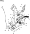
FIG. 2 is a perspective view illustrating, extracted, main components of the motorcycle. -
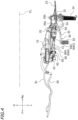
FIG. 3 is a left side view illustrating, extracted, main components of the motorcycle. -
FIG. 4 is a plan view illustrating, extracted, main components of the motorcycle. -
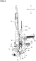
FIG. 5 is a front view illustrating, extracted, main components of the motorcycle. -
FIG. 6 is a left side view of a sensor rod and a wire harness. - An embodiment will now be described with reference to the drawings.
FIG. 1 is a left side view of amotorcycle 1, which is an example of a straddled vehicle. - The terms front, rear, left, right, up and down, as used in the description below, refer to these directions as seen from a virtual rider seated on a
seat 2 while themotorcycle 1 is standing upright on a horizontal surface with no rider and no load thereon, unless specified otherwise. The designations F, Re, L, R, U and D, as used in the figures, refer to front, rear, left, right, up and down, respectively. The term "front/forward" refers not only to the direction that extends in the front direction along the vehicle center line CL (seeFIG. 4 ), as the vehicle is seen from above, but also to directions that are inclined left/right from that direction by an angle that is less than or equal to 45 degrees. Similarly, the term "rear/rearward" refers not only to the direction that extends rearward along the vehicle center line CL, as the vehicle is seen from above, but also to directions that are inclined left/right from that direction by an angle of 45 degrees of less. The term "left/leftward" refers not only to the direction that extends leftward vertical to the vehicle center line CL, as the vehicle is seen from above, but also to directions that are inclined frontward/rearward from that direction by an angle of 45 degrees of less. The term "right/rightward" refers not only to the direction that extends rightward vertical to the vehicle center line CL, as the vehicle is seen from above, but also to directions that are inclined frontward/rearward from that direction by an angle of 45 degrees of less. The term "up/upward" refers not only to the vertically upward direction, as the vehicle is seen from the side, but also to directions that are inclined frontward/rearward from that direction by an angle of 45 degrees of less. The term "down/downward" refers not only to the vertically downward direction, as the vehicle is seen from the side, but also to directions that are inclined frontward/rearward from that direction by an angle of 45 degrees of less. The vehicle left and right direction (L↔R), the vehicle up and down direction (U↔D) and the vehicle front and rear direction (F↔Re) refer to the main directions of the vehicle as indicated in the figures. - As shown in
FIG. 1 , themotorcycle 1 includes avehicle body frame 3, theseat 2 supported on thevehicle body frame 3, afront wheel 4, arear wheel 5, ahandle bar 6 for steering thefront wheel 4, and an internal combustion engine (hereinafter referred to as an engine) 7 for driving therear wheel 5. Theengine 7 is supported on thevehicle body frame 3. - The
vehicle body frame 3 includes a left andright side frame 10 extending downward. The side frames 10 are arranged sideward of theengine 7. As shown inFIG. 1 , theleft side frame 10 is arranged leftward of theengine 7. - A
pivot shaft 11 is supported on theside frame 10. A front end portion of arear arm 8 is pivotally linked to thepivot shaft 11. Therear arm 8 is pivotally linked to theside frame 10 with thepivot shaft 11 therebetween. Therear wheel 5 is rotatably linked to a rear end portion of therear arm 8. Theengine 7 and therear wheel 5 are linked together by achain 9, which is an example of a power transmission member. - Although not shown in the figures, the
engine 7 includes a stepped transmission. Ashift shaft 16 of the transmission is provided on theengine 7. As theshift shaft 16 rotates, the gear of the transmission is changed. A portion of theshift shaft 16 is arranged outside theengine 7. - The
motorcycle 1 includes afootrest bracket 20, ashift pedal 30 for operating theshift shaft 16, ashift rod 40 that links together theshift shaft 16 and theshift pedal 30, awire harness 60, aside stand 70, and aside stand switch 80.FIG. 2 ,FIG. 3 ,FIG. 4 andFIG. 5 respectively show a perspective view, a left side view, a plan view and a front view of these components (hereinafter referred to as main components). - As shown in
FIG. 2 , thefootrest bracket 20 is secured to theside frame 10 bybolts 24. Thefootrest bracket 20 is arranged rearward of theside frame 10. Thefootrest bracket 20 includes anupper arm 21, alower arm 22 arranged downward of theupper arm 21, and aside cover 23. As shown inFIG. 3 , theside cover 23 extends upward and rearward from theupper arm 21. As shown inFIG. 2 , a front portion of theupper arm 21 and a front portion of thelower arm 22 are secured to theside frame 10 by thebolts 24. A rear portion of theupper arm 21 and a rear portion of thelower arm 22 are formed integral together. The side cover 23 is formed integral with theupper arm 21. - The
shift pedal 30 is operated by a foot of the rider. Theshift pedal 30 is attached to thefootrest bracket 20. Theshift pedal 30 includes apedal support shaft 31 that is rotatable up and down, apedal arm 32 that extends forward from thepedal support shaft 31, apedal operation shaft 33 that extends leftward from thepedal arm 32, and alink arm 35 that extend downward from thepedal support shaft 31. Thepedal operation shaft 33 extends outward in the vehicle width direction from thepedal arm 32. Note that "outward in the vehicle width direction" refers to the direction away from the vehicle center line CL (seeFIG. 4 ). "Inward in the vehicle width direction" refers to the direction toward the vehicle center line. As shown inFIG. 3 , thepedal operation shaft 33 overlaps with theside frame 10 as the vehicle is seen from the side. Thepedal support shaft 31 is rotatably supported on thefootrest bracket 20. As shown inFIG. 4 , afootrest 34 is arranged outward in the vehicle width direction of thepedal support shaft 31. Thefootrest 34 is arranged leftward of thepedal support shaft 31 and extends leftward. - A foot of the rider rests on the
footrest 34. Thepedal operation shaft 33 is moved upward or downward by the toe of the foot of the rider. Theshift pedal 30 is operated so that thepedal operation shaft 33 moves upward when shifting up, and is operated so that thepedal operation shaft 33 moves downward when shifting the gear down. InFIG. 3 , theshift pedal 30 rotates clockwise about a center of thepedal support shaft 31 when shifting up, and rotates counterclockwise about the center of thepedal support shaft 31 when shifting down. - The
shift rod 40 includes amain rod 41 and awaterproof sensor 50. A front end portion of themain rod 41 is linked to theshift shaft 16 with alink arm 42 therebetween. Theshift shaft 16 is rotatably connected to an upper end portion of thelink arm 42. The front end portion of themain rod 41 is rotatably connected to a lower end portion of thelink arm 42. A rear end portion of themain rod 41 is connected to a front end portion of thewaterproof sensor 50. A rear end portion of thewaterproof sensor 50 is rotatably connected to thelink arm 35 of theshift pedal 30. - The
waterproof sensor 50 is a waterproof sensor that detects contraction of theshift rod 40. As shown inFIG. 6 , thewaterproof sensor 50 includes a rod-shapedsensor rod 51, acasing 52 that axially slidably supports thesensor rod 51, amechanical switch 53 that is turned ON/OFF by contact with thesensor rod 51, aswitch case 54 that houses theswitch 53 therein, and a spring (not shown) that urges thesensor rod 51 away from theswitch 53. Thecasing 52 and theswitch case 54 have a watertight structure (not shown) that prevents water from entering. Afront end portion 51 a of thesensor rod 51 is connected to arear end portion 41 b of themain rod 41. - As described above, in
FIG. 3 , theshift pedal 30 rotates clockwise when shifting up. A compressive force is applied to theshift rod 40 when shifting up. When a compressive force is applied to theshift rod 40, thesensor rod 51 moves toward theswitch 53 and comes into contact with theswitch 53. Thus, theswitch 53 is turned ON. Thewaterproof sensor 50 is configured to detect a shift-up operation of theshift pedal 30. Upon completion of the shift-up operation by the rider P, thesensor rod 51 receives the force of the spring to return to the neutral position away from theswitch 53. - Note that in the present embodiment, the
waterproof sensor 50 is configured not to detect extension of theshift rod 40. Thewaterproof sensor 50 is configured not to detect a shift-down operation of theshift pedal 30. - As shown in
FIG. 3 , at least a portion of thewaterproof sensor 50 is arranged rearward relative to theside frame 10. Note that "arranged rearward relative to theside frame 10" means being arranged rearward relative to the rear edge of theside frame 10 as the vehicle is seen from the side. Thewaterproof sensor 50 is arranged rearward relative to thepedal operation shaft 33. Thewaterproof sensor 50 is arranged rearward relative to thepivot shaft 11. Theswitch case 54 is arranged rearward relative to theside frame 10. As shown inFIG. 4 andFIG. 5 , thewaterproof sensor 50 is arranged leftward relative to theside frame 10 and rightward relative to theshift pedal 30. Thewaterproof sensor 50 is arranged outward in the vehicle width direction relative to theside frame 10 and inward in the vehicle width direction relative to theshift pedal 30. - As shown in
FIG. 3 , thefootrest bracket 20 is arranged upward of thewaterproof sensor 50. As shown inFIG. 5 , theside cover 23 of thefootrest bracket 20 includes aninclined portion 23a that extends upward and outward in the vehicle width direction, and avertical portion 23b that extends upward from theinclined portion 23a. As shown inFIG. 4 , thefootrest bracket 20 overlaps with at least a portion of thewaterproof sensor 50 as the vehicle is seen from above. - The
wire harness 60 is connected to thewaterproof sensor 50. As shown inFIG. 6 , theswitch case 54 is formed with aconnection port 54a that is open forward. Thewire harness 60 is connected to theconnection port 54a. Inside theswitch case 54, a first end portion of thewire harness 60 is connected to theswitch 53. Thewire harness 60 extends forward from theswitch case 54. Thewire harness 60 does not protrude downward from theswitch case 54. A second end portion of thewire harness 60 is connected to an ECU (Electronic Control Unit) 90 (seeFIG. 3 ). - The
ECU 90 is configured to receive a signal from thewaterproof sensor 50 to perform a control of temporarily lowering the output power of theengine 7. When thewaterproof sensor 50 detects a shift-up operation, theECU 90 temporarily lowers the output power of theengine 7, thereby reducing the torque for driving the gear (not shown) of the transmission. Thus, it is possible to perform a shift change without releasing the accelerator, for example. It is also possible to perform a shift change without disconnecting the clutch. Therefore, it is possible to quickly perform a shift change. It is also possible to reduce the burden of the shift operation of the rider. - A portion of the
wire harness 60 is covered by aharness cover 66. Theharness cover 66 is formed in a hose shape. A portion of thewire harness 60 is inserted in theharness cover 66. - As shown in
FIG. 6 , theharness cover 66 includes anoverlap portion 66A that overlaps with theside frame 10 as the vehicle is seen from the side, afront portion 66B that is located forward of theoverlap portion 66A, and arear portion 66C that is located rearward of theoverlap portion 66A. Herein, theoverlap portion 66A and therear portion 66C are arranged directly under theshift rod 40. As shown inFIG. 4 , theoverlap portion 66A and therear portion 66C of theharness cover 66 overlap with theshift rod 40 as the vehicle is seen from above. - As described above, the
wire harness 60 is inserted in theharness cover 66. As shown inFIG. 6 , thewire harness 60 includes anoverlap portion 60A that overlaps with theside frame 10 as the vehicle is seen from the side, afront portion 60B that is located forward of theoverlap portion 60A, and arear portion 60C that is located rearward of theoverlap portion 60A. Theoverlap portion 60A and therear portion 60C of thewire harness 60 are arranged downward of theshift rod 40. Herein, theoverlap portion 60A and therear portion 60C are arranged directly under theshift rod 40. As the vehicle is seen from above, theoverlap portion 60A and therear portion 60C of thewire harness 60 overlap with the shift rod 40 (seeFIG. 4 ). - As shown in
FIG. 6 , thewire harness 60, together with theharness cover 66, is tied to theshift rod 40 by acable tie 65. Theoverlap portion 60A and therear portion 60C of thewire harness 60 are arranged along theshift rod 40, together with theoverlap portion 66A and therear portion 66C of theharness cover 66. Herein, thewire harness 60 and theharness cover 66 are tied to themain rod 41 by thecable tie 65. Note however that thewire harness 60 and theharness cover 66 may be tied to thewaterproof sensor 50 by thecable tie 65. There is no limitation on the number of cable ties 65. Thewire harness 60 and theharness cover 66 may be tied only to one of themain rod 41 and thewaterproof sensor 50 or may be tied to both of them. While thecable tie 65 is an example of a fastening member for fastening thewire harness 60 to theshift rod 40, there is no particular limitation on the fastening member. The fastening member is not limited to a band-shaped member, but it may be a chord-shaped member or may be any other member. - As shown in
FIG. 3 , thewaterproof sensor 50 is arranged in the vicinity of theshift pedal 30. Themotorcycle 1 includes aguard member 36 that prevents the foot of the rider who operates theshift pedal 30 from hitting thewaterproof sensor 50. Theguard member 36 overlaps with thewaterproof sensor 50 as the vehicle is seen from the side. As the vehicle is seen from the side, at least a portion of theguard member 36 overlaps with theswitch case 54. Herein, theguard member 36 is secured to theshift pedal 30. Theguard member 36 is a rod-shaped member. Note however that there is no particular limitation on the shape of theguard member 36. Theguard member 36 may be a plate-shaped member, for example. - As described above, the
overlap portion 66A and therear portion 66C of theharness cover 66 are arranged downward of theshift rod 40, together with theoverlap portion 60A and therear portion 60C of thewire harness 60. Theguard member 36 prevents the foot of the rider from hitting theharness cover 66 and thewire harness 60. - A
bracket 76 is secured to a lower portion of theside frame 10. The side stand 70 is rotatably supported on thebracket 76. The side stand 70 includes aproximal portion 71 that is supported on thebracket 76 so as to be rotatable up and down, and adistal portion 72. The side stand 70 is configured to be rotatable between the standing position in which thedistal portion 72 is located downward of theproximal portion 71 and the retracted position in which thedistal portion 72 is located rearward of theproximal portion 71. Note thatFIG. 3 shows a state where the side stand 70 is in the retracted position. When themotorcycle 1 is parked, the side stand 70 is positioned in the standing position. When the side stand 70 is in the standing position, thedistal portion 72 is in contact with the ground. When the rider rides on themotorcycle 1, the side stand 70 is positioned in the retracted position. When the side stand 70 is in the retracted position, thedistal portion 72 is located upward relative to the ground, and spaced apart from the ground. As shown inFIG. 3 , when themotorcycle 1 is standing upright on a horizontal surface and the side stand 70 is in the retracted position, thewaterproof sensor 50 is arranged upward relative to theside stand 70, rearward relative to theproximal portion 71 of the side stand 70 and forward relative to thedistal portion 72 of theside stand 70. - The side stand
switch 80 is attached to theproximal portion 71 of theside stand 70. The side standswitch 80 is configured to detect the position of theside stand 70. The side standswitch 80 is turned ON or OFF when the position of the side stand 70 is switched from the standing position to the retracted position or switched from the retracted position to the standing position. Awire harness 81 is connected to the side standswitch 80. Thewire harness 81 extends forward. A front end portion of thewire harness 81 is connected to theECU 90. Thewaterproof sensor 50 is arranged rearward and upward of the side standswitch 80. - The
motorcycle 1 of the present embodiment is configured as described above. Next, various advantageous effects of themotorcycle 1 will be described. - The
motorcycle 1 of the present embodiment includes thewaterproof sensor 50 as a sensor for detecting the operation of theshift pedal 30. Therefore, it is possible to run with no problems on bad terrains with many puddles, etc. However, thewaterproof sensor 50 is larger in size as compared with a sensor that is not waterproof. - According to the present embodiment, the
waterproof sensor 50 is arranged relatively rearward. At least a portion of thewaterproof sensor 50 is arranged rearward relative to theside frame 10. The space rearward of theside frame 10 is used as a space for installment for at least a portion of thewaterproof sensor 50. Thewaterproof sensor 50 and theside frame 10 are unlikely to interfere with each other. Therefore, despite the provision of thewaterproof sensor 50, it is possible to suppress an increase in size around thewaterproof sensor 50 in the vehicle width direction. - When the
waterproof sensor 50 is arranged relatively rearward, there may occur interference between theoverlap portion 60A and therear portion 60C of thewire harness 60 and theside frame 10 and interference between theoverlap portion 60A and therear portion 60C of thewire harness 60 and theshift rod 40. However, according to the present embodiment, theoverlap portion 60A and therear portion 60C of thewire harness 60 is arranged downward of theshift rod 40. Thus, it is possible to avoid such interference while suppressing an increase in size in the vehicle width direction. - Therefore, according to the present embodiment, the
waterproof sensor 50 can be used as a sensor provided on theshift rod 40 while suppressing an increase in size in the vehicle width direction. - According to the present embodiment, the
waterproof sensor 50 is arranged rearward relative to thepedal operation shaft 33. The space rearward relative to thepedal operation shaft 33 is used as a space for installment of thewaterproof sensor 50. Since thewaterproof sensor 50 is arranged more rearward, it is possible to further suppress an increase in size in the vehicle width direction. - According to the present embodiment, as shown in
FIG. 6 , thewaterproof sensor 50 includes thesensor rod 51 and themechanical switch 53 that is turned ON/OFF through contact with thesensor rod 51. Thewaterproof sensor 50 is a mechanical sensor. Thewaterproof sensor 50 can be made inexpensive as compared with an optical sensor. - The
waterproof sensor 50 includes theswitch case 54 housing theswitch 53. Theswitch case 54 has a watertight structure. The vertical size of theswitch case 54 is greater than the vertical size of the other portion of thewaterproof sensor 50. Theswitch case 54 is larger than the other portion of thewaterproof sensor 50. According to the present embodiment, theswitch case 54 is arranged rearward relative to theside frame 10. Therefore, theswitch case 54 and theside frame 10 do not interfere with each other, and it is possible to suppress an increase in size in the vehicle width direction. - The
switch case 54 includes theconnection port 54a that is open forward, and thewire harness 60 is connected to theconnection port 54a. Thewire harness 60 extends forward from theswitch case 54. A situation where thewire harness 60 protrudes downward from theswitch case 54 is avoided. Therefore, it is possible to arrange thewire harness 60 in a compact arrangement. - According to the present embodiment, as shown in
FIG. 4 , theoverlap portion 60A and therear portion 60C of thewire harness 60 overlap with theshift rod 40 as the vehicle is seen from above. Theoverlap portion 60A and therear portion 60C of thewire harness 60 do not protrude outward in the vehicle width direction. Therefore, it is possible to suppress an increase in size in the vehicle width direction. - According to the present embodiment, as shown in
FIG. 6 , thewire harness 60, together with theharness cover 66, is secured to theshift rod 40 by thecable tie 65. Thewire harness 60, together with theharness cover 66, can be made to conform to theshift rod 40. Therefore, thewire harness 60 and theharness cover 66 can be arranged in a compact arrangement. - According to the present embodiment, the
wire harness 60 is covered by theharness cover 66. It is possible to protect thewire harness 60 from gravel, mud, etc., kicked up from the road surface. When the rider operates theshift pedal 30 or theside stand 70, it is possible to protect thewire harness 60 from the foot of the rider. Although theharness cover 66 has a larger diameter than thewire harness 60, theoverlap portion 66A and therear portion 66C of theharness cover 66 are arranged downward of theshift rod 40 and overlap with theshift rod 40 as the vehicle is seen from above (seeFIG. 4 ). Theoverlap portion 66A and therear portion 66C of theharness cover 66 do not protrude outward in the vehicle width direction relative to theshift rod 40. Therefore, it is possible to suppress an increase in size in the vehicle width direction. - According to the present embodiment, as shown in
FIG. 5 , thewaterproof sensor 50 is arranged outward in the vehicle width direction relative to theside frame 10 and inward in the vehicle width direction relative to theshift pedal 30. Thewaterproof sensor 50 is arranged in a compact arrangement between theside frame 10 and theshift pedal 30. - According to the present embodiment, as shown in
FIG. 3 , thewaterproof sensor 50 is arranged relatively rearward, and the foot of the rider may possibly hit thewaterproof sensor 50 when operating theshift pedal 30. However, theshift pedal 30 is provided with theguard member 36. Theguard member 36 prevents the foot of the rider from hitting thewaterproof sensor 50. - According to the present embodiment, when the
motorcycle 1 is standing upright on a horizontal surface and the side stand 70 is in the retracted position, thewaterproof sensor 50 is arranged upward relative to theside stand 70, rearward relative to theproximal portion 71 of the side stand 70 and forward relative to thedistal portion 72 of theside stand 70. Thewaterproof sensor 50 and the side stand 70 can be arranged in a compact arrangement while avoiding interference therebetween. - The
waterproof sensor 50 is arranged rearward and upward of the side standswitch 80. Thewaterproof sensor 50 and the side standswitch 80 can be arranged in a compact arrangement while avoiding interference therebetween. - According to the present embodiment, the
footrest bracket 20 is arranged upward relative to thewaterproof sensor 50 as shown inFIG. 3 , and overlaps with at least a portion of thewaterproof sensor 50 as the vehicle is seen from above as shown inFIG. 4 . Thewaterproof sensor 50 is arranged directly under at least a portion of the footrest bracket 20 (seeFIG. 5 ). Therefore, it is possible to suppress an increase in size in the vehicle width direction. - Although the
waterproof sensor 50 may be configured to detect both contraction and extension of theshift rod 40, it is configured to detect only contraction of theshift rod 40 in the present embodiment. Therefore, thewaterproof sensor 50 can be made smaller as compared with a case where thewaterproof sensor 50 is configured to detect both contraction and extension of theshift rod 40. - One embodiment has been described above. However, the embodiment described above is merely an example, and various other embodiments are possible without departing from the scope of the present invention disclosed by the appended claims. Next, examples of other embodiments will be described briefly.
- The position in the front-rear direction of the
waterproof sensor 50 may be changed as needed. While only a portion of thewaterproof sensor 50 may be arranged rearward relative to theside frame 10, the entirety of thewaterproof sensor 50 may be arranged rearward relative to theside frame 10. - The
shift rod 40 may be configured to extend when shifting up. For example, the connecting portion between theshift rod 40 and theshift pedal 30 may be located upward of thepedal support shaft 31. In such a case, thewaterproof sensor 50 may be configured to detect only extension of theshift rod 40. - A portion of the
waterproof sensor 50 may be arranged forward relative to thepedal operation shaft 33. Thepedal operation shaft 33 may be arranged forward relative to theside frame 10. - The
waterproof sensor 50 may be an optical sensor. At least a portion of theswitch case 54 of thewaterproof sensor 50 may overlap with theside frame 10 as the vehicle is seen from the side. - The
connection port 54a of theswitch case 54 may be open downward. Thewire harness 60 may extend downward from theswitch case 54 and then extend forward. - The
overlap portion 60A and/or therear portion 60C of thewire harness 60 do not need to be arranged directly under theshift rod 40. Theoverlap portion 60A and/or therear portion 60C of thewire harness 60 do not need to overlap with theshift rod 40 as the vehicle is seen from above. - The
wire harness 60 does not need to be secured on theshift rod 40. For example, thewire harness 60 may be secured to another vehicle part. - The
harness cover 66 may be absent. Theoverlap portion 66A and/or therear portion 66C of theharness cover 66 do not need to be arranged directly under theshift rod 40. Theoverlap portion 66A and/or therear portion 66C of theharness cover 66 do not need to overlap with theshift rod 40 as the vehicle is seen from above. - The
guard member 36 may be provided on a vehicle part other than theshift pedal 30. Theguard member 36 may be absent. - The side stand
switch 80 may be absent. - The
footrest bracket 20 does not need to overlap with thewaterproof sensor 50 as the vehicle is seen from above. Theshift pedal 30 does not need to be supported on thefootrest bracket 20. Theshift pedal 30 may be supported on a vehicle part other than thefootrest bracket 20. Thefootrest bracket 20 may be absent. - A straddled vehicle refers to a vehicle that is straddled by a rider. The straddled vehicle is not limited to the
motorcycle 1. The straddled vehicle may be an auto tricycle, an ATV (All Terrain Vehicle), or a snowmobile, for example. - 1: Motorcycle (straddled vehicle), 7: Internal combustion engine, 8: Rear arm, 10: Side frame, 11: Pivot shaft, 16: Shift shaft, 20: Footrest bracket, 30: Shift pedal, 31: Pedal support shaft, 32: Pedal arm, 33: Pedal operation shaft, 36: Guard member, 40: Shift rod, 50: Waterproof sensor, 51: Sensor rod, 53: Mechanical switch, 54: Switch case, 54a: Connection port, 60: Wire harness, 60A: Overlap portion, 60C: Rear portion, 65: Cable tie (fastening member), 66: Harness cover, 66A: Overlap portion, 66C: Rear portion, 70: Side stand, 71: Proximal portion, 72: Distal portion, 80: Side stand switch, 90: ECU (controller)
Claims (15)
- A straddled vehicle (1) comprising:an internal combustion engine (7);a side frame (10) that is arranged sideward of the internal combustion engine (7) with regard to a vehicle left and right direction and extending downward with regard to a vehicle up and down direction;a shift shaft (16) provided on the internal combustion engine (7);a shift pedal (30);a shift rod (40) that links together the shift shaft (16) and the shift pedal (30), wherein a portion of the shift rod (40) overlaps with the side frame (10) as the vehicle is seen from the side;a sensor (50) that is provided on the shift rod (40) and is configured to detect contraction or extension of the shift rod (40), at least a portion of the sensor (50) is arranged rearward relative to the side frame (10) with regard to a vehicle front and rear direction; anda wire harness (60) connected to the sensor (50), the wire harness (60) includes an overlap portion (60A) that overlaps with the side frame (10) as the vehicle is seen from the side and is arranged downward of the shift rod (40) with regard to the vehicle up and down direction, characterized in thatthe sensor is a waterproof sensor (50), andthe wire harness (60) includes a rear portion (60C) that is located rearward of the overlap portion (60A) with regard to the vehicle front and rear direction;the rear portion (60C) of the wire harness (60) is arranged downward of the shift rod (40) with regard to the vehicle up and down direction.
- The straddled vehicle (1) according to claim 1, characterized in that the shift pedal (30) includes a pedal support shaft (31) that is rotatable up and down with regard to the vehicle up and down direction, a pedal arm (32) that extends forward from the pedal support shaft (31) with regard to the vehicle front and rear direction, and a pedal operation shaft (33) that extends outward in a vehicle width direction and the vehicle left and right direction from the pedal arm (32); and
the waterproof sensor (50) is arranged rearward relative to the pedal operation shaft (33) with regard to the vehicle front and rear direction. - The straddled vehicle (1) according to claim 2, characterized in that the pedal operation shaft (33) overlaps with the side frame (10) as the vehicle is seen from the side.
- The straddled vehicle according to any one of claims 1 to 3, characterized in that the waterproof sensor (50) includes a sensor rod (51), and a mechanical switch (53) that is configured to be turned ON/OFF through contact with the sensor rod (51).
- The straddled vehicle (1) according to claim 4, characterized in that the waterproof sensor (50) includes a switch case (54) housing the mechanical switch (53); and whereinthe switch case (54) is arranged rearward relative to the side frame (10) with regard to the vehicle front and rear direction, and/orthe switch case (54) includes a connection port (54a) that is open forward with regard to the vehicle front and rear direction and the wire harness (60) is connected to the connection port (54a).
- The straddled vehicle according to any one of claims 1 to 5, characterized in that the overlap portion (60A) and the rear portion (60C) of the wire harness (60) overlap with the shift rod (40) as the vehicle is seen from above.
- The straddled vehicle according to any one of claims 1 to 6, comprising a fastening member (65) that fastens the wire harness (60) to the shift rod (40).
- The straddled vehicle according to any one of claims 1 to 7, characterized by a hose-shaped harness cover (66) in which the wire harness (60) is inserted,
wherein the harness cover (66) includes a portion (66A, 66C) that is arranged downward of the shift rod (40) with regard to the vehicle up and down direction and overlaps with the shift rod (40) as the vehicle is seen from above. - The straddled vehicle according to any one of claims 1 to 8, characterized in that the waterproof sensor (50) is arranged outward in a vehicle width direction and the vehicle left and right direction relative to the side frame (10) and inward in the vehicle width direction and the vehicle left and right direction relative to the shift pedal (30), and/or
the straddled vehicle comprises a guard member (36) that is arranged outward of the waterproof sensor (50) in a vehicle width direction and the vehicle left and right direction, overlaps with the waterproof sensor (50) as the vehicle is seen from the side, and prevents a foot of a rider operating the shift pedal (30) from hitting the waterproof sensor (50). - The straddled vehicle according to any one of claims 1 to 9, characterized by a side stand (70) including a proximal portion (71) that is supported so as to be rotatable up and down with regard to the vehicle up and down direction, and a distal portion (72), wherein:the side stand (70) is configured to be rotatable between a standing position in which the distal portion (72) is located downward of the proximal portion (71) with regard to the vehicle up and down direction and a retracted position in which the distal portion (72) is located rearward of the proximal portion (71) with regard to the vehicle front and rear direction; andwhen the straddled vehicle (1) is standing upright on a horizontal surface and the side stand (70) is in the retracted position, the waterproof sensor (50) is arranged upward relative to the side stand (70) with regard to the vehicle up and down direction, rearward relative to the proximal portion (71) of the side stand (70) and forward relative to the distal portion (72) of the side stand (70) with regard to the vehicle front and rear direction.
- The straddled vehicle (1) according to claim 10, characterized by a side stand switch (80) that is attached to the proximal portion (71) of the side stand (70) and is configured to detect a position of the side stand (70),
wherein the waterproof sensor (50) is arranged rearward with regard to the vehicle front and rear direction and upward with regard to the vehicle up and down direction of the side stand switch (80). - The straddled vehicle according to any one of claims 1 to 11, characterized by a footrest bracket (20) that is secured on the side frame (10) and arranged rearward of the side frame (10) with regard to the vehicle front and rear direction, wherein:the shift pedal (30) is attached to the footrest bracket (20); andthe footrest bracket (20) is arranged upward relative to the waterproof sensor (50) with regard to the vehicle up and down direction and overlaps with at least a portion of the waterproof sensor (50) as the vehicle is seen from above.
- The straddled vehicle according to any one of claims 1 to 12, characterized by a controller (90) connected to the wire harness (60),
wherein the controller (90) is configured to receive a signal from the waterproof sensor (50) to perform a control of temporarily lowering an output power of the internal combustion engine (7). - The straddled vehicle according to any one of claims 1 to 13, characterized by:a pivot shaft (11) supported on the side frame (10); anda rear arm (8) pivotally linked to the side frame (10) with the pivot shaft (11) therebetween,wherein the waterproof sensor (50) is arranged rearward relative to the pivot shaft (11).
- The straddled vehicle (1) according to any one of claims 1 to 14, characterized in that the waterproof sensor (50) is configured to detect only one of contraction and extension of the shift rod (40).
Applications Claiming Priority (1)
| Application Number | Priority Date | Filing Date | Title |
|---|---|---|---|
| JP2020182691A JP2022072967A (en) | 2020-10-30 | 2020-10-30 | Saddle type vehicle |
Publications (2)
| Publication Number | Publication Date |
|---|---|
| EP3992072A1 EP3992072A1 (en) | 2022-05-04 |
| EP3992072B1 true EP3992072B1 (en) | 2023-07-19 |
Family
ID=77206966
Family Applications (1)
| Application Number | Title | Priority Date | Filing Date |
|---|---|---|---|
| EP21189355.7A Active EP3992072B1 (en) | 2020-10-30 | 2021-08-03 | Straddled vehicle shift pedal sensor |
Country Status (3)
| Country | Link |
|---|---|
| EP (1) | EP3992072B1 (en) |
| JP (1) | JP2022072967A (en) |
| BR (1) | BR102021019670A2 (en) |
Families Citing this family (3)
| Publication number | Priority date | Publication date | Assignee | Title |
|---|---|---|---|---|
| IT202200012170A1 (en) | 2022-06-08 | 2023-12-08 | Ferrari Spa | MOTOR VEHICLE |
| JP2024086040A (en) | 2022-12-16 | 2024-06-27 | ヤマハ発動機株式会社 | Vehicle wire harness and straddle-type vehicle equipped with same |
| JP7798946B2 (en) * | 2024-03-22 | 2026-01-14 | 本田技研工業株式会社 | Sensor arrangement structure of pedal device |
Family Cites Families (3)
| Publication number | Priority date | Publication date | Assignee | Title |
|---|---|---|---|---|
| JP2987532B2 (en) | 1991-07-22 | 1999-12-06 | ヤマハ発動機株式会社 | Transmission control device for motorcycle |
| JP2019023018A (en) * | 2017-07-24 | 2019-02-14 | 川崎重工業株式会社 | Vehicle speed change mechanism |
| JP7032974B2 (en) * | 2018-03-30 | 2022-03-09 | カワサキモータース株式会社 | Vehicle with derailleur |
-
2020
- 2020-10-30 JP JP2020182691A patent/JP2022072967A/en active Pending
-
2021
- 2021-08-03 EP EP21189355.7A patent/EP3992072B1/en active Active
- 2021-09-30 BR BR102021019670-0A patent/BR102021019670A2/en unknown
Also Published As
| Publication number | Publication date |
|---|---|
| JP2022072967A (en) | 2022-05-17 |
| EP3992072A1 (en) | 2022-05-04 |
| BR102021019670A2 (en) | 2022-05-17 |
Similar Documents
| Publication | Publication Date | Title |
|---|---|---|
| EP3992072B1 (en) | Straddled vehicle shift pedal sensor | |
| US7174984B2 (en) | Motorcycle | |
| EP4053433B1 (en) | Shift device | |
| EP2221206B1 (en) | Scooter type vehicle | |
| EP1854710B1 (en) | Stand of motorcycle | |
| US7845449B2 (en) | Handlebar lock for a vehicle | |
| JP7798946B2 (en) | Sensor arrangement structure of pedal device | |
| EP4470893A1 (en) | Straddled vehicle | |
| JP7573583B2 (en) | ABS modulator piping arrangement structure | |
| JP2019023018A (en) | Vehicle speed change mechanism | |
| JP5775914B2 (en) | Cable routing structure for electrical components in saddle-ride type vehicles | |
| JP2012180762A (en) | Throttle control device | |
| JP4828995B2 (en) | Saddle type vehicle and clutch actuator assembly method for saddle type vehicle | |
| JP4495642B2 (en) | Passenger rice transplanter | |
| US11072393B2 (en) | Transmission for saddled vehicle | |
| JP7210624B2 (en) | straddle-type vehicle | |
| JP4566829B2 (en) | Passenger rice transplanter | |
| JP7793591B2 (en) | Saddle-type vehicle | |
| JP7590589B2 (en) | Saddle-type vehicle | |
| EP3960604B1 (en) | Scooter type vehicle | |
| JP7606497B2 (en) | Handle lock pin protection structure | |
| WO2022157807A1 (en) | A gearshift mechanism for a saddle-type motor vehicle | |
| WO2025074647A1 (en) | Leaning vehicle | |
| WO2025074649A1 (en) | Leaning vehicle | |
| JP2026062329A (en) | Clutch control device and saddle-type vehicle |
Legal Events
| Date | Code | Title | Description |
|---|---|---|---|
| PUAI | Public reference made under article 153(3) epc to a published international application that has entered the european phase |
Free format text: ORIGINAL CODE: 0009012 |
|
| STAA | Information on the status of an ep patent application or granted ep patent |
Free format text: STATUS: THE APPLICATION HAS BEEN PUBLISHED |
|
| AK | Designated contracting states |
Kind code of ref document: A1 Designated state(s): AL AT BE BG CH CY CZ DE DK EE ES FI FR GB GR HR HU IE IS IT LI LT LU LV MC MK MT NL NO PL PT RO RS SE SI SK SM TR |
|
| STAA | Information on the status of an ep patent application or granted ep patent |
Free format text: STATUS: REQUEST FOR EXAMINATION WAS MADE |
|
| 17P | Request for examination filed |
Effective date: 20221025 |
|
| RBV | Designated contracting states (corrected) |
Designated state(s): AL AT BE BG CH CY CZ DE DK EE ES FI FR GB GR HR HU IE IS IT LI LT LU LV MC MK MT NL NO PL PT RO RS SE SI SK SM TR |
|
| GRAP | Despatch of communication of intention to grant a patent |
Free format text: ORIGINAL CODE: EPIDOSNIGR1 |
|
| STAA | Information on the status of an ep patent application or granted ep patent |
Free format text: STATUS: GRANT OF PATENT IS INTENDED |
|
| INTG | Intention to grant announced |
Effective date: 20230310 |
|
| GRAS | Grant fee paid |
Free format text: ORIGINAL CODE: EPIDOSNIGR3 |
|
| GRAA | (expected) grant |
Free format text: ORIGINAL CODE: 0009210 |
|
| STAA | Information on the status of an ep patent application or granted ep patent |
Free format text: STATUS: THE PATENT HAS BEEN GRANTED |
|
| P01 | Opt-out of the competence of the unified patent court (upc) registered |
Effective date: 20230527 |
|
| AK | Designated contracting states |
Kind code of ref document: B1 Designated state(s): AL AT BE BG CH CY CZ DE DK EE ES FI FR GB GR HR HU IE IS IT LI LT LU LV MC MK MT NL NO PL PT RO RS SE SI SK SM TR |
|
| REG | Reference to a national code |
Ref country code: GB Ref legal event code: FG4D |
|
| REG | Reference to a national code |
Ref country code: CH Ref legal event code: EP |
|
| REG | Reference to a national code |
Ref country code: DE Ref legal event code: R096 Ref document number: 602021003561 Country of ref document: DE |
|
| REG | Reference to a national code |
Ref country code: IE Ref legal event code: FG4D |
|
| REG | Reference to a national code |
Ref country code: LT Ref legal event code: MG9D |
|
| REG | Reference to a national code |
Ref country code: NL Ref legal event code: MP Effective date: 20230719 |
|
| REG | Reference to a national code |
Ref country code: AT Ref legal event code: MK05 Ref document number: 1589217 Country of ref document: AT Kind code of ref document: T Effective date: 20230719 |
|
| PG25 | Lapsed in a contracting state [announced via postgrant information from national office to epo] |
Ref country code: NL Free format text: LAPSE BECAUSE OF FAILURE TO SUBMIT A TRANSLATION OF THE DESCRIPTION OR TO PAY THE FEE WITHIN THE PRESCRIBED TIME-LIMIT Effective date: 20230719 |
|
| PG25 | Lapsed in a contracting state [announced via postgrant information from national office to epo] |
Ref country code: GR Free format text: LAPSE BECAUSE OF FAILURE TO SUBMIT A TRANSLATION OF THE DESCRIPTION OR TO PAY THE FEE WITHIN THE PRESCRIBED TIME-LIMIT Effective date: 20231020 |
|
| PG25 | Lapsed in a contracting state [announced via postgrant information from national office to epo] |
Ref country code: IS Free format text: LAPSE BECAUSE OF FAILURE TO SUBMIT A TRANSLATION OF THE DESCRIPTION OR TO PAY THE FEE WITHIN THE PRESCRIBED TIME-LIMIT Effective date: 20231119 |
|
| PG25 | Lapsed in a contracting state [announced via postgrant information from national office to epo] |
Ref country code: SE Free format text: LAPSE BECAUSE OF FAILURE TO SUBMIT A TRANSLATION OF THE DESCRIPTION OR TO PAY THE FEE WITHIN THE PRESCRIBED TIME-LIMIT Effective date: 20230719 Ref country code: RS Free format text: LAPSE BECAUSE OF FAILURE TO SUBMIT A TRANSLATION OF THE DESCRIPTION OR TO PAY THE FEE WITHIN THE PRESCRIBED TIME-LIMIT Effective date: 20230719 Ref country code: PT Free format text: LAPSE BECAUSE OF FAILURE TO SUBMIT A TRANSLATION OF THE DESCRIPTION OR TO PAY THE FEE WITHIN THE PRESCRIBED TIME-LIMIT Effective date: 20231120 Ref country code: NO Free format text: LAPSE BECAUSE OF FAILURE TO SUBMIT A TRANSLATION OF THE DESCRIPTION OR TO PAY THE FEE WITHIN THE PRESCRIBED TIME-LIMIT Effective date: 20231019 Ref country code: LV Free format text: LAPSE BECAUSE OF FAILURE TO SUBMIT A TRANSLATION OF THE DESCRIPTION OR TO PAY THE FEE WITHIN THE PRESCRIBED TIME-LIMIT Effective date: 20230719 Ref country code: LT Free format text: LAPSE BECAUSE OF FAILURE TO SUBMIT A TRANSLATION OF THE DESCRIPTION OR TO PAY THE FEE WITHIN THE PRESCRIBED TIME-LIMIT Effective date: 20230719 Ref country code: IS Free format text: LAPSE BECAUSE OF FAILURE TO SUBMIT A TRANSLATION OF THE DESCRIPTION OR TO PAY THE FEE WITHIN THE PRESCRIBED TIME-LIMIT Effective date: 20231119 Ref country code: HR Free format text: LAPSE BECAUSE OF FAILURE TO SUBMIT A TRANSLATION OF THE DESCRIPTION OR TO PAY THE FEE WITHIN THE PRESCRIBED TIME-LIMIT Effective date: 20230719 Ref country code: GR Free format text: LAPSE BECAUSE OF FAILURE TO SUBMIT A TRANSLATION OF THE DESCRIPTION OR TO PAY THE FEE WITHIN THE PRESCRIBED TIME-LIMIT Effective date: 20231020 Ref country code: FI Free format text: LAPSE BECAUSE OF FAILURE TO SUBMIT A TRANSLATION OF THE DESCRIPTION OR TO PAY THE FEE WITHIN THE PRESCRIBED TIME-LIMIT Effective date: 20230719 Ref country code: AT Free format text: LAPSE BECAUSE OF FAILURE TO SUBMIT A TRANSLATION OF THE DESCRIPTION OR TO PAY THE FEE WITHIN THE PRESCRIBED TIME-LIMIT Effective date: 20230719 |
|
| PG25 | Lapsed in a contracting state [announced via postgrant information from national office to epo] |
Ref country code: PL Free format text: LAPSE BECAUSE OF FAILURE TO SUBMIT A TRANSLATION OF THE DESCRIPTION OR TO PAY THE FEE WITHIN THE PRESCRIBED TIME-LIMIT Effective date: 20230719 |
|
| PG25 | Lapsed in a contracting state [announced via postgrant information from national office to epo] |
Ref country code: LU Free format text: LAPSE BECAUSE OF NON-PAYMENT OF DUE FEES Effective date: 20230803 |
|
| REG | Reference to a national code |
Ref country code: DE Ref legal event code: R097 Ref document number: 602021003561 Country of ref document: DE |
|
| PG25 | Lapsed in a contracting state [announced via postgrant information from national office to epo] |
Ref country code: ES Free format text: LAPSE BECAUSE OF FAILURE TO SUBMIT A TRANSLATION OF THE DESCRIPTION OR TO PAY THE FEE WITHIN THE PRESCRIBED TIME-LIMIT Effective date: 20230719 |
|
| PG25 | Lapsed in a contracting state [announced via postgrant information from national office to epo] |
Ref country code: SM Free format text: LAPSE BECAUSE OF FAILURE TO SUBMIT A TRANSLATION OF THE DESCRIPTION OR TO PAY THE FEE WITHIN THE PRESCRIBED TIME-LIMIT Effective date: 20230719 Ref country code: RO Free format text: LAPSE BECAUSE OF FAILURE TO SUBMIT A TRANSLATION OF THE DESCRIPTION OR TO PAY THE FEE WITHIN THE PRESCRIBED TIME-LIMIT Effective date: 20230719 Ref country code: LU Free format text: LAPSE BECAUSE OF NON-PAYMENT OF DUE FEES Effective date: 20230803 Ref country code: ES Free format text: LAPSE BECAUSE OF FAILURE TO SUBMIT A TRANSLATION OF THE DESCRIPTION OR TO PAY THE FEE WITHIN THE PRESCRIBED TIME-LIMIT Effective date: 20230719 Ref country code: EE Free format text: LAPSE BECAUSE OF FAILURE TO SUBMIT A TRANSLATION OF THE DESCRIPTION OR TO PAY THE FEE WITHIN THE PRESCRIBED TIME-LIMIT Effective date: 20230719 Ref country code: DK Free format text: LAPSE BECAUSE OF FAILURE TO SUBMIT A TRANSLATION OF THE DESCRIPTION OR TO PAY THE FEE WITHIN THE PRESCRIBED TIME-LIMIT Effective date: 20230719 Ref country code: CZ Free format text: LAPSE BECAUSE OF FAILURE TO SUBMIT A TRANSLATION OF THE DESCRIPTION OR TO PAY THE FEE WITHIN THE PRESCRIBED TIME-LIMIT Effective date: 20230719 Ref country code: SK Free format text: LAPSE BECAUSE OF FAILURE TO SUBMIT A TRANSLATION OF THE DESCRIPTION OR TO PAY THE FEE WITHIN THE PRESCRIBED TIME-LIMIT Effective date: 20230719 Ref country code: MC Free format text: LAPSE BECAUSE OF FAILURE TO SUBMIT A TRANSLATION OF THE DESCRIPTION OR TO PAY THE FEE WITHIN THE PRESCRIBED TIME-LIMIT Effective date: 20230719 |
|
| REG | Reference to a national code |
Ref country code: BE Ref legal event code: MM Effective date: 20230831 |
|
| REG | Reference to a national code |
Ref country code: IE Ref legal event code: MM4A |
|
| PLBE | No opposition filed within time limit |
Free format text: ORIGINAL CODE: 0009261 |
|
| STAA | Information on the status of an ep patent application or granted ep patent |
Free format text: STATUS: NO OPPOSITION FILED WITHIN TIME LIMIT |
|
| 26N | No opposition filed |
Effective date: 20240422 |
|
| PG25 | Lapsed in a contracting state [announced via postgrant information from national office to epo] |
Ref country code: IE Free format text: LAPSE BECAUSE OF NON-PAYMENT OF DUE FEES Effective date: 20230803 |
|
| PG25 | Lapsed in a contracting state [announced via postgrant information from national office to epo] |
Ref country code: IE Free format text: LAPSE BECAUSE OF NON-PAYMENT OF DUE FEES Effective date: 20230803 Ref country code: SI Free format text: LAPSE BECAUSE OF FAILURE TO SUBMIT A TRANSLATION OF THE DESCRIPTION OR TO PAY THE FEE WITHIN THE PRESCRIBED TIME-LIMIT Effective date: 20230719 |
|
| PG25 | Lapsed in a contracting state [announced via postgrant information from national office to epo] |
Ref country code: BE Free format text: LAPSE BECAUSE OF NON-PAYMENT OF DUE FEES Effective date: 20230831 |
|
| PG25 | Lapsed in a contracting state [announced via postgrant information from national office to epo] |
Ref country code: BG Free format text: LAPSE BECAUSE OF FAILURE TO SUBMIT A TRANSLATION OF THE DESCRIPTION OR TO PAY THE FEE WITHIN THE PRESCRIBED TIME-LIMIT Effective date: 20230719 |
|
| PG25 | Lapsed in a contracting state [announced via postgrant information from national office to epo] |
Ref country code: BG Free format text: LAPSE BECAUSE OF FAILURE TO SUBMIT A TRANSLATION OF THE DESCRIPTION OR TO PAY THE FEE WITHIN THE PRESCRIBED TIME-LIMIT Effective date: 20230719 |
|
| REG | Reference to a national code |
Ref country code: CH Ref legal event code: PL |
|
| PG25 | Lapsed in a contracting state [announced via postgrant information from national office to epo] |
Ref country code: CH Free format text: LAPSE BECAUSE OF NON-PAYMENT OF DUE FEES Effective date: 20240831 |
|
| PG25 | Lapsed in a contracting state [announced via postgrant information from national office to epo] |
Ref country code: CY Free format text: LAPSE BECAUSE OF FAILURE TO SUBMIT A TRANSLATION OF THE DESCRIPTION OR TO PAY THE FEE WITHIN THE PRESCRIBED TIME-LIMIT; INVALID AB INITIO Effective date: 20210803 |
|
| PG25 | Lapsed in a contracting state [announced via postgrant information from national office to epo] |
Ref country code: HU Free format text: LAPSE BECAUSE OF FAILURE TO SUBMIT A TRANSLATION OF THE DESCRIPTION OR TO PAY THE FEE WITHIN THE PRESCRIBED TIME-LIMIT; INVALID AB INITIO Effective date: 20210803 |
|
| PGFP | Annual fee paid to national office [announced via postgrant information from national office to epo] |
Ref country code: DE Payment date: 20250820 Year of fee payment: 5 |
|
| PGFP | Annual fee paid to national office [announced via postgrant information from national office to epo] |
Ref country code: IT Payment date: 20250825 Year of fee payment: 5 |
|
| PGFP | Annual fee paid to national office [announced via postgrant information from national office to epo] |
Ref country code: FR Payment date: 20250828 Year of fee payment: 5 |
|
| PG25 | Lapsed in a contracting state [announced via postgrant information from national office to epo] |
Ref country code: TR Free format text: LAPSE BECAUSE OF FAILURE TO SUBMIT A TRANSLATION OF THE DESCRIPTION OR TO PAY THE FEE WITHIN THE PRESCRIBED TIME-LIMIT Effective date: 20230719 |