EP3992053B1 - Bogie for a rail vehicle and rail vehicle with a bogie - Google Patents
Bogie for a rail vehicle and rail vehicle with a bogie Download PDFInfo
- Publication number
- EP3992053B1 EP3992053B1 EP20204171.1A EP20204171A EP3992053B1 EP 3992053 B1 EP3992053 B1 EP 3992053B1 EP 20204171 A EP20204171 A EP 20204171A EP 3992053 B1 EP3992053 B1 EP 3992053B1
- Authority
- EP
- European Patent Office
- Prior art keywords
- bogie
- cross
- frame
- frame part
- longitudinal
- Prior art date
- Legal status (The legal status is an assumption and is not a legal conclusion. Google has not performed a legal analysis and makes no representation as to the accuracy of the status listed.)
- Active
Links
Images



Classifications
-
- B—PERFORMING OPERATIONS; TRANSPORTING
- B61—RAILWAYS
- B61F—RAIL VEHICLE SUSPENSIONS, e.g. UNDERFRAMES, BOGIES OR ARRANGEMENTS OF WHEEL AXLES; RAIL VEHICLES FOR USE ON TRACKS OF DIFFERENT WIDTH; PREVENTING DERAILING OF RAIL VEHICLES; WHEEL GUARDS, OBSTRUCTION REMOVERS OR THE LIKE FOR RAIL VEHICLES
- B61F5/00—Constructional details of bogies; Connections between bogies and vehicle underframes; Arrangements or devices for adjusting or allowing self-adjustment of wheel axles or bogies when rounding curves
- B61F5/50—Other details
- B61F5/52—Bogie frames
-
- B—PERFORMING OPERATIONS; TRANSPORTING
- B61—RAILWAYS
- B61F—RAIL VEHICLE SUSPENSIONS, e.g. UNDERFRAMES, BOGIES OR ARRANGEMENTS OF WHEEL AXLES; RAIL VEHICLES FOR USE ON TRACKS OF DIFFERENT WIDTH; PREVENTING DERAILING OF RAIL VEHICLES; WHEEL GUARDS, OBSTRUCTION REMOVERS OR THE LIKE FOR RAIL VEHICLES
- B61F5/00—Constructional details of bogies; Connections between bogies and vehicle underframes; Arrangements or devices for adjusting or allowing self-adjustment of wheel axles or bogies when rounding curves
- B61F5/02—Arrangements permitting limited transverse relative movements between vehicle underframe or bolster and bogie; Connections between underframes and bogies
- B61F5/04—Bolster supports or mountings
- B61F5/10—Bolster supports or mountings incorporating fluid springs
-
- B—PERFORMING OPERATIONS; TRANSPORTING
- B61—RAILWAYS
- B61F—RAIL VEHICLE SUSPENSIONS, e.g. UNDERFRAMES, BOGIES OR ARRANGEMENTS OF WHEEL AXLES; RAIL VEHICLES FOR USE ON TRACKS OF DIFFERENT WIDTH; PREVENTING DERAILING OF RAIL VEHICLES; WHEEL GUARDS, OBSTRUCTION REMOVERS OR THE LIKE FOR RAIL VEHICLES
- B61F5/00—Constructional details of bogies; Connections between bogies and vehicle underframes; Arrangements or devices for adjusting or allowing self-adjustment of wheel axles or bogies when rounding curves
- B61F5/02—Arrangements permitting limited transverse relative movements between vehicle underframe or bolster and bogie; Connections between underframes and bogies
- B61F5/22—Guiding of the vehicle underframes with respect to the bogies
- B61F5/24—Means for damping or minimising the canting, skewing, pitching, or plunging movements of the underframes
-
- B—PERFORMING OPERATIONS; TRANSPORTING
- B61—RAILWAYS
- B61C—LOCOMOTIVES; MOTOR RAILCARS
- B61C9/00—Locomotives or motor railcars characterised by the type of transmission system used; Transmission systems specially adapted for locomotives or motor railcars
- B61C9/38—Transmission systems in or for locomotives or motor railcars with electric motor propulsion
- B61C9/48—Transmission systems in or for locomotives or motor railcars with electric motor propulsion with motors supported on vehicle frames and driving axles, e.g. axle or nose suspension
- B61C9/50—Transmission systems in or for locomotives or motor railcars with electric motor propulsion with motors supported on vehicle frames and driving axles, e.g. axle or nose suspension in bogies
Definitions
- the invention relates to a bogie for a rail vehicle and a rail vehicle with a bogie.
- the document US 3,826,202 discloses a railway vehicle truck for supporting a car body comprising two longitudinally spaced wheel-axle units each including an axle and two transversely spaced wheels.
- the flexible connection of the frame parts soften the thrust of the movements due to the twisting of the tracks and thereby provide a part of the function of the primary springs.
- the primary springs do not need to be as flexible and the spring deflection and rebound is reduced, such that the primary spring height can be reduced.
- Such a bogie provides a great advantage as collisions between the primary spring pot and the structure of the car body are prevented.
- the elastomeric element can comprise or consist of natural rubber (NR) and/or a synthetic rubber such as polychloroprene (CR) or nitrile rubber (NBR).
- NR natural rubber
- CR polychloroprene
- NBR nitrile rubber
- the cross beams and the longitudinal beams may comprise or may be made of cast steel, cast aluminum, nodular graphite cast iron, welded design or carbon fiber.
- the cross beam can be hollow section.
- the receptacle can be formed as an opening in the longitudinal beam, in particular an opening along an opening axis, wherein the axis is arranged in cross direction.
- the opening can be a borehole.
- the cross beams are cranked on one end, in particular cranked at both ends, preferably both in the longitudinal direction, more preferably in opposite directions in the longitudinal direction, most preferably cranked away from each other.
- the elastomeric element is essentially cylindrical.
- the elastomeric element can comprise two identical halves, each half having a flange, wherein the halves are connected to form a flange bushing such that the flanges are arranged on the outer sides on opposite sides of the cylindrical body in the middle.
- this elastomeric element is stiff both in radial and axial directions, such that high forces are transferrable.
- the identical halves are put on the pin such that the flanges are arranged opposite of each other.
- the flange on the outside is clamped by a covering element, which covering element is detachably connected to the cross beam and pre-stresses the elastomeric element.
- a covering element which covering element is detachably connected to the cross beam and pre-stresses the elastomeric element.
- Such an element provides an axially and radially stiff and backlash-free connection; the connection also provides low torsion and cardanic stiffness.
- the elastomeric element is connected to the cross beam, in particular the elastomeric element is screwed to the respective cross beam.
- the elastomeric element may be made of rubber, especially natural rubber.
- the bogie comprises at least one, preferably two, secondary springs, in particular pneumatic springs.
- the secondary springs may be distributed on the bogie such that the static load on each of the wheels of the bogie is equal.
- the pneumatic springs may be distributed in such a way as to compensate for the weight of components such as brakes or motor parts.
- the springs may be steel springs, rubber springs, hydraulic springs or a combination of two types of springs, such as hydropneumatic springs.
- the primary springs are of customary design.
- the anti-roll stabilizer system comprises at least one spring element, in particular a torsion rod.
- the anti-roll stabilizer system comprises at least one, in particular two, pendulum device, the pendulum device in particular being connected to a lever device and connectable or connected to a car body of a rail vehicle or a bolster.
- the lever device is fixed on one end to the spring element and to the pendulum device on the other end.
- the spring element is fastened to the bogie frame in a way that allows for rotational movement of the spring element by at least one, preferably two, connection elements.
- the lever device can comprise a stop for restricting the upward movement of the lever.
- the connection elements are back bearings, in particular rubber bushings.
- the spring element may be supported by rubber bushings as connection elements.
- the rubber bushings may comprise two half shells or may be made in a single piece.
- the rubber bushing or each half shell may comprise one or more rubber layer.
- the anti-roll stabilizer system may comprise a slide bearing for absorbing torsional movement by the torsion rod. This allows for an easy absorption of torsional movements.
- the distance of the anti-roll stabilizer system, in particular the spring element, from the middle of the length of the longitudinal beam is between 200mm and 500 mm, preferably 200mm-300mm.
- Such an anti-roll stabilizer system allows for securing the bogie to the car body in case of lifting the rail car or the traverse.
- the bogie comprises two anti-roll stabilizer systems, which are arranged symmetrically to a cross middle plane of the bogie, one on each frame part.
- the bogie comprises at least one, preferably four, connection elements for the anti-roll stabilizer systems, in particular two connection elements are arranged on each cross beam.
- the bogie comprises fastening elements, in particular brackets, for fastening further elements to the bogie frame. This allows for easy attachment of motors, brakes or other components to the bogie frame.
- the bogie comprises brakes, particularly brakes attached to the longitudinal beams and/or the cross beams.
- the bogie can be a motorized bogie, in particular at least one motor, preferably two motors, is attached to one of, preferably each of, the cross beams.
- the motorized bogie comprises brakes attached to connection elements on the longitudinal beams.
- the bogie comprises a gear support, wherein the gear support is arranged between the pin and the motor to the cross beam.
- the bogie can be a carrying bogie.
- the carrying bogie comprises brakes attached to the cross beams.
- the brake discs in this configuration can be attached to the axle.
- a rail vehicle comprising a car body and at least one bogie as previously described.
- the rail vehicle comprises a bolster.
- the rail vehicle comprises two anti-roll stabilizer systems per bogie, which are arranged symmetrically to a cross middle plane through the bogie and are connected to the car body or to the bolster.
- a railway vehicle according to the invention can comprise at least one motorized bogie as described before and at least one running bogie as described before wherein the distance between the effective middle points of the secondary springs of the motorized bogie is different from the effective middle points of the secondary springs of the running bogie.
- FIG 1 shows a perspective view of a bogie 10.
- the bogie 10 is a motorized bogie.
- the bogie 10 comprises a bogie frame 11, attached to which there are two secondary springs 12, two wheel sets 13, one brake (not visible) per wheel 18, out of which two brake disks 14 are visible, two motors 15, two gears 16 and two anti-roll stabilizer systems 60 (see Fig. 4 ).
- the bogie frame 11 comprises a first frame part 1 and a second frame part 2.
- the first frame part 1 comprises a longitudinal beam 3a (see Fig. 2 ) and a cross beam 4a (see Fig. 2 )
- the second frame part 2 comprises similarly a longitudinal beam 3b and a cross beam 4b (see Fig. 3 ).
- the wheel sets 13 are arranged between the frame parts 1 and 2 and are attached to the ends of the longitudinal beams 3a and 3b.
- Each motor 15 is arranged between a wheel set 13 and a cross beam 4a or 4b and is attached to said cross beam 4a or 4b.
- Each gear 16 is connected to a motor 15 and a wheel set 13.
- Each gear 16 is fixed to the cross beam 4a, 4b by means of a pendulum device (not visible). Hence, there is a relative movement between motor 15 and gear 16. The relative movement between the motor 15 and the gear 16 is taken over for example by a curved tooth coupling (not visible).
- Each secondary spring 12 is supported on the first frame part 1 or the second frame part 2, respectively.
- the positioning of the secondary springs 12 is adapted to the bogie 10 to even out the load on the wheels 18 of the wheel set 13.
- the bogie 10 does not comprise one fixed frame but two frame parts 1, 2 which are moveable relative to each other to a certain extent, the load on each wheel 18 of wheels sets 13 can differ and needs to be accounted for.
- the distance between the effective middle of the secondary springs 12 relative to each other in the cross direction W is therefore adapted to the needs of the bogie 10 and is between 1600mm and 2000mm in the present embodiment.
- Figure 2 shows a perspective view of the first frame part 1 of figure 1 .
- the frame part 1 comprises a longitudinal beam 3a and a cross beam 4a.
- the beams 3a and 4a have a hollow profile.
- the frame part 1 comprises a length in a longitudinal direction D, a width in a cross direction W and a height in a height direction H.
- the cross direction W is arranged perpendicular to the longitudinal direction D and the height direction H is arranged perpendicular to the longitudinal direction D and the cross direction W.
- the cross beam 4a comprises a middle part 43, a first end 40a and a second end 40b.
- the middle part 43 is formed along a cross axis C, the cross axis C being parallel to the cross direction W.
- the cross beam 4a is fixedly attached to or is one piece with the longitudinal beam 3a by the first end 40a.
- the second end 40b comprises a pin 44 for attaching the second end 40b to the longitudinal beam 3b of the second frame part 2 (see figure 3 ).
- Each end 40a and 40b comprises a straight section 42 and a cranked section 41.
- the straight section 42 is formed along a straight axis S, the straight axis S being arranged parallel to the cross axis C of the middle part 43.
- the cranked section 41 is cranked in the longitudinal direction D.
- the longitudinal beam 3a comprises an attachment section 33 and two symmetrically identical arms 35 on opposite sides of the attachment section 33.
- the arms 35 are arranged in opposite directions relative to a plane through a middle axis M, the middle axis M leading through the middle of the length of the longitudinal beam 3a in the cross direction W.
- the arms 35 comprise ends 30a and 30b.
- the ends 30a and 30b comprise each a rest element 34 and a cranked element 31.
- the cranked elements 31 are cranked in the height direction H.
- the attachments section 33 is formed along the longitudinal axis L leading in the longitudinal direction D.
- the cross beam 4a is attached to the attachment section 33. Further, the attachment section 33 comprises a receptacle 51 for the pin 44b of the second frame part 2.
- the receptacle 51 is a bore hole with an bore hole axis B which is arranged parallel to the middle axis M and is distanced to the middle axis M of the longitudinal beam 3a at a distance of 200-300 mm. This allows for an equal distribution of the static wheel load.
- the frame part 1 comprises a support 50 for the support of a secondary spring 12 (see Fig. 1 ).
- the support 50 is arranged between the receptacle 51 and the cross beam 4a.
- the support 50 comprises an essentially round surface on top in height direction H.
- Figure 3 shows a bogie frame 11 in perspective view.
- the bogie frame 11 comprises two identical frame parts 1 and 2.
- the frame part 1 has been previously described in figure 2 .
- the pin 44a of the first frame part 1 is arranged in the receptacle 51b of the second frame part 2.
- the pin 44b of the second frame part 2 is arranged in the receptacle 51a of the first frame part 1.
- the lever device 62 comprises a stop (not visible) for restricting the upward movement of the lever device 62.
- the connection elements 64 are back bearings, in particular rubber bushings.
- the torsional rod is supported by rubber bushings.
- the rubber bushings may comprise two half shells or may be made in a single piece.
- the rubber bushing or each half shell may comprise one or more rubber layer.
- the anti-roll stabilizer system can als be applied to a motorized bogie 10 as shown in Fig. 1 .
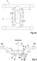
- Figure 4a discloses the bogie frame 11 of figure 4 showing the line of a cross section A-A.
- Figure 5 shows the cross section A-A of figure 4a .
- the longitudinal beam 3a is cranked on each end 30a and 30b in the height direction H, such that attachment section 33 is lower than the ends 30a and 30b.
- the anti-roll stabilizer systems 60 are attached to the underside of cross beams 4a and 4b (see Fig. 2 ) by connection elements 64, here back bearings, in particular rubber bushings.
- the connection elements 64 comprise two half parts 64a and 64b, between which the torsion rod 61 is arranged.
- the pendulum device 63 comprises a connector end 65 for connecting the anti-roll stabilizer system 60 to a connector on a bolster or a car body. Between pendulum device 63 and torsion rod 61 there is lever device 62.
- Figure 6 shows a cross section of the pin 44a of the first frame part 1 attached to the longitudinal beam 3b of the second frame part 2.
- the pin 44a comprises a bearing section 48
- the bearing section 48 comprises a full profile. Alternatively, a thick walled pipe section is possible.
Landscapes
- Engineering & Computer Science (AREA)
- Mechanical Engineering (AREA)
- Chemical & Material Sciences (AREA)
- Combustion & Propulsion (AREA)
- Transportation (AREA)
- Vehicle Body Suspensions (AREA)
- Vibration Prevention Devices (AREA)
- Body Structure For Vehicles (AREA)
- Springs (AREA)
Description
- The invention relates to a bogie for a rail vehicle and a rail vehicle with a bogie.
- It is known that bogies used on uneven rail ways are subjected to a lot of stress. Thus, traditional bogies comprising a one-piece frame use primary suspensions with high flexibilities to counter these effects.
- However, these traditional bogies have been adapted to comprise two frame parts to allow for a stiffer primary suspension: From
US 2014 158 016 a bogie is known, which comprises two frame parts. This bogie comprises a spherical transom bearing. The drawback of this bogie is that as the two frame parts move relative to each other, the thrust of the movements are translated harshly. - The document
US 3,826,202 discloses a railway vehicle truck for supporting a car body comprising two longitudinally spaced wheel-axle units each including an axle and two transversely spaced wheels. - It is the object of the invention to solve the problems of the state of the art and in particular provide a bogie for a rail vehicle and a rail vehicle with a bogie with improved running characteristics, high flexibility against torsion and equal distribution of wheel load.
- This is achieved by a bogie for a rail vehicle comprising the technical features of appended
claim 1. - The flexible connection of the frame parts soften the thrust of the movements due to the twisting of the tracks and thereby provide a part of the function of the primary springs. Thus, the primary springs do not need to be as flexible and the spring deflection and rebound is reduced, such that the primary spring height can be reduced. Such a bogie provides a great advantage as collisions between the primary spring pot and the structure of the car body are prevented.
- The elastomeric element can comprise or consist of natural rubber (NR) and/or a synthetic rubber such as polychloroprene (CR) or nitrile rubber (NBR). The stiffness of the elastomeric element, in particular for an elastomeric flange bushing, can be
- C radial = 200-500kN/mm, preferably 500 kN/mm
- C axial = 200-500 kN/mm, preferably 250kN/mm
- C torsional = 0-2000 Nm/°, preferably 1500 Nm/°
- C cardanic = 0-15000Nm/°, preferably 12000 Nm/°.
- The cross beams and the longitudinal beams may comprise or may be made of cast steel, cast aluminum, nodular graphite cast iron, welded design or carbon fiber.
- The cross beam can be hollow section.
- The receptacle can be formed as an opening in the longitudinal beam, in particular an opening along an opening axis, wherein the axis is arranged in cross direction. The opening can be a borehole.
- Preferably, the cross beams are cranked on one end, in particular cranked at both ends, preferably both in the longitudinal direction, more preferably in opposite directions in the longitudinal direction, most preferably cranked away from each other.
- This allows for arranging the pins close to the middle of the length of the bogie, such that the tilt of the pins and the cardanic deformations are reduced and still the bogie frame provides enough space for further components of the bogie.
- Preferably, the elastomeric element is essentially cylindrical. Preferably, the elastomeric element can comprise two identical halves, each half having a flange, wherein the halves are connected to form a flange bushing such that the flanges are arranged on the outer sides on opposite sides of the cylindrical body in the middle.
- The advantage of this elastomeric element is that the element is stiff both in radial and axial directions, such that high forces are transferrable. Preferably, the identical halves are put on the pin such that the flanges are arranged opposite of each other. The flange on the outside is clamped by a covering element, which covering element is detachably connected to the cross beam and pre-stresses the elastomeric element. Such an element provides an axially and radially stiff and backlash-free connection; the connection also provides low torsion and cardanic stiffness. Preferably, the elastomeric element is connected to the cross beam, in particular the elastomeric element is screwed to the respective cross beam. The elastomeric element may be made of rubber, especially natural rubber.
- Preferably, the longitudinal beams are cranked, preferably in the height direction, in particular the middle part of the longitudinal beams is lower than the outer ends.
- The receptacle for receiving the cross beams in the respective longitudinal beam may be distanced from the middle of the length of the longitudinal beam by 150-400 mm, in particular 200-300 mm.
- This placement of the receptacle has the advantage of providing a well-balanced static wheel load. Additionally, the cardanic deflection of the elastomeric element is smaller the closer the receptacle is to the middle of the length of the longitudinal beam.
- Preferably, the bogie comprises at least one, preferably two, secondary springs, in particular pneumatic springs.
- The secondary springs may be distributed on the bogie such that the static load on each of the wheels of the bogie is equal. In particular, the pneumatic springs may be distributed in such a way as to compensate for the weight of components such as brakes or motor parts. The springs may be steel springs, rubber springs, hydraulic springs or a combination of two types of springs, such as hydropneumatic springs. The primary springs are of customary design.
- The bogie comprises two anti-roll stabilizer systems, one for each cross beam.
- Preferably, the anti-roll stabilizer system comprises at least one spring element, in particular a torsion rod.
- Preferably, the anti-roll stabilizer system comprises at least one, in particular two, pendulum device, the pendulum device in particular being connected to a lever device and connectable or connected to a car body of a rail vehicle or a bolster. The lever device is fixed on one end to the spring element and to the pendulum device on the other end. The spring element is fastened to the bogie frame in a way that allows for rotational movement of the spring element by at least one, preferably two, connection elements. The lever device can comprise a stop for restricting the upward movement of the lever. In particular, the connection elements are back bearings, in particular rubber bushings. The spring element may be supported by rubber bushings as connection elements. The rubber bushings may comprise two half shells or may be made in a single piece. In particular, the rubber bushing or each half shell may comprise one or more rubber layer. Additionally, the anti-roll stabilizer system may comprise a slide bearing for absorbing torsional movement by the torsion rod. This allows for an easy absorption of torsional movements.
- In particular, the distance of the anti-roll stabilizer system, in particular the spring element, from the middle of the length of the longitudinal beam is between 200mm and 500 mm, preferably 200mm-300mm.
- Such an anti-roll stabilizer system allows for securing the bogie to the car body in case of lifting the rail car or the traverse.
- The bogie comprises two anti-roll stabilizer systems, which are arranged symmetrically to a cross middle plane of the bogie, one on each frame part.
- This arrangement ensures an equal distribution of the wheel loads per bogie side even during roll of the vehicle. Preferably, the bogie comprises at least one, preferably four, connection elements for the anti-roll stabilizer systems, in particular two connection elements are arranged on each cross beam.
- This allows for an easy attachment of the anti-roll stabilizer system to the bogie frame.
- Preferably, the bogie comprises fastening elements, in particular brackets, for fastening further elements to the bogie frame. This allows for easy attachment of motors, brakes or other components to the bogie frame.
- Preferably, the bogie comprises brakes, particularly brakes attached to the longitudinal beams and/or the cross beams.
- Brakes attached to the longitudinal beams allow for enough space to attach further components like motors to the cross beams.
- The bogie can be a motorized bogie, in particular at least one motor, preferably two motors, is attached to one of, preferably each of, the cross beams.
- In particular, the motorized bogie comprises brakes attached to connection elements on the longitudinal beams.
- Preferably, the bogie comprises a gear support, wherein the gear support is arranged between the pin and the motor to the cross beam.
- This allows for reducing the movement of the coupling between motor and gears.
- The bogie can be a carrying bogie. In particular, the carrying bogie comprises brakes attached to the cross beams. The brake discs in this configuration can be attached to the axle. Depending on the brake power needed there can be one to four axle mounted brake discs.
- The problem is also solved by a rail vehicle comprising a car body and at least one bogie as previously described.
- Preferably, the rail vehicle comprises a bolster.
- Preferably, the rail vehicle comprises fasteners, in particular spherical bearings for connecting the rail vehicle to the anti-roll stabilizer system, in particular to the pendulum elements, the fasteners preferably being arranged on the bolster or on the car body.
- For maintenance, the rail vehicle including bogie needs to be lifted. The car body is lifted by means of lifting jacks and for lifting the bogie, usually two to four ropes are needed, which are attached to the bogie. The connectors of the rail vehicle allow for lifting up the rail vehicle including the bogie without further means such as ropes.
- In particular, the rail vehicle comprises two anti-roll stabilizer systems per bogie, which are arranged symmetrically to a cross middle plane through the bogie and are connected to the car body or to the bolster.
- This allows for lifting up the rail vehicle including the bogie without further measures to stabilize the bogie, as the transmission of force is realized through the pendulum devices and the stop at the lever of the anti-roll stabilizer system.
- A railway vehicle according to the invention can comprise at least one motorized bogie as described before and at least one running bogie as described before wherein the distance between the effective middle points of the secondary springs of the motorized bogie is different from the effective middle points of the secondary springs of the running bogie.
- This optimizes the load distribution on all four wheels of each bogie.
- The invention will be described more precisely in the figures. The figures show:
- Figure 1:
- a perspective view of a motorized bogie,
- Figure 2:
- a perspective view of a frame part,
- Figure 3:
- a perspective view of a bogie frame,
- Figure 4:
- a perspective view of a bogie frame from below with anti-roll stabilizer systems,
- Figure 4a:
- a view of the bogie frame of
figure 4 with the line of a cross section A-A, - Figure 5:
- a cross section A-A of
figure 4a - Figure 6:
- a cross section of the attachment of the pin of the first frame part to the longitudinal beam of the second frame part,
- Figure 7:
- a side view of a flange bushing,
- Figure 8:
- a perspective view of a trailer bogie.
-
Figure 1 shows a perspective view of abogie 10. In this case thebogie 10 is a motorized bogie. Thebogie 10 comprises abogie frame 11, attached to which there are twosecondary springs 12, twowheel sets 13, one brake (not visible) perwheel 18, out of which twobrake disks 14 are visible, twomotors 15, twogears 16 and two anti-roll stabilizer systems 60 (seeFig. 4 ). Thebogie frame 11 comprises afirst frame part 1 and asecond frame part 2. Thefirst frame part 1 comprises alongitudinal beam 3a (seeFig. 2 ) and across beam 4a (seeFig. 2 ), thesecond frame part 2 comprises similarly alongitudinal beam 3b and across beam 4b (seeFig. 3 ). The wheel sets 13 are arranged between theframe parts longitudinal beams motor 15 is arranged between awheel set 13 and across beam cross beam gear 16 is connected to amotor 15 and awheel set 13. Eachgear 16 is fixed to thecross beam motor 15 andgear 16. The relative movement between themotor 15 and thegear 16 is taken over for example by a curved tooth coupling (not visible). Eachsecondary spring 12 is supported on thefirst frame part 1 or thesecond frame part 2, respectively. The positioning of thesecondary springs 12 is adapted to thebogie 10 to even out the load on thewheels 18 of the wheel set 13. As thebogie 10 does not comprise one fixed frame but twoframe parts wheel 18 of wheels sets 13 can differ and needs to be accounted for. The distance between the effective middle of thesecondary springs 12 relative to each other in the cross direction W (seeFig. 2 ) is therefore adapted to the needs of thebogie 10 and is between 1600mm and 2000mm in the present embodiment. -
Figure 2 shows a perspective view of thefirst frame part 1 offigure 1 . Theframe part 1 comprises alongitudinal beam 3a and across beam 4a. Thebeams - The
frame part 1 comprises a length in a longitudinal direction D, a width in a cross direction W and a height in a height direction H. The cross direction W is arranged perpendicular to the longitudinal direction D and the height direction H is arranged perpendicular to the longitudinal direction D and the cross direction W. - The
cross beam 4a comprises amiddle part 43, afirst end 40a and asecond end 40b. Themiddle part 43 is formed along a cross axis C, the cross axis C being parallel to the cross direction W. - The
cross beam 4a is fixedly attached to or is one piece with thelongitudinal beam 3a by thefirst end 40a. Thesecond end 40b comprises a pin 44 for attaching thesecond end 40b to thelongitudinal beam 3b of the second frame part 2 (seefigure 3 ). - Each
end straight section 42 and a crankedsection 41. Thestraight section 42 is formed along a straight axis S, the straight axis S being arranged parallel to the cross axis C of themiddle part 43. The crankedsection 41 is cranked in the longitudinal direction D. - The
longitudinal beam 3a comprises anattachment section 33 and two symmetricallyidentical arms 35 on opposite sides of theattachment section 33. Thearms 35 are arranged in opposite directions relative to a plane through a middle axis M, the middle axis M leading through the middle of the length of thelongitudinal beam 3a in the cross direction W. Thearms 35 comprise ends 30a and 30b. The ends 30a and 30b comprise each arest element 34 and a crankedelement 31. The crankedelements 31 are cranked in the height direction H. Theattachments section 33 is formed along the longitudinal axis L leading in the longitudinal direction D. Thecross beam 4a is attached to theattachment section 33. Further, theattachment section 33 comprises a receptacle 51 for thepin 44b of thesecond frame part 2. The receptacle 51 is a bore hole with an bore hole axis B which is arranged parallel to the middle axis M and is distanced to the middle axis M of thelongitudinal beam 3a at a distance of 200-300 mm. This allows for an equal distribution of the static wheel load. - The
frame part 1 comprises asupport 50 for the support of a secondary spring 12 (seeFig. 1 ). Thesupport 50 is arranged between the receptacle 51 and thecross beam 4a. Thesupport 50 comprises an essentially round surface on top in height direction H. -
Figure 3 shows abogie frame 11 in perspective view. Thebogie frame 11 comprises twoidentical frame parts frame part 1 has been previously described infigure 2 . Thepin 44a of thefirst frame part 1 is arranged in thereceptacle 51b of thesecond frame part 2. Thepin 44b of thesecond frame part 2 is arranged in thereceptacle 51a of thefirst frame part 1. -
Figure 4 shows abogie 10 in a perspective view from below. Thebogie 10 is atrailer bogie 10 corresponding to the bogie shown inFigure 8 . In this view the twoanti-roll stabilizer systems 60 are visible. Eachanti-roll stabilizer system 60 comprises atorsional rod 61, twolever devices 62, twopendulum devices 63. Furthermore, thetorsional rods 61 are fixed to thecross beams lever device 62 is fixed on one end to thetorsional rod 61 and to thependulum device 63 on the other end. Thetorsional rod 61 is fastened to the bogie frame in a way that allows for rotational movement of thetorsional rod 61 by at least one, preferably two,connection elements 64. Thelever device 62 comprises a stop (not visible) for restricting the upward movement of thelever device 62. In particular, theconnection elements 64 are back bearings, in particular rubber bushings. The torsional rod is supported by rubber bushings. The rubber bushings may comprise two half shells or may be made in a single piece. In particular, the rubber bushing or each half shell may comprise one or more rubber layer. The anti-roll stabilizer system can als be applied to amotorized bogie 10 as shown inFig. 1 . -
Figure 4a discloses thebogie frame 11 offigure 4 showing the line of a cross section A-A. -
Figure 5 shows the cross section A-A offigure 4a . Thelongitudinal beam 3a is cranked on eachend attachment section 33 is lower than theends anti-roll stabilizer systems 60 are attached to the underside ofcross beams Fig. 2 ) byconnection elements 64, here back bearings, in particular rubber bushings. Theconnection elements 64 comprise twohalf parts torsion rod 61 is arranged. Thependulum device 63 comprises aconnector end 65 for connecting theanti-roll stabilizer system 60 to a connector on a bolster or a car body. Betweenpendulum device 63 andtorsion rod 61 there islever device 62. -
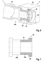
Figure 6 shows a cross section of thepin 44a of thefirst frame part 1 attached to thelongitudinal beam 3b of thesecond frame part 2. - The
pin 44a comprises abearing section 48 - The bearing
section 48 comprises a full profile. Alternatively, a thick walled pipe section is possible. - An
elastomeric element 45, here a flange bushing comprising two halves, is attached to thebearing section 48 and held into place by a coveringelement 46, which is screwed onto the end of thebearing section 48 of thepin 44a. The coveringelement 46 has alarger diameter 83 than the bearingsection 48 and therefore pre-stresses theelastomeric element 45. - The
pin 44a and theelastomeric element 45 rest in thereceptacle 51b of thesecond frame part 2. Thereceptacle 51b comprises two ledges to accommodate theelastomeric element 45. - Such a support of the
cross beam 4a inside thelongitudinal beam 3b allows for high flexibility against torsional movements and cardanic movements while simultaneously presenting a higher stiffness against radial or axial forces. -
Figure 7 shows theelastomeric element 45 in side view. Theelastomeric element 45 comprises twoidentical halves flange 90 and amiddle part 91. Themiddle parts 91 of theelastomeric element 45 are arranged such that they touch on their respective front sides. Theelastomeric element 45 comprises an elastomeric material with metal sheet layers for stabilization inside (not shown). The middle part and the flange can comprise one or more layers. - The
elastomeric element 45 is made of natural rubber with a stiffness C of:

- C torsional = 1500 Nm/°, torsional angles of up to 5° need to be possible,
- C cardanic = 12000 Nm/°, cardanic angles of up to 2° need to be possible,
-
Figure 8 shows a perspective view of abogie 10 in form of a trailer bogie. Thebogie 10 comprises abogie frame 11, attached to which there are twosecondary springs 12, twowheel sets 13, three brake calipers with brake disks per wheel set 13and two anti-stabilizer systems 60 (seeFig. 4 ). Thebogie frame 11 comprises afirst frame part 1 and asecond frame part 2. Thefirst frame part 1 comprises alongitudinal beam 3a (seeFig. 2 ) and across beam 4a (seeFig. 2 ), thesecond frame part 2 comprises similarly alongitudinal beam 3b and across beam 4b (seeFig. 3 ). The wheel sets 13 are arranged between theframe parts longitudinal beams secondary spring 12 is supported on thefirst frame part 1 or thesecond frame part 2, respectively. The positioning of thesecondary springs 12 is adapted to thebogie 10 to even out the load on the wheels of the wheel set 13. As thebogie 10 does not comprise one fixed frame but twoframe parts secondary springs 12 relative to each other in the cross direction W (seeFig. 2 ) is therefore adapted to the needs of thebogie 10 and is between 1600mm and 2000mm in the present embodiment. In particular the distance between the effective middle of thesecondary springs 12 of thetrailer bogie 10 can differ from the distance between the effective middle of the secondary springs of amotorized bogie 10 according toFig. 1 .
Claims (12)
- Bogie (10) for a rail vehicle, comprising a bogie frame (11) and at least four wheels (18), which are arranged at the bogie frame (11), wherein the bogie frame (11) comprises a length in a longitudinal direction (D), a width in a cross direction (C) to this longitudinal direction (D) and a height in a height direction (H), which is perpendicular to both the longitudinal direction (D) and the cross direction (C), wherein the bogie frame (11) comprises a first and a second frame part (1,2), each frame part (1,2) comprising a longitudinal beam (3a, 3b) and a cross beam (4a, 4b), wherein the cross beams (4a, 4b) each comprise a first end (40a) and a second end (40b), wherein each cross beam (4a, 4b) is fixedly attached at the first end (40a) to the respective longitudinal beam (3a, 3b), wherein each cross beam (4a, 4b) comprises a pin (44a, 44b) at the second end (40b), wherein the longitudinal beam (3a) of the first frame part (1) comprises a receptacle (51a) for the pin (44b) of the second frame part (2) and the longitudinal beam (3b) of the second frame part (2) comprises a receptacle (51b) for the pin (44a) of the first frame part (1), wherein an at least partially elastomeric element (45), in particular an elastomeric flange bushing, is fixed to each of the cross beams (4a, 4b) respectively, in particular to the pin (44a, 44b), characterized in that the bogie (10) comprises two anti-roll stabilizer systems (60), which are arranged symmetrically to a cross middle plane of the bogie (10), one on each frame part (1,2).
- Bogie (10) according to claim 1, characterized in that the cross beams (4a, 4b) are cranked on one end (40a, 40b), in particular cranked at both ends (40a, 40b), preferably both in the longitudinal direction (D), and in particular the longitudinal beams (3a, 3b) are cranked, preferably in the height direction (H), in particular the middle part (33) of the longitudinal beams (3a,3b) is lower than the outer ends (30a, 30b).
- Bogie (10) according to claim 1 or 2, characterized in that the elastomeric element (45) is essentially cylindrical, preferably the elastomeric element (45) comprises two identical halves (45a, 45b), each half (45a, 45b) having a flange (90), wherein the halves (45a, 45b) are connected to form a flange bushing.
- Bogie (10) according to one of the preceding claims, characterized in that the receptacle (51a, 51b) for receiving the cross beams (4a, 4b) in the respective longitudinal beam (3a, 3b) is distanced from the middle of the length of the longitudinal beam by 150-400 mm, in particular 200-300 mm.
- Bogie (10) according to one of the preceding claims, characterized in that the anti-roll stabilizer system (60) comprises at least one spring element (61), in particular a torsion rod, the spring element (61) being connectable or connected to connection elements (64).
- Bogie (10) according to one of the preceding claims, characterized in that the bogie (10) comprises at least one, preferably four, connection elements (64) for two anti-roll stabilizer systems (60), in particular two connection elements (64) are arranged on each cross beam (4a, 4b), the spring element (61) being connectable or connected to the connection elements (64).
- Bogie (10) according to one of the preceding claims, characterized in that the bogie (10) comprises brakes (14), particularly brakes (14) attached to the longitudinal beams (3a, 3b) and/or the cross beams (4a, 4b).
- Bogie (10) according to one of the preceding claims, characterized in that the bogie (10) is a motorized bogie, in particular at least one motor (15) is attached to one of the cross beams (4a, 4b).
- Bogie (10) according to claim 8, characterized in that the bogie (10) comprises a gear support, wherein the gear support is arranged between the pin (44a) and the attachment of the motor (15).
- Bogie (10) according to one of the claims 1-9, characterized in that the bogie (10) is a carrying bogie.
- Rail vehicle comprising a car body and at least one bogie (10) according to one of the previous claims.
- Rail vehicle according to claim 11 comprising connectors for connecting the rail vehicle to the anti-roll stabilizer systems (60), the connectors preferably being arranged on the bolster or on the car body.
Priority Applications (3)
| Application Number | Priority Date | Filing Date | Title |
|---|---|---|---|
| EP20204171.1A EP3992053B1 (en) | 2020-10-27 | 2020-10-27 | Bogie for a rail vehicle and rail vehicle with a bogie |
| CA3133516A CA3133516C (en) | 2020-10-27 | 2021-10-07 | Bogie for a rail vehicle and rail vehicle with a bogie |
| US17/502,336 US12325455B2 (en) | 2020-10-27 | 2021-10-15 | Bogie for a rail vehicle and rail vehicle with a bogie |
Applications Claiming Priority (1)
| Application Number | Priority Date | Filing Date | Title |
|---|---|---|---|
| EP20204171.1A EP3992053B1 (en) | 2020-10-27 | 2020-10-27 | Bogie for a rail vehicle and rail vehicle with a bogie |
Publications (3)
| Publication Number | Publication Date |
|---|---|
| EP3992053A1 EP3992053A1 (en) | 2022-05-04 |
| EP3992053B1 true EP3992053B1 (en) | 2025-07-02 |
| EP3992053C0 EP3992053C0 (en) | 2025-07-02 |
Family
ID=73029956
Family Applications (1)
| Application Number | Title | Priority Date | Filing Date |
|---|---|---|---|
| EP20204171.1A Active EP3992053B1 (en) | 2020-10-27 | 2020-10-27 | Bogie for a rail vehicle and rail vehicle with a bogie |
Country Status (3)
| Country | Link |
|---|---|
| US (1) | US12325455B2 (en) |
| EP (1) | EP3992053B1 (en) |
| CA (1) | CA3133516C (en) |
Families Citing this family (1)
| Publication number | Priority date | Publication date | Assignee | Title |
|---|---|---|---|---|
| CN114954551B (en) * | 2022-08-02 | 2022-11-18 | 秦皇岛优益创联特种车辆制造有限公司 | Power bogie of highway-railway transport vehicle |
Family Cites Families (10)
| Publication number | Priority date | Publication date | Assignee | Title |
|---|---|---|---|---|
| US3826202A (en) * | 1973-03-12 | 1974-07-30 | Budd Co | Pneumatically sprung railway car truck |
| US4570544A (en) * | 1982-06-16 | 1986-02-18 | Urban Transportation Development Corp. Ltd. | Diagonally braced rail truck |
| DE202008007471U1 (en) * | 2008-05-30 | 2008-12-11 | Vecon Trading & Engineering | Bogie with engine-gearbox-clutch unit |
| JP4685921B2 (en) * | 2008-12-26 | 2011-05-18 | 株式会社日立製作所 | Railcar bogie |
| CN102753418B (en) * | 2010-02-15 | 2015-04-01 | 日本车辆制造株式会社 | Bogie frame for railroad vehicle |
| CN102556097B (en) * | 2011-01-01 | 2014-07-30 | 齐齐哈尔轨道交通装备有限责任公司 | Central suspension device and high-speed truck bogie with same |
| JP5765292B2 (en) * | 2012-05-21 | 2015-08-19 | 新日鐵住金株式会社 | Bogie frame for railway vehicles |
| US9221475B2 (en) | 2012-07-11 | 2015-12-29 | Roller Bearing Company Of America, Inc. | Self lubricated spherical transom bearing |
| CN104325991A (en) * | 2014-11-13 | 2015-02-04 | 南车株洲电力机车有限公司 | Rail vehicle and hinged bogie for same |
| CN108791325B (en) * | 2018-07-27 | 2020-08-21 | 中车株洲电力机车有限公司 | Permanent-magnet direct-drive bogie and railway vehicle thereof |
-
2020
- 2020-10-27 EP EP20204171.1A patent/EP3992053B1/en active Active
-
2021
- 2021-10-07 CA CA3133516A patent/CA3133516C/en active Active
- 2021-10-15 US US17/502,336 patent/US12325455B2/en active Active
Also Published As
| Publication number | Publication date |
|---|---|
| CA3133516C (en) | 2025-09-09 |
| CA3133516A1 (en) | 2022-04-27 |
| US12325455B2 (en) | 2025-06-10 |
| EP3992053A1 (en) | 2022-05-04 |
| EP3992053C0 (en) | 2025-07-02 |
| US20220144322A1 (en) | 2022-05-12 |
Similar Documents
| Publication | Publication Date | Title |
|---|---|---|
| US8371234B2 (en) | Bogie for railway vehicle | |
| US5564521A (en) | Torque rod assembly | |
| CA1102831A (en) | Axle suspension for wheeled vehicles | |
| US3572745A (en) | Multiple axle suspension | |
| US5996981A (en) | Reduced size bushing for beam-type axle suspension system | |
| US8136455B2 (en) | Primary suspension device for a railway vehicle bogie | |
| US3856325A (en) | Multiple axle vehicle suspension system | |
| US3777672A (en) | Railway car suspension | |
| US4362109A (en) | Railway vehicle trucks | |
| WO1996030223A1 (en) | Large dump truck suspension | |
| RU2632055C2 (en) | Railway vehicle spring-mounting | |
| US7246808B2 (en) | Wheel suspension for vehicles | |
| GB2249763A (en) | Tandem wheel and axle suspension | |
| SK12393A3 (en) | Bogie for high-speed railway vehicle | |
| US3895819A (en) | Single axle suspension system | |
| US12325455B2 (en) | Bogie for a rail vehicle and rail vehicle with a bogie | |
| CA2281728A1 (en) | Rail vehicle with coupling element unit between the body of the wagon and the chassis | |
| EP0879750B1 (en) | Improvements in bogie trucks for rail vehicles | |
| EP0684404B1 (en) | Articulation arrangement for reaction rods | |
| US20050121874A1 (en) | Frame rail torsion attenuator | |
| FI85249B (en) | BOGGIE FOER JAERNVAEGSVAGNAR MED TIPPBAR STOMME. | |
| CN116476884A (en) | Primary rubber spring for metro vehicle | |
| JPH0321380B2 (en) | ||
| US20230166777A1 (en) | Bogie for a railway vehicle with roll stabiliser | |
| EP0334418A1 (en) | Bogie for passenger railway carriages with the floor at platform level throughout the carriage |
Legal Events
| Date | Code | Title | Description |
|---|---|---|---|
| PUAI | Public reference made under article 153(3) epc to a published international application that has entered the european phase |
Free format text: ORIGINAL CODE: 0009012 |
|
| STAA | Information on the status of an ep patent application or granted ep patent |
Free format text: STATUS: THE APPLICATION HAS BEEN PUBLISHED |
|
| AK | Designated contracting states |
Kind code of ref document: A1 Designated state(s): AL AT BE BG CH CY CZ DE DK EE ES FI FR GB GR HR HU IE IS IT LI LT LU LV MC MK MT NL NO PL PT RO RS SE SI SK SM TR |
|
| STAA | Information on the status of an ep patent application or granted ep patent |
Free format text: STATUS: REQUEST FOR EXAMINATION WAS MADE |
|
| 17P | Request for examination filed |
Effective date: 20220822 |
|
| RBV | Designated contracting states (corrected) |
Designated state(s): AL AT BE BG CH CY CZ DE DK EE ES FI FR GB GR HR HU IE IS IT LI LT LU LV MC MK MT NL NO PL PT RO RS SE SI SK SM TR |
|
| STAA | Information on the status of an ep patent application or granted ep patent |
Free format text: STATUS: EXAMINATION IS IN PROGRESS |
|
| 17Q | First examination report despatched |
Effective date: 20231024 |
|
| GRAP | Despatch of communication of intention to grant a patent |
Free format text: ORIGINAL CODE: EPIDOSNIGR1 |
|
| STAA | Information on the status of an ep patent application or granted ep patent |
Free format text: STATUS: GRANT OF PATENT IS INTENDED |
|
| INTG | Intention to grant announced |
Effective date: 20250130 |
|
| GRAS | Grant fee paid |
Free format text: ORIGINAL CODE: EPIDOSNIGR3 |
|
| GRAA | (expected) grant |
Free format text: ORIGINAL CODE: 0009210 |
|
| STAA | Information on the status of an ep patent application or granted ep patent |
Free format text: STATUS: THE PATENT HAS BEEN GRANTED |
|
| AK | Designated contracting states |
Kind code of ref document: B1 Designated state(s): AL AT BE BG CH CY CZ DE DK EE ES FI FR GB GR HR HU IE IS IT LI LT LU LV MC MK MT NL NO PL PT RO RS SE SI SK SM TR |
|
| REG | Reference to a national code |
Ref country code: GB Ref legal event code: FG4D |
|
| REG | Reference to a national code |
Ref country code: CH Ref legal event code: EP |
|
| REG | Reference to a national code |
Ref country code: DE Ref legal event code: R096 Ref document number: 602020053702 Country of ref document: DE |
|
| REG | Reference to a national code |
Ref country code: IE Ref legal event code: FG4D |
|
| U01 | Request for unitary effect filed |
Effective date: 20250721 |
|
| U07 | Unitary effect registered |
Designated state(s): AT BE BG DE DK EE FI FR IT LT LU LV MT NL PT RO SE SI Effective date: 20250728 |
|
| U20 | Renewal fee for the european patent with unitary effect paid |
Year of fee payment: 6 Effective date: 20250828 |
|
| REG | Reference to a national code |
Ref country code: CH Ref legal event code: U11 Free format text: ST27 STATUS EVENT CODE: U-0-0-U10-U11 (AS PROVIDED BY THE NATIONAL OFFICE) Effective date: 20251101 |
|
| PG25 | Lapsed in a contracting state [announced via postgrant information from national office to epo] |
Ref country code: IS Free format text: LAPSE BECAUSE OF FAILURE TO SUBMIT A TRANSLATION OF THE DESCRIPTION OR TO PAY THE FEE WITHIN THE PRESCRIBED TIME-LIMIT Effective date: 20251102 |
|
| PG25 | Lapsed in a contracting state [announced via postgrant information from national office to epo] |
Ref country code: NO Free format text: LAPSE BECAUSE OF FAILURE TO SUBMIT A TRANSLATION OF THE DESCRIPTION OR TO PAY THE FEE WITHIN THE PRESCRIBED TIME-LIMIT Effective date: 20251002 |
|
| PG25 | Lapsed in a contracting state [announced via postgrant information from national office to epo] |
Ref country code: HR Free format text: LAPSE BECAUSE OF FAILURE TO SUBMIT A TRANSLATION OF THE DESCRIPTION OR TO PAY THE FEE WITHIN THE PRESCRIBED TIME-LIMIT Effective date: 20250702 |
|
| PG25 | Lapsed in a contracting state [announced via postgrant information from national office to epo] |
Ref country code: GR Free format text: LAPSE BECAUSE OF FAILURE TO SUBMIT A TRANSLATION OF THE DESCRIPTION OR TO PAY THE FEE WITHIN THE PRESCRIBED TIME-LIMIT Effective date: 20251003 |
|
| PGFP | Annual fee paid to national office [announced via postgrant information from national office to epo] |
Ref country code: CH Payment date: 20251101 Year of fee payment: 6 |
|
| PG25 | Lapsed in a contracting state [announced via postgrant information from national office to epo] |
Ref country code: CZ Free format text: LAPSE BECAUSE OF FAILURE TO SUBMIT A TRANSLATION OF THE DESCRIPTION OR TO PAY THE FEE WITHIN THE PRESCRIBED TIME-LIMIT Effective date: 20250702 |
|
| PG25 | Lapsed in a contracting state [announced via postgrant information from national office to epo] |
Ref country code: PL Free format text: LAPSE BECAUSE OF FAILURE TO SUBMIT A TRANSLATION OF THE DESCRIPTION OR TO PAY THE FEE WITHIN THE PRESCRIBED TIME-LIMIT Effective date: 20250702 |
|
| PG25 | Lapsed in a contracting state [announced via postgrant information from national office to epo] |
Ref country code: RS Free format text: LAPSE BECAUSE OF FAILURE TO SUBMIT A TRANSLATION OF THE DESCRIPTION OR TO PAY THE FEE WITHIN THE PRESCRIBED TIME-LIMIT Effective date: 20251002 |
|
| PG25 | Lapsed in a contracting state [announced via postgrant information from national office to epo] |
Ref country code: ES Free format text: LAPSE BECAUSE OF FAILURE TO SUBMIT A TRANSLATION OF THE DESCRIPTION OR TO PAY THE FEE WITHIN THE PRESCRIBED TIME-LIMIT Effective date: 20250702 |
|
| PG25 | Lapsed in a contracting state [announced via postgrant information from national office to epo] |
Ref country code: SM Free format text: LAPSE BECAUSE OF FAILURE TO SUBMIT A TRANSLATION OF THE DESCRIPTION OR TO PAY THE FEE WITHIN THE PRESCRIBED TIME-LIMIT Effective date: 20250702 |
|
| PG25 | Lapsed in a contracting state [announced via postgrant information from national office to epo] |
Ref country code: SK Free format text: LAPSE BECAUSE OF FAILURE TO SUBMIT A TRANSLATION OF THE DESCRIPTION OR TO PAY THE FEE WITHIN THE PRESCRIBED TIME-LIMIT Effective date: 20250702 |
|
| PLBE | No opposition filed within time limit |
Free format text: ORIGINAL CODE: 0009261 |
|
| STAA | Information on the status of an ep patent application or granted ep patent |
Free format text: STATUS: NO OPPOSITION FILED WITHIN TIME LIMIT |