EP3992006B1 - Vehicle drive apparatus - Google Patents
Vehicle drive apparatus Download PDFInfo
- Publication number
- EP3992006B1 EP3992006B1 EP19934352.6A EP19934352A EP3992006B1 EP 3992006 B1 EP3992006 B1 EP 3992006B1 EP 19934352 A EP19934352 A EP 19934352A EP 3992006 B1 EP3992006 B1 EP 3992006B1
- Authority
- EP
- European Patent Office
- Prior art keywords
- gear
- clutch
- plane
- motor
- travel
- Prior art date
- Legal status (The legal status is an assumption and is not a legal conclusion. Google has not performed a legal analysis and makes no representation as to the accuracy of the status listed.)
- Active
Links
Images

Classifications
-
- B—PERFORMING OPERATIONS; TRANSPORTING
- B60—VEHICLES IN GENERAL
- B60K—ARRANGEMENT OR MOUNTING OF PROPULSION UNITS OR OF TRANSMISSIONS IN VEHICLES; ARRANGEMENT OR MOUNTING OF PLURAL DIVERSE PRIME-MOVERS IN VEHICLES; AUXILIARY DRIVES FOR VEHICLES; INSTRUMENTATION OR DASHBOARDS FOR VEHICLES; ARRANGEMENTS IN CONNECTION WITH COOLING, AIR INTAKE, GAS EXHAUST OR FUEL SUPPLY OF PROPULSION UNITS IN VEHICLES
- B60K6/00—Arrangement or mounting of plural diverse prime-movers for mutual or common propulsion, e.g. hybrid propulsion systems comprising electric motors and internal combustion engines
- B60K6/20—Arrangement or mounting of plural diverse prime-movers for mutual or common propulsion, e.g. hybrid propulsion systems comprising electric motors and internal combustion engines the prime-movers consisting of electric motors and internal combustion engines, e.g. HEVs
- B60K6/50—Architecture of the driveline characterised by arrangement or kind of transmission units
- B60K6/54—Transmission for changing ratio
- B60K6/547—Transmission for changing ratio the transmission being a stepped gearing
-
- B—PERFORMING OPERATIONS; TRANSPORTING
- B60—VEHICLES IN GENERAL
- B60K—ARRANGEMENT OR MOUNTING OF PROPULSION UNITS OR OF TRANSMISSIONS IN VEHICLES; ARRANGEMENT OR MOUNTING OF PLURAL DIVERSE PRIME-MOVERS IN VEHICLES; AUXILIARY DRIVES FOR VEHICLES; INSTRUMENTATION OR DASHBOARDS FOR VEHICLES; ARRANGEMENTS IN CONNECTION WITH COOLING, AIR INTAKE, GAS EXHAUST OR FUEL SUPPLY OF PROPULSION UNITS IN VEHICLES
- B60K6/00—Arrangement or mounting of plural diverse prime-movers for mutual or common propulsion, e.g. hybrid propulsion systems comprising electric motors and internal combustion engines
- B60K6/20—Arrangement or mounting of plural diverse prime-movers for mutual or common propulsion, e.g. hybrid propulsion systems comprising electric motors and internal combustion engines the prime-movers consisting of electric motors and internal combustion engines, e.g. HEVs
- B60K6/22—Arrangement or mounting of plural diverse prime-movers for mutual or common propulsion, e.g. hybrid propulsion systems comprising electric motors and internal combustion engines the prime-movers consisting of electric motors and internal combustion engines, e.g. HEVs characterised by apparatus, components or means specially adapted for HEVs
- B60K6/36—Arrangement or mounting of plural diverse prime-movers for mutual or common propulsion, e.g. hybrid propulsion systems comprising electric motors and internal combustion engines the prime-movers consisting of electric motors and internal combustion engines, e.g. HEVs characterised by apparatus, components or means specially adapted for HEVs characterised by the transmission gearings
-
- B—PERFORMING OPERATIONS; TRANSPORTING
- B60—VEHICLES IN GENERAL
- B60K—ARRANGEMENT OR MOUNTING OF PROPULSION UNITS OR OF TRANSMISSIONS IN VEHICLES; ARRANGEMENT OR MOUNTING OF PLURAL DIVERSE PRIME-MOVERS IN VEHICLES; AUXILIARY DRIVES FOR VEHICLES; INSTRUMENTATION OR DASHBOARDS FOR VEHICLES; ARRANGEMENTS IN CONNECTION WITH COOLING, AIR INTAKE, GAS EXHAUST OR FUEL SUPPLY OF PROPULSION UNITS IN VEHICLES
- B60K6/00—Arrangement or mounting of plural diverse prime-movers for mutual or common propulsion, e.g. hybrid propulsion systems comprising electric motors and internal combustion engines
- B60K6/20—Arrangement or mounting of plural diverse prime-movers for mutual or common propulsion, e.g. hybrid propulsion systems comprising electric motors and internal combustion engines the prime-movers consisting of electric motors and internal combustion engines, e.g. HEVs
- B60K6/22—Arrangement or mounting of plural diverse prime-movers for mutual or common propulsion, e.g. hybrid propulsion systems comprising electric motors and internal combustion engines the prime-movers consisting of electric motors and internal combustion engines, e.g. HEVs characterised by apparatus, components or means specially adapted for HEVs
- B60K6/38—Arrangement or mounting of plural diverse prime-movers for mutual or common propulsion, e.g. hybrid propulsion systems comprising electric motors and internal combustion engines the prime-movers consisting of electric motors and internal combustion engines, e.g. HEVs characterised by apparatus, components or means specially adapted for HEVs characterised by the driveline clutches
- B60K6/387—Actuated clutches, i.e. clutches engaged or disengaged by electric, hydraulic or mechanical actuating means
-
- B—PERFORMING OPERATIONS; TRANSPORTING
- B60—VEHICLES IN GENERAL
- B60K—ARRANGEMENT OR MOUNTING OF PROPULSION UNITS OR OF TRANSMISSIONS IN VEHICLES; ARRANGEMENT OR MOUNTING OF PLURAL DIVERSE PRIME-MOVERS IN VEHICLES; AUXILIARY DRIVES FOR VEHICLES; INSTRUMENTATION OR DASHBOARDS FOR VEHICLES; ARRANGEMENTS IN CONNECTION WITH COOLING, AIR INTAKE, GAS EXHAUST OR FUEL SUPPLY OF PROPULSION UNITS IN VEHICLES
- B60K6/00—Arrangement or mounting of plural diverse prime-movers for mutual or common propulsion, e.g. hybrid propulsion systems comprising electric motors and internal combustion engines
- B60K6/20—Arrangement or mounting of plural diverse prime-movers for mutual or common propulsion, e.g. hybrid propulsion systems comprising electric motors and internal combustion engines the prime-movers consisting of electric motors and internal combustion engines, e.g. HEVs
- B60K6/22—Arrangement or mounting of plural diverse prime-movers for mutual or common propulsion, e.g. hybrid propulsion systems comprising electric motors and internal combustion engines the prime-movers consisting of electric motors and internal combustion engines, e.g. HEVs characterised by apparatus, components or means specially adapted for HEVs
- B60K6/40—Arrangement or mounting of plural diverse prime-movers for mutual or common propulsion, e.g. hybrid propulsion systems comprising electric motors and internal combustion engines the prime-movers consisting of electric motors and internal combustion engines, e.g. HEVs characterised by apparatus, components or means specially adapted for HEVs characterised by the assembly or relative disposition of components
-
- B—PERFORMING OPERATIONS; TRANSPORTING
- B60—VEHICLES IN GENERAL
- B60K—ARRANGEMENT OR MOUNTING OF PROPULSION UNITS OR OF TRANSMISSIONS IN VEHICLES; ARRANGEMENT OR MOUNTING OF PLURAL DIVERSE PRIME-MOVERS IN VEHICLES; AUXILIARY DRIVES FOR VEHICLES; INSTRUMENTATION OR DASHBOARDS FOR VEHICLES; ARRANGEMENTS IN CONNECTION WITH COOLING, AIR INTAKE, GAS EXHAUST OR FUEL SUPPLY OF PROPULSION UNITS IN VEHICLES
- B60K6/00—Arrangement or mounting of plural diverse prime-movers for mutual or common propulsion, e.g. hybrid propulsion systems comprising electric motors and internal combustion engines
- B60K6/20—Arrangement or mounting of plural diverse prime-movers for mutual or common propulsion, e.g. hybrid propulsion systems comprising electric motors and internal combustion engines the prime-movers consisting of electric motors and internal combustion engines, e.g. HEVs
- B60K6/42—Arrangement or mounting of plural diverse prime-movers for mutual or common propulsion, e.g. hybrid propulsion systems comprising electric motors and internal combustion engines the prime-movers consisting of electric motors and internal combustion engines, e.g. HEVs characterised by the architecture of the hybrid electric vehicle
- B60K6/44—Series-parallel type
- B60K6/442—Series-parallel switching type
-
- B—PERFORMING OPERATIONS; TRANSPORTING
- B60—VEHICLES IN GENERAL
- B60K—ARRANGEMENT OR MOUNTING OF PROPULSION UNITS OR OF TRANSMISSIONS IN VEHICLES; ARRANGEMENT OR MOUNTING OF PLURAL DIVERSE PRIME-MOVERS IN VEHICLES; AUXILIARY DRIVES FOR VEHICLES; INSTRUMENTATION OR DASHBOARDS FOR VEHICLES; ARRANGEMENTS IN CONNECTION WITH COOLING, AIR INTAKE, GAS EXHAUST OR FUEL SUPPLY OF PROPULSION UNITS IN VEHICLES
- B60K6/00—Arrangement or mounting of plural diverse prime-movers for mutual or common propulsion, e.g. hybrid propulsion systems comprising electric motors and internal combustion engines
- B60K6/20—Arrangement or mounting of plural diverse prime-movers for mutual or common propulsion, e.g. hybrid propulsion systems comprising electric motors and internal combustion engines the prime-movers consisting of electric motors and internal combustion engines, e.g. HEVs
- B60K6/42—Arrangement or mounting of plural diverse prime-movers for mutual or common propulsion, e.g. hybrid propulsion systems comprising electric motors and internal combustion engines the prime-movers consisting of electric motors and internal combustion engines, e.g. HEVs characterised by the architecture of the hybrid electric vehicle
- B60K6/48—Parallel type
- B60K2006/4833—Step up or reduction gearing driving generator, e.g. to operate generator in most efficient speed range
-
- B—PERFORMING OPERATIONS; TRANSPORTING
- B60—VEHICLES IN GENERAL
- B60Y—INDEXING SCHEME RELATING TO ASPECTS CROSS-CUTTING VEHICLE TECHNOLOGY
- B60Y2200/00—Type of vehicle
- B60Y2200/90—Vehicles comprising electric prime movers
- B60Y2200/92—Hybrid vehicles
-
- F—MECHANICAL ENGINEERING; LIGHTING; HEATING; WEAPONS; BLASTING
- F16—ENGINEERING ELEMENTS AND UNITS; GENERAL MEASURES FOR PRODUCING AND MAINTAINING EFFECTIVE FUNCTIONING OF MACHINES OR INSTALLATIONS; THERMAL INSULATION IN GENERAL
- F16H—GEARING
- F16H2200/00—Transmissions for multiple ratios
- F16H2200/003—Transmissions for multiple ratios characterised by the number of forward speeds
- F16H2200/0034—Transmissions for multiple ratios characterised by the number of forward speeds the gear ratios comprising two forward speeds
-
- F—MECHANICAL ENGINEERING; LIGHTING; HEATING; WEAPONS; BLASTING
- F16—ENGINEERING ELEMENTS AND UNITS; GENERAL MEASURES FOR PRODUCING AND MAINTAINING EFFECTIVE FUNCTIONING OF MACHINES OR INSTALLATIONS; THERMAL INSULATION IN GENERAL
- F16H—GEARING
- F16H3/00—Toothed gearings for conveying rotary motion with variable gear ratio or for reversing rotary motion
- F16H3/02—Toothed gearings for conveying rotary motion with variable gear ratio or for reversing rotary motion without gears having orbital motion
- F16H3/08—Toothed gearings for conveying rotary motion with variable gear ratio or for reversing rotary motion without gears having orbital motion exclusively or essentially with continuously meshing gears, that can be disengaged from their shafts
- F16H3/087—Toothed gearings for conveying rotary motion with variable gear ratio or for reversing rotary motion without gears having orbital motion exclusively or essentially with continuously meshing gears, that can be disengaged from their shafts characterised by the disposition of the gears
- F16H3/091—Toothed gearings for conveying rotary motion with variable gear ratio or for reversing rotary motion without gears having orbital motion exclusively or essentially with continuously meshing gears, that can be disengaged from their shafts characterised by the disposition of the gears including a single countershaft
-
- F—MECHANICAL ENGINEERING; LIGHTING; HEATING; WEAPONS; BLASTING
- F16—ENGINEERING ELEMENTS AND UNITS; GENERAL MEASURES FOR PRODUCING AND MAINTAINING EFFECTIVE FUNCTIONING OF MACHINES OR INSTALLATIONS; THERMAL INSULATION IN GENERAL
- F16H—GEARING
- F16H3/00—Toothed gearings for conveying rotary motion with variable gear ratio or for reversing rotary motion
- F16H3/02—Toothed gearings for conveying rotary motion with variable gear ratio or for reversing rotary motion without gears having orbital motion
- F16H3/08—Toothed gearings for conveying rotary motion with variable gear ratio or for reversing rotary motion without gears having orbital motion exclusively or essentially with continuously meshing gears, that can be disengaged from their shafts
- F16H3/12—Toothed gearings for conveying rotary motion with variable gear ratio or for reversing rotary motion without gears having orbital motion exclusively or essentially with continuously meshing gears, that can be disengaged from their shafts with means for synchronisation not incorporated in the clutches
- F16H3/126—Toothed gearings for conveying rotary motion with variable gear ratio or for reversing rotary motion without gears having orbital motion exclusively or essentially with continuously meshing gears, that can be disengaged from their shafts with means for synchronisation not incorporated in the clutches using an electric drive
-
- Y—GENERAL TAGGING OF NEW TECHNOLOGICAL DEVELOPMENTS; GENERAL TAGGING OF CROSS-SECTIONAL TECHNOLOGIES SPANNING OVER SEVERAL SECTIONS OF THE IPC; TECHNICAL SUBJECTS COVERED BY FORMER USPC CROSS-REFERENCE ART COLLECTIONS [XRACs] AND DIGESTS
- Y02—TECHNOLOGIES OR APPLICATIONS FOR MITIGATION OR ADAPTATION AGAINST CLIMATE CHANGE
- Y02T—CLIMATE CHANGE MITIGATION TECHNOLOGIES RELATED TO TRANSPORTATION
- Y02T10/00—Road transport of goods or passengers
- Y02T10/60—Other road transportation technologies with climate change mitigation effect
- Y02T10/62—Hybrid vehicles
Definitions
- the present invention relates to a vehicle drive apparatus.
- WO2013129011A1 discloses a vehicle drive apparatus in which the vehicle drive apparatus comprising an engine, a travel motor, an electric-power generator, and a gear box.
- JP 2018-134937 A discloses a transaxle device equipped with an engine, a first rotating electric machine for driving the output shaft on the driven wheel side, and a second rotating electric machine for generating electric power by the driving force of the engine.
- a driving power transmission path is for individually transmitting the power of the engine and the first rotating electrical machine to the output shaft.
- a power transmission path is for transmitting the power of the engine to the second rotating electric machine.
- the transaxle apparatus for a hybrid vehicle comprising: a parking gear provided on a first power transmission path from the first rotating electrical machine to the output shaft; and a disengaging mechanism provided on the first power transmission path and for disconnecting and connecting the power transmission of the rotary electric machine.
- the parking gear and the disengaging mechanism overlap each other in a direction orthogonal to the axial direction of the output shaft.
- the present invention provides a vehicle drive apparatus according to claim 1.
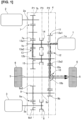
- FIG. 1 is a schematic diagram showing a vehicle drive apparatus according to a first embodiment.
- the vehicle in the first embodiment is a hybrid vehicle configured to travel by switching between a series scheme and a parallel scheme.
- the vehicle drive apparatus is provided with an engine (an internal combustion engine) 1, an electric-power-generating motor (a first rotary electrical machine) 2, a travel motor (a second rotary electrical machine) 3, a gear box 4, a driveshaft (a vehicle driveshaft) 5, and drive wheels 6.
- an engine an internal combustion engine
- an electric-power-generating motor a first rotary electrical machine
- a travel motor a second rotary electrical machine
- gear box 4 a driveshaft (a vehicle driveshaft) 5
- a plurality of gear trains an electric-power-generating-motor gear train 7, a travel-motor reduction mechanism 9, a differential (a second gear train) 10, and an engine shifting mechanism 11
- a crankshaft (an output shaft) 1a of the engine 1 is provided integrally with an input shaft 1b accommodated in the gear box 4.
- the input shaft 1b is connected to a motor shaft 2a of the electric-power-generating motor 2 via the electric-power-generating-motor gear train 7.
- the electric-power-generating-motor gear train (a first gear train) 7 has two gears 7a, 7b that mesh with each other.
- the drive gear 7a meshes with a drive gear (a first gear 13a1) secured to the input shaft 1b.
- the driven gear 7b is secured to the motor shaft 2a.
- a motor shaft 3a of the travel motor 3 can be coupled with a drive gear 9a1 of the travel-motor reduction mechanism 9 via a motor-travel clutch 8 accommodated in the gear box 4.
- the motor-travel clutch 8 is a dog clutch that does not have a rotation synchronization mechanism and is thereby engaged by a meshing stroke in a rotation-synchronized state.
- the travel-motor reduction mechanism 9 has a travel-motor gear train 9a and a travel-motor final reduction gear 9b.
- the travel-motor gear train 9a has two gears 9a1, 9a2 that mesh with each other.
- the drive gear 9a1 is a free-rotating gear that is rotatably supported on the motor shaft 3a.
- the driven gear 9a2 is secured to a rotating shaft 9c.
- the travel-motor final reduction gear 9b is secured to the rotating shaft 9c.
- the travel-motor final reduction gear 9b meshes with a ring gear 10a of the differential 10.
- the differential 10 is provided with a differential case 10b having an actuating mechanism unit (not shown) in the interior thereof.
- Left/right side gears of the actuating mechanism unit are coupled with left/right driveshafts 5.
- the left/right driveshafts 5 are coupled with the drive wheels 6.
- the engine shifting mechanism 11 is an automatic shifter configured to switch between a low-gear stage and a high-gear stage, and has a high-gear-stage gear train 12, a low-gear-stage gear train 13, a high clutch (a second clutch) 14, and a low clutch (a first clutch) 15.
- the high-gear-stage gear train 12 has two gears 12a1, 12a2 that mesh with each other.
- the drive gear (a third gear) 12a1 is a free-rotating gear that is rotatably supported on the input shaft 1b.
- the drive gear 12a1 can be coupled with the input shaft 1b via the high clutch 14.
- the driven gear (a fourth gear) 12a2 is secured to a countershaft 12b and meshes with the ring gear (a reduction large gear) 10a of the differential 10. Specifically, the driven gear 12a2 additionally serves as a reduction small gear (an engine final reduction gear) of a final reduction device.
- the low-gear-stage gear train 13 has two gears 13a1, 13a2 that mesh with each other.
- the driven gear (a second gear) 13a2 is a free-rotating gear that is rotatably supported on the countershaft 12b.
- the driven gear 13a2 can be coupled with the countershaft 12b via the low clutch 15.
- the low-gear-stage gear train 13 has a higher shift ratio than the high-gear-stage gear train 12.
- the high clutch 14 is a dog clutch that does not have a rotation synchronization mechanism and is thereby engaged by a meshing stroke in a rotation-synchronized state.
- a sleeve of the high clutch 14 When (a sleeve of) the high clutch 14 is at a right-side engagement position (right), the drive gear 12a1 and the input shaft 1b are coupled.
- the sleeve of) the high clutch 14 When (the sleeve of) the high clutch 14 is at a left-side release position (left), the drive gear 12a1 and the input shaft 1b are uncoupled.
- the engine shifting mechanism 11 reaches a high-gear stage due to the engagement of the drive gear 12a1 and the input shaft 1b.
- a path indicated by a single-dot chain line in Fig. 1 is a motive power propagation path extending from the engine 1 to the drive wheels 6.
- the low clutch 15 is a dog clutch that does not have a rotation synchronization mechanism and is thereby engaged by a meshing stroke in a rotation-synchronized state.
- a sleeve of the low clutch 15 When (a sleeve of) the low clutch 15 is at a left-side engagement position (left), the driven gear 13a2 and the countershaft 12b are coupled.
- the sleeve of) the low clutch 15 When (the sleeve of) the low clutch 15 is at a right-side release position (right), the driven gear 13a2 and the countershaft 12b are uncoupled.
- the engine shifting mechanism 11 reaches a low-gear stage due to the engagement of the driven gear 13a2 and the countershaft 12b.
- a path indicated by a dashed line in Fig. 1 is a motive power propagation path extending from the engine 1 to the drive wheels 6.
- Three planes P1, P2, P3 that extend in a direction orthogonal to an axial direction of the crankshaft 1a are established.
- the planes P1, P2, P3 are parallel to each other.
- the first plane P1 and the second plane P2 are positioned on the left and right sides, respectively, and the third plane P3 is positioned between the first plane P1 and the second plane P2.
- the electric-power-generating-motor gear train 7, the low-gear-stage gear train 13, and the travel-motor reduction mechanism 9 are arranged on the first plane P1.
- the high-gear-stage gear train 12 and the differential 10 are arranged on the second plane P2. (The sleeves of) the high clutch 14, the low clutch 15, and the motor-travel clutch 8 are arranged on the third plane P3.
- engaging the motor-travel clutch 8 and releasing both the high clutch 14 and the low clutch 15 effects travel under a series hybrid mode in which only the travel motor 3 is used as a motive power source for travel and the engine 1 is used as a motive power source for electric power generation.
- releasing the motor-travel clutch 8 and selectively engaging one of the high clutch 14 and the low clutch 15 effects travel under an engine direct coupling mode in which only the engine 1 is used as a motive power source for travel.
- the engine shifting mechanism 11 can switch between the low-gear stage and the high-gear stage in the engine direct coupling mode.
- engaging the motor-travel clutch 8 in a state where one of the high clutch 14 and the low clutch 15 has been engaged enables travel in a parallel hybrid mode.
- Figure 2 shows a comparative example for the first embodiment and is such that a shifting clutch 20 is arranged on one shaft (input shaft 1b) to configure a two-stage shifting transmission.
- the drive gear 12a1 of the high-gear-stage gear train 12 and the drive gear 13a1 of the low-gear-stage gear train 13 are free-rotating gears that are rotatably supported on the input shaft 1b.
- the shifting clutch 20 is a dog clutch and is arranged between the two drive gears 12a1, 13a1 in the axial direction of the crankshaft 1a.
- a gear 21 that meshes with the drive gear 7a of the electric-power-generating-motor gear train 7 is secured to the input shaft 1b.
- the driven gear 12a2 of the high-gear-stage gear train 12 and the driven gear 13a2 of the low-gear-stage gear train 13 are secured to the countershaft 12b.
- An engine final reduction gear 22 that meshes with the ring gear 10a of the differential 10 is also secured to the countershaft 12b.
- the shifting clutch is distributed on two shafts (input shaft 1b, countershaft 12b) as the high clutch 14 and the low clutch 15.
- the axial-direction dimension of the crankshaft 1a can be reduced and vehicle mounting properties can be improved to a greater extent than in the comparative example, which has a four-train arrangement. Because the number of rotating shafts is the same as in the comparative example, the dimension in a direction orthogonal to the crankshaft 1a does not increase even though the shifting clutch is distributed on two shafts.
- the driven gear 12a2 of the high-gear-stage gear train 12 meshes with the ring gear 10a of the differential 10.
- the driven gear 12a2 serves as both a driven gear of a (two-speed) gear train for a high shift ratio and a reduction small gear of a final reduction device.
- the reduction small gear of the final reduction device is instead provided separately from the driven gear 12a2
- four elements are lined up on the countershaft 12b.
- the driven gear 12a2 additionally serving as the reduction small gear, the number of elements lined up on the countershaft 12b is three, and it is possible to reduce the dimension of the axial-direction-dimension of the crankshaft 1a.
- the basic configuration of the second embodiment is the same as that in the first embodiment, and therefore only portions differing from those in the first embodiment are described.
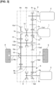
- FIG 3 is a schematic diagram showing a vehicle drive apparatus according to the second embodiment.
- the second embodiment differs from the first embodiment in that, inside the gear box 4: the electric-power-generating-motor gear train 7, the low-gear-stage gear train 13, and the travel-motor reduction mechanism 9 are arranged on a left side relative to (the sleeves of) the motor-travel clutch 8, the high clutch 14, and the low clutch 15; and the high-gear-stage gear train 12 and the differential 10 are arranged on a right side relative to (the sleeves of) the motor-travel clutch 8, the high clutch 14, and the low clutch 15.
- the electric-power-generating motor 2 and the travel motor 3 are arranged on the right side of the gear box 4.
- the positions of the first plane P1 and the second plane P2 in the second embodiment are opposite those in the first embodiment, and the first plane P1, the third plane P3, and the second plane P2 are lined up in the stated order from the right side.
- the second embodiment also exhibits the same effects as in the first embodiment.
- first gear and the second gear may form the low-gear-stage gear train
- the third gear and the fourth gear may form the high-gear-stage gear train
Landscapes
- Engineering & Computer Science (AREA)
- Chemical & Material Sciences (AREA)
- Combustion & Propulsion (AREA)
- Transportation (AREA)
- Mechanical Engineering (AREA)
- Hybrid Electric Vehicles (AREA)
- Structure Of Transmissions (AREA)
- Arrangement Of Transmissions (AREA)
Description
- The present invention relates to a vehicle drive apparatus.
-
WO2013129011A1 discloses a vehicle drive apparatus in which the vehicle drive apparatus comprising an engine, a travel motor, an electric-power generator, and a gear box. -
JP 2017-144993 A - an internal combustion engine;
- a first rotary electrical machine that is driven to generate electrical power by the internal combustion engine;
- a second rotary electrical machine that drives a vehicle driveshaft to rotate via a reducer;
- a first gear secured to an output shaft of the internal combustion engine;
- a first gear train that transfers rotation of the first gear to the first rotary electrical machine;
- a countershaft arranged parallel to the output shaft;
- a second gear that is rotatably supported on the countershaft and meshes with the first gear;
- a third gear that is rotatably supported on the output shaft;
- a fourth gear that is secured to the countershaft and meshes with the third gear;
- a second gear train that transfers rotation of the fourth gear to the vehicle driveshaft;
- a first clutch configured to engage the second gear with the countershaft; and
- a second clutch configured to engage the third gear with the output shaft;
- the first gear train and the second gear being arranged on a first plane that extends in a direction orthogonal to an axial direction of the output shaft,
- the third gear, the fourth gear, and the second gear train being arranged on a second plane that is set apart by a prescribed axial-direction distance from the first plane and that is parallel to the first plane, and
- the first clutch and the second clutch being arranged on a third plane that is parallel to the first plane and that is positioned between the first plane and the second plane.
-
JP 2018-134937 A - In the prior art described above, there was a necessity to reduce an axial-direction dimension of an output shaft in an internal combustion engine when adding a high/low two-speed gear shifting mechanism that is directly coupled with the output shaft. It is an object of the present invention to provide a vehicle drive apparatus in which it is possible to reduce an axial-direction dimension of an output shaft in an internal combustion engine.
- The present invention provides a vehicle drive apparatus according to
claim 1. - Thus, it is possible in the present invention to reduce an axial-direction dimension of an output shaft in an internal combustion engine.
-
-
Figure 1 is a schematic diagram showing a vehicle drive apparatus according to the first embodiment; -
Figure 2 is a schematic diagram showing a comparative example; and -
Figure 3 is a schematic diagram showing a vehicle drive apparatus according to the second embodiment. -
- 1
- Engine (internal combustion engine)
- 1a
- Crankshaft (output shaft)
- 2
- Electric-power-generating motor (first rotary electrical machine)
- 3
- Travel motor (second rotary electrical machine)
- 5
- Driveshaft (vehicle driveshaft)
- 7
- Electric-power-generating-motor gear train (first gear train)
- 10
- Differential (second gear train)
- 12
- High-gear-stage gear train
- 12a1
- Drive gear (third gear)
- 12a2
- Driven gear (fourth gear)
- 12b
- Countershaft
- 13
- Low-gear-stage gear train
- 13a1
- Drive gear (first gear)
- 13a2
- Driven gear (second gear)
- 14
- High clutch (second clutch)
- 15
- Low clutch (first clutch)
- P1
- First plane
- P2
- Second plane
- P3
- Third plane
-
Figure 1 is a schematic diagram showing a vehicle drive apparatus according to a first embodiment. The vehicle in the first embodiment is a hybrid vehicle configured to travel by switching between a series scheme and a parallel scheme. The vehicle drive apparatus is provided with an engine (an internal combustion engine) 1, an electric-power-generating motor (a first rotary electrical machine) 2, a travel motor (a second rotary electrical machine) 3, agear box 4, a driveshaft (a vehicle driveshaft) 5, and drivewheels 6. In thegear box 4, a plurality of gear trains (an electric-power-generating-motor gear train 7, a travel-motor reduction mechanism 9, a differential (a second gear train) 10, and an engine shifting mechanism 11) are accommodated inside a casing. - A crankshaft (an output shaft) 1a of the
engine 1 is provided integrally with aninput shaft 1b accommodated in thegear box 4. Theinput shaft 1b is connected to amotor shaft 2a of the electric-power-generatingmotor 2 via the electric-power-generating-motor gear train 7. The electric-power-generating-motor gear train (a first gear train) 7 has twogears drive gear 7a meshes with a drive gear (a first gear 13a1) secured to theinput shaft 1b. The drivengear 7b is secured to themotor shaft 2a. - A
motor shaft 3a of thetravel motor 3 can be coupled with a drive gear 9a1 of the travel-motor reduction mechanism 9 via a motor-travel clutch 8 accommodated in thegear box 4. The motor-travel clutch 8 is a dog clutch that does not have a rotation synchronization mechanism and is thereby engaged by a meshing stroke in a rotation-synchronized state. When (a sleeve of) the motor-travel clutch 8 is at a left-side engagement position (left), themotor shaft 3a and the drive gear 9a1 of the travel-motor reduction mechanism 9 are coupled. When (the sleeve of) the motor-travel clutch 8 is at a right-side release position (right), themotor shaft 3a and the drive gear 9a1 are uncoupled. - The travel-
motor reduction mechanism 9 has a travel-motor gear train 9a and a travel-motorfinal reduction gear 9b. The travel-motor gear train 9a has two gears 9a1, 9a2 that mesh with each other. The drive gear 9a1 is a free-rotating gear that is rotatably supported on themotor shaft 3a. The driven gear 9a2 is secured to arotating shaft 9c. The travel-motorfinal reduction gear 9b is secured to therotating shaft 9c. The travel-motorfinal reduction gear 9b meshes with aring gear 10a of the differential 10. In addition to thering gear 10a, the differential 10 is provided with adifferential case 10b having an actuating mechanism unit (not shown) in the interior thereof. Left/right side gears of the actuating mechanism unit are coupled with left/right driveshafts 5. The left/right driveshafts 5 are coupled with thedrive wheels 6. - The
engine shifting mechanism 11 is an automatic shifter configured to switch between a low-gear stage and a high-gear stage, and has a high-gear-stage gear train 12, a low-gear-stage gear train 13, a high clutch (a second clutch) 14, and a low clutch (a first clutch) 15. The high-gear-stage gear train 12 has two gears 12a1, 12a2 that mesh with each other. The drive gear (a third gear) 12a1 is a free-rotating gear that is rotatably supported on theinput shaft 1b. The drive gear 12a1 can be coupled with theinput shaft 1b via thehigh clutch 14. The driven gear (a fourth gear) 12a2 is secured to acountershaft 12b and meshes with the ring gear (a reduction large gear) 10a of the differential 10. Specifically, the driven gear 12a2 additionally serves as a reduction small gear (an engine final reduction gear) of a final reduction device. The low-gear-stage gear train 13 has two gears 13a1, 13a2 that mesh with each other. The driven gear (a second gear) 13a2 is a free-rotating gear that is rotatably supported on thecountershaft 12b. The driven gear 13a2 can be coupled with thecountershaft 12b via thelow clutch 15. The low-gear-stage gear train 13 has a higher shift ratio than the high-gear-stage gear train 12. - The
high clutch 14 is a dog clutch that does not have a rotation synchronization mechanism and is thereby engaged by a meshing stroke in a rotation-synchronized state. When (a sleeve of) thehigh clutch 14 is at a right-side engagement position (right), the drive gear 12a1 and theinput shaft 1b are coupled. When (the sleeve of) thehigh clutch 14 is at a left-side release position (left), the drive gear 12a1 and theinput shaft 1b are uncoupled. Theengine shifting mechanism 11 reaches a high-gear stage due to the engagement of the drive gear 12a1 and theinput shaft 1b. A path indicated by a single-dot chain line inFig. 1 is a motive power propagation path extending from theengine 1 to thedrive wheels 6. - The low clutch 15 is a dog clutch that does not have a rotation synchronization mechanism and is thereby engaged by a meshing stroke in a rotation-synchronized state. When (a sleeve of) the low clutch 15 is at a left-side engagement position (left), the driven gear 13a2 and the
countershaft 12b are coupled. When (the sleeve of) the low clutch 15 is at a right-side release position (right), the driven gear 13a2 and thecountershaft 12b are uncoupled. Theengine shifting mechanism 11 reaches a low-gear stage due to the engagement of the driven gear 13a2 and thecountershaft 12b. A path indicated by a dashed line inFig. 1 is a motive power propagation path extending from theengine 1 to thedrive wheels 6. - Three planes P1, P2, P3 that extend in a direction orthogonal to an axial direction of the
crankshaft 1a are established. The planes P1, P2, P3 are parallel to each other. The first plane P1 and the second plane P2 are positioned on the left and right sides, respectively, and the third plane P3 is positioned between the first plane P1 and the second plane P2. The electric-power-generating-motor gear train 7, the low-gear-stage gear train 13, and the travel-motor reduction mechanism 9 are arranged on the first plane P1. The high-gear-stage gear train 12 and the differential 10 are arranged on the second plane P2. (The sleeves of) thehigh clutch 14, the low clutch 15, and the motor-travel clutch 8 are arranged on the third plane P3. - In the vehicle in the first embodiment, engaging the motor-travel clutch 8 and releasing both the
high clutch 14 and the low clutch 15 effects travel under a series hybrid mode in which only thetravel motor 3 is used as a motive power source for travel and theengine 1 is used as a motive power source for electric power generation. In addition, releasing the motor-travel clutch 8 and selectively engaging one of thehigh clutch 14 and the low clutch 15 effects travel under an engine direct coupling mode in which only theengine 1 is used as a motive power source for travel. Theengine shifting mechanism 11 can switch between the low-gear stage and the high-gear stage in the engine direct coupling mode. In the vehicle in the first embodiment, engaging the motor-travel clutch 8 in a state where one of thehigh clutch 14 and the low clutch 15 has been engaged enables travel in a parallel hybrid mode. - Effects of the first embodiment are described next.
Figure 2 shows a comparative example for the first embodiment and is such that a shiftingclutch 20 is arranged on one shaft (input shaft 1b) to configure a two-stage shifting transmission. The drive gear 12a1 of the high-gear-stage gear train 12 and the drive gear 13a1 of the low-gear-stage gear train 13 are free-rotating gears that are rotatably supported on theinput shaft 1b. The shiftingclutch 20 is a dog clutch and is arranged between the two drive gears 12a1, 13a1 in the axial direction of thecrankshaft 1a. When (a sleeve of) the shiftingclutch 20 is at a left-side engagement position (left), the drive gear 12a1 and theinput shaft 1b are coupled, the drive gear 13a1 and theinput shaft 1b are uncoupled, and the high-gear stage is reached. When (the sleeve of) the shiftingclutch 20 is at a right-side engagement position (right), the drive gear 13a1 and theinput shaft 1b are coupled, the drive gear 12a1 and theinput shaft 1b are uncoupled, and the low-gear stage is reached. When (the sleeve of) the shiftingclutch 20 is at a central release position (N), the drive gear 12a1 and theinput shaft 1b are uncoupled, the drive gear 13a1 and theinput shaft 1b are uncoupled, and a neutral stage is achieved. - A
gear 21 that meshes with thedrive gear 7a of the electric-power-generating-motor gear train 7 is secured to theinput shaft 1b. The driven gear 12a2 of the high-gear-stage gear train 12 and the driven gear 13a2 of the low-gear-stage gear train 13 are secured to thecountershaft 12b. An enginefinal reduction gear 22 that meshes with thering gear 10a of the differential 10 is also secured to thecountershaft 12b. - When selectively switching gears directly coupled with the output shaft of the engine to configure a high/low two-speed transmission, in cases where the shifting
clutch 20 is arranged on one shaft (input shaft 1b) as in the comparative example, the two free-rotating gears (two drive gears 12a1, 13a1) and (the sleeve of) the shiftingclutch 20 are lined up on the one shaft. Furthermore, agear 21 for continuously driving the electric-power-generatingmotor 2 by means of theengine 1 must be provided on theinput shaft 1b. Specifically, in the comparative example, because there is a four-train arrangement in which four elements are lined up on one shaft, the axial-direction dimension of thecrankshaft 1a increases and vehicle mounting properties deteriorate. - However, in the drive apparatus in the first embodiment, the shifting clutch is distributed on two shafts (
input shaft 1b,countershaft 12b) as thehigh clutch 14 and thelow clutch 15. This makes it possible for the drive gear that is secured to theinput shaft 1b (drive gear 13a1 in the first embodiment), among the two drive gears 12a1, 13a1, to be used as a gear for continuously driving the electric-power-generatingmotor 2. Therefore, the number of elements lined up on each of theinput shaft 1b and thecountershaft 12b is three, and it is possible to realize a three-train arrangement. Thus, the axial-direction dimension of thecrankshaft 1a can be reduced and vehicle mounting properties can be improved to a greater extent than in the comparative example, which has a four-train arrangement. Because the number of rotating shafts is the same as in the comparative example, the dimension in a direction orthogonal to thecrankshaft 1a does not increase even though the shifting clutch is distributed on two shafts. - In the drive apparatus in the first embodiment, the driven gear 12a2 of the high-gear-
stage gear train 12 meshes with thering gear 10a of the differential 10. Specifically, the driven gear 12a2 serves as both a driven gear of a (two-speed) gear train for a high shift ratio and a reduction small gear of a final reduction device. In cases where the reduction small gear of the final reduction device is instead provided separately from the driven gear 12a2, four elements are lined up on thecountershaft 12b. However, due to the driven gear 12a2 additionally serving as the reduction small gear, the number of elements lined up on thecountershaft 12b is three, and it is possible to reduce the dimension of the axial-direction-dimension of thecrankshaft 1a. - The basic configuration of the second embodiment is the same as that in the first embodiment, and therefore only portions differing from those in the first embodiment are described.
-
Figure 3 is a schematic diagram showing a vehicle drive apparatus according to the second embodiment. The second embodiment differs from the first embodiment in that, inside the gear box 4: the electric-power-generating-motor gear train 7, the low-gear-stage gear train 13, and the travel-motor reduction mechanism 9 are arranged on a left side relative to (the sleeves of) the motor-travel clutch 8, thehigh clutch 14, and the low clutch 15; and the high-gear-stage gear train 12 and the differential 10 are arranged on a right side relative to (the sleeves of) the motor-travel clutch 8, thehigh clutch 14, and thelow clutch 15. The electric-power-generatingmotor 2 and thetravel motor 3 are arranged on the right side of thegear box 4. Thus, the positions of the first plane P1 and the second plane P2 in the second embodiment are opposite those in the first embodiment, and the first plane P1, the third plane P3, and the second plane P2 are lined up in the stated order from the right side. The second embodiment also exhibits the same effects as in the first embodiment. - A mode for carrying out the present invention has been described above on the basis of the embodiments, but the specific configuration of the present invention is not limited to these embodiments; design changes, etc., that do not depart from the scope of the invention are also included in the present invention as defined in the appended claims. For example, the first gear and the second gear may form the low-gear-stage gear train, and the third gear and the fourth gear may form the high-gear-stage gear train.
Claims (2)
- A vehicle drive apparatus comprising:an internal combustion engine (1);a first rotary electrical machine (2) that is driven to generate electrical power by the internal combustion engine (1);a second rotary electrical machine (3) that drives a vehicle driveshaft (5) to rotate via a reducer (9);a first gear (13a1) secured to an output shaft (1a) of the internal combustion engine (1);a first gear train (7) that transfers rotation of the first gear (13a1) to the first rotary electrical machine (2);a countershaft (12b) arranged parallel to the output shaft (1a);a second gear (13a2) that is rotatably supported on the countershaft (12b) and meshes with the first gear (13a1);a third gear (12a1) that is rotatably supported on the output shaft (1a);a fourth gear (12a2) that is secured to the countershaft (12b) and meshes with the third gear (12a1);a second gear train (10) that transfers rotation of the fourth gear (12a2) to the vehicle driveshaft (5);a first clutch (15) configured to engage the second gear (13a2) with the countershaft (12b); anda second clutch (14) configured to engage the third gear (12a1) with the output shaft (1a);a third clutch (8) configured to connect and disconnect propagation of a motive power between the second rotary electrical machine (3) and the reducer (9)the first gear train (7) and the second gear (13a2) being arranged on a first plane (P1) that extends in a direction orthogonal to an axial direction of the output shaft (1a),the third gear (12a1), the fourth gear (12a2), and the second gear train (10) being arranged on a second plane (P2) that is set apart by a prescribed axial-direction distance from the first plane (P1) and that is parallel to the first plane (P1), andthe first clutch (15) and the second clutch (14) being arranged on a third plane (P3) that is parallel to the first plane (P1) and that is positioned between the first plane (P1) and the second plane (P2);characterized in thatthe reducer (9) has a travel-motor gear train (9a) and a travel-motor final reduction gear (9b);the travel-motor gear train (9a) has a drive gear (9a1) and a driven gear (9a2) that mesh with each other;the drive gear (9a1) is a free-rotating gear that is rotatably supported on a motor shaft (3a) of the second rotary electrical machine (3);the driven gear (9a2) is secured to a rotating shaft (9c)the travel-motor final reduction gear (9b) is secured to the rotating shaft (9c);the travel-motor final reduction gear (9b) meshes with a ring gear (10a) of the second gear train (10).
- The vehicle drive apparatus according to claim 1, wherein
the fourth gear (12a2) is a reduction small gear that meshes with a reduction large gear (10a) in the second gear train (10).
Applications Claiming Priority (1)
| Application Number | Priority Date | Filing Date | Title |
|---|---|---|---|
| PCT/IB2019/000670 WO2020260916A1 (en) | 2019-06-26 | 2019-06-26 | Device for driving vehicle |
Publications (3)
| Publication Number | Publication Date |
|---|---|
| EP3992006A1 EP3992006A1 (en) | 2022-05-04 |
| EP3992006A4 EP3992006A4 (en) | 2022-06-08 |
| EP3992006B1 true EP3992006B1 (en) | 2024-05-22 |
Family
ID=74060479
Family Applications (1)
| Application Number | Title | Priority Date | Filing Date |
|---|---|---|---|
| EP19934352.6A Active EP3992006B1 (en) | 2019-06-26 | 2019-06-26 | Vehicle drive apparatus |
Country Status (5)
| Country | Link |
|---|---|
| US (1) | US11697339B2 (en) |
| EP (1) | EP3992006B1 (en) |
| JP (1) | JP7078179B2 (en) |
| CN (1) | CN114025979B (en) |
| WO (1) | WO2020260916A1 (en) |
Families Citing this family (8)
| Publication number | Priority date | Publication date | Assignee | Title |
|---|---|---|---|---|
| CN113829867B (en) * | 2021-09-23 | 2022-12-06 | 华为数字能源技术有限公司 | Hybrid power driving system and automobile |
| CN115027250A (en) * | 2022-06-30 | 2022-09-09 | 华为数字能源技术有限公司 | Hybrid power driving system, gearbox and vehicle |
| CN218228632U (en) * | 2022-07-27 | 2023-01-06 | 比亚迪股份有限公司 | Vehicle drive device and vehicle |
| FR3140026B1 (en) * | 2022-09-27 | 2026-04-24 | Renault Sas | Transmission for hybrid rear-wheel drive or front-wheel drive motor vehicles |
| US12435773B2 (en) * | 2023-06-16 | 2025-10-07 | Dana Belgium N.V. | Methods and systems of a two speed countershaft transmission |
| CN116811562A (en) * | 2023-07-03 | 2023-09-29 | 一汽解放汽车有限公司 | Electric drive bridge and vehicle |
| KR20250143943A (en) * | 2024-03-26 | 2025-10-10 | 현대트랜시스 주식회사 | Power transmission device for hybrid vehicle |
| KR20250143944A (en) * | 2024-03-26 | 2025-10-10 | 현대트랜시스 주식회사 | Power transmission device for hybrid vehicle |
Citations (1)
| Publication number | Priority date | Publication date | Assignee | Title |
|---|---|---|---|---|
| EP3453550A1 (en) * | 2016-06-13 | 2019-03-13 | Mitsubishi Jidosha Kogyo Kabushiki Kaisha | Transaxle device |
Family Cites Families (14)
| Publication number | Priority date | Publication date | Assignee | Title |
|---|---|---|---|---|
| JP2002199506A (en) * | 2000-12-22 | 2002-07-12 | Mazda Motor Corp | Hybrid drive |
| JP4151647B2 (en) * | 2004-12-14 | 2008-09-17 | 日産自動車株式会社 | Drive device for hybrid vehicle |
| DE112011101169T5 (en) * | 2010-03-31 | 2013-01-10 | Honda Motor Co., Ltd. | Vehicle drive system |
| JP5330362B2 (en) * | 2010-12-03 | 2013-10-30 | 本田技研工業株式会社 | Hybrid drive device |
| JP5900023B2 (en) | 2012-03-02 | 2016-04-06 | 三菱自動車工業株式会社 | Transaxle device for hybrid vehicles |
| EP2937237B1 (en) * | 2012-12-21 | 2021-08-11 | Nissan Motor Co., Ltd. | Hybrid vehicle drive device |
| EP3305615B1 (en) * | 2015-06-03 | 2019-09-25 | Nissan Motor Co., Ltd. | Mode transition control device for hybrid vehicle |
| JP2017032033A (en) * | 2015-07-30 | 2017-02-09 | アイシン・エィ・ダブリュ株式会社 | Drive unit for vehicle |
| US10807457B2 (en) * | 2016-06-13 | 2020-10-20 | Mitsubishi Jidosha Kogyo Kabushiki Kaisha | Transaxle device for hybrid vehicle having connection/disconnection mechanism that enables or disables transmission of power of electric machine |
| JP6819083B2 (en) * | 2016-06-13 | 2021-01-27 | 三菱自動車工業株式会社 | Transaxle device |
| WO2018037718A1 (en) | 2016-08-24 | 2018-03-01 | ジヤトコ株式会社 | Hybrid drive device and control method for hybrid drive device |
| CN109844367A (en) * | 2016-10-31 | 2019-06-04 | 爱信艾达株式会社 | Vehicle driving apparatus |
| JP6812835B2 (en) * | 2017-02-21 | 2021-01-13 | 三菱自動車工業株式会社 | Transaxle device |
| JP6319611B2 (en) | 2017-03-29 | 2018-05-09 | 三菱自動車工業株式会社 | Vehicle transaxle device |
-
2019
- 2019-06-26 US US17/621,712 patent/US11697339B2/en active Active
- 2019-06-26 WO PCT/IB2019/000670 patent/WO2020260916A1/en not_active Ceased
- 2019-06-26 CN CN201980097675.3A patent/CN114025979B/en active Active
- 2019-06-26 EP EP19934352.6A patent/EP3992006B1/en active Active
- 2019-06-26 JP JP2021528014A patent/JP7078179B2/en active Active
Patent Citations (1)
| Publication number | Priority date | Publication date | Assignee | Title |
|---|---|---|---|---|
| EP3453550A1 (en) * | 2016-06-13 | 2019-03-13 | Mitsubishi Jidosha Kogyo Kabushiki Kaisha | Transaxle device |
Also Published As
| Publication number | Publication date |
|---|---|
| CN114025979A (en) | 2022-02-08 |
| EP3992006A1 (en) | 2022-05-04 |
| JPWO2020260916A1 (en) | 2020-12-30 |
| US11697339B2 (en) | 2023-07-11 |
| US20220242222A1 (en) | 2022-08-04 |
| EP3992006A4 (en) | 2022-06-08 |
| JP7078179B2 (en) | 2022-05-31 |
| CN114025979B (en) | 2024-06-07 |
| WO2020260916A1 (en) | 2020-12-30 |
Similar Documents
| Publication | Publication Date | Title |
|---|---|---|
| EP3992006B1 (en) | Vehicle drive apparatus | |
| JP4572956B2 (en) | Vehicle drive device | |
| EP2322372B1 (en) | Hybrid propulsion system for a motor vehicle | |
| CN114930051A (en) | Power assembly for vehicle | |
| US9057428B2 (en) | Transaxle device | |
| CN112867620B (en) | Transmission and drive system for a motor vehicle | |
| KR102173459B1 (en) | Vehicles having a vehicle power drive system and a vehicle power drive system | |
| US10899219B2 (en) | Power drive system and vehicle | |
| US11485219B2 (en) | Transmission and drive system of a motor vehicle | |
| JP2021526107A (en) | Vertical multi-stage electrically driven power assembly | |
| EP3533677B1 (en) | Power train and vehicle having same | |
| US20210339619A1 (en) | Transmission and Drive System of a Motor Vehicle | |
| US10974591B2 (en) | Power transmission system and vehicle having same | |
| CN109070738A (en) | Vehicle drive system | |
| US20220144074A1 (en) | Hybrid power system | |
| CN113490610A (en) | Transmission assembly, motor vehicle powertrain and method of operating the same | |
| EP3476635A1 (en) | Power drive system and vehicle | |
| CN117355435A (en) | Hybrid transmission system for a motor vehicle | |
| CN107867171B (en) | Power driving system for vehicle and vehicle | |
| JPWO2018079842A1 (en) | Vehicle drive system | |
| EP3733437A1 (en) | Transmission, single-clutch powertrain system, and method for operating a single-clutch powertrain system | |
| US12012005B1 (en) | Hybrid system and vehicle | |
| WO2018079843A1 (en) | Vehicle drive transmission apparatus | |
| KR20230137384A (en) | Hybrid transmission, and drive train with hybrid transmission | |
| CN113898704B (en) | Two-speed electric bridge drive system and vehicle |
Legal Events
| Date | Code | Title | Description |
|---|---|---|---|
| STAA | Information on the status of an ep patent application or granted ep patent |
Free format text: STATUS: UNKNOWN |
|
| STAA | Information on the status of an ep patent application or granted ep patent |
Free format text: STATUS: THE INTERNATIONAL PUBLICATION HAS BEEN MADE |
|
| PUAI | Public reference made under article 153(3) epc to a published international application that has entered the european phase |
Free format text: ORIGINAL CODE: 0009012 |
|
| STAA | Information on the status of an ep patent application or granted ep patent |
Free format text: STATUS: REQUEST FOR EXAMINATION WAS MADE |
|
| 17P | Request for examination filed |
Effective date: 20220118 |
|
| AK | Designated contracting states |
Kind code of ref document: A1 Designated state(s): AL AT BE BG CH CY CZ DE DK EE ES FI FR GB GR HR HU IE IS IT LI LT LU LV MC MK MT NL NO PL PT RO RS SE SI SK SM TR |
|
| A4 | Supplementary search report drawn up and despatched |
Effective date: 20220511 |
|
| RIC1 | Information provided on ipc code assigned before grant |
Ipc: B60K 6/48 20071001ALN20220505BHEP Ipc: F16H 3/089 20060101ALI20220505BHEP Ipc: B60K 6/547 20071001ALI20220505BHEP Ipc: B60K 6/442 20071001ALI20220505BHEP Ipc: B60K 6/387 20071001ALI20220505BHEP Ipc: B60K 6/36 20071001ALI20220505BHEP Ipc: B60K 6/40 20071001AFI20220505BHEP |
|
| DAV | Request for validation of the european patent (deleted) | ||
| DAX | Request for extension of the european patent (deleted) | ||
| STAA | Information on the status of an ep patent application or granted ep patent |
Free format text: STATUS: EXAMINATION IS IN PROGRESS |
|
| 17Q | First examination report despatched |
Effective date: 20230627 |
|
| GRAP | Despatch of communication of intention to grant a patent |
Free format text: ORIGINAL CODE: EPIDOSNIGR1 |
|
| STAA | Information on the status of an ep patent application or granted ep patent |
Free format text: STATUS: GRANT OF PATENT IS INTENDED |
|
| RIC1 | Information provided on ipc code assigned before grant |
Ipc: B60K 6/48 20071001ALN20240220BHEP Ipc: F16H 3/12 20060101ALI20240220BHEP Ipc: F16H 3/091 20060101ALI20240220BHEP Ipc: F16H 3/089 20060101ALI20240220BHEP Ipc: B60K 6/547 20071001ALI20240220BHEP Ipc: B60K 6/442 20071001ALI20240220BHEP Ipc: B60K 6/387 20071001ALI20240220BHEP Ipc: B60K 6/36 20071001ALI20240220BHEP Ipc: B60K 6/40 20071001AFI20240220BHEP |
|
| INTG | Intention to grant announced |
Effective date: 20240306 |
|
| GRAS | Grant fee paid |
Free format text: ORIGINAL CODE: EPIDOSNIGR3 |
|
| GRAA | (expected) grant |
Free format text: ORIGINAL CODE: 0009210 |
|
| STAA | Information on the status of an ep patent application or granted ep patent |
Free format text: STATUS: THE PATENT HAS BEEN GRANTED |
|
| AK | Designated contracting states |
Kind code of ref document: B1 Designated state(s): AL AT BE BG CH CY CZ DE DK EE ES FI FR GB GR HR HU IE IS IT LI LT LU LV MC MK MT NL NO PL PT RO RS SE SI SK SM TR |
|
| REG | Reference to a national code |
Ref country code: GB Ref legal event code: FG4D |
|
| REG | Reference to a national code |
Ref country code: CH Ref legal event code: EP |
|
| REG | Reference to a national code |
Ref country code: DE Ref legal event code: R096 Ref document number: 602019052789 Country of ref document: DE |
|
| REG | Reference to a national code |
Ref country code: IE Ref legal event code: FG4D |
|
| REG | Reference to a national code |
Ref country code: LT Ref legal event code: MG9D |
|
| REG | Reference to a national code |
Ref country code: NL Ref legal event code: MP Effective date: 20240522 |
|
| PG25 | Lapsed in a contracting state [announced via postgrant information from national office to epo] |
Ref country code: IS Free format text: LAPSE BECAUSE OF FAILURE TO SUBMIT A TRANSLATION OF THE DESCRIPTION OR TO PAY THE FEE WITHIN THE PRESCRIBED TIME-LIMIT Effective date: 20240922 |
|
| PG25 | Lapsed in a contracting state [announced via postgrant information from national office to epo] |
Ref country code: BG Free format text: LAPSE BECAUSE OF FAILURE TO SUBMIT A TRANSLATION OF THE DESCRIPTION OR TO PAY THE FEE WITHIN THE PRESCRIBED TIME-LIMIT Effective date: 20240522 |
|
| PG25 | Lapsed in a contracting state [announced via postgrant information from national office to epo] |
Ref country code: HR Free format text: LAPSE BECAUSE OF FAILURE TO SUBMIT A TRANSLATION OF THE DESCRIPTION OR TO PAY THE FEE WITHIN THE PRESCRIBED TIME-LIMIT Effective date: 20240522 Ref country code: FI Free format text: LAPSE BECAUSE OF FAILURE TO SUBMIT A TRANSLATION OF THE DESCRIPTION OR TO PAY THE FEE WITHIN THE PRESCRIBED TIME-LIMIT Effective date: 20240522 |
|
| PG25 | Lapsed in a contracting state [announced via postgrant information from national office to epo] |
Ref country code: GR Free format text: LAPSE BECAUSE OF FAILURE TO SUBMIT A TRANSLATION OF THE DESCRIPTION OR TO PAY THE FEE WITHIN THE PRESCRIBED TIME-LIMIT Effective date: 20240823 |
|
| PG25 | Lapsed in a contracting state [announced via postgrant information from national office to epo] |
Ref country code: PT Free format text: LAPSE BECAUSE OF FAILURE TO SUBMIT A TRANSLATION OF THE DESCRIPTION OR TO PAY THE FEE WITHIN THE PRESCRIBED TIME-LIMIT Effective date: 20240923 |
|
| REG | Reference to a national code |
Ref country code: AT Ref legal event code: MK05 Ref document number: 1688498 Country of ref document: AT Kind code of ref document: T Effective date: 20240522 |
|
| PG25 | Lapsed in a contracting state [announced via postgrant information from national office to epo] |
Ref country code: NL Free format text: LAPSE BECAUSE OF FAILURE TO SUBMIT A TRANSLATION OF THE DESCRIPTION OR TO PAY THE FEE WITHIN THE PRESCRIBED TIME-LIMIT Effective date: 20240522 |
|
| PG25 | Lapsed in a contracting state [announced via postgrant information from national office to epo] |
Ref country code: ES Free format text: LAPSE BECAUSE OF FAILURE TO SUBMIT A TRANSLATION OF THE DESCRIPTION OR TO PAY THE FEE WITHIN THE PRESCRIBED TIME-LIMIT Effective date: 20240522 |
|
| PG25 | Lapsed in a contracting state [announced via postgrant information from national office to epo] |
Ref country code: AT Free format text: LAPSE BECAUSE OF FAILURE TO SUBMIT A TRANSLATION OF THE DESCRIPTION OR TO PAY THE FEE WITHIN THE PRESCRIBED TIME-LIMIT Effective date: 20240522 |
|
| PG25 | Lapsed in a contracting state [announced via postgrant information from national office to epo] |
Ref country code: PL Free format text: LAPSE BECAUSE OF FAILURE TO SUBMIT A TRANSLATION OF THE DESCRIPTION OR TO PAY THE FEE WITHIN THE PRESCRIBED TIME-LIMIT Effective date: 20240522 |
|
| PG25 | Lapsed in a contracting state [announced via postgrant information from national office to epo] |
Ref country code: LV Free format text: LAPSE BECAUSE OF FAILURE TO SUBMIT A TRANSLATION OF THE DESCRIPTION OR TO PAY THE FEE WITHIN THE PRESCRIBED TIME-LIMIT Effective date: 20240522 |
|
| PG25 | Lapsed in a contracting state [announced via postgrant information from national office to epo] |
Ref country code: PT Free format text: LAPSE BECAUSE OF FAILURE TO SUBMIT A TRANSLATION OF THE DESCRIPTION OR TO PAY THE FEE WITHIN THE PRESCRIBED TIME-LIMIT Effective date: 20240923 Ref country code: PL Free format text: LAPSE BECAUSE OF FAILURE TO SUBMIT A TRANSLATION OF THE DESCRIPTION OR TO PAY THE FEE WITHIN THE PRESCRIBED TIME-LIMIT Effective date: 20240522 Ref country code: NO Free format text: LAPSE BECAUSE OF FAILURE TO SUBMIT A TRANSLATION OF THE DESCRIPTION OR TO PAY THE FEE WITHIN THE PRESCRIBED TIME-LIMIT Effective date: 20240822 Ref country code: NL Free format text: LAPSE BECAUSE OF FAILURE TO SUBMIT A TRANSLATION OF THE DESCRIPTION OR TO PAY THE FEE WITHIN THE PRESCRIBED TIME-LIMIT Effective date: 20240522 Ref country code: LV Free format text: LAPSE BECAUSE OF FAILURE TO SUBMIT A TRANSLATION OF THE DESCRIPTION OR TO PAY THE FEE WITHIN THE PRESCRIBED TIME-LIMIT Effective date: 20240522 Ref country code: IS Free format text: LAPSE BECAUSE OF FAILURE TO SUBMIT A TRANSLATION OF THE DESCRIPTION OR TO PAY THE FEE WITHIN THE PRESCRIBED TIME-LIMIT Effective date: 20240922 Ref country code: HR Free format text: LAPSE BECAUSE OF FAILURE TO SUBMIT A TRANSLATION OF THE DESCRIPTION OR TO PAY THE FEE WITHIN THE PRESCRIBED TIME-LIMIT Effective date: 20240522 Ref country code: GR Free format text: LAPSE BECAUSE OF FAILURE TO SUBMIT A TRANSLATION OF THE DESCRIPTION OR TO PAY THE FEE WITHIN THE PRESCRIBED TIME-LIMIT Effective date: 20240823 Ref country code: FI Free format text: LAPSE BECAUSE OF FAILURE TO SUBMIT A TRANSLATION OF THE DESCRIPTION OR TO PAY THE FEE WITHIN THE PRESCRIBED TIME-LIMIT Effective date: 20240522 Ref country code: ES Free format text: LAPSE BECAUSE OF FAILURE TO SUBMIT A TRANSLATION OF THE DESCRIPTION OR TO PAY THE FEE WITHIN THE PRESCRIBED TIME-LIMIT Effective date: 20240522 Ref country code: BG Free format text: LAPSE BECAUSE OF FAILURE TO SUBMIT A TRANSLATION OF THE DESCRIPTION OR TO PAY THE FEE WITHIN THE PRESCRIBED TIME-LIMIT Effective date: 20240522 Ref country code: AT Free format text: LAPSE BECAUSE OF FAILURE TO SUBMIT A TRANSLATION OF THE DESCRIPTION OR TO PAY THE FEE WITHIN THE PRESCRIBED TIME-LIMIT Effective date: 20240522 Ref country code: RS Free format text: LAPSE BECAUSE OF FAILURE TO SUBMIT A TRANSLATION OF THE DESCRIPTION OR TO PAY THE FEE WITHIN THE PRESCRIBED TIME-LIMIT Effective date: 20240822 |
|
| PG25 | Lapsed in a contracting state [announced via postgrant information from national office to epo] |
Ref country code: DK Free format text: LAPSE BECAUSE OF FAILURE TO SUBMIT A TRANSLATION OF THE DESCRIPTION OR TO PAY THE FEE WITHIN THE PRESCRIBED TIME-LIMIT Effective date: 20240522 |
|
| PG25 | Lapsed in a contracting state [announced via postgrant information from national office to epo] |
Ref country code: EE Free format text: LAPSE BECAUSE OF FAILURE TO SUBMIT A TRANSLATION OF THE DESCRIPTION OR TO PAY THE FEE WITHIN THE PRESCRIBED TIME-LIMIT Effective date: 20240522 |
|
| PG25 | Lapsed in a contracting state [announced via postgrant information from national office to epo] |
Ref country code: CZ Free format text: LAPSE BECAUSE OF FAILURE TO SUBMIT A TRANSLATION OF THE DESCRIPTION OR TO PAY THE FEE WITHIN THE PRESCRIBED TIME-LIMIT Effective date: 20240522 |
|
| PG25 | Lapsed in a contracting state [announced via postgrant information from national office to epo] |
Ref country code: SK Free format text: LAPSE BECAUSE OF FAILURE TO SUBMIT A TRANSLATION OF THE DESCRIPTION OR TO PAY THE FEE WITHIN THE PRESCRIBED TIME-LIMIT Effective date: 20240522 Ref country code: RO Free format text: LAPSE BECAUSE OF FAILURE TO SUBMIT A TRANSLATION OF THE DESCRIPTION OR TO PAY THE FEE WITHIN THE PRESCRIBED TIME-LIMIT Effective date: 20240522 |
|
| PG25 | Lapsed in a contracting state [announced via postgrant information from national office to epo] |
Ref country code: SM Free format text: LAPSE BECAUSE OF FAILURE TO SUBMIT A TRANSLATION OF THE DESCRIPTION OR TO PAY THE FEE WITHIN THE PRESCRIBED TIME-LIMIT Effective date: 20240522 |
|
| PG25 | Lapsed in a contracting state [announced via postgrant information from national office to epo] |
Ref country code: SM Free format text: LAPSE BECAUSE OF FAILURE TO SUBMIT A TRANSLATION OF THE DESCRIPTION OR TO PAY THE FEE WITHIN THE PRESCRIBED TIME-LIMIT Effective date: 20240522 Ref country code: SK Free format text: LAPSE BECAUSE OF FAILURE TO SUBMIT A TRANSLATION OF THE DESCRIPTION OR TO PAY THE FEE WITHIN THE PRESCRIBED TIME-LIMIT Effective date: 20240522 Ref country code: RO Free format text: LAPSE BECAUSE OF FAILURE TO SUBMIT A TRANSLATION OF THE DESCRIPTION OR TO PAY THE FEE WITHIN THE PRESCRIBED TIME-LIMIT Effective date: 20240522 Ref country code: EE Free format text: LAPSE BECAUSE OF FAILURE TO SUBMIT A TRANSLATION OF THE DESCRIPTION OR TO PAY THE FEE WITHIN THE PRESCRIBED TIME-LIMIT Effective date: 20240522 Ref country code: DK Free format text: LAPSE BECAUSE OF FAILURE TO SUBMIT A TRANSLATION OF THE DESCRIPTION OR TO PAY THE FEE WITHIN THE PRESCRIBED TIME-LIMIT Effective date: 20240522 Ref country code: CZ Free format text: LAPSE BECAUSE OF FAILURE TO SUBMIT A TRANSLATION OF THE DESCRIPTION OR TO PAY THE FEE WITHIN THE PRESCRIBED TIME-LIMIT Effective date: 20240522 |
|
| REG | Reference to a national code |
Ref country code: CH Ref legal event code: PL |
|
| PG25 | Lapsed in a contracting state [announced via postgrant information from national office to epo] |
Ref country code: IT Free format text: LAPSE BECAUSE OF FAILURE TO SUBMIT A TRANSLATION OF THE DESCRIPTION OR TO PAY THE FEE WITHIN THE PRESCRIBED TIME-LIMIT Effective date: 20240522 Ref country code: MC Free format text: LAPSE BECAUSE OF FAILURE TO SUBMIT A TRANSLATION OF THE DESCRIPTION OR TO PAY THE FEE WITHIN THE PRESCRIBED TIME-LIMIT Effective date: 20240522 |
|
| PG25 | Lapsed in a contracting state [announced via postgrant information from national office to epo] |
Ref country code: LU Free format text: LAPSE BECAUSE OF NON-PAYMENT OF DUE FEES Effective date: 20240626 |
|
| REG | Reference to a national code |
Ref country code: DE Ref legal event code: R097 Ref document number: 602019052789 Country of ref document: DE |
|
| PLBE | No opposition filed within time limit |
Free format text: ORIGINAL CODE: 0009261 |
|
| STAA | Information on the status of an ep patent application or granted ep patent |
Free format text: STATUS: NO OPPOSITION FILED WITHIN TIME LIMIT |
|
| PG25 | Lapsed in a contracting state [announced via postgrant information from national office to epo] |
Ref country code: IE Free format text: LAPSE BECAUSE OF NON-PAYMENT OF DUE FEES Effective date: 20240626 |
|
| PG25 | Lapsed in a contracting state [announced via postgrant information from national office to epo] |
Ref country code: SI Free format text: LAPSE BECAUSE OF FAILURE TO SUBMIT A TRANSLATION OF THE DESCRIPTION OR TO PAY THE FEE WITHIN THE PRESCRIBED TIME-LIMIT Effective date: 20240522 Ref country code: BE Free format text: LAPSE BECAUSE OF NON-PAYMENT OF DUE FEES Effective date: 20240630 Ref country code: CH Free format text: LAPSE BECAUSE OF NON-PAYMENT OF DUE FEES Effective date: 20240630 |
|
| 26N | No opposition filed |
Effective date: 20250225 |
|
| REG | Reference to a national code |
Ref country code: BE Ref legal event code: MM Effective date: 20240630 |
|
| PGFP | Annual fee paid to national office [announced via postgrant information from national office to epo] |
Ref country code: DE Payment date: 20250520 Year of fee payment: 7 |
|
| PGFP | Annual fee paid to national office [announced via postgrant information from national office to epo] |
Ref country code: GB Payment date: 20250520 Year of fee payment: 7 |
|
| PGFP | Annual fee paid to national office [announced via postgrant information from national office to epo] |
Ref country code: FR Payment date: 20250520 Year of fee payment: 7 |
|
| PG25 | Lapsed in a contracting state [announced via postgrant information from national office to epo] |
Ref country code: SE Free format text: LAPSE BECAUSE OF FAILURE TO SUBMIT A TRANSLATION OF THE DESCRIPTION OR TO PAY THE FEE WITHIN THE PRESCRIBED TIME-LIMIT Effective date: 20240522 |
|
| PG25 | Lapsed in a contracting state [announced via postgrant information from national office to epo] |
Ref country code: CY Free format text: LAPSE BECAUSE OF FAILURE TO SUBMIT A TRANSLATION OF THE DESCRIPTION OR TO PAY THE FEE WITHIN THE PRESCRIBED TIME-LIMIT; INVALID AB INITIO Effective date: 20190626 |
|
| PG25 | Lapsed in a contracting state [announced via postgrant information from national office to epo] |
Ref country code: HU Free format text: LAPSE BECAUSE OF FAILURE TO SUBMIT A TRANSLATION OF THE DESCRIPTION OR TO PAY THE FEE WITHIN THE PRESCRIBED TIME-LIMIT; INVALID AB INITIO Effective date: 20190626 |