EP3991948A1 - Sandwich-structured panels and method of manufacture - Google Patents
Sandwich-structured panels and method of manufacture Download PDFInfo
- Publication number
- EP3991948A1 EP3991948A1 EP21206068.5A EP21206068A EP3991948A1 EP 3991948 A1 EP3991948 A1 EP 3991948A1 EP 21206068 A EP21206068 A EP 21206068A EP 3991948 A1 EP3991948 A1 EP 3991948A1
- Authority
- EP
- European Patent Office
- Prior art keywords
- skin
- peripheral portion
- backing member
- cellular core
- panel
- Prior art date
- Legal status (The legal status is an assumption and is not a legal conclusion. Google has not performed a legal analysis and makes no representation as to the accuracy of the status listed.)
- Granted
Links
Images






Classifications
-
- B—PERFORMING OPERATIONS; TRANSPORTING
- B32—LAYERED PRODUCTS
- B32B—LAYERED PRODUCTS, i.e. PRODUCTS BUILT-UP OF STRATA OF FLAT OR NON-FLAT, e.g. CELLULAR OR HONEYCOMB, FORM
- B32B3/00—Layered products comprising a layer with external or internal discontinuities or unevennesses, or a layer of non-planar shape; Layered products comprising a layer having particular features of form
- B32B3/26—Layered products comprising a layer with external or internal discontinuities or unevennesses, or a layer of non-planar shape; Layered products comprising a layer having particular features of form characterised by a particular shape of the outline of the cross-section of a continuous layer; characterised by a layer with cavities or internal voids ; characterised by an apertured layer
- B32B3/266—Layered products comprising a layer with external or internal discontinuities or unevennesses, or a layer of non-planar shape; Layered products comprising a layer having particular features of form characterised by a particular shape of the outline of the cross-section of a continuous layer; characterised by a layer with cavities or internal voids ; characterised by an apertured layer characterised by an apertured layer, the apertures going through the whole thickness of the layer, e.g. expanded metal, perforated layer, slit layer regular cells B32B3/12
-
- G—PHYSICS
- G10—MUSICAL INSTRUMENTS; ACOUSTICS
- G10K—SOUND-PRODUCING DEVICES; METHODS OR DEVICES FOR PROTECTING AGAINST, OR FOR DAMPING, NOISE OR OTHER ACOUSTIC WAVES IN GENERAL; ACOUSTICS NOT OTHERWISE PROVIDED FOR
- G10K11/00—Methods or devices for transmitting, conducting or directing sound in general; Methods or devices for protecting against, or for damping, noise or other acoustic waves in general
- G10K11/16—Methods or devices for protecting against, or for damping, noise or other acoustic waves in general
- G10K11/162—Selection of materials
- G10K11/168—Plural layers of different materials, e.g. sandwiches
-
- B—PERFORMING OPERATIONS; TRANSPORTING
- B29—WORKING OF PLASTICS; WORKING OF SUBSTANCES IN A PLASTIC STATE IN GENERAL
- B29C—SHAPING OR JOINING OF PLASTICS; SHAPING OF MATERIAL IN A PLASTIC STATE, NOT OTHERWISE PROVIDED FOR; AFTER-TREATMENT OF THE SHAPED PRODUCTS, e.g. REPAIRING
- B29C66/00—General aspects of processes or apparatus for joining preformed parts
- B29C66/01—General aspects dealing with the joint area or with the area to be joined
- B29C66/05—Particular design of joint configurations
- B29C66/10—Particular design of joint configurations particular design of the joint cross-sections
- B29C66/11—Joint cross-sections comprising a single joint-segment, i.e. one of the parts to be joined comprising a single joint-segment in the joint cross-section
- B29C66/112—Single lapped joints
-
- B—PERFORMING OPERATIONS; TRANSPORTING
- B29—WORKING OF PLASTICS; WORKING OF SUBSTANCES IN A PLASTIC STATE IN GENERAL
- B29C—SHAPING OR JOINING OF PLASTICS; SHAPING OF MATERIAL IN A PLASTIC STATE, NOT OTHERWISE PROVIDED FOR; AFTER-TREATMENT OF THE SHAPED PRODUCTS, e.g. REPAIRING
- B29C66/00—General aspects of processes or apparatus for joining preformed parts
- B29C66/01—General aspects dealing with the joint area or with the area to be joined
- B29C66/05—Particular design of joint configurations
- B29C66/10—Particular design of joint configurations particular design of the joint cross-sections
- B29C66/13—Single flanged joints; Fin-type joints; Single hem joints; Edge joints; Interpenetrating fingered joints; Other specific particular designs of joint cross-sections not provided for in groups B29C66/11 - B29C66/12
- B29C66/131—Single flanged joints, i.e. one of the parts to be joined being rigid and flanged in the joint area
-
- B—PERFORMING OPERATIONS; TRANSPORTING
- B29—WORKING OF PLASTICS; WORKING OF SUBSTANCES IN A PLASTIC STATE IN GENERAL
- B29C—SHAPING OR JOINING OF PLASTICS; SHAPING OF MATERIAL IN A PLASTIC STATE, NOT OTHERWISE PROVIDED FOR; AFTER-TREATMENT OF THE SHAPED PRODUCTS, e.g. REPAIRING
- B29C66/00—General aspects of processes or apparatus for joining preformed parts
- B29C66/01—General aspects dealing with the joint area or with the area to be joined
- B29C66/05—Particular design of joint configurations
- B29C66/10—Particular design of joint configurations particular design of the joint cross-sections
- B29C66/13—Single flanged joints; Fin-type joints; Single hem joints; Edge joints; Interpenetrating fingered joints; Other specific particular designs of joint cross-sections not provided for in groups B29C66/11 - B29C66/12
- B29C66/131—Single flanged joints, i.e. one of the parts to be joined being rigid and flanged in the joint area
- B29C66/1312—Single flange to flange joints, the parts to be joined being rigid
-
- B—PERFORMING OPERATIONS; TRANSPORTING
- B29—WORKING OF PLASTICS; WORKING OF SUBSTANCES IN A PLASTIC STATE IN GENERAL
- B29C—SHAPING OR JOINING OF PLASTICS; SHAPING OF MATERIAL IN A PLASTIC STATE, NOT OTHERWISE PROVIDED FOR; AFTER-TREATMENT OF THE SHAPED PRODUCTS, e.g. REPAIRING
- B29C66/00—General aspects of processes or apparatus for joining preformed parts
- B29C66/01—General aspects dealing with the joint area or with the area to be joined
- B29C66/05—Particular design of joint configurations
- B29C66/10—Particular design of joint configurations particular design of the joint cross-sections
- B29C66/13—Single flanged joints; Fin-type joints; Single hem joints; Edge joints; Interpenetrating fingered joints; Other specific particular designs of joint cross-sections not provided for in groups B29C66/11 - B29C66/12
- B29C66/133—Fin-type joints, the parts to be joined being flexible
-
- B—PERFORMING OPERATIONS; TRANSPORTING
- B29—WORKING OF PLASTICS; WORKING OF SUBSTANCES IN A PLASTIC STATE IN GENERAL
- B29C—SHAPING OR JOINING OF PLASTICS; SHAPING OF MATERIAL IN A PLASTIC STATE, NOT OTHERWISE PROVIDED FOR; AFTER-TREATMENT OF THE SHAPED PRODUCTS, e.g. REPAIRING
- B29C66/00—General aspects of processes or apparatus for joining preformed parts
- B29C66/40—General aspects of joining substantially flat articles, e.g. plates, sheets or web-like materials; Making flat seams in tubular or hollow articles; Joining single elements to substantially flat surfaces
- B29C66/41—Joining substantially flat articles ; Making flat seams in tubular or hollow articles
- B29C66/43—Joining a relatively small portion of the surface of said articles
- B29C66/433—Casing-in, i.e. enclosing an element between two sheets by an outlined seam
-
- B—PERFORMING OPERATIONS; TRANSPORTING
- B29—WORKING OF PLASTICS; WORKING OF SUBSTANCES IN A PLASTIC STATE IN GENERAL
- B29C—SHAPING OR JOINING OF PLASTICS; SHAPING OF MATERIAL IN A PLASTIC STATE, NOT OTHERWISE PROVIDED FOR; AFTER-TREATMENT OF THE SHAPED PRODUCTS, e.g. REPAIRING
- B29C66/00—General aspects of processes or apparatus for joining preformed parts
- B29C66/50—General aspects of joining tubular articles; General aspects of joining long products, i.e. bars or profiled elements; General aspects of joining single elements to tubular articles, hollow articles or bars; General aspects of joining several hollow-preforms to form hollow or tubular articles
- B29C66/51—Joining tubular articles, profiled elements or bars; Joining single elements to tubular articles, hollow articles or bars; Joining several hollow-preforms to form hollow or tubular articles
- B29C66/53—Joining single elements to tubular articles, hollow articles or bars
- B29C66/534—Joining single elements to open ends of tubular or hollow articles or to the ends of bars
- B29C66/5346—Joining single elements to open ends of tubular or hollow articles or to the ends of bars said single elements being substantially flat
- B29C66/53461—Joining single elements to open ends of tubular or hollow articles or to the ends of bars said single elements being substantially flat joining substantially flat covers and/or substantially flat bottoms to open ends of container bodies
-
- B—PERFORMING OPERATIONS; TRANSPORTING
- B29—WORKING OF PLASTICS; WORKING OF SUBSTANCES IN A PLASTIC STATE IN GENERAL
- B29C—SHAPING OR JOINING OF PLASTICS; SHAPING OF MATERIAL IN A PLASTIC STATE, NOT OTHERWISE PROVIDED FOR; AFTER-TREATMENT OF THE SHAPED PRODUCTS, e.g. REPAIRING
- B29C66/00—General aspects of processes or apparatus for joining preformed parts
- B29C66/70—General aspects of processes or apparatus for joining preformed parts characterised by the composition, physical properties or the structure of the material of the parts to be joined; Joining with non-plastics material
- B29C66/72—General aspects of processes or apparatus for joining preformed parts characterised by the composition, physical properties or the structure of the material of the parts to be joined; Joining with non-plastics material characterised by the structure of the material of the parts to be joined
- B29C66/721—Fibre-reinforced materials
-
- B—PERFORMING OPERATIONS; TRANSPORTING
- B29—WORKING OF PLASTICS; WORKING OF SUBSTANCES IN A PLASTIC STATE IN GENERAL
- B29C—SHAPING OR JOINING OF PLASTICS; SHAPING OF MATERIAL IN A PLASTIC STATE, NOT OTHERWISE PROVIDED FOR; AFTER-TREATMENT OF THE SHAPED PRODUCTS, e.g. REPAIRING
- B29C66/00—General aspects of processes or apparatus for joining preformed parts
- B29C66/70—General aspects of processes or apparatus for joining preformed parts characterised by the composition, physical properties or the structure of the material of the parts to be joined; Joining with non-plastics material
- B29C66/72—General aspects of processes or apparatus for joining preformed parts characterised by the composition, physical properties or the structure of the material of the parts to be joined; Joining with non-plastics material characterised by the structure of the material of the parts to be joined
- B29C66/725—General aspects of processes or apparatus for joining preformed parts characterised by the composition, physical properties or the structure of the material of the parts to be joined; Joining with non-plastics material characterised by the structure of the material of the parts to be joined being hollow-walled or honeycombs
- B29C66/7254—General aspects of processes or apparatus for joining preformed parts characterised by the composition, physical properties or the structure of the material of the parts to be joined; Joining with non-plastics material characterised by the structure of the material of the parts to be joined being hollow-walled or honeycombs honeycomb structures
-
- B—PERFORMING OPERATIONS; TRANSPORTING
- B29—WORKING OF PLASTICS; WORKING OF SUBSTANCES IN A PLASTIC STATE IN GENERAL
- B29D—PRODUCING PARTICULAR ARTICLES FROM PLASTICS OR FROM SUBSTANCES IN A PLASTIC STATE
- B29D24/00—Producing articles with hollow walls
- B29D24/002—Producing articles with hollow walls formed with structures, e.g. cores placed between two plates or sheets, e.g. partially filled
- B29D24/005—Producing articles with hollow walls formed with structures, e.g. cores placed between two plates or sheets, e.g. partially filled the structure having joined ribs, e.g. honeycomb
- B29D24/007—Producing articles with hollow walls formed with structures, e.g. cores placed between two plates or sheets, e.g. partially filled the structure having joined ribs, e.g. honeycomb and a chamfered edge
-
- B—PERFORMING OPERATIONS; TRANSPORTING
- B29—WORKING OF PLASTICS; WORKING OF SUBSTANCES IN A PLASTIC STATE IN GENERAL
- B29D—PRODUCING PARTICULAR ARTICLES FROM PLASTICS OR FROM SUBSTANCES IN A PLASTIC STATE
- B29D99/00—Subject matter not provided for in other groups of this subclass
- B29D99/001—Producing wall or panel-like structures, e.g. for hulls, fuselages, or buildings
- B29D99/0021—Producing wall or panel-like structures, e.g. for hulls, fuselages, or buildings provided with plain or filled structures, e.g. cores, placed between two or more plates or sheets, e.g. in a matrix
-
- B—PERFORMING OPERATIONS; TRANSPORTING
- B32—LAYERED PRODUCTS
- B32B—LAYERED PRODUCTS, i.e. PRODUCTS BUILT-UP OF STRATA OF FLAT OR NON-FLAT, e.g. CELLULAR OR HONEYCOMB, FORM
- B32B27/00—Layered products comprising a layer of synthetic resin
-
- B—PERFORMING OPERATIONS; TRANSPORTING
- B32—LAYERED PRODUCTS
- B32B—LAYERED PRODUCTS, i.e. PRODUCTS BUILT-UP OF STRATA OF FLAT OR NON-FLAT, e.g. CELLULAR OR HONEYCOMB, FORM
- B32B27/00—Layered products comprising a layer of synthetic resin
- B32B27/06—Layered products comprising a layer of synthetic resin as the main or only constituent of a layer, which is next to another layer of the same or of a different material
-
- B—PERFORMING OPERATIONS; TRANSPORTING
- B32—LAYERED PRODUCTS
- B32B—LAYERED PRODUCTS, i.e. PRODUCTS BUILT-UP OF STRATA OF FLAT OR NON-FLAT, e.g. CELLULAR OR HONEYCOMB, FORM
- B32B3/00—Layered products comprising a layer with external or internal discontinuities or unevennesses, or a layer of non-planar shape; Layered products comprising a layer having particular features of form
- B32B3/10—Layered products comprising a layer with external or internal discontinuities or unevennesses, or a layer of non-planar shape; Layered products comprising a layer having particular features of form characterised by a discontinuous layer, i.e. formed of separate pieces of material
- B32B3/12—Layered products comprising a layer with external or internal discontinuities or unevennesses, or a layer of non-planar shape; Layered products comprising a layer having particular features of form characterised by a discontinuous layer, i.e. formed of separate pieces of material characterised by a layer of regularly- arranged cells, e.g. a honeycomb structure
-
- B—PERFORMING OPERATIONS; TRANSPORTING
- B32—LAYERED PRODUCTS
- B32B—LAYERED PRODUCTS, i.e. PRODUCTS BUILT-UP OF STRATA OF FLAT OR NON-FLAT, e.g. CELLULAR OR HONEYCOMB, FORM
- B32B33/00—Layered products characterised by particular properties or particular surface features, e.g. particular surface coatings; Layered products designed for particular purposes not covered by another single class
-
- B—PERFORMING OPERATIONS; TRANSPORTING
- B32—LAYERED PRODUCTS
- B32B—LAYERED PRODUCTS, i.e. PRODUCTS BUILT-UP OF STRATA OF FLAT OR NON-FLAT, e.g. CELLULAR OR HONEYCOMB, FORM
- B32B37/00—Methods or apparatus for laminating, e.g. by curing or by ultrasonic bonding
- B32B37/0076—Methods or apparatus for laminating, e.g. by curing or by ultrasonic bonding characterised in that the layers are not bonded on the totality of their surfaces
-
- B—PERFORMING OPERATIONS; TRANSPORTING
- B32—LAYERED PRODUCTS
- B32B—LAYERED PRODUCTS, i.e. PRODUCTS BUILT-UP OF STRATA OF FLAT OR NON-FLAT, e.g. CELLULAR OR HONEYCOMB, FORM
- B32B37/00—Methods or apparatus for laminating, e.g. by curing or by ultrasonic bonding
- B32B37/06—Methods or apparatus for laminating, e.g. by curing or by ultrasonic bonding characterised by the heating method
-
- B—PERFORMING OPERATIONS; TRANSPORTING
- B32—LAYERED PRODUCTS
- B32B—LAYERED PRODUCTS, i.e. PRODUCTS BUILT-UP OF STRATA OF FLAT OR NON-FLAT, e.g. CELLULAR OR HONEYCOMB, FORM
- B32B37/00—Methods or apparatus for laminating, e.g. by curing or by ultrasonic bonding
- B32B37/14—Methods or apparatus for laminating, e.g. by curing or by ultrasonic bonding characterised by the properties of the layers
- B32B37/146—Methods or apparatus for laminating, e.g. by curing or by ultrasonic bonding characterised by the properties of the layers whereby one or more of the layers is a honeycomb structure
-
- B—PERFORMING OPERATIONS; TRANSPORTING
- B32—LAYERED PRODUCTS
- B32B—LAYERED PRODUCTS, i.e. PRODUCTS BUILT-UP OF STRATA OF FLAT OR NON-FLAT, e.g. CELLULAR OR HONEYCOMB, FORM
- B32B37/00—Methods or apparatus for laminating, e.g. by curing or by ultrasonic bonding
- B32B37/14—Methods or apparatus for laminating, e.g. by curing or by ultrasonic bonding characterised by the properties of the layers
- B32B37/16—Methods or apparatus for laminating, e.g. by curing or by ultrasonic bonding characterised by the properties of the layers with all layers existing as coherent layers before laminating
- B32B37/18—Methods or apparatus for laminating, e.g. by curing or by ultrasonic bonding characterised by the properties of the layers with all layers existing as coherent layers before laminating involving the assembly of discrete sheets or panels only
-
- F—MECHANICAL ENGINEERING; LIGHTING; HEATING; WEAPONS; BLASTING
- F01—MACHINES OR ENGINES IN GENERAL; ENGINE PLANTS IN GENERAL; STEAM ENGINES
- F01D—NON-POSITIVE DISPLACEMENT MACHINES OR ENGINES, e.g. STEAM TURBINES
- F01D25/00—Component parts, details, or accessories, not provided for in, or of interest apart from, other groups
- F01D25/24—Casings; Casing parts, e.g. diaphragms, casing fastenings
-
- F—MECHANICAL ENGINEERING; LIGHTING; HEATING; WEAPONS; BLASTING
- F01—MACHINES OR ENGINES IN GENERAL; ENGINE PLANTS IN GENERAL; STEAM ENGINES
- F01D—NON-POSITIVE DISPLACEMENT MACHINES OR ENGINES, e.g. STEAM TURBINES
- F01D25/00—Component parts, details, or accessories, not provided for in, or of interest apart from, other groups
- F01D25/30—Exhaust heads, chambers, or the like
-
- B—PERFORMING OPERATIONS; TRANSPORTING
- B29—WORKING OF PLASTICS; WORKING OF SUBSTANCES IN A PLASTIC STATE IN GENERAL
- B29C—SHAPING OR JOINING OF PLASTICS; SHAPING OF MATERIAL IN A PLASTIC STATE, NOT OTHERWISE PROVIDED FOR; AFTER-TREATMENT OF THE SHAPED PRODUCTS, e.g. REPAIRING
- B29C64/00—Additive manufacturing, i.e. manufacturing of three-dimensional [3D] objects by additive deposition, additive agglomeration or additive layering, e.g. by 3D printing, stereolithography or selective laser sintering
- B29C64/10—Processes of additive manufacturing
- B29C64/141—Processes of additive manufacturing using only solid materials
- B29C64/147—Processes of additive manufacturing using only solid materials using sheet material, e.g. laminated object manufacturing [LOM] or laminating sheet material precut to local cross sections of the 3D object
-
- B—PERFORMING OPERATIONS; TRANSPORTING
- B29—WORKING OF PLASTICS; WORKING OF SUBSTANCES IN A PLASTIC STATE IN GENERAL
- B29C—SHAPING OR JOINING OF PLASTICS; SHAPING OF MATERIAL IN A PLASTIC STATE, NOT OTHERWISE PROVIDED FOR; AFTER-TREATMENT OF THE SHAPED PRODUCTS, e.g. REPAIRING
- B29C65/00—Joining or sealing of preformed parts, e.g. welding of plastics materials; Apparatus therefor
- B29C65/02—Joining or sealing of preformed parts, e.g. welding of plastics materials; Apparatus therefor by heating, with or without pressure
- B29C65/08—Joining or sealing of preformed parts, e.g. welding of plastics materials; Apparatus therefor by heating, with or without pressure using ultrasonic vibrations
-
- B—PERFORMING OPERATIONS; TRANSPORTING
- B29—WORKING OF PLASTICS; WORKING OF SUBSTANCES IN A PLASTIC STATE IN GENERAL
- B29L—INDEXING SCHEME ASSOCIATED WITH SUBCLASS B29C, RELATING TO PARTICULAR ARTICLES
- B29L2007/00—Flat articles, e.g. films or sheets
- B29L2007/002—Panels; Plates; Sheets
-
- B—PERFORMING OPERATIONS; TRANSPORTING
- B29—WORKING OF PLASTICS; WORKING OF SUBSTANCES IN A PLASTIC STATE IN GENERAL
- B29L—INDEXING SCHEME ASSOCIATED WITH SUBCLASS B29C, RELATING TO PARTICULAR ARTICLES
- B29L2024/00—Articles with hollow walls
-
- B—PERFORMING OPERATIONS; TRANSPORTING
- B29—WORKING OF PLASTICS; WORKING OF SUBSTANCES IN A PLASTIC STATE IN GENERAL
- B29L—INDEXING SCHEME ASSOCIATED WITH SUBCLASS B29C, RELATING TO PARTICULAR ARTICLES
- B29L2031/00—Other particular articles
- B29L2031/10—Building elements, e.g. bricks, blocks, tiles, panels, posts, beams
-
- B—PERFORMING OPERATIONS; TRANSPORTING
- B29—WORKING OF PLASTICS; WORKING OF SUBSTANCES IN A PLASTIC STATE IN GENERAL
- B29L—INDEXING SCHEME ASSOCIATED WITH SUBCLASS B29C, RELATING TO PARTICULAR ARTICLES
- B29L2031/00—Other particular articles
- B29L2031/30—Vehicles, e.g. ships or aircraft, or body parts thereof
- B29L2031/3076—Aircrafts
-
- B—PERFORMING OPERATIONS; TRANSPORTING
- B29—WORKING OF PLASTICS; WORKING OF SUBSTANCES IN A PLASTIC STATE IN GENERAL
- B29L—INDEXING SCHEME ASSOCIATED WITH SUBCLASS B29C, RELATING TO PARTICULAR ARTICLES
- B29L2031/00—Other particular articles
- B29L2031/60—Multitubular or multicompartmented articles, e.g. honeycomb
- B29L2031/608—Honeycomb structures
-
- B—PERFORMING OPERATIONS; TRANSPORTING
- B29—WORKING OF PLASTICS; WORKING OF SUBSTANCES IN A PLASTIC STATE IN GENERAL
- B29L—INDEXING SCHEME ASSOCIATED WITH SUBCLASS B29C, RELATING TO PARTICULAR ARTICLES
- B29L2031/00—Other particular articles
- B29L2031/748—Machines or parts thereof not otherwise provided for
- B29L2031/7504—Turbines
-
- B—PERFORMING OPERATIONS; TRANSPORTING
- B32—LAYERED PRODUCTS
- B32B—LAYERED PRODUCTS, i.e. PRODUCTS BUILT-UP OF STRATA OF FLAT OR NON-FLAT, e.g. CELLULAR OR HONEYCOMB, FORM
- B32B2305/00—Condition, form or state of the layers or laminate
- B32B2305/02—Cellular or porous
-
- B—PERFORMING OPERATIONS; TRANSPORTING
- B32—LAYERED PRODUCTS
- B32B—LAYERED PRODUCTS, i.e. PRODUCTS BUILT-UP OF STRATA OF FLAT OR NON-FLAT, e.g. CELLULAR OR HONEYCOMB, FORM
- B32B2307/00—Properties of the layers or laminate
- B32B2307/10—Properties of the layers or laminate having particular acoustical properties
- B32B2307/102—Insulating
-
- B—PERFORMING OPERATIONS; TRANSPORTING
- B32—LAYERED PRODUCTS
- B32B—LAYERED PRODUCTS, i.e. PRODUCTS BUILT-UP OF STRATA OF FLAT OR NON-FLAT, e.g. CELLULAR OR HONEYCOMB, FORM
- B32B2310/00—Treatment by energy or chemical effects
- B32B2310/028—Treatment by energy or chemical effects using vibration, e.g. sonic or ultrasonic
-
- B—PERFORMING OPERATIONS; TRANSPORTING
- B32—LAYERED PRODUCTS
- B32B—LAYERED PRODUCTS, i.e. PRODUCTS BUILT-UP OF STRATA OF FLAT OR NON-FLAT, e.g. CELLULAR OR HONEYCOMB, FORM
- B32B2605/00—Vehicles
- B32B2605/18—Aircraft
-
- B—PERFORMING OPERATIONS; TRANSPORTING
- B33—ADDITIVE MANUFACTURING TECHNOLOGY
- B33Y—ADDITIVE MANUFACTURING, i.e. MANUFACTURING OF THREE-DIMENSIONAL [3D] OBJECTS BY ADDITIVE DEPOSITION, ADDITIVE AGGLOMERATION OR ADDITIVE LAYERING, e.g. BY 3D PRINTING, STEREOLITHOGRAPHY OR SELECTIVE LASER SINTERING
- B33Y10/00—Processes of additive manufacturing
Definitions
- the invention relates generally to aircraft components, and more particularly to sandwich-structured panels.
- a gas turbine engine powering an aircraft in flight produces noise and acoustic treatment in the engine can be used to attenuate some of the noise.
- a single-degree of freedom (SDOF) acoustic panel construction can include a honeycomb core disposed between a backing sheet and a porous (e.g., perforated) facing sheet. The space between the backing sheet and the facing sheet defines a noise-attenuating cavity.
- a double-degree of freedom (DDOF) acoustic panel construction can include two honeycomb cores joined together at an intermediate porous septum. The arrangement of the two honeycomb cores and the septum are disposed between a backing sheet and a porous (e.g., perforated) facing sheet to define two noise-attenuating cavities.
- Components of such acoustic treatment are typically assembled and joined together using an adhesive reticulation process where a film-adhesive is used to join the edges of the honeycomb cells to the facing sheet and backing sheet.
- a film-adhesive is used to join the edges of the honeycomb cells to the facing sheet and backing sheet.
- some excess adhesive material can flow into and block holes formed into the facing sheet of the acoustic panel.
- the blocking of the holes by the adhesive material can reduce the noise attenuation efficiency of the acoustic panel.
- Existing approaches for securing components of the panels together can also take away space that could otherwise be used as acoustically treated areas of the panels. Improvement is desirable.
- the disclosure describes a method of manufacturing a sandwich-structured panel.
- the method comprises: receiving a first skin, a second skin and a cellular core; assembling the cellular core with the first and second skins so that: the cellular core is disposed between the first and second skins; the first skin has a peripheral portion disposed outside a periphery of the cellular core; the second skin has a peripheral portion disposed outside the periphery of the cellular core and facing the peripheral portion of the first skin, the peripheral portion of the second skin being adjacent the peripheral portion of the first skin; and ultrasonically welding the peripheral portion of the first skin and the peripheral portion of the second skin together.
- the disclosure describes a method of manufacturing an aircraft component.
- the method comprises: receiving a backing member, a sheet and a cellular structure; assembling the cellular structure between the backing member and the sheet; and ultrasonically welding the backing member and the sheet together.
- the disclosure describes a sandwich-structured panel comprising: a first skin; a second skin disposed relative to the first skin to define a cavity between the first and second skins; and a cellular core disposed in the cavity between the first and second skins; wherein: the first skin has a peripheral portion disposed outside a periphery of the cellular core; the second skin has a peripheral portion disposed outside the periphery of the cellular core and facing the peripheral portion of the first skin, the peripheral portion of the second skin being adjacent the peripheral portion of the first skin; and the peripheral portion of the first skin and the peripheral portion of the second skin are welded together.
- Sandwich-structured components e.g., panels of aircraft and methods for manufacturing such components are described herein.
- the components may be suitable for use in various structural and/or noise-attenuating applications including on structures (i.e., airframes) of aircraft or other mobile platforms, in aircraft engines, in automotive applications, buildings and/or in other structural applications for example.
- the components described herein may include or be part of walls, panels, liners or ducts for example.
- the components may serve as acoustic treatment and may be referred to as "acoustic panels” or "acoustic liners” with desirable noise-attenuating properties.
- Such components may be installed to line a duct (e.g., inlet or bypass duct) of a gas turbine engine or may be installed in any other location(s) such as inside a passenger cabin of an aircraft or on the exterior of an aircraft where noise attenuation is desirable. While the following description refers to acoustic treatment (e.g., panels) for aircraft applications, it is understood that sandwich-structured components and methods described herein may be suitable for use in other applications.
- the components and methods described herein make use of ultrasonic welding for joining parts of the components together so that the need for adhesive material (e.g., glue) used in conventional assembly methods such as adhesive reticulation can be reduced or eliminated.
- adhesive material e.g., glue
- the reduction or elimination of adhesive material can reduce or eliminate the risk of excess adhesive material flowing into and blocking holes formed into the facing sheet and/or the septum of such acoustic panels.
- the use of ultrasonic welding may simplify the construction of sandwich-structured panels.
- the ultrasonically-welded joints between parts of acoustic panels may make efficient use of space to leave more space available for acoustically treated areas of acoustic panels.
- FIG. 1 illustrates gas turbine engine 10 of a type preferably provided for use on an aircraft, generally comprising in serial flow communication, fan 12 through which ambient air is propelled, multistage compressor 14 for pressurizing the air, combustor 16 in which the compressed air is mixed with fuel and ignited for generating an annular stream of hot combustion gases, and turbine section 18 for extracting energy from the combustion gases.
- Engine 10 may include one or more sandwich-structured panels 20, 20A, 20B (referred generically herein as "panel 20") used as acoustic treatment (e.g., panels or liners) disposed at different locations within engine 10 to obtain desired noise-attenuation. It is understood that panel 20 may be used in other types of engines (e.g., turboshaft, turboprop, auxiliary power unit (APU)) and in other types of noise-attenuating applications. In some embodiments, panel 20 may be used in structural applications that are not necessarily intended to provide noise-attenuation.
- panel 20 may be used in other types of engines (e.g., turboshaft, turboprop, auxiliary power unit (APU)) and in other types of noise-attenuating applications.
- panel 20 may be used in structural applications that are not necessarily intended to provide noise-attenuation.
- panel(s) 20 may be disposed upstream and/or downstream of fan 12 inside of engine 10 so that noise produced by fan 12 may be attenuated.
- panel(s) 20 may be integrated in inlet 22 of engine 10 and disposed upstream of fan 12.
- panel(s) 20 may be integrated in (e.g., annular) bypass duct 24 and define a radially-outer and/or a radially-inner surface of bypass duct 24.
- panel 20 may be suitable for use in a fan case, intermediate case, bypass duct 24, exhaust duct, thrust reverser duct, and an exhaust center body of engine 10 for example.
- panel 20 may be suitable for use in a hot core section duct of engine 10 where adhesively bonded acoustic materials would typically not be used due to elevated temperatures.
- panel 20 may have a generally planar or non-planar (e.g., curved, arcuate, annular) form (e.g., of single or double curvature).
- FIG. 2 is a perspective cutaway view of an exemplary sandwich-structured panel 20A in the form of a single-degree-of-freedom (SDOF) acoustic panel.
- SDOF acoustic panel 20A may include backing member 26, facing sheet 28 and cellular structure 30 disposed between backing member 26 and facing sheet 28. Facing sheet 28 may be spaced apart from backing member 26 to define (e.g., noise-attenuating) cavity 32 between backing member 26 and facing sheet 28.
- cellular structure 30 may be attached to backing member 26 and/or facing sheet 28 through ultrasonic welding.
- Cellular structure 30 may include walls serving as partitions defining sub-cavities (cells) within noise-attenuating cavity 32.
- Cellular structure 30 may serve as a core of SDOF acoustic panel 20A.
- backing member 26 may have the form of a sheet or plate. However, it is understood that backing member 26 may be of any suitable shape and thickness.
- backing member 26 may be a part of another component of engine 10 such as a wall of inlet 22 or bypass duct 24 of engine 10 that provides a suitable back wall for noise-attenuating cavity 32.
- Backing member 26 and facing sheet 28 may serve as skins of SDOF acoustic panel 20A disposed on opposite sides of cellular structure 30.
- FIG. 3 is a perspective cutaway view of an exemplary sandwich-structured composite panel 20B in the form of a double-degree-of-freedom (DDOF) acoustic panel.
- DDOF acoustic panel 20B may include backing member 26, septum 34, cellular structures 30A, 30B and facing sheet 28.
- Septum 34 may be spaced apart from backing member 26 to define (e.g., noise-attenuating) cavity 32A between backing member 26 and septum 34.
- Cellular structure 30A may be disposed between backing member 26 and septum 34.
- cellular structure 30A may be attached to backing member 26 and/or septum 34 through ultrasonic welding.
- Facing sheet 28 may be spaced apart from septum 34 to define (e.g., noise-attenuating) cavity 32B between septum 34 and facing sheet 28.
- Cellular structure 30B may be disposed between facing sheet 28 and septum 34.
- cellular structure 30B may be attached to facing sheet 28 and/or septum 34 through ultrasonic welding. Due to its configuration, DDOF acoustic panel 20B may, in some embodiments, resonate and attenuate noise at multiple frequencies or within a wider frequency range than SDOF acoustic panel 20A.
- cellular structures 30, 30A, 30B may each include a plurality of open-ended juxtaposed cells of hexagonal or other (e.g., triangular, rectangular, polygonal) cross-sectional profile.
- the walls defining the cells of cellular structure 30 may extend from backing member 26 to facing sheet 28 and may provide structural support between facing sheet 28 and backing member 26.
- the walls defining the cells of cellular structure 30B may extend from septum 34 to facing sheet 28, and the walls defining the cells of cellular structure 30A may extend from backing member 26 to septum 34.
- cellular structure 30 may be of a type referred to as "honeycomb" core.
- Cellular structure 30 may be made from a suitable non-metallic material (e.g., polymer), fiber-reinforced composite material (e.g., carbon fibre/resin matrix) or metallic (e.g., aluminum-based) material for example.
- outer facing sheet 28 may be porous (e.g., perforated) and may include a plurality of through holes 36 formed (e.g., drilled) therein.
- holes 36 may have a substantially circular cross-sectional shape but other cross-sectional shapes such as ovals or rectangles may also be suitable.
- holes 36 may include one or more slits.
- one or more holes 36 may be in communication with each cell defined by cellular structure 30 and each cell may function as a resonator.
- a highly resistive material such as a mesh of porous material may be disposed inside or outside the cells defined by cellular structure 30 (e.g., bonded above or below facing sheet 28) and may alter the noise-attenuating performance of SDOF acoustic panel 20A.
- Facing sheet 28 may be made from a suitable metallic, plastic or composite material.
- facing sheet 28 may be made from fiber-reinforced composite material (e.g., carbon fibers embedded in a polymeric resin) or metallic (e.g., aluminum-based or metal) material.
- facing sheet 28 may have a thickness permitting ultrasonically welding facing sheet 28 to another component.
- facing sheet 28 may have a thickness of between 1 mm and 6.5 mm for example. However, other thicknesses may be suitable for various applications.
- Backing member 26 may be unperforated and include a non-porous impermeable sheet, plate or other relatively hard material.
- Backing member 26 may be made from a suitable metallic, plastic or composite material.
- backing member 26 may be made from fiber-reinforced composite material (e.g., carbon fibers embedded in a polymeric resin) or metallic (e.g., aluminum-based or metal) material.
- backing member 26 may have a thickness permitting ultrasonically welding backing member 26 to another component.
- septum 34 may be a porous (e.g., perforated) sheet or plate and may include a plurality of through holes 38 formed (e.g., drilled) therein for acoustically connecting noise-attenuating cavities 32A, 32B together.
- Septum 34 may serve as an intermediate (e.g., perforated) skin disposed between cellular structure 30A and cellular structure 30B.
- Septum 34 may be made from a suitable metallic, plastic or composite material.
- septum 34 may be made from fiber-reinforced composite material (e.g., carbon fibers embedded in a polymeric resin), metallic (e.g., aluminum-based or metal) material, or fibrous material such as fiber cloth and mesh cloth.
- septum 34 may include a perforated sheet of similar of substantially the same construction as facing sheet 28. In some embodiments, septum 34 may have a thickness permitting ultrasonically welding septum 34 to another component. In various embodiments, septum 34 may have a thickness of between 0.3 mm and 2.5 mm for example. However, other thicknesses may be suitable for various applications.
- Cellular structure 30 may serve as a relatively low-density core disposed between two relatively stronger skins such as backing member 26, facing sheet 28 and/or septum 34.
- the resulting sandwich-structured panel 20 may provide a combination of relatively high structural rigidity and low weight, as the skins provide resistance to in-plane and lateral bending loads, while the core provides resistance to shear loads.
- facing sheet 28 and/or septum 34 may not be perforated (i.e., devoid of through holes 36, 38).
- Materials of components of panel 20 may be selected to be compatible for ultrasonic welding together.
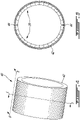
- FIG. 4 is a perspective schematic view of an exemplary duct 40 that may include one or more panels 20.
- Duct 40 may be part of inlet 22 of engine 10, or may form part of bypass duct 24 of engine 10 for example.
- Duct 40 may include (e.g., annular) base 42 to which panel(s) 20 may be mounted.
- Base 42 may be made from a suitable polymeric material, fiber-reinforced composite material (e.g., carbon fibers embedded in a polymeric resin) or metallic (e.g., aluminum-based) material.
- FIG. 5 is a schematic cross-section view of duct 40 taken along line 5-5 in FIG. 4 .
- One or more panel(s) 20 may be mounted to a radially-inner side and/or to a radially-outer side of base 42.
- a single panel 20 may be mounted to base 42 and cover part or substantially an entirety of the circumferential span of base 42.
- a plurality of panels 20 may be mounted to base 42 in a circumferentially adjacent manner to cover part or substantially an entirety of the circumferential span of base 42.
- two adjacent semicircular panels 20 are shown mounted to a radially-inner side of base 42.
- Intermediate parting lines 44 are shown schematically between the adjacent panels 20.
- a plurality of panels 20 may be mounted to any suitable base 42 to cooperatively provide an acoustically treated area of a desired shape and size.
- FIG. 6 is a schematic cross-section view of duct 40 of FIG. 4 taken along line 6-6 in FIG. 4 .
- Panel 20 may be formed to fit a profile defined in base 42 of duct 40 and may be inserted in base 42 as shown in FIG. 6 .
- Cellular structure 30 may have periphery P shown in FIG. 6 and representing an external boundary of cellular structure 30 within a plane intersecting and substantially parallel to panel 20. In other words, periphery P may be an outer edge of an acoustically treated area of panel 20.
- Backing member 26 may have a cross-sectional profile that substantially conforms to the cross-sectional profile of base 42.
- backing member 26 may have a "top hat" shaped cross-sectional profile including main portion 26A disposed inside periphery P of cellular structure 30 and peripheral portions 26B disposed outside of periphery P of cellular structure 30. In other words, backing member 26 may extend outwardly beyond periphery P of cellular structure 30.
- Backing member 26 may also include transitions portions 26C that interconnect respective peripheral portions 26B to main portion 26A. Transition portions 26C may provide step-shaped transitions between main portion 26A and respective peripheral portions 26B.
- transition portion 26C may eliminate the need for a ramped or "pan down" region of panel 20 that would take away from the acoustically treated area of panel 20. Accordingly, the step-shaped transitions provided by transition portions 26C may facilitate a larger acoustically treated area in the space available for panel 20 compared to ramped transitions for example.
- transition portions 26C may be substantially perpendicular to main portion 26A. However, in some embodiments, transition portions 26C may instead be non-perpendicular to main portion and provide ramp-shaped transitions interconnecting main portion 26A with respective peripheral portions 26B.
- Facing sheet 28 may include main portion 28A disposed inside periphery P of cellular structure 30 and peripheral portions 28B disposed outside of periphery P of cellular structure 30. In other words, facing sheet 28 may extend outwardly beyond periphery P of cellular structure 30. Peripheral portions 28B of facing sheet 28 may face respective corresponding peripheral portions 26B of backing member 26. Peripheral portions 28B of facing sheet 28 may be adjacent and (e.g., ultrasonically) welded to respective corresponding peripheral portions 26B of backing member 26.
- Components of panel 20 may be welded together or to base 42 at weld junctions 46. Additional or fewer weld junctions 46 than those shown in FIG 6 may be used.
- main portion 26A of backing member 26 may be welded to base 42.
- Peripheral portions 26B of backing member 26 may be welded to base 42.
- Peripheral portions 26B of backing member 26 and peripheral portions 28B of facing sheet 28 may be welded together to form a lap joint.
- Main portion 28A of facing sheet 28 and cellular structure 30 may be welded together.
- FIG. 7 is a flowchart illustrating an exemplary method 100 of manufacturing a sandwich-structured component such as panel 20. Aspects of method 100 may be combined with method steps or other aspects described herein. Aspects of method 100 are illustrated in FIGS. 8A-9B .
- Method 100 may include: receiving backing member 26, facing sheet 28 (or septum 34), and cellular structure 30 (block 102); assembling cellular structure 30 between backing member 26 and facing sheet 28 (or septum 34) (block 104); and ultrasonically welding backing member 26 and facing sheet 28 (or septum 34) together (block 106).
- Weld junctions 46 may be produced by ultrasonic welding as explained further below. Alternatively, weld junctions 46 may be made using other suitable low-temperature methods of welding such as seam welding or linear friction welding. Weld junctions 46 may include a union or fusion of components made after rendering part of the components to be joined soft or pasty using heat, and with or without the use of fusible filler material.
- FIG. 8A schematically illustrates backing member 26 of panel 20 formed from (e.g., flat) precursor sheet 48 prior to assembly with base 42.
- Backing member 26 may be formed to the desired shape using any suitable metal or polymer forming techniques. In some embodiments where backing member 26 is made from a metallic material, backing member 26 may formed from precursor sheet 48 by stamping or conventional welding for example. In some embodiments where backing member 26 is made from a polymer, backing member 26 may be thermoformed from precursor sheet 48 or injection molded for example. In some embodiments, backing member 26 may define recess 50 in which cellular structure 30 may be inserted. Peripheral portions 26B may be disposed outside a periphery of recess 50.
- FIG. 8B schematically illustrates assembling backing member 26 with base 42 and ultrasonically welding backing member 26 to base 42 using sonotrode 52.
- base 42 may be held on a suitable anvil to facilitate the ultrasonic welding process.
- a suitable anvil or other suitable work holding equipment may be used to hold backing member 26 during assembly of panel 20 and during ultrasonic welding.
- optional metallic foil 54 may be laid between the components to be joined to facilitate ultrasonic welding.
- foil 54 may be a relatively thin piece made from a compatible polymeric material and laid between the components to be joined to facilitate ultrasonic welding.
- ultrasonic welding may provide flexibility in joining various materials via relatively strong structural bonds compared to some adhesive bonding approaches.
- the relatively high bond strength may facilitate bonding areas of reduced size for weld junctions 46 compared to the use of fasteners such as rivets or bolts.
- the use of ultrasonic welding may promote an increase in acoustically treated area in a given space, a reduction or elimination of blockage of through holes 36, 38 by adhesive material and/or potentially a weight reduction compared to existing acoustic panels made using other methods.
- the ultrasonic welding used herein may be a solid state welding process where no external heat is added for welding.
- Ultrasonic welding may be performed using sonotrode 52.
- Sonotrode 52 may be moved to locations to be welded and placed in contact with the workpieces to transmit energy to the workpieces by way of ultrasonic vibration.
- the ultrasonic vibration may create a dynamic shear stress between the contact surfaces of the workpieces. Due to local plastic deformation and heat generation due to friction between the contact surfaces, joint formation may take place at the interface between the two workpieces.
- Sonotrode 52 may be associated with a (e.g., piezoelectric) transducer which can convert high frequency electric signal into high frequency mechanical vibration.
- Oscillating shear forces acting at the interface between the workpieces may cause elastoplastic deformation at the interface.
- the local temperature may rise at the interface without significantly melting the workpieces and/or filler material.
- the welding may be achieved by disrupting the surface oxide films of the metallic components. Ultrasonic welding may be considered a relatively low heat procedure and may be used to weld metallic materials together, and polymeric materials together.
- FIG. 8C schematically illustrates assembling cellular structure 30 and facing sheet 28 with backing member 26 after backing member 26 has been installed with (and optionally welded to) base 42.
- Recess 50 (show in FIG. 8B ) may be at least partially filled with cellular structure 30 and covered with facing sheet 28.
- foil 54 may be disposed between main portion 28A of facing sheet 28 and cellular structure 30 to facilitate ultrasonic welding therebetween.
- foil 54 may be disposed between peripheral portion 28B of facing sheet 28 and peripheral portion 26B of backing member 26 to facilitate ultrasonic welding therebetween.
- FIG. 8D schematically illustrates ultrasonically welding peripheral portion 28B of facing sheet 28 to peripheral portion 26B of backing member 26 to form weld junction 46 using sonotrode 52.
- main portion 28A of facing sheet 28 may be ultrasonically welded to cellular portion 30 using sonotrode 52 also.
- base 42 may function as a suitable backing member and a separate intermediate backing member 26 overlaying base 42 may not be required.
- cellular structure 30 may be inserted into a recess formed in base 42 and peripheral portion 28B of facing sheet 28 may be ultrasonically welded directly to a peripheral portion of base 42 so that base 42 may serve as a backing member of panel 20.
- ultrasonic welding may also be used at the ply lay-up stage to bond plies (e.g., pre-impregnated fabric or unidirectional tape) together and the resulting lay-up may be subsequently consolidated in an autoclave.
- plies e.g., pre-impregnated fabric or unidirectional tape
- UAM layer-by-layer ultrasonic additive manufacturing
- FIG. 9A schematically illustrates an exploded view of DDOF acoustic panel 20B to be assembled with base 42.
- Method 100 and other aspects described above in relation to manufacturing SDOF acoustic panel 20A may be used to make DDOF acoustic panel 20B.
- backing member 26 may be installed with base 42 and optionally ultrasonically welded to base 42 as described above.
- Cellular structure 30A may be assembled to be disposed between backing member 26 and septum 34 which may be perforated with through holes 38. Cellular structure 30A may be inserted into recess 50 defined by backing member 26.
- Septum 34 may have first peripheral portions 34B disposed outside periphery P1 of cellular structure 30A. First peripheral portions 34B of septum 34 may be facing and disposed adjacent to respective peripheral portions 26B of backing member 26 to provide a lap joint to permit ultrasonic welding.
- Septum 34 may also be formed to have a "top hat" shape similar to backing member 26.
- Cellular structure 30B may be installed between septum 34 and facing sheet 28.
- Septum 34 may define recess 56 in which cellular structure 30B may be inserted.
- Septum 34 may also have second peripheral portions 34D that are disposed outside a periphery P2 of cellular structure 30B. Second peripheral portions 34D of septum 34 may facilitate ultrasonic welding of septum 34 to base 42.
- Transition portions 34C may interconnect second peripheral portions 34D to respective first peripheral portions 34B of septum 34. Each transition portion 34C may define a step-shaped transition or a ramp-shaped transition.
- transition portions 34C may be substantially perpendicular to main portion 34A of septum 34 disposed within periphery P1 of cellular structure 30A.
- Peripheral portions 28B of facing sheet 28 may be disposed outside periphery P2 of facing sheet 28.
- Peripheral portions 28B of facing sheet 28 and corresponding second peripheral portions 34D of septum 34 may face each other and be disposed adjacent each other to define a lap joint to facilitate ultrasonic welding.
- the assembly order of the parts of SDOF acoustic panel 20A or of DDOF acoustic panel 20B may be varied from those depicted herein.
- the entire SDOF acoustic panel 20A or DDOF acoustic panel 20B may be assembled separately from base 42 and subsequently assembled (e.g., adhesively bonded, welded, fastened) with base 42.
- One or more optional foils 54 as shown in FIG. 8C may also be used to facilitate ultrasonic welding of components of DDOF acoustic panel 20B.
- FIG. 9B schematically illustrates ultrasonically welding components of DDOF acoustic panel 20B using sonotrode 52.
- DDOF acoustic panel 20B may contain a plurality of weld junctions 46 throughout DDOF acoustic panel 20B and acoustic welding operations may be carried out between assembly steps to provide sonotrode 52 access to the components to be welded.
- One or more weld junctions 46 may be produced between main portion 26A of backing member 26 and base 42.
- One or more weld junctions 46 may be produced between peripheral portion(s) 26B of backing member 26 and base 42.
- One or more weld junctions 46 may be produced between main portion 34A of septum 34 and cellular structure 30A.
- One or more weld junctions 46 may be produced between first peripheral portion(s) 34B of septum 34 and respective peripheral portion(s) 26B of backing member 26. One or more weld junctions 46 may be produced between second peripheral portion(s) 34D of septum 34 and base 42. One or more weld junctions 46 may be produced between peripheral portion(s) 28B of facing sheet 28 and respective second peripheral portion(s) 34D of septum 34. One or more weld junctions 46 may be produced between main portion 28A of facing sheet 28 and cellular structure 30B.
- base 42 may function as a suitable backing member and a separate intermediate backing member 26 overlaying base 42 may not be required in the construction of DDOF acoustic panel 20B either.
- cellular structure 30A may be inserted into a recess formed in base 42 and first peripheral portion 34B of septum 34 may be ultrasonically welded directly to 42 so that base 42 may serve as a backing member of DDOF acoustic panel 20.
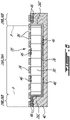
- FIG. 10 is a schematic representation of part of another exemplary sandwich-structured panel 120 which may be suitable for structural applications.
- first skin 126 and second skin 128 are not perforated.
- Panel 120 may include elements previously described above and reference numerals for like elements have been incremented by 100.
- Ultrasonic welding may be used to produce weld junctions 146.
- One or more weld junctions 146 may be produced between main portion 126A of first skin 126 and cellular structure 130.
- One or more weld junctions 146 may be produced between main portion 128A of second skin 128 and cellular structure 130.
- One or more weld junctions 146 may be produced between peripheral portion 126B of first skin 126 and peripheral portion 128B of second skin 128.
- Transition portion 126C of first skin 126 may define a step-shaped transition between peripheral portion 126B of first skin 126 and main portion 126A of first skin 126 disposed inside the periphery of cellular structure 130.
- Transition portion 128C of second skin 128 may define a step-shaped transition between peripheral portion 128B of second skin 128 and main portion 128A of second skin 128 disposed inside the periphery of cellular structure 130.
- ultrasonic welding may also facilitate the fabrication of other components such as bracket 58, flanges and/or other accessories integrated to panels, ducts and bases described herein through the use of UAM to reduce or eliminate the use of fasteners.
- UAM may include stacking and fusing (e.g., welding) metallic or polymeric strips 60 in a layer-by-layer manner using ultrasonic welding to build-up such components.
- the panels described herein may be used in components such as ducts, aircraft stringers and aircraft fuselage skins for example. The panels described herein may be used for shock-absorbing and/or insulating functions.
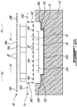
- FIG. 11 is a schematic representation of part of another exemplary sandwich-structured panel 220 which may be suitable for structural applications.
- first skin 226 and second skin 228 may not be perforated.
- Panel 220 may include elements previously described above and reference numerals for like elements have been incremented by 200.
- Ultrasonic welding may be used to produce weld junctions 246.
- One or more weld junctions 246 may be produced between main portion 226A of first skin 226 and cellular structure 230.
- One or more weld junctions 246 may be produced between main portion 228A of second skin 228 and cellular structure 230.
- One or more weld junctions 246 may be produced between peripheral portion 226B of first skin 226 and peripheral portion 228B of second skin 228.
- Transition portion 226C of first skin 226 may define a ramp-shaped transition between peripheral portion 226B of first skin 226 and main portion 226A of first skin 226 disposed inside the periphery of cellular structure 230.
Landscapes
- Engineering & Computer Science (AREA)
- Mechanical Engineering (AREA)
- General Engineering & Computer Science (AREA)
- Physics & Mathematics (AREA)
- Acoustics & Sound (AREA)
- Multimedia (AREA)
- Architecture (AREA)
- Civil Engineering (AREA)
- Structural Engineering (AREA)
- Lining Or Joining Of Plastics Or The Like (AREA)
- Laminated Bodies (AREA)
- Soundproofing, Sound Blocking, And Sound Damping (AREA)
Abstract
Description
- The invention relates generally to aircraft components, and more particularly to sandwich-structured panels.
- A gas turbine engine powering an aircraft in flight produces noise and acoustic treatment in the engine can be used to attenuate some of the noise. A single-degree of freedom (SDOF) acoustic panel construction can include a honeycomb core disposed between a backing sheet and a porous (e.g., perforated) facing sheet. The space between the backing sheet and the facing sheet defines a noise-attenuating cavity. A double-degree of freedom (DDOF) acoustic panel construction can include two honeycomb cores joined together at an intermediate porous septum. The arrangement of the two honeycomb cores and the septum are disposed between a backing sheet and a porous (e.g., perforated) facing sheet to define two noise-attenuating cavities.
- Components of such acoustic treatment are typically assembled and joined together using an adhesive reticulation process where a film-adhesive is used to join the edges of the honeycomb cells to the facing sheet and backing sheet. During the joining process, some excess adhesive material can flow into and block holes formed into the facing sheet of the acoustic panel. The blocking of the holes by the adhesive material can reduce the noise attenuation efficiency of the acoustic panel. Existing approaches for securing components of the panels together can also take away space that could otherwise be used as acoustically treated areas of the panels. Improvement is desirable.
- In one aspect, the disclosure describes a method of manufacturing a sandwich-structured panel. The method comprises: receiving a first skin, a second skin and a cellular core; assembling the cellular core with the first and second skins so that: the cellular core is disposed between the first and second skins; the first skin has a peripheral portion disposed outside a periphery of the cellular core; the second skin has a peripheral portion disposed outside the periphery of the cellular core and facing the peripheral portion of the first skin, the peripheral portion of the second skin being adjacent the peripheral portion of the first skin; and ultrasonically welding the peripheral portion of the first skin and the peripheral portion of the second skin together.
- In another aspect, the disclosure describes a method of manufacturing an aircraft component. The method comprises: receiving a backing member, a sheet and a cellular structure; assembling the cellular structure between the backing member and the sheet; and ultrasonically welding the backing member and the sheet together.
- In a further aspect, the disclosure describes a sandwich-structured panel comprising: a first skin; a second skin disposed relative to the first skin to define a cavity between the first and second skins; and a cellular core disposed in the cavity between the first and second skins; wherein: the first skin has a peripheral portion disposed outside a periphery of the cellular core; the second skin has a peripheral portion disposed outside the periphery of the cellular core and facing the peripheral portion of the first skin, the peripheral portion of the second skin being adjacent the peripheral portion of the first skin; and the peripheral portion of the first skin and the peripheral portion of the second skin are welded together.
- Features of embodiments are recited the dependent claims.
- Further details of these and other aspects of the subject matter of this application will be apparent from the detailed description included below and the drawings.
- Reference is now made to the accompanying drawings, in which:
-
FIG. 1 shows an axial schematic cross-section view of an exemplary turbofan gas turbine engine including one or more sandwich-structured panels as described herein; -
FIG. 2 is a perspective cutaway view of an exemplary sandwich-structured panel in the form of a single-degree-of-freedom (SDOF) acoustic panel; -
FIG. 3 is a perspective cutaway view of another exemplary sandwich-structured panel in the form of a double-degree-of-freedom (DDOF) acoustic panel; -
FIG. 4 is a perspective schematic view of an exemplary duct including a sandwich-structured panel as described herein; -
FIG. 5 is a schematic cross-section view of the duct ofFIG. 4 taken along line 5-5 inFIG. 4 ; -
FIG. 6 is a schematic cross-section view of the duct ofFIG. 4 taken along line 6-6 inFIG. 4 ; -
FIG. 7 is a flowchart illustrating an exemplary method of manufacturing an aircraft component in the form of a sandwich-structured panel; -
FIG. 8A schematically illustrates a backing member of a sandwich-structured panel formed from a precursor sheet; -
FIG. 8B schematically illustrates assembling the backing member ofFIG. 8A with a base and ultrasonically welding the backing member to the base; -
FIG. 8C schematically illustrates assembling a cellular structure and a facing sheet with the backing member ofFIG. 8A ; -
FIG. 8D schematically illustrates ultrasonically welding the facing sheet ofFIG. 8C to the backing member ofFIG. 8A and to the cellular structure; -
FIG. 9A schematically illustrates an exploded view of a sandwich-structured panel in the form of a DDOF acoustic panel; -
FIG. 9B schematically illustrates ultrasonically welding components of the sandwich-structured panel ofFIG. 9A ; -
FIG. 10 is a schematic representation of part of another exemplary sandwich-structured panel; and -
FIG. 11 is a schematic representation of part of another exemplary sandwich-structured panel. - Sandwich-structured components (e.g., panels) of aircraft and methods for manufacturing such components are described herein. The components may be suitable for use in various structural and/or noise-attenuating applications including on structures (i.e., airframes) of aircraft or other mobile platforms, in aircraft engines, in automotive applications, buildings and/or in other structural applications for example. In various embodiments, the components described herein may include or be part of walls, panels, liners or ducts for example. In some embodiments, the components may serve as acoustic treatment and may be referred to as "acoustic panels" or "acoustic liners" with desirable noise-attenuating properties. Such components may be installed to line a duct (e.g., inlet or bypass duct) of a gas turbine engine or may be installed in any other location(s) such as inside a passenger cabin of an aircraft or on the exterior of an aircraft where noise attenuation is desirable. While the following description refers to acoustic treatment (e.g., panels) for aircraft applications, it is understood that sandwich-structured components and methods described herein may be suitable for use in other applications.
- In some embodiments, the components and methods described herein make use of ultrasonic welding for joining parts of the components together so that the need for adhesive material (e.g., glue) used in conventional assembly methods such as adhesive reticulation can be reduced or eliminated. In the case of acoustic panels, the reduction or elimination of adhesive material can reduce or eliminate the risk of excess adhesive material flowing into and blocking holes formed into the facing sheet and/or the septum of such acoustic panels. In some embodiments, the use of ultrasonic welding may simplify the construction of sandwich-structured panels. In some embodiments, the ultrasonically-welded joints between parts of acoustic panels may make efficient use of space to leave more space available for acoustically treated areas of acoustic panels.
- Terms such as "attached", "connected" and "coupled" may include both direct attachment, connection or coupling (in which two elements contact each other) and indirect attachment, connection or coupling (in which at least one additional element is located between the two elements). The term "substantially" as used herein may be applied to modify any quantitative representation which could permissibly vary without resulting in a change in the basic function to which it is related. Aspects of various embodiments are described through reference to the drawings.
-
FIG. 1 illustratesgas turbine engine 10 of a type preferably provided for use on an aircraft, generally comprising in serial flow communication,fan 12 through which ambient air is propelled,multistage compressor 14 for pressurizing the air,combustor 16 in which the compressed air is mixed with fuel and ignited for generating an annular stream of hot combustion gases, andturbine section 18 for extracting energy from the combustion gases. -
Engine 10 may include one or more sandwich-structuredpanels 20, 20A, 20B (referred generically herein as "panel 20") used as acoustic treatment (e.g., panels or liners) disposed at different locations withinengine 10 to obtain desired noise-attenuation. It is understood thatpanel 20 may be used in other types of engines (e.g., turboshaft, turboprop, auxiliary power unit (APU)) and in other types of noise-attenuating applications. In some embodiments,panel 20 may be used in structural applications that are not necessarily intended to provide noise-attenuation. - In some situations, panel(s) 20 (e.g., acoustic liner) may be disposed upstream and/or downstream of
fan 12 inside ofengine 10 so that noise produced byfan 12 may be attenuated. For example, panel(s) 20 may be integrated ininlet 22 ofengine 10 and disposed upstream offan 12. Alternatively or in addition, panel(s) 20 may be integrated in (e.g., annular)bypass duct 24 and define a radially-outer and/or a radially-inner surface ofbypass duct 24. In various embodiments,panel 20 may be suitable for use in a fan case, intermediate case, bypassduct 24, exhaust duct, thrust reverser duct, and an exhaust center body ofengine 10 for example. In some embodiments,panel 20 may be suitable for use in a hot core section duct ofengine 10 where adhesively bonded acoustic materials would typically not be used due to elevated temperatures. Depending on the specific application,panel 20 may have a generally planar or non-planar (e.g., curved, arcuate, annular) form (e.g., of single or double curvature). -
FIG. 2 is a perspective cutaway view of an exemplary sandwich-structured panel 20A in the form of a single-degree-of-freedom (SDOF) acoustic panel. SDOF acoustic panel 20A may include backingmember 26, facingsheet 28 andcellular structure 30 disposed betweenbacking member 26 and facingsheet 28. Facingsheet 28 may be spaced apart from backingmember 26 to define (e.g., noise-attenuating)cavity 32 betweenbacking member 26 and facingsheet 28. - As explained below,
cellular structure 30 may be attached to backingmember 26 and/or facingsheet 28 through ultrasonic welding.Cellular structure 30 may include walls serving as partitions defining sub-cavities (cells) within noise-attenuatingcavity 32.Cellular structure 30 may serve as a core of SDOF acoustic panel 20A. In some embodiments, backingmember 26 may have the form of a sheet or plate. However, it is understood that backingmember 26 may be of any suitable shape and thickness. For example, backingmember 26 may be a part of another component ofengine 10 such as a wall ofinlet 22 orbypass duct 24 ofengine 10 that provides a suitable back wall for noise-attenuatingcavity 32. Backingmember 26 and facingsheet 28 may serve as skins of SDOF acoustic panel 20A disposed on opposite sides ofcellular structure 30. -
FIG. 3 is a perspective cutaway view of an exemplary sandwich-structured composite panel 20B in the form of a double-degree-of-freedom (DDOF) acoustic panel. DDOF acoustic panel 20B may include backingmember 26,septum 34,cellular structures sheet 28.Septum 34 may be spaced apart from backingmember 26 to define (e.g., noise-attenuating)cavity 32A betweenbacking member 26 andseptum 34.Cellular structure 30A may be disposed betweenbacking member 26 andseptum 34. As explained below,cellular structure 30A may be attached to backingmember 26 and/orseptum 34 through ultrasonic welding. - Facing
sheet 28 may be spaced apart fromseptum 34 to define (e.g., noise-attenuating)cavity 32B betweenseptum 34 and facingsheet 28.Cellular structure 30B may be disposed between facingsheet 28 andseptum 34. Similarly,cellular structure 30B may be attached to facingsheet 28 and/orseptum 34 through ultrasonic welding. Due to its configuration, DDOF acoustic panel 20B may, in some embodiments, resonate and attenuate noise at multiple frequencies or within a wider frequency range than SDOF acoustic panel 20A. - In reference to the SDOF and DDOF acoustic panels 20A, 20B of
FIGS. 2 and 3 respectively,cellular structures cellular structure 30") may each include a plurality of open-ended juxtaposed cells of hexagonal or other (e.g., triangular, rectangular, polygonal) cross-sectional profile. For example, in the case of SDOF acoustic panel 20A, the walls defining the cells ofcellular structure 30 may extend from backingmember 26 to facingsheet 28 and may provide structural support between facingsheet 28 andbacking member 26. In the case of DDOF acoustic panel 20B, the walls defining the cells ofcellular structure 30B may extend fromseptum 34 to facingsheet 28, and the walls defining the cells ofcellular structure 30A may extend from backingmember 26 toseptum 34. - In some embodiments,
cellular structure 30 may be of a type referred to as "honeycomb" core.Cellular structure 30 may be made from a suitable non-metallic material (e.g., polymer), fiber-reinforced composite material (e.g., carbon fibre/resin matrix) or metallic (e.g., aluminum-based) material for example. - In noise-attenuating applications, outer facing
sheet 28 may be porous (e.g., perforated) and may include a plurality of throughholes 36 formed (e.g., drilled) therein. In some embodiments, holes 36 may have a substantially circular cross-sectional shape but other cross-sectional shapes such as ovals or rectangles may also be suitable. For example, holes 36 may include one or more slits. In some embodiments, one ormore holes 36 may be in communication with each cell defined bycellular structure 30 and each cell may function as a resonator. In some embodiments, a highly resistive material such as a mesh of porous material may be disposed inside or outside the cells defined by cellular structure 30 (e.g., bonded above or below facing sheet 28) and may alter the noise-attenuating performance of SDOF acoustic panel 20A. Facingsheet 28 may be made from a suitable metallic, plastic or composite material. For example, facingsheet 28 may be made from fiber-reinforced composite material (e.g., carbon fibers embedded in a polymeric resin) or metallic (e.g., aluminum-based or metal) material. In some embodiments, facingsheet 28 may have a thickness permitting ultrasonically welding facingsheet 28 to another component. In various embodiments, facingsheet 28 may have a thickness of between 1 mm and 6.5 mm for example. However, other thicknesses may be suitable for various applications. - Backing
member 26 may be unperforated and include a non-porous impermeable sheet, plate or other relatively hard material. Backingmember 26 may be made from a suitable metallic, plastic or composite material. For example, backingmember 26 may be made from fiber-reinforced composite material (e.g., carbon fibers embedded in a polymeric resin) or metallic (e.g., aluminum-based or metal) material. In some embodiments, backingmember 26 may have a thickness permitting ultrasonically welding backingmember 26 to another component. - In noise-attenuating applications,
septum 34 may be a porous (e.g., perforated) sheet or plate and may include a plurality of throughholes 38 formed (e.g., drilled) therein for acoustically connecting noise-attenuatingcavities Septum 34 may serve as an intermediate (e.g., perforated) skin disposed betweencellular structure 30A andcellular structure 30B.Septum 34 may be made from a suitable metallic, plastic or composite material. For example,septum 34 may be made from fiber-reinforced composite material (e.g., carbon fibers embedded in a polymeric resin), metallic (e.g., aluminum-based or metal) material, or fibrous material such as fiber cloth and mesh cloth. In some embodiments,septum 34 may include a perforated sheet of similar of substantially the same construction as facingsheet 28. In some embodiments,septum 34 may have a thickness permitting ultrasonically weldingseptum 34 to another component. In various embodiments,septum 34 may have a thickness of between 0.3 mm and 2.5 mm for example. However, other thicknesses may be suitable for various applications. -
Cellular structure 30 may serve as a relatively low-density core disposed between two relatively stronger skins such asbacking member 26, facingsheet 28 and/orseptum 34. In the context of structural applications, the resulting sandwich-structuredpanel 20 may provide a combination of relatively high structural rigidity and low weight, as the skins provide resistance to in-plane and lateral bending loads, while the core provides resistance to shear loads. In non-noise-attenuating applications, facingsheet 28 and/orseptum 34 may not be perforated (i.e., devoid of throughholes 36, 38). Materials of components ofpanel 20 may be selected to be compatible for ultrasonic welding together. -
FIG. 4 is a perspective schematic view of anexemplary duct 40 that may include one ormore panels 20.Duct 40 may be part ofinlet 22 ofengine 10, or may form part ofbypass duct 24 ofengine 10 for example.Duct 40 may include (e.g., annular)base 42 to which panel(s) 20 may be mounted.Base 42 may be made from a suitable polymeric material, fiber-reinforced composite material (e.g., carbon fibers embedded in a polymeric resin) or metallic (e.g., aluminum-based) material. -
FIG. 5 is a schematic cross-section view ofduct 40 taken along line 5-5 inFIG. 4 . One or more panel(s) 20 may be mounted to a radially-inner side and/or to a radially-outer side ofbase 42. In some embodiments, asingle panel 20 may be mounted tobase 42 and cover part or substantially an entirety of the circumferential span ofbase 42. In some embodiments, a plurality ofpanels 20 may be mounted tobase 42 in a circumferentially adjacent manner to cover part or substantially an entirety of the circumferential span ofbase 42. In the example shown inFIG. 5 , two adjacentsemicircular panels 20 are shown mounted to a radially-inner side ofbase 42.Intermediate parting lines 44 are shown schematically between theadjacent panels 20. A plurality ofpanels 20 may be mounted to anysuitable base 42 to cooperatively provide an acoustically treated area of a desired shape and size. -
FIG. 6 is a schematic cross-section view ofduct 40 ofFIG. 4 taken along line 6-6 inFIG. 4 .Panel 20 may be formed to fit a profile defined inbase 42 ofduct 40 and may be inserted inbase 42 as shown inFIG. 6 .Cellular structure 30 may have periphery P shown inFIG. 6 and representing an external boundary ofcellular structure 30 within a plane intersecting and substantially parallel topanel 20. In other words, periphery P may be an outer edge of an acoustically treated area ofpanel 20. - Backing
member 26 may have a cross-sectional profile that substantially conforms to the cross-sectional profile ofbase 42. For example, backingmember 26 may have a "top hat" shaped cross-sectional profile includingmain portion 26A disposed inside periphery P ofcellular structure 30 andperipheral portions 26B disposed outside of periphery P ofcellular structure 30. In other words, backingmember 26 may extend outwardly beyond periphery P ofcellular structure 30. Backingmember 26 may also includetransitions portions 26C that interconnect respectiveperipheral portions 26B tomain portion 26A.Transition portions 26C may provide step-shaped transitions betweenmain portion 26A and respectiveperipheral portions 26B. The step-shaped transition provided bytransition portion 26C may eliminate the need for a ramped or "pan down" region ofpanel 20 that would take away from the acoustically treated area ofpanel 20. Accordingly, the step-shaped transitions provided bytransition portions 26C may facilitate a larger acoustically treated area in the space available forpanel 20 compared to ramped transitions for example. In some embodiments,transition portions 26C may be substantially perpendicular tomain portion 26A. However, in some embodiments,transition portions 26C may instead be non-perpendicular to main portion and provide ramp-shaped transitions interconnectingmain portion 26A with respectiveperipheral portions 26B. - Facing
sheet 28 may includemain portion 28A disposed inside periphery P ofcellular structure 30 andperipheral portions 28B disposed outside of periphery P ofcellular structure 30. In other words, facingsheet 28 may extend outwardly beyond periphery P ofcellular structure 30.Peripheral portions 28B of facingsheet 28 may face respective correspondingperipheral portions 26B of backingmember 26.Peripheral portions 28B of facingsheet 28 may be adjacent and (e.g., ultrasonically) welded to respective correspondingperipheral portions 26B of backingmember 26. - Components of
panel 20 may be welded together or to base 42 atweld junctions 46. Additional orfewer weld junctions 46 than those shown inFIG 6 may be used. For example,main portion 26A of backingmember 26 may be welded tobase 42.Peripheral portions 26B of backingmember 26 may be welded tobase 42.Peripheral portions 26B of backingmember 26 andperipheral portions 28B of facingsheet 28 may be welded together to form a lap joint.Main portion 28A of facingsheet 28 andcellular structure 30 may be welded together. -
FIG. 7 is a flowchart illustrating anexemplary method 100 of manufacturing a sandwich-structured component such aspanel 20. Aspects ofmethod 100 may be combined with method steps or other aspects described herein. Aspects ofmethod 100 are illustrated inFIGS. 8A-9B .Method 100 may include: receiving backingmember 26, facing sheet 28 (or septum 34), and cellular structure 30 (block 102); assemblingcellular structure 30 betweenbacking member 26 and facing sheet 28 (or septum 34) (block 104); and ultrasonically welding backingmember 26 and facing sheet 28 (or septum 34) together (block 106). - Weld junctions 46 (shown in
FIG. 6 ) may be produced by ultrasonic welding as explained further below. Alternatively,weld junctions 46 may be made using other suitable low-temperature methods of welding such as seam welding or linear friction welding.Weld junctions 46 may include a union or fusion of components made after rendering part of the components to be joined soft or pasty using heat, and with or without the use of fusible filler material. -
FIG. 8A schematically illustrates backingmember 26 ofpanel 20 formed from (e.g., flat)precursor sheet 48 prior to assembly withbase 42. Backingmember 26 may be formed to the desired shape using any suitable metal or polymer forming techniques. In some embodiments where backingmember 26 is made from a metallic material, backingmember 26 may formed fromprecursor sheet 48 by stamping or conventional welding for example. In some embodiments where backingmember 26 is made from a polymer, backingmember 26 may be thermoformed fromprecursor sheet 48 or injection molded for example. In some embodiments, backingmember 26 may definerecess 50 in whichcellular structure 30 may be inserted.Peripheral portions 26B may be disposed outside a periphery ofrecess 50. -
FIG. 8B schematically illustrates assemblingbacking member 26 withbase 42 and ultrasonically welding backingmember 26 tobase 42 usingsonotrode 52. In embodiments wherepanel 20 is integrated withbase 42,base 42 may be held on a suitable anvil to facilitate the ultrasonic welding process. In embodiments wherepanel 20 is not integrated with and welded tobase 42, a suitable anvil or other suitable work holding equipment may be used to hold backingmember 26 during assembly ofpanel 20 and during ultrasonic welding. In some embodiments, optionalmetallic foil 54 may be laid between the components to be joined to facilitate ultrasonic welding. In some embodiments where polymeric components ofpanel 20 are ultrasonically welded together, foil 54 may be a relatively thin piece made from a compatible polymeric material and laid between the components to be joined to facilitate ultrasonic welding. - The use of ultrasonic welding may provide flexibility in joining various materials via relatively strong structural bonds compared to some adhesive bonding approaches. In some embodiments, the relatively high bond strength may facilitate bonding areas of reduced size for
weld junctions 46 compared to the use of fasteners such as rivets or bolts. Accordingly, the use of ultrasonic welding may promote an increase in acoustically treated area in a given space, a reduction or elimination of blockage of throughholes - The ultrasonic welding used herein may be a solid state welding process where no external heat is added for welding. Ultrasonic welding may be performed using
sonotrode 52.Sonotrode 52 may be moved to locations to be welded and placed in contact with the workpieces to transmit energy to the workpieces by way of ultrasonic vibration. The ultrasonic vibration may create a dynamic shear stress between the contact surfaces of the workpieces. Due to local plastic deformation and heat generation due to friction between the contact surfaces, joint formation may take place at the interface between the two workpieces.Sonotrode 52 may be associated with a (e.g., piezoelectric) transducer which can convert high frequency electric signal into high frequency mechanical vibration. Oscillating shear forces acting at the interface between the workpieces may cause elastoplastic deformation at the interface. The local temperature may rise at the interface without significantly melting the workpieces and/or filler material. When joining metallic components, the welding may be achieved by disrupting the surface oxide films of the metallic components. Ultrasonic welding may be considered a relatively low heat procedure and may be used to weld metallic materials together, and polymeric materials together. -
FIG. 8C schematically illustrates assemblingcellular structure 30 and facingsheet 28 with backingmember 26 after backingmember 26 has been installed with (and optionally welded to)base 42. Recess 50 (show inFIG. 8B ) may be at least partially filled withcellular structure 30 and covered with facingsheet 28. In some embodiments, foil 54 may be disposed betweenmain portion 28A of facingsheet 28 andcellular structure 30 to facilitate ultrasonic welding therebetween. In some embodiment, foil 54 may be disposed betweenperipheral portion 28B of facingsheet 28 andperipheral portion 26B of backingmember 26 to facilitate ultrasonic welding therebetween. -
FIG. 8D schematically illustrates ultrasonically weldingperipheral portion 28B of facingsheet 28 toperipheral portion 26B of backingmember 26 to formweld junction 46 usingsonotrode 52. In some embodiments,main portion 28A of facingsheet 28 may be ultrasonically welded tocellular portion 30 usingsonotrode 52 also. - In some embodiments,
base 42 may function as a suitable backing member and a separateintermediate backing member 26overlaying base 42 may not be required. For example,cellular structure 30 may be inserted into a recess formed inbase 42 andperipheral portion 28B of facingsheet 28 may be ultrasonically welded directly to a peripheral portion ofbase 42 so thatbase 42 may serve as a backing member ofpanel 20. - In situations where one or more components such as
backing member 26 or facingsheet 28 is made from fiber reinforced composite materials, ultrasonic welding may also be used at the ply lay-up stage to bond plies (e.g., pre-impregnated fabric or unidirectional tape) together and the resulting lay-up may be subsequently consolidated in an autoclave. In other words, a layer-by-layer ultrasonic additive manufacturing (UAM) process may be used to form one or more components ofpanel 20. -
FIG. 9A schematically illustrates an exploded view of DDOF acoustic panel 20B to be assembled withbase 42.Method 100 and other aspects described above in relation to manufacturing SDOF acoustic panel 20A may be used to make DDOF acoustic panel 20B. In some embodiments, backingmember 26 may be installed withbase 42 and optionally ultrasonically welded to base 42 as described above.Cellular structure 30A may be assembled to be disposed betweenbacking member 26 andseptum 34 which may be perforated with throughholes 38.Cellular structure 30A may be inserted intorecess 50 defined by backingmember 26.Septum 34 may have firstperipheral portions 34B disposed outside periphery P1 ofcellular structure 30A. Firstperipheral portions 34B ofseptum 34 may be facing and disposed adjacent to respectiveperipheral portions 26B of backingmember 26 to provide a lap joint to permit ultrasonic welding. -
Septum 34 may also be formed to have a "top hat" shape similar to backingmember 26.Cellular structure 30B may be installed betweenseptum 34 and facingsheet 28.Septum 34 may definerecess 56 in whichcellular structure 30B may be inserted.Septum 34 may also have secondperipheral portions 34D that are disposed outside a periphery P2 ofcellular structure 30B. Secondperipheral portions 34D ofseptum 34 may facilitate ultrasonic welding ofseptum 34 tobase 42.Transition portions 34C may interconnect secondperipheral portions 34D to respective firstperipheral portions 34B ofseptum 34. Eachtransition portion 34C may define a step-shaped transition or a ramp-shaped transition. In some embodiments,transition portions 34C may be substantially perpendicular tomain portion 34A ofseptum 34 disposed within periphery P1 ofcellular structure 30A.Peripheral portions 28B of facingsheet 28 may be disposed outside periphery P2 of facingsheet 28.Peripheral portions 28B of facingsheet 28 and corresponding secondperipheral portions 34D ofseptum 34 may face each other and be disposed adjacent each other to define a lap joint to facilitate ultrasonic welding. - In various embodiments, the assembly order of the parts of SDOF acoustic panel 20A or of DDOF acoustic panel 20B may be varied from those depicted herein. For example, the entire SDOF acoustic panel 20A or DDOF acoustic panel 20B may be assembled separately from
base 42 and subsequently assembled (e.g., adhesively bonded, welded, fastened) withbase 42. One or moreoptional foils 54 as shown inFIG. 8C may also be used to facilitate ultrasonic welding of components of DDOF acoustic panel 20B. -
FIG. 9B schematically illustrates ultrasonically welding components of DDOF acoustic panel20B using sonotrode 52. DDOF acoustic panel 20B may contain a plurality ofweld junctions 46 throughout DDOF acoustic panel 20B and acoustic welding operations may be carried out between assembly steps to providesonotrode 52 access to the components to be welded. One ormore weld junctions 46 may be produced betweenmain portion 26A of backingmember 26 andbase 42. One ormore weld junctions 46 may be produced between peripheral portion(s) 26B of backingmember 26 andbase 42. One ormore weld junctions 46 may be produced betweenmain portion 34A ofseptum 34 andcellular structure 30A. One ormore weld junctions 46 may be produced between first peripheral portion(s) 34B ofseptum 34 and respective peripheral portion(s) 26B of backingmember 26. One ormore weld junctions 46 may be produced between second peripheral portion(s) 34D ofseptum 34 andbase 42. One ormore weld junctions 46 may be produced between peripheral portion(s) 28B of facingsheet 28 and respective second peripheral portion(s) 34D ofseptum 34. One ormore weld junctions 46 may be produced betweenmain portion 28A of facingsheet 28 andcellular structure 30B. - In some embodiments,
base 42 may function as a suitable backing member and a separateintermediate backing member 26overlaying base 42 may not be required in the construction of DDOF acoustic panel 20B either. For example,cellular structure 30A may be inserted into a recess formed inbase 42 and firstperipheral portion 34B ofseptum 34 may be ultrasonically welded directly to 42 so thatbase 42 may serve as a backing member of DDOFacoustic panel 20. -
FIG. 10 is a schematic representation of part of another exemplary sandwich-structuredpanel 120 which may be suitable for structural applications. In some embodiments,first skin 126 andsecond skin 128 are not perforated.Panel 120 may include elements previously described above and reference numerals for like elements have been incremented by 100. Ultrasonic welding may be used to produceweld junctions 146. One ormore weld junctions 146 may be produced betweenmain portion 126A offirst skin 126 andcellular structure 130. One ormore weld junctions 146 may be produced betweenmain portion 128A ofsecond skin 128 andcellular structure 130. One ormore weld junctions 146 may be produced betweenperipheral portion 126B offirst skin 126 andperipheral portion 128B ofsecond skin 128.Transition portion 126C offirst skin 126 may define a step-shaped transition betweenperipheral portion 126B offirst skin 126 andmain portion 126A offirst skin 126 disposed inside the periphery ofcellular structure 130.Transition portion 128C ofsecond skin 128 may define a step-shaped transition betweenperipheral portion 128B ofsecond skin 128 andmain portion 128A ofsecond skin 128 disposed inside the periphery ofcellular structure 130. - The use of ultrasonic welding may also facilitate the fabrication of other components such as
bracket 58, flanges and/or other accessories integrated to panels, ducts and bases described herein through the use of UAM to reduce or eliminate the use of fasteners. UAM may include stacking and fusing (e.g., welding) metallic or polymeric strips 60 in a layer-by-layer manner using ultrasonic welding to build-up such components. In various embodiments, the panels described herein may be used in components such as ducts, aircraft stringers and aircraft fuselage skins for example. The panels described herein may be used for shock-absorbing and/or insulating functions. -
FIG. 11 is a schematic representation of part of another exemplary sandwich-structuredpanel 220 which may be suitable for structural applications. In some embodiments,first skin 226 andsecond skin 228 may not be perforated.Panel 220 may include elements previously described above and reference numerals for like elements have been incremented by 200. Ultrasonic welding may be used to produceweld junctions 246. One ormore weld junctions 246 may be produced betweenmain portion 226A offirst skin 226 andcellular structure 230. One ormore weld junctions 246 may be produced betweenmain portion 228A ofsecond skin 228 andcellular structure 230. One ormore weld junctions 246 may be produced betweenperipheral portion 226B offirst skin 226 andperipheral portion 228B ofsecond skin 228.Transition portion 226C offirst skin 226 may define a ramp-shaped transition betweenperipheral portion 226B offirst skin 226 andmain portion 226A offirst skin 226 disposed inside the periphery ofcellular structure 230. - The embodiments described in this document provide non-limiting examples of possible implementations of the present technology. Upon review of the present disclosure, a person of ordinary skill in the art will recognize that changes may be made to the embodiments described herein without departing from the scope of the present technology. Yet further modifications could be implemented by a person of ordinary skill in the art in view of the present disclosure, which modifications would be within the scope of the present technology.
Claims (15)
- A method of manufacturing a sandwich-structured panel (20; 120; 220), the method comprising:receiving a first skin (26; 126; 226), a second skin (28; 128; 228) and a cellular core (30; 130; 230);assembling the cellular core (30; 130; 230) with the first and second skins (26, 28; 126, 128; 226, 228) so that:the cellular core (30; 130; 230) is disposed between the first and second skins (26, 28; 126, 128; 226, 228);the first skin (26; 126; 226) has a peripheral portion (26B; 126B; 226B) disposed outside a periphery (P) of the cellular core (30; 130; 230);the second skin (28; 128; 228) has a peripheral portion (28B; 128B; 228B) disposed outside the periphery (P) of the cellular core (30; 130; 230) andfacing the peripheral portion (26B; 126B; 226B) of the first skin (26; 126; 226); andultrasonically welding the peripheral portion (26B; 126B; 226B) of the first skin (26; 126; 226) and the peripheral portion (28B; 128B; 228B) of the second skin (28; 128; 228) together.
- The method as defined in claim 1, further comprising:ultrasonically welding the first skin (26; 126; 226) to the cellular core (30; 130; 230); and/orultrasonically welding the second skin (28; 128; 228) to the cellular core (30; 130; 230).
- The method as defined in claim 1 or 2, wherein the first skin (26; 126; 226) defines a recess (50) and the method includes inserting the cellular core (30; 130; 230) in the recess (50).
- The method as defined in any preceding claim, wherein the second skin (28) is perforated.
- The method as defined in any preceding claim, further comprising ultrasonically welding the first skin (26) to a base (42) before assembling the cellular core (30) with the first and second skins (26, 28), wherein, optionally, the base (42) has an annular shape.
- The method as defined in any preceding claim, wherein the first skin (26; 126) defines a step-shaped transition (26C; 126C) between the peripheral portion (26B; 126B) of the first skin (26; 126) and a main portion (26A; 126A) of the first skin (26; 126) disposed inside the periphery (P) of the cellular core (30; 130).
- The method as defined in any preceding claim, wherein:the cellular core (30) is a first cellular core (30A);the peripheral portion (28B) of the second skin (28) is a first peripheral portion (28B) of the second skin (28); andthe method further comprises:receiving a third skin (34) and a second cellular core (30B);assembling the second cellular core (30B) with the second and third skins (28, 34) so that:the second cellular core (30B) is disposed between the second andthird skins (28, 34);the second skin (28) has a second peripheral portion (28B) disposed outside a periphery (P2) of the second cellular core (30B);the third skin (34) has a peripheral portion (34D) disposed outside the periphery (P2) of the second cellular core (30B) and facing thesecond peripheral portion (28B) of the second skin (28); andultrasonically welding the second peripheral portion (28B) of the second skin (28) with the peripheral portion (34D) of the third skin (34) together, wherein, optionally, the second skin (28) defines a step-shaped transition between the first peripheral portion (28B) of the second skin (28) and the second peripheral portion (28B) of the second skin (28).
- A method of manufacturing an aircraft component (20; 120; 220), the method comprising:receiving a backing member (26; 126; 226), a sheet (28; 128; 228) and a cellular structure (30; 130; 230);assembling the cellular structure (30; 130; 230) between the backing member (26; 126; 226) and the sheet (28; 128; 228); andultrasonically welding the backing member (26; 126; 226) and the sheet (28; 128; 228) together.
- The method as defined in claim 8, further comprising:ultrasonically welding the sheet (28; 128; 228) to the cellular structure (30; 130; 230); and/orultrasonically welding the backing member (26) to a base (42).
- The method as defined in claim 8 or 9, further comprising:inserting the cellular structure (30; 130; 230) in a recess (50) formed in the backing member (26; 126; 226); andultrasonically welding a peripheral portion (26B; 126B; 226B) of the backing member (26; 126; 226) outside a periphery (P) of the recess (50) to the sheet (28; 128; 228).
- The method as defined in any of claims 8 to 10, comprising ultrasonically welding strips (60) in a layer-by-layer manner to build a feature (58) off of the backing member (26; 126; 226) or the sheet (28; 128; 228).
- A sandwich-structured panel (20; 120; 220) comprising:a first skin (26; 126; 226),a second skin (28; 128; 228) disposed relative to the first skin (26; 126; 226) to define a cavity (50) between the first and second skins (26, 28; 126, 128; 226, 228); anda cellular core (30; 130; 230) disposed in the cavity (50) between the first andsecond skins (26, 28; 126, 128; 226, 228);wherein:the first skin (26; 126; 226) has a peripheral portion (26B; 126B; 226B) disposed outside a periphery (P) of the cellular core (30; 130; 230);the second skin (28; 128; 228) has a peripheral portion (28B; 128B; 228B) disposed outside the periphery (P) of the cellular core (30; 130; 230) andfacing the peripheral portion (26B; 126B; 226B) of the first skin (26; 126; 226); andthe peripheral portion (26B; 126B; 226B) of the first skin (26; 126; 226) and the peripheral portion (28B; 128B; 228B) of the second skin (28; 128; 228) are welded together.
- The sandwich-structured panel (20; 120; 220) as defined in claim 12, wherein:the second skin (28; 128; 228) is welded to the cellular core (30; 130; 230); and/orthe second skin (28; 128; 228) is perforated.
- The sandwich-structured panel (20; 120) as defined in claim 12 or 13, wherein the first skin (26; 126) defines a step-shaped transition (26C; 126C) between the peripheral portion (26B; 126B) of the first skin (26; 126) and a main portion (26A; 126A) of the first skin (26; 126) disposed inside the periphery (P) of the cellular core (30; 130).
- The sandwich-structured panel (20) defined in any of claims 12 to 14, whereinthe cellular core (30) is a first cellular core (30A);the cavity (50) is a first cavity (50);the peripheral portion (28B) of the second skin (28) is a first peripheral portion (28B) of the second skin (28);the sandwich-structured panel (20) includes:a third skin (34) disposed relative to the second skin (28) to define a second cavity (56) between the second and third skins (28, 34); anda second cellular core (30B) disposed in the second cavity (56) between the second and third skins (28, 34);wherein:the second skin (28) has a second peripheral portion (28B) disposed outside a periphery (P2) of the second cellular core (30B);the third skin (34) has a peripheral portion (34D) disposed outside the periphery (P2) of the second cellular core (30B) and facing the second peripheral portion (28B) of the second skin (28);the second peripheral portion (28B) of the second skin (28) and the peripheral portion (28B) of the third skin (34) are welded together; andthe second and third skins (28, 34) are perforated.
Applications Claiming Priority (1)
| Application Number | Priority Date | Filing Date | Title |
|---|---|---|---|
| US17/086,579 US12136407B2 (en) | 2020-11-02 | 2020-11-02 | Sandwich-structured panels and method of manufacture |
Publications (2)
| Publication Number | Publication Date |
|---|---|
| EP3991948A1 true EP3991948A1 (en) | 2022-05-04 |
| EP3991948B1 EP3991948B1 (en) | 2025-12-24 |
Family
ID=78789597
Family Applications (1)
| Application Number | Title | Priority Date | Filing Date |
|---|---|---|---|
| EP21206068.5A Active EP3991948B1 (en) | 2020-11-02 | 2021-11-02 | Sandwich-structured panels and methods of manufacture |
Country Status (4)
| Country | Link |
|---|---|
| US (2) | US12136407B2 (en) |
| EP (1) | EP3991948B1 (en) |
| CN (1) | CN114434881B (en) |
| CA (1) | CA3137316A1 (en) |
Cited By (1)
| Publication number | Priority date | Publication date | Assignee | Title |
|---|---|---|---|---|
| GB2588857B (en) * | 2019-11-07 | 2024-08-28 | Airbus Operations Sas | Multifrequency absorption acoustic panel for an aircraft nacelle |
Families Citing this family (6)
| Publication number | Priority date | Publication date | Assignee | Title |
|---|---|---|---|---|
| US11946414B2 (en) * | 2021-12-16 | 2024-04-02 | Rolls-Royce Corporation | Manufacture methods and apparatus for turbine engine acoustic panels |
| KR102502845B1 (en) * | 2022-03-04 | 2023-02-24 | 주식회사 대솔오시스 | Sound absorption board for electric vehicles |
| DE102023108467A1 (en) * | 2023-04-03 | 2024-10-10 | SFS Group International AG | Lightweight panel system and method for fastening a screw-in element in a lightweight panel |
| FR3150628B1 (en) * | 2023-06-30 | 2025-10-10 | Safran | Manufacture of an acoustic panel by ultrasonic welding |
| CN118342836B (en) * | 2024-04-23 | 2025-03-07 | 南京航空航天大学 | Thermoplastic composite honeycomb sandwich structure surface-core interface connection method based on ultrasonic welding |
| DE102024125692A1 (en) * | 2024-09-06 | 2026-03-12 | Daimler Truck AG | Functional component for sound insulation for a commercial vehicle, commercial vehicle and process |
Citations (5)
| Publication number | Priority date | Publication date | Assignee | Title |
|---|---|---|---|---|
| WO2009143002A2 (en) * | 2008-05-20 | 2009-11-26 | Nike International, Ltd. | Contoured fluid-filled chamber with a tensile member |
| WO2010038314A1 (en) * | 2008-10-03 | 2010-04-08 | 盟和産業株式会社 | Laminated plate, and terminal treating method for laminated material |
| EP2942184A1 (en) * | 2012-12-28 | 2015-11-11 | Kyoraku Co., Ltd. | Foam structure, resin panel, and resin panel manufacturing method |
| US20160114550A1 (en) * | 2008-10-28 | 2016-04-28 | Woodwelding Ag | Method of fastening an edge structure to a construction element |
| EP3626958A1 (en) * | 2018-09-24 | 2020-03-25 | Rohr, Inc. | Thermoplastic acoustic blocker door |
Family Cites Families (16)
| Publication number | Priority date | Publication date | Assignee | Title |
|---|---|---|---|---|
| JP4192138B2 (en) * | 2004-10-01 | 2008-12-03 | 本田技研工業株式会社 | Laminated sheet |
| CN100467933C (en) * | 2005-12-30 | 2009-03-11 | 冷鹭浩 | A packing-type ultrasonic-welded plastic-absorbing composite board |
| US8202041B2 (en) * | 2008-10-31 | 2012-06-19 | Pratt & Whitney Canada Corp | Fan case for turbofan engine |
| US9034129B2 (en) | 2011-01-13 | 2015-05-19 | Lg Chem, Ltd. | Ultrasonic welding system and method for forming a weld joint utilizing the ultrasonic welding system |
| FR2980902B1 (en) * | 2011-10-04 | 2013-09-13 | Aircelle Sa | STRUCTURAL ACOUSTIC ATTENUATION PANEL |
| US9005730B2 (en) * | 2011-11-14 | 2015-04-14 | The Boeing Company | Aircraft interior panels and methods of panel fabrication |
| DE102014112683A1 (en) | 2013-09-06 | 2015-03-12 | GM Global Technology Operations LLC (n. d. Gesetzen des Staates Delaware) | Apparatus and method for joining polymeric composites using a hybrid friction / ultrasonic technique to achieve desirable weld seam properties |
| US10239150B2 (en) | 2014-12-09 | 2019-03-26 | GM Global Technology Operations LLC | Ultrasonic welding of composites using C frame tooling |
| US10174675B2 (en) * | 2015-12-30 | 2019-01-08 | General Electric Company | Acoustic liner for gas turbine engine components |
| US20170355150A1 (en) | 2016-06-14 | 2017-12-14 | GM Global Technology Operations LLC | Ultrasonic weld-bonding of thermoplastic composites |
| US20170361540A1 (en) * | 2016-06-16 | 2017-12-21 | GM Global Technology Operations LLC | Ultrasonic welding of dissimilar sheet materials |
| US10821695B2 (en) * | 2017-09-19 | 2020-11-03 | The Boeing Company | Acoustic device manufacturing system |
| US10940955B2 (en) * | 2017-11-27 | 2021-03-09 | Rohr, Inc. | Acoustic panel with structural septum |
| US11092077B2 (en) | 2018-03-28 | 2021-08-17 | Pratt & Whitney Canada Corp. | Aircraft component and method of manufacture |
| US20200222984A1 (en) | 2019-01-16 | 2020-07-16 | United Technologies Corporation | Ultrasonic assisted additive manufacturing apparatus and method |
| DE102019114446A1 (en) | 2019-05-29 | 2020-12-03 | Airbus Operations Gmbh | System and method for welding two thermoplastic workpieces |
-
2020
- 2020-11-02 US US17/086,579 patent/US12136407B2/en active Active
-
2021
- 2021-11-01 CA CA3137316A patent/CA3137316A1/en active Pending
- 2021-11-02 EP EP21206068.5A patent/EP3991948B1/en active Active
- 2021-11-02 CN CN202111288820.1A patent/CN114434881B/en active Active
-
2024
- 2024-10-02 US US18/904,382 patent/US20260100179A1/en active Pending
Patent Citations (5)
| Publication number | Priority date | Publication date | Assignee | Title |
|---|---|---|---|---|
| WO2009143002A2 (en) * | 2008-05-20 | 2009-11-26 | Nike International, Ltd. | Contoured fluid-filled chamber with a tensile member |
| WO2010038314A1 (en) * | 2008-10-03 | 2010-04-08 | 盟和産業株式会社 | Laminated plate, and terminal treating method for laminated material |
| US20160114550A1 (en) * | 2008-10-28 | 2016-04-28 | Woodwelding Ag | Method of fastening an edge structure to a construction element |
| EP2942184A1 (en) * | 2012-12-28 | 2015-11-11 | Kyoraku Co., Ltd. | Foam structure, resin panel, and resin panel manufacturing method |
| EP3626958A1 (en) * | 2018-09-24 | 2020-03-25 | Rohr, Inc. | Thermoplastic acoustic blocker door |
Cited By (1)
| Publication number | Priority date | Publication date | Assignee | Title |
|---|---|---|---|---|
| GB2588857B (en) * | 2019-11-07 | 2024-08-28 | Airbus Operations Sas | Multifrequency absorption acoustic panel for an aircraft nacelle |
Also Published As
| Publication number | Publication date |
|---|---|
| CA3137316A1 (en) | 2022-05-02 |
| EP3991948B1 (en) | 2025-12-24 |
| CN114434881B (en) | 2026-07-07 |
| CN114434881A (en) | 2022-05-06 |
| US20220139364A1 (en) | 2022-05-05 |
| US12136407B2 (en) | 2024-11-05 |
| US20260100179A1 (en) | 2026-04-09 |
Similar Documents
| Publication | Publication Date | Title |
|---|---|---|
| EP3991948B1 (en) | Sandwich-structured panels and methods of manufacture | |
| EP3546209B1 (en) | Aircraft component and method of manufacture | |
| US6203656B1 (en) | Acoustic liner manufacture | |
| US6051302A (en) | Thrust reverser inner wall | |
| EP3489947B1 (en) | Acoustic panel with structural septum | |
| US5768778A (en) | One-piece engine inlet acoustic barrel | |
| EP3564508B1 (en) | Aircraft propulsion system assembly including one or more acoustic panels | |
| EP1633935B1 (en) | Honeycomb core acoustic unit with metallurgically secured deformable septum, and method of manufacture | |
| CN102301122B (en) | Acoustic attenuation panel for aircraft engine nacelle | |
| EP3132930A1 (en) | Acoustic sandwich panel and method | |
| US9518509B2 (en) | Method for manufacturing a structure with cellular cores for a turbojet nacelle | |
| CN111318856B (en) | Forming a structural panel having one or more structural reinforcements | |
| CN101601086A (en) | Manufacturing is used in particular for the method for acoustic absorption panel of the nacelle of aircraft engine | |
| CN113002074A (en) | Structural single degree of freedom panel acoustic pad | |
| US11466622B2 (en) | Composite aerospace component | |
| EP3736432A1 (en) | Forming a thrust reverser cascade using corrugated bodies | |
| CN102858634B (en) | For the unit of aircraft propellers | |
| EP4108443A1 (en) | Acoustic panel and method of forming same | |
| EP3858595A1 (en) | Acoustic liner and method of forming same | |
| CN116713473A (en) | Metal structures and manufacturing methods for additively manufactured metal articles | |
| CN119590040A (en) | Acoustic lining component and manufacturing method thereof, power propulsion system, and honeycomb core initial component |
Legal Events
| Date | Code | Title | Description |
|---|---|---|---|
| PUAI | Public reference made under article 153(3) epc to a published international application that has entered the european phase |
Free format text: ORIGINAL CODE: 0009012 |
|
| STAA | Information on the status of an ep patent application or granted ep patent |
Free format text: STATUS: THE APPLICATION HAS BEEN PUBLISHED |
|
| AK | Designated contracting states |
Kind code of ref document: A1 Designated state(s): AL AT BE BG CH CY CZ DE DK EE ES FI FR GB GR HR HU IE IS IT LI LT LU LV MC MK MT NL NO PL PT RO RS SE SI SK SM TR |
|
| STAA | Information on the status of an ep patent application or granted ep patent |
Free format text: STATUS: REQUEST FOR EXAMINATION WAS MADE |
|
| 17P | Request for examination filed |
Effective date: 20221103 |
|
| RBV | Designated contracting states (corrected) |
Designated state(s): AL AT BE BG CH CY CZ DE DK EE ES FI FR GB GR HR HU IE IS IT LI LT LU LV MC MK MT NL NO PL PT RO RS SE SI SK SM TR |
|
| STAA | Information on the status of an ep patent application or granted ep patent |
Free format text: STATUS: EXAMINATION IS IN PROGRESS |
|
| 17Q | First examination report despatched |
Effective date: 20240918 |
|
| GRAP | Despatch of communication of intention to grant a patent |
Free format text: ORIGINAL CODE: EPIDOSNIGR1 |
|
| STAA | Information on the status of an ep patent application or granted ep patent |
Free format text: STATUS: GRANT OF PATENT IS INTENDED |
|
| RIC1 | Information provided on ipc code assigned before grant |
Ipc: B29C 65/08 20060101AFI20250611BHEP Ipc: B29D 99/00 20100101ALI20250611BHEP Ipc: B29D 24/00 20060101ALI20250611BHEP Ipc: B29L 7/00 20060101ALN20250611BHEP Ipc: B29L 24/00 20060101ALN20250611BHEP Ipc: B29L 31/10 20060101ALN20250611BHEP Ipc: B29L 31/30 20060101ALN20250611BHEP Ipc: B29L 31/60 20060101ALN20250611BHEP Ipc: B29C 64/147 20170101ALN20250611BHEP |
|
| INTG | Intention to grant announced |
Effective date: 20250620 |
|
| GRAS | Grant fee paid |
Free format text: ORIGINAL CODE: EPIDOSNIGR3 |
|
| GRAA | (expected) grant |
Free format text: ORIGINAL CODE: 0009210 |
|
| STAA | Information on the status of an ep patent application or granted ep patent |
Free format text: STATUS: THE PATENT HAS BEEN GRANTED |
|
| AK | Designated contracting states |
Kind code of ref document: B1 Designated state(s): AL AT BE BG CH CY CZ DE DK EE ES FI FR GB GR HR HU IE IS IT LI LT LU LV MC MK MT NL NO PL PT RO RS SE SI SK SM TR |
|
| REG | Reference to a national code |
Ref country code: CH Ref legal event code: F10 Free format text: ST27 STATUS EVENT CODE: U-0-0-F10-F00 (AS PROVIDED BY THE NATIONAL OFFICE) Effective date: 20251224 Ref country code: GB Ref legal event code: FG4D |
|
| REG | Reference to a national code |
Ref country code: DE Ref legal event code: R096 Ref document number: 602021044882 Country of ref document: DE |
|
| REG | Reference to a national code |
Ref country code: LT Ref legal event code: MG9D |
|
| PG25 | Lapsed in a contracting state [announced via postgrant information from national office to epo] |
Ref country code: NO Free format text: LAPSE BECAUSE OF FAILURE TO SUBMIT A TRANSLATION OF THE DESCRIPTION OR TO PAY THE FEE WITHIN THE PRESCRIBED TIME-LIMIT Effective date: 20260324 |
|
| PG25 | Lapsed in a contracting state [announced via postgrant information from national office to epo] |
Ref country code: HR Free format text: LAPSE BECAUSE OF FAILURE TO SUBMIT A TRANSLATION OF THE DESCRIPTION OR TO PAY THE FEE WITHIN THE PRESCRIBED TIME-LIMIT Effective date: 20251224 Ref country code: FI Free format text: LAPSE BECAUSE OF FAILURE TO SUBMIT A TRANSLATION OF THE DESCRIPTION OR TO PAY THE FEE WITHIN THE PRESCRIBED TIME-LIMIT Effective date: 20251224 |
|
| PG25 | Lapsed in a contracting state [announced via postgrant information from national office to epo] |
Ref country code: RS Free format text: LAPSE BECAUSE OF FAILURE TO SUBMIT A TRANSLATION OF THE DESCRIPTION OR TO PAY THE FEE WITHIN THE PRESCRIBED TIME-LIMIT Effective date: 20260324 |
|
| PG25 | Lapsed in a contracting state [announced via postgrant information from national office to epo] |
Ref country code: LV Free format text: LAPSE BECAUSE OF FAILURE TO SUBMIT A TRANSLATION OF THE DESCRIPTION OR TO PAY THE FEE WITHIN THE PRESCRIBED TIME-LIMIT Effective date: 20251224 |
|
| REG | Reference to a national code |
Ref country code: NL Ref legal event code: MP Effective date: 20251224 |
|
| PG25 | Lapsed in a contracting state [announced via postgrant information from national office to epo] |
Ref country code: BG Free format text: LAPSE BECAUSE OF FAILURE TO SUBMIT A TRANSLATION OF THE DESCRIPTION OR TO PAY THE FEE WITHIN THE PRESCRIBED TIME-LIMIT Effective date: 20251224 |
|
| REG | Reference to a national code |
Ref country code: AT Ref legal event code: MK05 Ref document number: 1870407 Country of ref document: AT Kind code of ref document: T Effective date: 20251224 |
|
| PG25 | Lapsed in a contracting state [announced via postgrant information from national office to epo] |
Ref country code: NL Free format text: LAPSE BECAUSE OF FAILURE TO SUBMIT A TRANSLATION OF THE DESCRIPTION OR TO PAY THE FEE WITHIN THE PRESCRIBED TIME-LIMIT Effective date: 20251224 |
|
| PG25 | Lapsed in a contracting state [announced via postgrant information from national office to epo] |
Ref country code: LT Free format text: LAPSE BECAUSE OF FAILURE TO SUBMIT A TRANSLATION OF THE DESCRIPTION OR TO PAY THE FEE WITHIN THE PRESCRIBED TIME-LIMIT Effective date: 20251224 |
|
| PG25 | Lapsed in a contracting state [announced via postgrant information from national office to epo] |
Ref country code: SM Free format text: LAPSE BECAUSE OF FAILURE TO SUBMIT A TRANSLATION OF THE DESCRIPTION OR TO PAY THE FEE WITHIN THE PRESCRIBED TIME-LIMIT Effective date: 20251224 |
|
| PG25 | Lapsed in a contracting state [announced via postgrant information from national office to epo] |
Ref country code: ES Free format text: LAPSE BECAUSE OF FAILURE TO SUBMIT A TRANSLATION OF THE DESCRIPTION OR TO PAY THE FEE WITHIN THE PRESCRIBED TIME-LIMIT Effective date: 20251224 |
|
| PG25 | Lapsed in a contracting state [announced via postgrant information from national office to epo] |
Ref country code: PL Free format text: LAPSE BECAUSE OF FAILURE TO SUBMIT A TRANSLATION OF THE DESCRIPTION OR TO PAY THE FEE WITHIN THE PRESCRIBED TIME-LIMIT Effective date: 20251224 |
|
| PG25 | Lapsed in a contracting state [announced via postgrant information from national office to epo] |
Ref country code: IT Free format text: LAPSE BECAUSE OF FAILURE TO SUBMIT A TRANSLATION OF THE DESCRIPTION OR TO PAY THE FEE WITHIN THE PRESCRIBED TIME-LIMIT Effective date: 20251224 |
|
| PG25 | Lapsed in a contracting state [announced via postgrant information from national office to epo] |
Ref country code: AT Free format text: LAPSE BECAUSE OF FAILURE TO SUBMIT A TRANSLATION OF THE DESCRIPTION OR TO PAY THE FEE WITHIN THE PRESCRIBED TIME-LIMIT Effective date: 20251224 |
|
| PG25 | Lapsed in a contracting state [announced via postgrant information from national office to epo] |
Ref country code: EE Free format text: LAPSE BECAUSE OF FAILURE TO SUBMIT A TRANSLATION OF THE DESCRIPTION OR TO PAY THE FEE WITHIN THE PRESCRIBED TIME-LIMIT Effective date: 20251224 |
|
| PG25 | Lapsed in a contracting state [announced via postgrant information from national office to epo] |
Ref country code: IS Free format text: LAPSE BECAUSE OF FAILURE TO SUBMIT A TRANSLATION OF THE DESCRIPTION OR TO PAY THE FEE WITHIN THE PRESCRIBED TIME-LIMIT Effective date: 20260424 Ref country code: PT Free format text: LAPSE BECAUSE OF FAILURE TO SUBMIT A TRANSLATION OF THE DESCRIPTION OR TO PAY THE FEE WITHIN THE PRESCRIBED TIME-LIMIT Effective date: 20260424 |
|
| PG25 | Lapsed in a contracting state [announced via postgrant information from national office to epo] |
Ref country code: CZ Free format text: LAPSE BECAUSE OF FAILURE TO SUBMIT A TRANSLATION OF THE DESCRIPTION OR TO PAY THE FEE WITHIN THE PRESCRIBED TIME-LIMIT Effective date: 20251224 |
|
| PG25 | Lapsed in a contracting state [announced via postgrant information from national office to epo] |
Ref country code: SK Free format text: LAPSE BECAUSE OF FAILURE TO SUBMIT A TRANSLATION OF THE DESCRIPTION OR TO PAY THE FEE WITHIN THE PRESCRIBED TIME-LIMIT Effective date: 20251224 |
|
| PG25 | Lapsed in a contracting state [announced via postgrant information from national office to epo] |
Ref country code: SE Free format text: LAPSE BECAUSE OF FAILURE TO SUBMIT A TRANSLATION OF THE DESCRIPTION OR TO PAY THE FEE WITHIN THE PRESCRIBED TIME-LIMIT Effective date: 20251224 |