EP3991923A1 - Robot control method and robot system - Google Patents
Robot control method and robot system Download PDFInfo
- Publication number
- EP3991923A1 EP3991923A1 EP21204428.3A EP21204428A EP3991923A1 EP 3991923 A1 EP3991923 A1 EP 3991923A1 EP 21204428 A EP21204428 A EP 21204428A EP 3991923 A1 EP3991923 A1 EP 3991923A1
- Authority
- EP
- European Patent Office
- Prior art keywords
- target object
- robot
- attitude
- contact
- relation
- Prior art date
- Legal status (The legal status is an assumption and is not a legal conclusion. Google has not performed a legal analysis and makes no representation as to the accuracy of the status listed.)
- Granted
Links
Images




Classifications
-
- B—PERFORMING OPERATIONS; TRANSPORTING
- B25—HAND TOOLS; PORTABLE POWER-DRIVEN TOOLS; MANIPULATORS
- B25J—MANIPULATORS; CHAMBERS PROVIDED WITH MANIPULATION DEVICES
- B25J9/00—Program-controlled manipulators
- B25J9/16—Program controls
- B25J9/1679—Program controls characterised by the tasks executed
- B25J9/1687—Assembly, peg and hole, palletising, straight line, weaving pattern movement
-
- B—PERFORMING OPERATIONS; TRANSPORTING
- B25—HAND TOOLS; PORTABLE POWER-DRIVEN TOOLS; MANIPULATORS
- B25J—MANIPULATORS; CHAMBERS PROVIDED WITH MANIPULATION DEVICES
- B25J9/00—Program-controlled manipulators
- B25J9/16—Program controls
- B25J9/1656—Program controls characterised by programming, planning systems for manipulators
- B25J9/1664—Program controls characterised by programming, planning systems for manipulators characterised by motion, path, trajectory planning
-
- B—PERFORMING OPERATIONS; TRANSPORTING
- B25—HAND TOOLS; PORTABLE POWER-DRIVEN TOOLS; MANIPULATORS
- B25J—MANIPULATORS; CHAMBERS PROVIDED WITH MANIPULATION DEVICES
- B25J13/00—Controls for manipulators
- B25J13/08—Controls for manipulators by means of sensing devices, e.g. viewing or touching devices
- B25J13/085—Force or torque sensors
-
- B—PERFORMING OPERATIONS; TRANSPORTING
- B25—HAND TOOLS; PORTABLE POWER-DRIVEN TOOLS; MANIPULATORS
- B25J—MANIPULATORS; CHAMBERS PROVIDED WITH MANIPULATION DEVICES
- B25J13/00—Controls for manipulators
- B25J13/08—Controls for manipulators by means of sensing devices, e.g. viewing or touching devices
- B25J13/088—Controls for manipulators by means of sensing devices, e.g. viewing or touching devices with position, velocity or acceleration sensors
-
- B—PERFORMING OPERATIONS; TRANSPORTING
- B25—HAND TOOLS; PORTABLE POWER-DRIVEN TOOLS; MANIPULATORS
- B25J—MANIPULATORS; CHAMBERS PROVIDED WITH MANIPULATION DEVICES
- B25J9/00—Program-controlled manipulators
- B25J9/0093—Program-controlled manipulators co-operating with conveyor means
-
- B—PERFORMING OPERATIONS; TRANSPORTING
- B25—HAND TOOLS; PORTABLE POWER-DRIVEN TOOLS; MANIPULATORS
- B25J—MANIPULATORS; CHAMBERS PROVIDED WITH MANIPULATION DEVICES
- B25J9/00—Program-controlled manipulators
- B25J9/16—Program controls
- B25J9/1628—Program controls characterised by the control loop
- B25J9/1633—Program controls characterised by the control loop compliant, force, torque control, e.g. combined with position control
-
- B—PERFORMING OPERATIONS; TRANSPORTING
- B25—HAND TOOLS; PORTABLE POWER-DRIVEN TOOLS; MANIPULATORS
- B25J—MANIPULATORS; CHAMBERS PROVIDED WITH MANIPULATION DEVICES
- B25J9/00—Program-controlled manipulators
- B25J9/16—Program controls
- B25J9/1679—Program controls characterised by the tasks executed
-
- G—PHYSICS
- G05—CONTROLLING; REGULATING
- G05B—CONTROL OR REGULATING SYSTEMS IN GENERAL; FUNCTIONAL ELEMENTS OF SUCH SYSTEMS; MONITORING OR TESTING ARRANGEMENTS FOR SUCH SYSTEMS OR ELEMENTS
- G05B2219/00—Program-control systems
- G05B2219/30—Nc systems
- G05B2219/39—Robotics, robotics to robotics hand
- G05B2219/39102—Manipulator cooperating with conveyor
-
- G—PHYSICS
- G05—CONTROLLING; REGULATING
- G05B—CONTROL OR REGULATING SYSTEMS IN GENERAL; FUNCTIONAL ELEMENTS OF SUCH SYSTEMS; MONITORING OR TESTING ARRANGEMENTS FOR SUCH SYSTEMS OR ELEMENTS
- G05B2219/00—Program-control systems
- G05B2219/30—Nc systems
- G05B2219/39—Robotics, robotics to robotics hand
- G05B2219/39529—Force, torque sensor in wrist, end effector
-
- G—PHYSICS
- G05—CONTROLLING; REGULATING
- G05B—CONTROL OR REGULATING SYSTEMS IN GENERAL; FUNCTIONAL ELEMENTS OF SUCH SYSTEMS; MONITORING OR TESTING ARRANGEMENTS FOR SUCH SYSTEMS OR ELEMENTS
- G05B2219/00—Program-control systems
- G05B2219/30—Nc systems
- G05B2219/40—Robotics, robotics mapping to robotics vision
- G05B2219/40032—Peg and hole insertion, mating and joining, remote center compliance
-
- G—PHYSICS
- G05—CONTROLLING; REGULATING
- G05B—CONTROL OR REGULATING SYSTEMS IN GENERAL; FUNCTIONAL ELEMENTS OF SUCH SYSTEMS; MONITORING OR TESTING ARRANGEMENTS FOR SUCH SYSTEMS OR ELEMENTS
- G05B2219/00—Program-control systems
- G05B2219/30—Nc systems
- G05B2219/40—Robotics, robotics mapping to robotics vision
- G05B2219/40554—Object recognition to track object on conveyor
Definitions
- the present disclosure relates to a robot control method and a robot system.
- JP-A-2015-174171 discloses a robot control device that controls a robot performing an operation on a workpiece conveyed by a conveyor device.
- a robot control method is a robot control method for a robot performing an insertion operation of inserting a second target object with force control into a first target object conveyed by a conveyor device.
- the robot control method includes: a follow step of causing the second target object to follow the first target object from an operation start location, based on a conveyance speed of the first target object; a contact step of bringing the second target object into contact with the first target object, the second target object being in a tilted attitude in relation to the first target object, with the force control; an attitude change step of changing the attitude of the second target object in such a way that the tilt in relation to the first target object is eliminated, while pressing the second target object against the first target object, with the force control; and an insertion step of inserting the second target object into the first target object.
- a robot system includes: a conveyance device conveying a first target object; a robot performing an insertion operation of inserting the first target object into a second target object with force control; and a control device controlling the robot.
- the control device controls driving of the robot to perform: a follow step of causing the second target object to follow the first target object from an operation start location, based on a conveyance speed of the first target object; a contact step of bringing the second target object into contact with the first target object, the second target object being in a tilted attitude in relation to the first target object, with the force control; an attitude change step of changing the attitude of the second target object in such a way that the tilt in relation to the first target object is eliminated, while pressing the second target object against the first target object, with the force control; and an insertion step of inserting the second target object into the first target object.
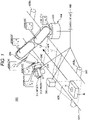
- FIG. 1 shows an overall configuration of a robot system according to a first embodiment.
- FIG. 2 is a flowchart showing a driving process of the robot system.
- FIG. 3 is a flowchart showing a process of an insertion operation.
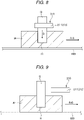
- FIGS. 4 to 9 are cross-sectional views for explaining the insertion operation.
- the upper side in FIGS. 4 to 9 is the upper side in the vertical direction.
- the lower side in FIGS. 4 to 9 is the lower side in the vertical direction.
- a robot system 100 shown in FIG. 1 has a robot 200, a location sensor 300, a control device 400, and a conveyor device 600.
- the conveyor device 600 is driven under the control of the control device 400 and conveys an insertion receiving object W, which is a first target object, along a direction of conveyance 610.
- the control device 400 detects the state of conveyance of the insertion receiving object W, based on image information acquired by the location sensor 300.
- the robot 200 is driven under the control of the control device 400 and performs an insertion operation of inserting an object to be inserted Q, which is a second target object, into a hole H in the insertion receiving object W while following the insertion receiving object W that is being conveyed.
- the insertion receiving object W is any object on which the robot 200 can perform an operation, such as an industrial product like a printer or an automobile, or a component of such a product.
- the insertion receiving object W has a closed-end hole H, and an operation of inserting the object to be inserted Q into this hole H is described as a representative example of the insertion operation.
- the insertion operation is not particularly limited, provided that the second target object is inserted into the first target object.
- the target site where the object to be inserted Q is inserted is not limited to the hole H and may be a groove.
- the robot 200 has a base 230 fixed to a floor, a manipulator 220 supported by the base 230, and an end effector 210 supported by the manipulator 220.
- the manipulator 220 is a robotic arm formed of a plurality of arms coupled together to be rotationally movable.
- the manipulator 220 is a six-axis arm having six joints J1 to J6. Of these joints, the joints J2, J3, J5 are bending joints and the joints J1, J4, J6 are torsion joints.
- the manipulator 220 is not particularly limited, provided that the manipulator 220 can perform the foregoing insertion operation.
- the control device 400 executes feedback control to cause the rotation angles of the joints J1 to J6 indicated by outputs from the encoders E1 to E6 to coincide with their respective target rotation angles during the operation of the robot system 100.
- each of the joints J1 to J6 can be maintained at their respective target rotation angles and the manipulator 220 can be placed in a desired location and attitude. Therefore, the robot 200 can be driven stably in a desired operation.
- the "location and attitude" may be referred to as a "position".
- the end effector 210 is installed via a mechanical interface.
- the end effector 210 has a pair of claw parts 211, 212 and closes and opens the pair of claw parts 211, 212 to grip and release the object to be inserted Q.
- the end effector 210 is not particularly limited, provided that the end effector 210 can grip and release the object to be inserted Q.
- the end effector 210 may be configured to suck the object to be inserted Q via an air chuck or attract the object to be inserted Q via an electromagnetic chuck or the like and thus grip the object to be inserted Q.
- Motors M7, M8 and encoders E7, E8 are installed at the claw parts 211, 212, respectively.
- the control device 400 executes feedback control to cause the separation distance between the claw parts 211, 212 indicated by outputs from the encoders E7, E8 to coincide with a target separation distance, which is a control target, during the operation of the robot system 100.
- a target separation distance which is a control target
- a force sensor 240 acquiring an acting force acting on the insertion receiving object W from the end effector 210 is installed.
- the force sensor 240 measures forces along three axes that act on the object to be inserted Q and torques about the three axes, in a sensor coordinate system, which is a unique three-dimensional orthogonal coordinate system.
- the site where the force sensor 240 is installed is not particularly limited.
- the force sensor 240 may also be installed at the other joints J1 to J5.
- the conveyor device 600 is a belt conveyor and has a belt 620 and conveyor rollers 630a, 630b moving the belt 620.
- the conveyor device 600 is not limited to a belt conveyor and may be any device that can convey the insertion receiving object W along the direction of conveyance 610.
- the conveyor device 600 moves a conveyance surface via the conveyor rollers 630a, 630b and thus conveys the insertion receiving object W placed on the conveyance surface, in the direction of conveyance 610.
- the conveyor roller 630a is provided with a conveyance amount sensor 640 outputting a signal corresponding to the amount of rotation of the conveyor roller 630a to the control device 400.
- the control device 400 executes feedback control to cause the conveyance speed of the insertion receiving object W indicated by the output from the conveyance amount sensor 640 to coincide with a target conveyance speed, which is a control target.
- a target conveyance speed which is a control target.
- the location sensor 300 detects the location of the insertion receiving object W from above the conveyor device 600.
- the location sensor 300 is a camera outputting an image of the insertion receiving object W to the control device 400.
- the location sensor 300 is not limited to a camera.
- a laser range scanner or the like may be employed.
- the location sensor 300 has an angle of view that covers the insertion receiving object W conveyed on the belt 620, as indicated by dashed lines in FIG. 1 .
- a location in the image outputted from the location sensor 300 is associated with a location in the conveyance path by the control device 400. Therefore, when the insertion receiving object W is present within the angle of view of the location sensor 300, the coordinates of the insertion receiving object W can be specified, based on the location of the insertion receiving object W in the image from the location sensor 300.
- the control device 400 controls the driving of the robot 200, the location sensor 300, and the conveyor device 600.
- a control device 400 is formed of a computer, for example, and has a processor (CPU) processing information, a memory communicatively coupled to the processor, and an external interface for coupling to an external device.
- Various programs executable by the processor are saved in the memory.
- the processor can read and execute the various programs stored in the memory.
- a part or all of the components of the control device 400 may be arranged inside the casing of the robot 200.
- the control device 400 may be formed of a plurality of processors.
- step S1 the control device 400 drives the conveyor rollers 630a, 630b of the conveyor device 600 to turn the belt 620 and start to convey the insertion receiving object W. Specifically, the control device 400 executes feedback control to cause the conveyance speed of the insertion receiving object W indicated by the output from the conveyance amount sensor 640 to coincide with a target conveyance speed, which is a control target. Thus, the insertion receiving object W is conveyed in the direction of conveyance 610 at the target conveyance speed.
- step S2 the control device 400 acquires an image of the insertion receiving object W from the location sensor 300 and specifies the coordinates of the insertion receiving object W, based on the location of the insertion receiving object W in the acquired image.
- the control device 400 can also successively acquire images of the insertion receiving object W at very short time intervals from the location sensor 300 and detect the conveyance speed of the insertion receiving object W, based on a change in the coordinates of the insertion receiving object W during the short time.
- step S3 the control device 400 controls the driving of the robot 200 to grip the object to be inserted Q that is to be inserted into the insertion receiving object W.
- Step S3 may be executed prior to or in parallel with step S1 or step S2.
- step S4 the control device 400 controls the driving of the robot 200 to move the manipulator 220 into a standby position.
- the control device 400 initializes the force sensor 240 in a section where the object to be inserted Q moves at a constant velocity along the direction of conveyance 610.
- the output signal from the force sensor 240 in the state where the object to be inserted Q is moved at a constant velocity along the direction of conveyance 610, that is, in the state of uniform motion is zero.
- a noise signal generated due to factors other than the contact with the insertion receiving object W during an insertion operation S7, described later can be reduced, and the state of contact with the insertion receiving object W can be detected more accurately.
- the force sensor 240 can be initialized during the operation of the manipulator 220, the waiting time for the initialization of the force sensor 240 can be reduced and the operation cycle time can be made shorter.
- the timing of initializing the force sensor 240 is not particularly limited, provided that the initialization is performed before the object to be inserted Q is inserted into the insertion receiving object W.
- the initialization may be performed during step S71, described later.
- step S5 the control device 400 controls the driving of the robot 200 to maintain the standby position until the insertion receiving object W reaches a follow start location L1.
- the control device 400 in step S6 controls the driving of the robot 200 and thus causes the object to be inserted Q to follow the insertion receiving object W.
- the control device 400 causes the object to be inserted Qto move parallel to and directly above the insertion receiving object W.
- the insertion operation S7 of inserting the object to be inserted Q into the insertion receiving object W is started.
- the insertion operation S7 will now be described, referring to the flowchart shown in FIG. 3 .
- step S71 the control device 400 controls the driving of the robot 200 to cause the object to be inserted Q to continue following the insertion receiving object W until the insertion receiving object W reaches an operation start location L2 located downstream of the follow start location L1.
- the control device 400 executes the steps described below while causing the object to be inserted Q to follow the insertion receiving object W.
- step S72 the control device 400 controls the driving of the robot 200 to tilt the object to be inserted Q in relation to the insertion receiving object W, as shown in FIG. 4 .
- Tilting in this case means tilting the object to be inserted Q in relation to a completion attitude Pf corresponding to the state where the insertion of the object to be inserted Q into the insertion receiving object W is complete.
- this attitude is also referred to as a "tilted attitude Ps".
- the object to be inserted Q is tilted to the side opposite to the direction of conveyance 610 so that an insertion distal end (lower end) side of the object to be inserted Q is located downstream of an insertion proximal end (upper end) side of the object to be inserted Q along the direction of conveyance 610.
- Step S72 may be executed at any timing before step S73, described later, and may be executed before the insertion operation starts.
- step S73 the control device 400 controls the driving of the robot 200 to move the object to be inserted Q toward the insertion receiving object W along an arrow A indicating the tilting direction of the object to be inserted Q and thus press a lower end surface Q1 of the object to be inserted Q against a first edge part H1 located downstream along the direction of conveyance 610 of the hole H in the insertion receiving object W, while maintaining the object to be inserted Q in the tilted attitude Ps, as shown in FIG. 5 .
- the control device 400 detects the contact between the object to be inserted Q and the first edge part H1, based on the output from the force sensor 240, and controls the press force of the object to be inserted Q against the first edge part H1, based on the output from the force sensor 240.
- the control device 400 executes step S73 by force control. Specifically, the control device 400 executes feedback control to cause the press force indicated by the output from the force sensor 240 to coincide with a target press force, which is a control target.
- a target press force which is a control target.
- the press force can be maintained to be the target press force and the object to be inserted Q can be pressed against the first edge part H1 with a proper force that is neither excessive nor insufficient. Therefore, the subsequent operation can be performed stably. Also, the probability of an unstable relative positional relationship between these two parts due to weak pressing, or misalignment of or damage to the insertion receiving object W due to strong pressing, can be reduced.
- step S74 the control device 400 controls the driving of the robot 200 to move the object to be inserted Q upstream along the direction of conveyance 610, along an arrow B orthogonal to the arrow A, while pressing the lower end surface Q1 against the first edge part H1, and thus press a lateral surface Q2 of the object to be inserted Q against a second edge part H2 located upstream along the direction of conveyance 610 of the hole H, while maintaining the object to be inserted Q in the tilted attitude Ps, as shown in FIG. 6 .
- the control device 400 controls the press force of the object to be inserted Q against the first edge part H1, detects the contact between the lateral surface Q2 and the second edge part H2, and controls the press force of the object to be inserted Q against the second edge part H2, based on the output from the force sensor 240.
- the control device 400 executes step S74 by force control. Specifically, the control device 400 executes feedback control to cause the press force indicated by the output from the force sensor 240 to coincide with a target press force, which is a control target.
- a target press force which is a control target.
- the subsequent operation can be performed stably. Also, the probability of an unstable relative positional relationship between these two parts due to weak pressing, or misalignment of or damage to the insertion receiving object W due to strong pressing, can be reduced. Since the object to be inserted Q is tilted to the side opposite to the direction of conveyance 610, the movement of the lateral surface Q2 and the second edge part H2 toward each other is achieved by the manipulator 220 moving the object to be inserted Q upstream along the direction of conveyance 610, along the arrow B, and by the conveyor device 600 moving the insertion receiving object W in the direction of conveyance 610. Therefore, the distance of movement of the object to be inserted Q by the manipulator 220 can be made shorter and the operation time can be reduced. Also, the movement of the lateral surface Q2 and the second edge part H2 toward each other may be achieved by only the conveyor device 600 moving the insertion receiving object W in the direction of conveyance 610 without the manipulator 220 moving the object to be inserted Q.
- step S75 the control device 400 controls the driving of the robot 200 to rotate the object to be inserted Q as indicated by an arrow C about the second edge part H2 as the fulcrum until the tilt in relation to the completion attitude Pf is substantially eliminated, while pressing the lateral surface Q2 of the object to be inserted Q against the second edge part H2, as shown in FIG. 7 .
- the control device 400 controls the driving of the robot 200 in such a way that the press force of the object to be inserted Q against the second edge part H2 is maintained to be a target press force.
- the control device 400 executes step S75 by force control.
- control device 400 executes feedback control to cause the press force indicated by the output from the force sensor 240 to coincide with the target press force, which is a control target.
- the press force can be maintained to be the target press force and the object to be inserted Q can be rotated while the object to be inserted Q is pressed against the second edge part H2 with a proper force that is neither excessive nor insufficient.
- step S76 the control device 400 controls the driving of the robot 200 to move the object to be inserted Q downward along an arrow D pointing vertically downward and thus insert the object to be inserted Q into the hole H, as shown in FIG. 8 .
- the control device 400 detects the completion of the insertion of the object to be inserted Q, based on the output from the force sensor 240.
- the insertion of the object to be inserted Q into the hole H is thus completed.
- Steps S75, S76 are executed in two actions but may be executed in one action, that is, simultaneously.
- the object to be inserted Q may be energized downward along the arrow D and rotated along the arrow C about the second edge part H2 as the fulcrum at the same time.
- the object to be inserted Q is inserted into the hole H, at the point when the tilt is reduced and the object to be inserted Q is placed in an attitude where the object to be inserted Q can be inserted into the hole H.
- step S77 the control device 400 controls the driving of the robot 200 to release the object to be inserted Q from the end effector 210, as shown in FIG. 9 .
- the control device 400 releases the object to be inserted Q while controlling the state of contact between the end effector 210 and the object to be inserted Q, based on the output from the force sensor 240, so that an excessive stress is not applied to the object to be inserted Q.
- the control device 400 executes feedback control to make the stress indicated by the output from the force sensor 240 equal to or less than a predetermined threshold, during the release operation.
- step S75 the attitude of the object to be inserted Q in relation to the hole H is adjusted while the lateral surface Q2 of the object to be inserted Q is pressed against the hole H. Therefore, the effect thereof is prominent.
- the object to be inserted Q is inserted into the hole H more smoothly and easily than, for example, when the relative position of the object to be inserted Q in relation to the hole H is controlled with no contact between these parts. Therefore, the time taken for the insertion operation S7 is reduced further and the insertion receiving object W can be effectively restrained from moving out of the movement range of the robot 200 before the insertion operation is completed.
- the robot system 100 has been described above.
- Such a robot system 100 has: the conveyor device 600 conveying the insertion receiving object W, which is the first target object; the robot 200 performing the insertion operation S7 of inserting the object to be inserted Q, which is the second target object, into the insertion receiving object W with force control; and the control device 400 controlling the robot 200, as described above.
- the control device 400 controls the driving of the robot and thus performs: step S71 as the follow step of causing the object to be inserted Qto follow the insertion receiving object W from the operation start location L2, based on the conveyance speed of the insertion receiving object W; steps S72, S73, S74 as the contact step of bringing the object to be inserted Q into contact with the insertion receiving object W, the object to be inserted Q being in a tilted attitude in relation to the insertion receiving object W, with the force control; step S75 as the attitude change step of changing the attitude of the object to be inserted Q in such a way that the tilt in relation to the insertion receiving object W is eliminated, while pressing the object to be inserted Q against the insertion receiving object W, with the force control; and step S76 as the insertion step of inserting the object to be inserted Q into the insertion receiving object W.
- the object to be inserted Q before the object to be inserted Q is inserted into the hole H, the object to be inserted Q is pressed against the insertion receiving object W and the attitude of the object to be inserted Q in relation to the insertion receiving object W is adjusted in the pressed state. Therefore, the relative position of the object to be inserted Q in relation to the insertion receiving object W can be easily controlled.
- the object to be inserted Q is inserted into the insertion receiving object W smoothly and easily.
- the time taken for the insertion operation S7 is reduced further and the insertion receiving object W can be effectively restrained from moving out of the movement range of the robot 200 before the insertion operation is completed.
- the robot control method for the robot 200 performing the insertion operation S7 of inserting the object to be inserted Q into the insertion receiving object W conveyed by the conveyor device 600, with force control includes: step S71 as the follow step of causing the object to be inserted Q to follow the insertion receiving object W from the operation start location L2, based on the conveyance speed of the insertion receiving object W; steps S72, S73, S74 as the contact step of bringing the object to be inserted Q into contact with the insertion receiving object W, the object to be inserted Q being in a tilted attitude in relation to the insertion receiving object W, with the force control; step S75 as the attitude change step of changing the attitude of the object to be inserted Q in such a way that the tilt in relation to the insertion receiving object W is eliminated, while pressing the object to be inserted Q against the insertion receiving object W, with the force control; and step S76 as the insertion step of inserting the object to be inserted Q into the insertion receiving object W.
- the object to be inserted Q before the object to be inserted Q is inserted into the hole H, the object to be inserted Q is pressed against the insertion receiving object W and the attitude of the object to be inserted Q in relation to the insertion receiving object W is adjusted in the pressed state. Therefore, the relative position of the object to be inserted Q in relation to the insertion receiving object W can be easily controlled.
- the object to be inserted Q is inserted into the insertion receiving object W smoothly and easily.
- the time taken for the insertion operation S7 is reduced further and the insertion receiving object W can be effectively restrained from moving out of the movement range of the robot 200 before the insertion operation is completed.
- the robot control method also includes step S77 as a release step of releasing the object to be inserted Q with the force control, after step S76.
- step S77 as a release step of releasing the object to be inserted Q with the force control, after step S76.
- the robot 200 has the force sensor 240 used for the force control.
- the robot control method includes step S4 as an initialization step of initializing the force sensor 240 in the state where the movement of the object to be inserted Q is a uniform motion, before steps S72, S73, S74.
- step S4 as an initialization step of initializing the force sensor 240 in the state where the movement of the object to be inserted Q is a uniform motion, before steps S72, S73, S74.
- step S72 the object to be inserted Q is tilted in the direction opposite to the direction of conveyance of the insertion receiving object W, in relation to the insertion receiving object W.
- the object to be inserted Q can be inserted into the insertion receiving object W more smoothly and easily.
- the contact step includes step S73 as a first contact step of bringing the object to be inserted Q into contact with the first edge part H1 located downstream along the direction of conveyance, of the hole H, the object to be inserted Q being in the tilted attitude in relation to the insertion receiving object W, and step S74 as a second contact step of bringing the object to be inserted Q into contact with the second edge part H2 located upstream along the direction of conveyance, of the hole H.
- the attitude of the object to be inserted Q in relation to the insertion receiving object W can be adjusted while the lateral surface Q2 of the object to be inserted Q is pressed against the insertion receiving object W.
- the relative position of the object to be inserted Q in relation to the insertion receiving object W can be accurately controlled.
- FIG. 10 is a flowchart showing a process of an insertion operation according to a second embodiment.
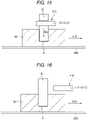
- FIGS. 11 to 16 are cross-sectional views for explaining the insertion operation.
- the upper side in FIGS. 11 to 16 is the upper side in the vertical direction.
- the lower side in FIGS. 11 to 16 is the lower side in the vertical direction.
- This embodiment is similar to the first embodiment except that the process of the insertion operation S7 is different.
- the difference from the foregoing embodiment is mainly described and similar matters are not described further.
- FIGS. 10 to 16 components similar to the components in the foregoing embodiment are denoted by the same reference signs.
- step S71 the control device 400 controls the driving of the robot 200 to cause the object to be inserted Q to continue following the insertion receiving object W until the insertion receiving object W reaches the operation start location L2 located downstream of the follow start location L1.
- the control device 400 executes the steps described below while causing the object to be inserted Q to follow the insertion receiving object W.
- step S72 the control device 400 controls the driving of the robot 200 to tilt the object to be inserted Q in relation to the insertion receiving object W and thus place the object to be inserted Q in the tilted attitude Ps, as shown in FIG. 11 .
- the object to be inserted Q is tilted in the direction of conveyance 610 so that the insertion distal end (lower end) side of the object to be inserted Q is located upstream of the insertion proximal end (upper end) side of the object to be inserted Q along the direction of conveyance 610.
- step S73 the control device 400 controls the driving of the robot 200 to move the object to be inserted Q toward the insertion receiving object W along an arrow AA indicating the tilting direction of the object to be inserted Q and thus press the lower end surface Q1 of the object to be inserted Q against the second edge part H2 of the hole H in the insertion receiving object W, while maintaining the object to be inserted Q in the tilted attitude Ps, as shown in FIG. 12 .
- the control device 400 detects the contact between the object to be inserted Q and the second edge part H2 and controls the press force of the object to be inserted Q against the second edge part H2, based on the output from the force sensor 240.
- step S74 the control device 400 controls the driving of the robot 200 to move the object to be inserted Q downstream along the direction of conveyance 610, along an arrow BB orthogonal to the arrow AA, while pressing the lower end surface Q1 against the second edge part H2, and thus press the lateral surface Q2 of the object to be inserted Q against the first edge part H1, while maintaining the object to be inserted Q in the tilted attitude Ps, as shown in FIG. 13 .
- control device 400 controls the press force of the object to be inserted Q against the second edge part H2, detects the contact between the lateral surface Q2 and the first edge part H1, and controls the press force of the object to be inserted Q against the first edge part H1, based on the output from the force sensor 240.
- step S75 the control device 400 controls the driving of the robot 200 to rotate the object to be inserted Q as indicated by an arrow CC about the first edge part H1 as the fulcrum until the tilt in relation to the completion attitude Pf is substantially eliminated, while pressing the lateral surface Q2 of the object to be inserted Q against the first edge part H1, as shown in FIG. 14 .
- the control device 400 controls the driving of the robot 200 in such a way that the press force of the object to be inserted Q against the first edge part H1 is maintained to be a target press force.
- step S76 the control device 400 controls the driving of the robot 200 to move the object to be inserted Q downward along an arrow DD pointing vertically downward and thus insert the object to be inserted Q into the hole H, as shown in FIG. 15 .
- the control device 400 detects the completion of the insertion of the object to be inserted Q, based on the output from the force sensor 240.
- the insertion of the object to be inserted Q into the hole H is thus completed.
- Steps S75, S76 are executed in two actions but may be executed in one action, that is, simultaneously.
- the object to be inserted Q may be energized downward along the arrow DD and rotated along the arrow CC about the first edge part H1 as the fulcrum at the same time.
- the object to be inserted Q is inserted into the hole H, at the point when the tilt is reduced and the object to be inserted Q is placed in an attitude where the object to be inserted Q can be inserted into the hole H.
- step S77 the control device 400 controls the driving of the robot 200 to release the object to be inserted Q from the end effector 210, as shown in FIG. 16 .
- the control device 400 releases the object to be inserted Q while controlling the state of contact between the end effector 210 and the object to be inserted Q, based on the output from the force sensor 240, so that an excessive stress is not applied to the object to be inserted Q.
- the control device 400 executes feedback control to make the stress indicated by the output from the force sensor 240 equal to or less than a predetermined threshold, during the release operation.
- the object to be inserted Q before the object to be inserted Q is inserted into the hole H, the object to be inserted Q is pressed against the hole H and the attitude of the object to be inserted Q in relation to the hole H is adjusted in the pressed state. Therefore, the relative position of the object to be inserted Q in relation to the hole H can be easily controlled.
- the object to be inserted Q is inserted into the hole H more smoothly and easily than, for example, when the relative position of the object to be inserted Q in relation to the hole H is controlled with no contact between these parts. Therefore, the time taken for the insertion operation S7 is reduced further and the insertion receiving object W can be effectively restrained from moving out of the movement range of the robot 200 before the insertion operation is completed.
- Such a second embodiment can achieve effects similar to those of the first embodiment.
- the robot 200 is fixed to the floor and the manipulator 220 is driven to cause the object to be inserted Q to follow the insertion receiving object W.
- the base 230 may be fixed to a moving unit such as an automatic guided vehicle (AGV), and the moving unit may run parallel to the insertion receiving object W conveyed by the conveyor device 600, thus causing the object to be inserted Qto follow the insertion receiving object W.
- AGV automatic guided vehicle
Landscapes
- Engineering & Computer Science (AREA)
- Robotics (AREA)
- Mechanical Engineering (AREA)
- Human Computer Interaction (AREA)
- Manipulator (AREA)
Abstract
Description
- The present application is based on, and claims priority from
JP Application Serial Number 2020-182752, October 30, 2020 - The present disclosure relates to a robot control method and a robot system.
-
JP-A-2015-174171 - However, in the technique described in
JP-A-2015-174171 - A robot control method according to an aspect of the disclosure is a robot control method for a robot performing an insertion operation of inserting a second target object with force control into a first target object conveyed by a conveyor device is provided. The robot control method includes: a follow step of causing the second target object to follow the first target object from an operation start location, based on a conveyance speed of the first target object; a contact step of bringing the second target object into contact with the first target object, the second target object being in a tilted attitude in relation to the first target object, with the force control; an attitude change step of changing the attitude of the second target object in such a way that the tilt in relation to the first target object is eliminated, while pressing the second target object against the first target object, with the force control; and an insertion step of inserting the second target object into the first target object.
- A robot system according to another aspect of the disclosure includes: a conveyance device conveying a first target object; a robot performing an insertion operation of inserting the first target object into a second target object with force control; and a control device controlling the robot. The control device controls driving of the robot to perform: a follow step of causing the second target object to follow the first target object from an operation start location, based on a conveyance speed of the first target object; a contact step of bringing the second target object into contact with the first target object, the second target object being in a tilted attitude in relation to the first target object, with the force control; an attitude change step of changing the attitude of the second target object in such a way that the tilt in relation to the first target object is eliminated, while pressing the second target object against the first target object, with the force control; and an insertion step of inserting the second target object into the first target object.
-
-
FIG. 1 shows an overall configuration of a robot system according to a first embodiment. -
FIG. 2 is a flowchart showing a driving process of the robot system. -
FIG. 3 is a flowchart showing a process of an insertion operation. -
FIG. 4 is a cross-sectional view for explaining the insertion operation. -
FIG. 5 is a cross-sectional view for explaining the insertion operation. -
FIG. 6 is a cross-sectional view for explaining the insertion operation. -
FIG. 7 is a cross-sectional view for explaining the insertion operation. -
FIG. 8 is a cross-sectional view for explaining the insertion operation. -
FIG. 9 is a cross-sectional view for explaining the insertion operation. -
FIG. 10 is a flowchart showing a process of an insertion operation according to a second embodiment. -
FIG. 11 is a cross-sectional view for explaining the insertion operation. -
FIG. 12 is a cross-sectional view for explaining the insertion operation. -
FIG. 13 is a cross-sectional view for explaining the insertion operation. -
FIG. 14 is a cross-sectional view for explaining the insertion operation. -
FIG. 15 is a cross-sectional view for explaining the insertion operation. -
FIG. 16 is a cross-sectional view for explaining the insertion operation. - Embodiments will now be described with reference to the drawings.
-
FIG. 1 shows an overall configuration of a robot system according to a first embodiment.FIG. 2 is a flowchart showing a driving process of the robot system.FIG. 3 is a flowchart showing a process of an insertion operation.FIGS. 4 to 9 are cross-sectional views for explaining the insertion operation. The upper side inFIGS. 4 to 9 is the upper side in the vertical direction. The lower side inFIGS. 4 to 9 is the lower side in the vertical direction. - A
robot system 100 shown inFIG. 1 has arobot 200, alocation sensor 300, acontrol device 400, and aconveyor device 600. In therobot system 100 having such a configuration, theconveyor device 600 is driven under the control of thecontrol device 400 and conveys an insertion receiving object W, which is a first target object, along a direction ofconveyance 610. Thecontrol device 400 detects the state of conveyance of the insertion receiving object W, based on image information acquired by thelocation sensor 300. Therobot 200 is driven under the control of thecontrol device 400 and performs an insertion operation of inserting an object to be inserted Q, which is a second target object, into a hole H in the insertion receiving object W while following the insertion receiving object W that is being conveyed. The insertion receiving object W is any object on which therobot 200 can perform an operation, such as an industrial product like a printer or an automobile, or a component of such a product. In this embodiment, for the sake of convenience of the description, the insertion receiving object W has a closed-end hole H, and an operation of inserting the object to be inserted Q into this hole H is described as a representative example of the insertion operation. However, the insertion operation is not particularly limited, provided that the second target object is inserted into the first target object. The target site where the object to be inserted Q is inserted is not limited to the hole H and may be a groove. - The
robot 200 has abase 230 fixed to a floor, amanipulator 220 supported by thebase 230, and anend effector 210 supported by themanipulator 220. Themanipulator 220 is a robotic arm formed of a plurality of arms coupled together to be rotationally movable. In this embodiment, themanipulator 220 is a six-axis arm having six joints J1 to J6. Of these joints, the joints J2, J3, J5 are bending joints and the joints J1, J4, J6 are torsion joints. However, themanipulator 220 is not particularly limited, provided that themanipulator 220 can perform the foregoing insertion operation. - Motors M1, M2, M3, M4, M5, M6 and encoders E1, E2, E3, E4, E5, E6 are installed at the joints J1, J2, J3, J4, J5, J6, respectively. The
control device 400 executes feedback control to cause the rotation angles of the joints J1 to J6 indicated by outputs from the encoders E1 to E6 to coincide with their respective target rotation angles during the operation of therobot system 100. Thus, each of the joints J1 to J6 can be maintained at their respective target rotation angles and themanipulator 220 can be placed in a desired location and attitude. Therefore, therobot 200 can be driven stably in a desired operation. In the description below, the "location and attitude" may be referred to as a "position". - At the distal end part of the
manipulator 220, that is, at the joint J6, theend effector 210 is installed via a mechanical interface. Theend effector 210 has a pair ofclaw parts claw parts end effector 210 is not particularly limited, provided that theend effector 210 can grip and release the object to be inserted Q. For example, theend effector 210 may be configured to suck the object to be inserted Q via an air chuck or attract the object to be inserted Q via an electromagnetic chuck or the like and thus grip the object to be inserted Q. - Motors M7, M8 and encoders E7, E8 are installed at the
claw parts control device 400 executes feedback control to cause the separation distance between theclaw parts robot system 100. Thus, the separation distance between theclaw parts - At the joint J6 of the
manipulator 220, aforce sensor 240 acquiring an acting force acting on the insertion receiving object W from theend effector 210 is installed. Theforce sensor 240 measures forces along three axes that act on the object to be inserted Q and torques about the three axes, in a sensor coordinate system, which is a unique three-dimensional orthogonal coordinate system. The site where theforce sensor 240 is installed is not particularly limited. Theforce sensor 240 may also be installed at the other joints J1 to J5. - The
conveyor device 600 is a belt conveyor and has abelt 620 andconveyor rollers belt 620. However, theconveyor device 600 is not limited to a belt conveyor and may be any device that can convey the insertion receiving object W along the direction ofconveyance 610. - The
conveyor device 600 moves a conveyance surface via theconveyor rollers conveyance 610. Theconveyor roller 630a is provided with aconveyance amount sensor 640 outputting a signal corresponding to the amount of rotation of theconveyor roller 630a to thecontrol device 400. Thecontrol device 400 executes feedback control to cause the conveyance speed of the insertion receiving object W indicated by the output from theconveyance amount sensor 640 to coincide with a target conveyance speed, which is a control target. Thus, the conveyance speed of the insertion receiving object W can be maintained to be the target conveyance speed and the insertion receiving object W can be conveyed stably at a desired speed. - The
location sensor 300 detects the location of the insertion receiving object W from above theconveyor device 600. Thelocation sensor 300 is a camera outputting an image of the insertion receiving object W to thecontrol device 400. However, thelocation sensor 300 is not limited to a camera. For example, a laser range scanner or the like may be employed. Thelocation sensor 300 has an angle of view that covers the insertion receiving object W conveyed on thebelt 620, as indicated by dashed lines inFIG. 1 . A location in the image outputted from thelocation sensor 300 is associated with a location in the conveyance path by thecontrol device 400. Therefore, when the insertion receiving object W is present within the angle of view of thelocation sensor 300, the coordinates of the insertion receiving object W can be specified, based on the location of the insertion receiving object W in the image from thelocation sensor 300. - The
control device 400 controls the driving of therobot 200, thelocation sensor 300, and theconveyor device 600. Such acontrol device 400 is formed of a computer, for example, and has a processor (CPU) processing information, a memory communicatively coupled to the processor, and an external interface for coupling to an external device. Various programs executable by the processor are saved in the memory. The processor can read and execute the various programs stored in the memory. A part or all of the components of thecontrol device 400 may be arranged inside the casing of therobot 200. Also, thecontrol device 400 may be formed of a plurality of processors. - The overall configuration of the
robot system 100 has been described. An insertion operation using therobot system 100 will now be described, referring to the flowchart shown inFIG. 2 . - First, in step S1, the
control device 400 drives theconveyor rollers conveyor device 600 to turn thebelt 620 and start to convey the insertion receiving object W. Specifically, thecontrol device 400 executes feedback control to cause the conveyance speed of the insertion receiving object W indicated by the output from theconveyance amount sensor 640 to coincide with a target conveyance speed, which is a control target. Thus, the insertion receiving object W is conveyed in the direction ofconveyance 610 at the target conveyance speed. - Next, in step S2, the
control device 400 acquires an image of the insertion receiving object W from thelocation sensor 300 and specifies the coordinates of the insertion receiving object W, based on the location of the insertion receiving object W in the acquired image. As the coordinates and the conveyance speed of the insertion receiving object W are thus made known, which point the insertion receiving object W passes at what time is found. Thecontrol device 400 can also successively acquire images of the insertion receiving object W at very short time intervals from thelocation sensor 300 and detect the conveyance speed of the insertion receiving object W, based on a change in the coordinates of the insertion receiving object W during the short time. - Next, in step S3, the
control device 400 controls the driving of therobot 200 to grip the object to be inserted Q that is to be inserted into the insertion receiving object W. Step S3 may be executed prior to or in parallel with step S1 or step S2. - Next, in step S4, the
control device 400 controls the driving of therobot 200 to move themanipulator 220 into a standby position. In the course of moving themanipulator 220 into the standby position, thecontrol device 400 initializes theforce sensor 240 in a section where the object to be inserted Q moves at a constant velocity along the direction ofconveyance 610. In short, the output signal from theforce sensor 240 in the state where the object to be inserted Q is moved at a constant velocity along the direction ofconveyance 610, that is, in the state of uniform motion, is zero. Thus, a noise signal generated due to factors other than the contact with the insertion receiving object W during an insertion operation S7, described later, can be reduced, and the state of contact with the insertion receiving object W can be detected more accurately. Therefore, accurate force control can be performed and the insertion operation S7 can be performed accurately and smoothly. Also, since theforce sensor 240 can be initialized during the operation of themanipulator 220, the waiting time for the initialization of theforce sensor 240 can be reduced and the operation cycle time can be made shorter. The timing of initializing theforce sensor 240 is not particularly limited, provided that the initialization is performed before the object to be inserted Q is inserted into the insertion receiving object W. For example, the initialization may be performed during step S71, described later. - Next, in step S5, the
control device 400 controls the driving of therobot 200 to maintain the standby position until the insertion receiving object W reaches a follow start location L1. When the insertion receiving object W has reached the follow start location L1, thecontrol device 400 in step S6 controls the driving of therobot 200 and thus causes the object to be inserted Q to follow the insertion receiving object W. Specifically, thecontrol device 400 causes the object to be inserted Qto move parallel to and directly above the insertion receiving object W. After a preparation step as described above, the insertion operation S7 of inserting the object to be inserted Q into the insertion receiving object W is started. The insertion operation S7 will now be described, referring to the flowchart shown inFIG. 3 . - In the insertion operation S7, first, in step S71, the
control device 400 controls the driving of therobot 200 to cause the object to be inserted Q to continue following the insertion receiving object W until the insertion receiving object W reaches an operation start location L2 located downstream of the follow start location L1. When the insertion receiving object W has reached the operation start location L2, thecontrol device 400 executes the steps described below while causing the object to be inserted Q to follow the insertion receiving object W. - First, in step S72, the
control device 400 controls the driving of therobot 200 to tilt the object to be inserted Q in relation to the insertion receiving object W, as shown inFIG. 4 . Tilting in this case means tilting the object to be inserted Q in relation to a completion attitude Pf corresponding to the state where the insertion of the object to be inserted Q into the insertion receiving object W is complete. Hereinafter, this attitude is also referred to as a "tilted attitude Ps". Particularly in the tilted attitude Ps in this embodiment, the object to be inserted Q is tilted to the side opposite to the direction ofconveyance 610 so that an insertion distal end (lower end) side of the object to be inserted Q is located downstream of an insertion proximal end (upper end) side of the object to be inserted Q along the direction ofconveyance 610. Step S72 may be executed at any timing before step S73, described later, and may be executed before the insertion operation starts. - Next, in step S73, the
control device 400 controls the driving of therobot 200 to move the object to be inserted Q toward the insertion receiving object W along an arrow A indicating the tilting direction of the object to be inserted Q and thus press a lower end surface Q1 of the object to be inserted Q against a first edge part H1 located downstream along the direction ofconveyance 610 of the hole H in the insertion receiving object W, while maintaining the object to be inserted Q in the tilted attitude Ps, as shown inFIG. 5 . At this point, thecontrol device 400 detects the contact between the object to be inserted Q and the first edge part H1, based on the output from theforce sensor 240, and controls the press force of the object to be inserted Q against the first edge part H1, based on the output from theforce sensor 240. In short, thecontrol device 400 executes step S73 by force control. Specifically, thecontrol device 400 executes feedback control to cause the press force indicated by the output from theforce sensor 240 to coincide with a target press force, which is a control target. Thus, the press force can be maintained to be the target press force and the object to be inserted Q can be pressed against the first edge part H1 with a proper force that is neither excessive nor insufficient. Therefore, the subsequent operation can be performed stably. Also, the probability of an unstable relative positional relationship between these two parts due to weak pressing, or misalignment of or damage to the insertion receiving object W due to strong pressing, can be reduced. - Next, in step S74, the
control device 400 controls the driving of therobot 200 to move the object to be inserted Q upstream along the direction ofconveyance 610, along an arrow B orthogonal to the arrow A, while pressing the lower end surface Q1 against the first edge part H1, and thus press a lateral surface Q2 of the object to be inserted Q against a second edge part H2 located upstream along the direction ofconveyance 610 of the hole H, while maintaining the object to be inserted Q in the tilted attitude Ps, as shown inFIG. 6 . At this point, thecontrol device 400 controls the press force of the object to be inserted Q against the first edge part H1, detects the contact between the lateral surface Q2 and the second edge part H2, and controls the press force of the object to be inserted Q against the second edge part H2, based on the output from theforce sensor 240. In short, thecontrol device 400 executes step S74 by force control. Specifically, thecontrol device 400 executes feedback control to cause the press force indicated by the output from theforce sensor 240 to coincide with a target press force, which is a control target. Thus, the press force can be maintained to be the target press force and the object to be inserted Q can be pressed against the first edge part H1 and the second edge part H2 with a proper force that is neither excessive nor insufficient. Therefore, the subsequent operation can be performed stably. Also, the probability of an unstable relative positional relationship between these two parts due to weak pressing, or misalignment of or damage to the insertion receiving object W due to strong pressing, can be reduced. Since the object to be inserted Q is tilted to the side opposite to the direction ofconveyance 610, the movement of the lateral surface Q2 and the second edge part H2 toward each other is achieved by themanipulator 220 moving the object to be inserted Q upstream along the direction ofconveyance 610, along the arrow B, and by theconveyor device 600 moving the insertion receiving object W in the direction ofconveyance 610. Therefore, the distance of movement of the object to be inserted Q by themanipulator 220 can be made shorter and the operation time can be reduced. Also, the movement of the lateral surface Q2 and the second edge part H2 toward each other may be achieved by only theconveyor device 600 moving the insertion receiving object W in the direction ofconveyance 610 without themanipulator 220 moving the object to be inserted Q. - Next, in step S75, the
control device 400 controls the driving of therobot 200 to rotate the object to be inserted Q as indicated by an arrow C about the second edge part H2 as the fulcrum until the tilt in relation to the completion attitude Pf is substantially eliminated, while pressing the lateral surface Q2 of the object to be inserted Q against the second edge part H2, as shown inFIG. 7 . At this point, thecontrol device 400 controls the driving of therobot 200 in such a way that the press force of the object to be inserted Q against the second edge part H2 is maintained to be a target press force. In short, thecontrol device 400 executes step S75 by force control. Specifically, thecontrol device 400 executes feedback control to cause the press force indicated by the output from theforce sensor 240 to coincide with the target press force, which is a control target. Thus, the press force can be maintained to be the target press force and the object to be inserted Q can be rotated while the object to be inserted Q is pressed against the second edge part H2 with a proper force that is neither excessive nor insufficient. - Next, in step S76, the
control device 400 controls the driving of therobot 200 to move the object to be inserted Q downward along an arrow D pointing vertically downward and thus insert the object to be inserted Q into the hole H, as shown inFIG. 8 . At this point, thecontrol device 400 detects the completion of the insertion of the object to be inserted Q, based on the output from theforce sensor 240. The insertion of the object to be inserted Q into the hole H is thus completed. Steps S75, S76 are executed in two actions but may be executed in one action, that is, simultaneously. In short, the object to be inserted Q may be energized downward along the arrow D and rotated along the arrow C about the second edge part H2 as the fulcrum at the same time. Thus, the object to be inserted Q is inserted into the hole H, at the point when the tilt is reduced and the object to be inserted Q is placed in an attitude where the object to be inserted Q can be inserted into the hole H. - Next, in step S77, the
control device 400 controls the driving of therobot 200 to release the object to be inserted Q from theend effector 210, as shown inFIG. 9 . At this point, thecontrol device 400 releases the object to be inserted Q while controlling the state of contact between theend effector 210 and the object to be inserted Q, based on the output from theforce sensor 240, so that an excessive stress is not applied to the object to be inserted Q. In short, thecontrol device 400 executes feedback control to make the stress indicated by the output from theforce sensor 240 equal to or less than a predetermined threshold, during the release operation. Thus, the application of an excessive stress to the object to be inserted Q, when being released, can be restrained. - In such a method, before the object to be inserted Q is inserted into the hole H, the object to be inserted Q is pressed against the hole H and the attitude of the object to be inserted Q in relation to the hole H is adjusted in the pressed state. Therefore, the relative position of the object to be inserted Q in relation to the hole H can be easily controlled. Particularly in this embodiment, in step S75, the attitude of the object to be inserted Q in relation to the hole H is adjusted while the lateral surface Q2 of the object to be inserted Q is pressed against the hole H. Therefore, the effect thereof is prominent. The object to be inserted Q is inserted into the hole H more smoothly and easily than, for example, when the relative position of the object to be inserted Q in relation to the hole H is controlled with no contact between these parts. Therefore, the time taken for the insertion operation S7 is reduced further and the insertion receiving object W can be effectively restrained from moving out of the movement range of the
robot 200 before the insertion operation is completed. - The
robot system 100 has been described above. Such arobot system 100 has: theconveyor device 600 conveying the insertion receiving object W, which is the first target object; therobot 200 performing the insertion operation S7 of inserting the object to be inserted Q, which is the second target object, into the insertion receiving object W with force control; and thecontrol device 400 controlling therobot 200, as described above. Thecontrol device 400 controls the driving of the robot and thus performs: step S71 as the follow step of causing the object to be inserted Qto follow the insertion receiving object W from the operation start location L2, based on the conveyance speed of the insertion receiving object W; steps S72, S73, S74 as the contact step of bringing the object to be inserted Q into contact with the insertion receiving object W, the object to be inserted Q being in a tilted attitude in relation to the insertion receiving object W, with the force control; step S75 as the attitude change step of changing the attitude of the object to be inserted Q in such a way that the tilt in relation to the insertion receiving object W is eliminated, while pressing the object to be inserted Q against the insertion receiving object W, with the force control; and step S76 as the insertion step of inserting the object to be inserted Q into the insertion receiving object W. In such a method, before the object to be inserted Q is inserted into the hole H, the object to be inserted Q is pressed against the insertion receiving object W and the attitude of the object to be inserted Q in relation to the insertion receiving object W is adjusted in the pressed state. Therefore, the relative position of the object to be inserted Q in relation to the insertion receiving object W can be easily controlled. The object to be inserted Q is inserted into the insertion receiving object W smoothly and easily. Thus, the time taken for the insertion operation S7 is reduced further and the insertion receiving object W can be effectively restrained from moving out of the movement range of therobot 200 before the insertion operation is completed. - As described above, the robot control method for the robot 200 performing the insertion operation S7 of inserting the object to be inserted Q into the insertion receiving object W conveyed by the conveyor device 600, with force control, includes: step S71 as the follow step of causing the object to be inserted Q to follow the insertion receiving object W from the operation start location L2, based on the conveyance speed of the insertion receiving object W; steps S72, S73, S74 as the contact step of bringing the object to be inserted Q into contact with the insertion receiving object W, the object to be inserted Q being in a tilted attitude in relation to the insertion receiving object W, with the force control; step S75 as the attitude change step of changing the attitude of the object to be inserted Q in such a way that the tilt in relation to the insertion receiving object W is eliminated, while pressing the object to be inserted Q against the insertion receiving object W, with the force control; and step S76 as the insertion step of inserting the object to be inserted Q into the insertion receiving object W. In such a method, before the object to be inserted Q is inserted into the hole H, the object to be inserted Q is pressed against the insertion receiving object W and the attitude of the object to be inserted Q in relation to the insertion receiving object W is adjusted in the pressed state. Therefore, the relative position of the object to be inserted Q in relation to the insertion receiving object W can be easily controlled. The object to be inserted Q is inserted into the insertion receiving object W smoothly and easily. Thus, the time taken for the insertion operation S7 is reduced further and the insertion receiving object W can be effectively restrained from moving out of the movement range of the
robot 200 before the insertion operation is completed. - As described above, the robot control method also includes step S77 as a release step of releasing the object to be inserted Q with the force control, after step S76. Thus, the application of an excessive stress to the object to be inserted Q, when being released, can be restrained.
- As described above, the
robot 200 has theforce sensor 240 used for the force control. The robot control method includes step S4 as an initialization step of initializing theforce sensor 240 in the state where the movement of the object to be inserted Q is a uniform motion, before steps S72, S73, S74. Thus, a noise signal generated due to factors other than the contact with the insertion receiving object W during the insertion operation S7 can be reduced, and the state of contact with the insertion receiving object W can be detected more accurately. Therefore, accurate force control can be performed and the insertion operation S7 can be performed accurately and smoothly. - As described above, in step S72, the object to be inserted Q is tilted in the direction opposite to the direction of conveyance of the insertion receiving object W, in relation to the insertion receiving object W. Thus, the object to be inserted Q can be inserted into the insertion receiving object W more smoothly and easily.
- As described above, the hole H into which the object to be inserted Q is inserted is provided in the insertion receiving object W. The contact step includes step S73 as a first contact step of bringing the object to be inserted Q into contact with the first edge part H1 located downstream along the direction of conveyance, of the hole H, the object to be inserted Q being in the tilted attitude in relation to the insertion receiving object W, and step S74 as a second contact step of bringing the object to be inserted Q into contact with the second edge part H2 located upstream along the direction of conveyance, of the hole H. In such a method, the attitude of the object to be inserted Q in relation to the insertion receiving object W can be adjusted while the lateral surface Q2 of the object to be inserted Q is pressed against the insertion receiving object W. Thus, the relative position of the object to be inserted Q in relation to the insertion receiving object W can be accurately controlled.
-
FIG. 10 is a flowchart showing a process of an insertion operation according to a second embodiment.FIGS. 11 to 16 are cross-sectional views for explaining the insertion operation. The upper side inFIGS. 11 to 16 is the upper side in the vertical direction. The lower side inFIGS. 11 to 16 is the lower side in the vertical direction. - This embodiment is similar to the first embodiment except that the process of the insertion operation S7 is different. In the description below, the difference from the foregoing embodiment is mainly described and similar matters are not described further. In
FIGS. 10 to 16 , components similar to the components in the foregoing embodiment are denoted by the same reference signs. - The insertion operation S7 will now be described. First, in step S71, the
control device 400 controls the driving of therobot 200 to cause the object to be inserted Q to continue following the insertion receiving object W until the insertion receiving object W reaches the operation start location L2 located downstream of the follow start location L1. When the insertion receiving object W has reached the operation start location L2, thecontrol device 400 executes the steps described below while causing the object to be inserted Q to follow the insertion receiving object W. - First, in step S72, the
control device 400 controls the driving of therobot 200 to tilt the object to be inserted Q in relation to the insertion receiving object W and thus place the object to be inserted Q in the tilted attitude Ps, as shown inFIG. 11 . In the tilted attitude Ps in this embodiment, the object to be inserted Q is tilted in the direction ofconveyance 610 so that the insertion distal end (lower end) side of the object to be inserted Q is located upstream of the insertion proximal end (upper end) side of the object to be inserted Q along the direction ofconveyance 610. - Next, in step S73, the
control device 400 controls the driving of therobot 200 to move the object to be inserted Q toward the insertion receiving object W along an arrow AA indicating the tilting direction of the object to be inserted Q and thus press the lower end surface Q1 of the object to be inserted Q against the second edge part H2 of the hole H in the insertion receiving object W, while maintaining the object to be inserted Q in the tilted attitude Ps, as shown inFIG. 12 . At this point, thecontrol device 400 detects the contact between the object to be inserted Q and the second edge part H2 and controls the press force of the object to be inserted Q against the second edge part H2, based on the output from theforce sensor 240. - Next, in step S74, the
control device 400 controls the driving of therobot 200 to move the object to be inserted Q downstream along the direction ofconveyance 610, along an arrow BB orthogonal to the arrow AA, while pressing the lower end surface Q1 against the second edge part H2, and thus press the lateral surface Q2 of the object to be inserted Q against the first edge part H1, while maintaining the object to be inserted Q in the tilted attitude Ps, as shown inFIG. 13 . At this point, thecontrol device 400 controls the press force of the object to be inserted Q against the second edge part H2, detects the contact between the lateral surface Q2 and the first edge part H1, and controls the press force of the object to be inserted Q against the first edge part H1, based on the output from theforce sensor 240. - Next, in step S75, the
control device 400 controls the driving of therobot 200 to rotate the object to be inserted Q as indicated by an arrow CC about the first edge part H1 as the fulcrum until the tilt in relation to the completion attitude Pf is substantially eliminated, while pressing the lateral surface Q2 of the object to be inserted Q against the first edge part H1, as shown inFIG. 14 . At this point, thecontrol device 400 controls the driving of therobot 200 in such a way that the press force of the object to be inserted Q against the first edge part H1 is maintained to be a target press force. - Next, in step S76, the
control device 400 controls the driving of therobot 200 to move the object to be inserted Q downward along an arrow DD pointing vertically downward and thus insert the object to be inserted Q into the hole H, as shown inFIG. 15 . At this point, thecontrol device 400 detects the completion of the insertion of the object to be inserted Q, based on the output from theforce sensor 240. The insertion of the object to be inserted Q into the hole H is thus completed. Steps S75, S76 are executed in two actions but may be executed in one action, that is, simultaneously. In short, the object to be inserted Q may be energized downward along the arrow DD and rotated along the arrow CC about the first edge part H1 as the fulcrum at the same time. Thus, the object to be inserted Q is inserted into the hole H, at the point when the tilt is reduced and the object to be inserted Q is placed in an attitude where the object to be inserted Q can be inserted into the hole H. - Next, in step S77, the
control device 400 controls the driving of therobot 200 to release the object to be inserted Q from theend effector 210, as shown inFIG. 16 . At this point, thecontrol device 400 releases the object to be inserted Q while controlling the state of contact between theend effector 210 and the object to be inserted Q, based on the output from theforce sensor 240, so that an excessive stress is not applied to the object to be inserted Q. In short, thecontrol device 400 executes feedback control to make the stress indicated by the output from theforce sensor 240 equal to or less than a predetermined threshold, during the release operation. Thus, the application of an excessive stress to the object to be inserted Q, when being released, can be restrained. - In such a method, before the object to be inserted Q is inserted into the hole H, the object to be inserted Q is pressed against the hole H and the attitude of the object to be inserted Q in relation to the hole H is adjusted in the pressed state. Therefore, the relative position of the object to be inserted Q in relation to the hole H can be easily controlled. The object to be inserted Q is inserted into the hole H more smoothly and easily than, for example, when the relative position of the object to be inserted Q in relation to the hole H is controlled with no contact between these parts. Therefore, the time taken for the insertion operation S7 is reduced further and the insertion receiving object W can be effectively restrained from moving out of the movement range of the
robot 200 before the insertion operation is completed. - Such a second embodiment can achieve effects similar to those of the first embodiment.
- The robot control method and the robot system according to the disclosure have been described, based on the illustrated embodiments. However, the disclosure is not limited to these embodiments. The configuration of each part can be replaced with any configuration having similar functions. Any other component may be added to the disclosure. Also, the embodiments may be suitably combined together. Another process may be added to the insertion operation.
- In the embodiments, the
robot 200 is fixed to the floor and themanipulator 220 is driven to cause the object to be inserted Q to follow the insertion receiving object W. However, this is not limiting. For example, thebase 230 may be fixed to a moving unit such as an automatic guided vehicle (AGV), and the moving unit may run parallel to the insertion receiving object W conveyed by theconveyor device 600, thus causing the object to be inserted Qto follow the insertion receiving object W.
Claims (6)
- A robot control method for a robot performing an insertion operation of inserting a second target object with force control into a first target object conveyed by a conveyor device, the robot control method comprising:a follow step of causing the second target object to follow the first target object from an operation start location, based on a conveyance speed of the first target object;a contact step of bringing the second target object into contact with the first target object, the second target object being in a tilted attitude in relation to the first target object, with the force control;an attitude change step of changing the attitude of the second target object in such a way that the tilt in relation to the first target object is eliminated, while pressing the second target object against the first target object, with the force control; andan insertion step of inserting the second target object into the first target object.
- The robot control method according to claim 1, further comprising:
a release step of releasing the second target object with the force control, after the insertion step. - The robot control method according to claims 1 and 2, whereinthe robot has a force sensor used for the force control, andthe robot control method further comprises an initialization step of initializing the force sensor in a state where a movement of the second target object is a uniform motion, before the contact step.
- The robot control method according to any one of claims 1 to 3, wherein
in the contact step, the second target object is tilted in a direction opposite to a direction of conveyance of the first target object, in relation to the first target object. - The robot control method according to claim 4, whereina hole into which the second target object is inserted is provided in the first target object, andthe contact step includesa first contact step of bringing the second target object into contact with a first edge part located downstream along the direction of conveyance, of the hole, the second target object being in the tilted attitude in relation to the first target object, anda second contact step of bringing the second target object into contact with a second edge part located upstream along the direction of conveyance, of the hole.
- A robot system comprising:a conveyance device conveying a first target object;a robot performing an insertion operation of inserting the first target object into a second target object with force control; anda control device controlling the robot,the control device controlling driving of the robot to perform:a follow step of causing the second target object to follow the first target object from an operation start location, based on a conveyance speed of the first target object;a contact step of bringing the second target object into contact with the first target object, the second target object being in a tilted attitude in relation to the first target object, with the force control;an attitude change step of changing the attitude of the second target object in such a way that the tilt in relation to the first target object is eliminated, while pressing the second target object against the first target object, with the force control; andan insertion step of inserting the second target object into the first target object.
Applications Claiming Priority (1)
| Application Number | Priority Date | Filing Date | Title |
|---|---|---|---|
| JP2020182752A JP7563117B2 (en) | 2020-10-30 | 2020-10-30 | Robot control method and robot system |
Publications (2)
| Publication Number | Publication Date |
|---|---|
| EP3991923A1 true EP3991923A1 (en) | 2022-05-04 |
| EP3991923B1 EP3991923B1 (en) | 2025-02-12 |
Family
ID=78621645
Family Applications (1)
| Application Number | Title | Priority Date | Filing Date |
|---|---|---|---|
| EP21204428.3A Active EP3991923B1 (en) | 2020-10-30 | 2021-10-25 | Robot control method and robot system |
Country Status (4)
| Country | Link |
|---|---|
| US (1) | US11945122B2 (en) |
| EP (1) | EP3991923B1 (en) |
| JP (1) | JP7563117B2 (en) |
| CN (1) | CN114434438B (en) |
Families Citing this family (4)
| Publication number | Priority date | Publication date | Assignee | Title |
|---|---|---|---|---|
| CN113829347B (en) | 2021-09-30 | 2023-08-15 | 上海傅利叶智能科技有限公司 | Robot control method and device based on physical engine and rehabilitation robot |
| WO2023166588A1 (en) * | 2022-03-02 | 2023-09-07 | ファナック株式会社 | Work robot system |
| WO2024228231A1 (en) * | 2023-05-01 | 2024-11-07 | 株式会社ニコン | Control system, robot system, control method, and computer program |
| WO2025079271A1 (en) * | 2023-10-13 | 2025-04-17 | ヤマハ発動機株式会社 | System for performing work on object and method for calculating reference position |
Citations (7)
| Publication number | Priority date | Publication date | Assignee | Title |
|---|---|---|---|---|
| US20080267737A1 (en) * | 2007-04-24 | 2008-10-30 | Fanuc Ltd | Fitting device |
| JP2010137299A (en) * | 2008-12-09 | 2010-06-24 | Yaskawa Electric Corp | Control method of assembly work robot |
| JP2015174171A (en) | 2014-03-14 | 2015-10-05 | オムロン株式会社 | robot control device |
| EP3275603A2 (en) * | 2016-07-27 | 2018-01-31 | Seiko Epson Corporation | Control device, robot, and robot system |
| US20180339414A1 (en) * | 2017-05-25 | 2018-11-29 | Seiko Epson Corporation | Control Device And Robot System |
| US20190275678A1 (en) * | 2016-11-11 | 2019-09-12 | Seiko Epson Corporation | Robot control device, robot, robot system, and robot control method |
| JP2020182752A (en) | 2019-05-07 | 2020-11-12 | 株式会社英工芸 | Accessory |
Family Cites Families (16)
| Publication number | Priority date | Publication date | Assignee | Title |
|---|---|---|---|---|
| JPH07115313B2 (en) * | 1986-03-20 | 1995-12-13 | 株式会社日立製作所 | Robot device |
| JPH09243335A (en) * | 1996-03-11 | 1997-09-19 | Akita Pref Gov | Detecting device for inclination angle of rod-shaped body |
| JP4271249B2 (en) * | 2007-06-14 | 2009-06-03 | ファナック株式会社 | Mating device |
| JP5438747B2 (en) * | 2011-12-16 | 2014-03-12 | 本田技研工業株式会社 | Work work system |
| JP5915214B2 (en) * | 2012-02-01 | 2016-05-11 | セイコーエプソン株式会社 | Robot apparatus, assembling method, and assembling program |
| JP2015000455A (en) * | 2013-06-17 | 2015-01-05 | キヤノン株式会社 | Robot apparatus and control method of robot apparatus |
| CN104608113B (en) * | 2013-11-01 | 2018-07-17 | 精工爱普生株式会社 | Robot, robot system and robot controller |
| JP6361207B2 (en) * | 2014-03-24 | 2018-07-25 | セイコーエプソン株式会社 | Robot, robot system and robot controller |
| JP6307838B2 (en) * | 2013-11-01 | 2018-04-11 | セイコーエプソン株式会社 | Robot, robot system and control device |
| KR20180137548A (en) * | 2016-04-24 | 2018-12-27 | 프랜카 에미카 게엠바하 | How to insert an object into the object storage area using a robot manipulator |
| EP3479878A1 (en) * | 2017-11-02 | 2019-05-08 | Pin Marketing S.L. | Device and method for setting up at least one bowling pin |
| JP6973119B2 (en) * | 2018-01-26 | 2021-11-24 | セイコーエプソン株式会社 | Robot control device and robot system |
| JP6703018B2 (en) * | 2018-02-01 | 2020-06-03 | ファナック株式会社 | Work robot system |
| CN109249392B (en) * | 2018-08-31 | 2021-03-23 | 先临三维科技股份有限公司 | Calibration method, calibration element, device, equipment and medium for workpiece gripping system |
| CN109348700B (en) * | 2018-09-05 | 2020-10-27 | 鲁班嫡系机器人(深圳)有限公司 | Mobile plug-in method and plug-in device |
| JP7154072B2 (en) | 2018-09-11 | 2022-10-17 | 三菱電機株式会社 | Transfer device and transfer robot |
-
2020
- 2020-10-30 JP JP2020182752A patent/JP7563117B2/en active Active
-
2021
- 2021-10-25 EP EP21204428.3A patent/EP3991923B1/en active Active
- 2021-10-27 CN CN202111257114.0A patent/CN114434438B/en active Active
- 2021-10-29 US US17/514,147 patent/US11945122B2/en active Active
Patent Citations (7)
| Publication number | Priority date | Publication date | Assignee | Title |
|---|---|---|---|---|
| US20080267737A1 (en) * | 2007-04-24 | 2008-10-30 | Fanuc Ltd | Fitting device |
| JP2010137299A (en) * | 2008-12-09 | 2010-06-24 | Yaskawa Electric Corp | Control method of assembly work robot |
| JP2015174171A (en) | 2014-03-14 | 2015-10-05 | オムロン株式会社 | robot control device |
| EP3275603A2 (en) * | 2016-07-27 | 2018-01-31 | Seiko Epson Corporation | Control device, robot, and robot system |
| US20190275678A1 (en) * | 2016-11-11 | 2019-09-12 | Seiko Epson Corporation | Robot control device, robot, robot system, and robot control method |
| US20180339414A1 (en) * | 2017-05-25 | 2018-11-29 | Seiko Epson Corporation | Control Device And Robot System |
| JP2020182752A (en) | 2019-05-07 | 2020-11-12 | 株式会社英工芸 | Accessory |
Also Published As
| Publication number | Publication date |
|---|---|
| JP7563117B2 (en) | 2024-10-08 |
| CN114434438A (en) | 2022-05-06 |
| EP3991923B1 (en) | 2025-02-12 |
| JP2022073012A (en) | 2022-05-17 |
| US20220134564A1 (en) | 2022-05-05 |
| US11945122B2 (en) | 2024-04-02 |
| CN114434438B (en) | 2023-12-26 |
Similar Documents
| Publication | Publication Date | Title |
|---|---|---|
| EP3991923B1 (en) | Robot control method and robot system | |
| US10456917B2 (en) | Robot system including a plurality of robots, robot controller and robot control method | |
| US11541545B2 (en) | Information processing apparatus, information processing method, and system | |
| JP6646026B2 (en) | Work system, work execution method for article, and robot | |
| KR100522653B1 (en) | Device for Handling a Robot | |
| KR102226986B1 (en) | Automatic apparatus and position detecting apparatus | |
| EP4032663B1 (en) | Work robot and work system | |
| JP3002097B2 (en) | Visual tracking method | |
| CN109922931B (en) | Robot control device, robot system, and robot control method | |
| JP4174342B2 (en) | Work transfer device | |
| US8855824B2 (en) | Dual arm robot | |
| CN107921638A (en) | Mechanical arm system | |
| EP3718709B1 (en) | Component moving device | |
| JP4303411B2 (en) | Tracking method and tracking system | |
| CN110024509B (en) | Component mounting apparatus and control method thereof | |
| CN112297002B (en) | Robot control system for multi-point fitting | |
| TW202247966A (en) | production system | |
| WO2022155882A1 (en) | Assembling apparatus, assembling method and computer readable storage medium | |
| US11759957B2 (en) | System and method for member articulation | |
| JP2019214122A (en) | Work system | |
| US20260138286A1 (en) | Robot hand, control method for robot hand, robot system, method of manufacturing article using robot system, and recording medium | |
| JP2022164308A (en) | system, manufacturing method, control method, program, medium | |
| JP2023051620A (en) | Tracking system control method and tracking system | |
| EP4209315A1 (en) | Mobile robot and semiconductor magazine operation system using mobile robot | |
| CN119458324A (en) | A high-precision adaptive assembly device and method for shaft holes |
Legal Events
| Date | Code | Title | Description |
|---|---|---|---|
| PUAI | Public reference made under article 153(3) epc to a published international application that has entered the european phase |
Free format text: ORIGINAL CODE: 0009012 |
|
| STAA | Information on the status of an ep patent application or granted ep patent |
Free format text: STATUS: THE APPLICATION HAS BEEN PUBLISHED |
|
| AK | Designated contracting states |
Kind code of ref document: A1 Designated state(s): AL AT BE BG CH CY CZ DE DK EE ES FI FR GB GR HR HU IE IS IT LI LT LU LV MC MK MT NL NO PL PT RO RS SE SI SK SM TR |
|
| STAA | Information on the status of an ep patent application or granted ep patent |
Free format text: STATUS: REQUEST FOR EXAMINATION WAS MADE |
|
| 17P | Request for examination filed |
Effective date: 20221104 |
|
| RBV | Designated contracting states (corrected) |
Designated state(s): AL AT BE BG CH CY CZ DE DK EE ES FI FR GB GR HR HU IE IS IT LI LT LU LV MC MK MT NL NO PL PT RO RS SE SI SK SM TR |
|
| GRAP | Despatch of communication of intention to grant a patent |
Free format text: ORIGINAL CODE: EPIDOSNIGR1 |
|
| STAA | Information on the status of an ep patent application or granted ep patent |
Free format text: STATUS: GRANT OF PATENT IS INTENDED |
|
| RIC1 | Information provided on ipc code assigned before grant |
Ipc: B25J 13/08 20060101ALI20240827BHEP Ipc: B25J 9/00 20060101ALI20240827BHEP Ipc: B25J 9/16 20060101AFI20240827BHEP |
|
| INTG | Intention to grant announced |
Effective date: 20240909 |
|
| GRAS | Grant fee paid |
Free format text: ORIGINAL CODE: EPIDOSNIGR3 |
|
| GRAA | (expected) grant |
Free format text: ORIGINAL CODE: 0009210 |
|
| STAA | Information on the status of an ep patent application or granted ep patent |
Free format text: STATUS: THE PATENT HAS BEEN GRANTED |
|
| AK | Designated contracting states |
Kind code of ref document: B1 Designated state(s): AL AT BE BG CH CY CZ DE DK EE ES FI FR GB GR HR HU IE IS IT LI LT LU LV MC MK MT NL NO PL PT RO RS SE SI SK SM TR |
|
| REG | Reference to a national code |
Ref country code: GB Ref legal event code: FG4D |
|
| REG | Reference to a national code |
Ref country code: CH Ref legal event code: EP |
|
| REG | Reference to a national code |
Ref country code: DE Ref legal event code: R096 Ref document number: 602021025918 Country of ref document: DE |
|
| REG | Reference to a national code |
Ref country code: IE Ref legal event code: FG4D |
|
| REG | Reference to a national code |
Ref country code: NL Ref legal event code: MP Effective date: 20250212 |
|
| PG25 | Lapsed in a contracting state [announced via postgrant information from national office to epo] |
Ref country code: RS Free format text: LAPSE BECAUSE OF FAILURE TO SUBMIT A TRANSLATION OF THE DESCRIPTION OR TO PAY THE FEE WITHIN THE PRESCRIBED TIME-LIMIT Effective date: 20250512 |
|
| PG25 | Lapsed in a contracting state [announced via postgrant information from national office to epo] |
Ref country code: FI Free format text: LAPSE BECAUSE OF FAILURE TO SUBMIT A TRANSLATION OF THE DESCRIPTION OR TO PAY THE FEE WITHIN THE PRESCRIBED TIME-LIMIT Effective date: 20250212 |
|
| PG25 | Lapsed in a contracting state [announced via postgrant information from national office to epo] |
Ref country code: PL Free format text: LAPSE BECAUSE OF FAILURE TO SUBMIT A TRANSLATION OF THE DESCRIPTION OR TO PAY THE FEE WITHIN THE PRESCRIBED TIME-LIMIT Effective date: 20250212 |
|
| PG25 | Lapsed in a contracting state [announced via postgrant information from national office to epo] |
Ref country code: ES Free format text: LAPSE BECAUSE OF FAILURE TO SUBMIT A TRANSLATION OF THE DESCRIPTION OR TO PAY THE FEE WITHIN THE PRESCRIBED TIME-LIMIT Effective date: 20250212 |
|
| REG | Reference to a national code |
Ref country code: LT Ref legal event code: MG9D |
|
| PG25 | Lapsed in a contracting state [announced via postgrant information from national office to epo] |
Ref country code: NO Free format text: LAPSE BECAUSE OF FAILURE TO SUBMIT A TRANSLATION OF THE DESCRIPTION OR TO PAY THE FEE WITHIN THE PRESCRIBED TIME-LIMIT Effective date: 20250512 Ref country code: IS Free format text: LAPSE BECAUSE OF FAILURE TO SUBMIT A TRANSLATION OF THE DESCRIPTION OR TO PAY THE FEE WITHIN THE PRESCRIBED TIME-LIMIT Effective date: 20250612 |
|
| PG25 | Lapsed in a contracting state [announced via postgrant information from national office to epo] |
Ref country code: NL Free format text: LAPSE BECAUSE OF FAILURE TO SUBMIT A TRANSLATION OF THE DESCRIPTION OR TO PAY THE FEE WITHIN THE PRESCRIBED TIME-LIMIT Effective date: 20250212 |
|
| PG25 | Lapsed in a contracting state [announced via postgrant information from national office to epo] |
Ref country code: HR Free format text: LAPSE BECAUSE OF FAILURE TO SUBMIT A TRANSLATION OF THE DESCRIPTION OR TO PAY THE FEE WITHIN THE PRESCRIBED TIME-LIMIT Effective date: 20250212 |
|
| PG25 | Lapsed in a contracting state [announced via postgrant information from national office to epo] |
Ref country code: LV Free format text: LAPSE BECAUSE OF FAILURE TO SUBMIT A TRANSLATION OF THE DESCRIPTION OR TO PAY THE FEE WITHIN THE PRESCRIBED TIME-LIMIT Effective date: 20250212 Ref country code: PT Free format text: LAPSE BECAUSE OF FAILURE TO SUBMIT A TRANSLATION OF THE DESCRIPTION OR TO PAY THE FEE WITHIN THE PRESCRIBED TIME-LIMIT Effective date: 20250612 |
|
| PG25 | Lapsed in a contracting state [announced via postgrant information from national office to epo] |
Ref country code: GR Free format text: LAPSE BECAUSE OF FAILURE TO SUBMIT A TRANSLATION OF THE DESCRIPTION OR TO PAY THE FEE WITHIN THE PRESCRIBED TIME-LIMIT Effective date: 20250513 Ref country code: BG Free format text: LAPSE BECAUSE OF FAILURE TO SUBMIT A TRANSLATION OF THE DESCRIPTION OR TO PAY THE FEE WITHIN THE PRESCRIBED TIME-LIMIT Effective date: 20250212 |
|
| REG | Reference to a national code |
Ref country code: AT Ref legal event code: MK05 Ref document number: 1765669 Country of ref document: AT Kind code of ref document: T Effective date: 20250212 |
|
| PG25 | Lapsed in a contracting state [announced via postgrant information from national office to epo] |
Ref country code: SE Free format text: LAPSE BECAUSE OF FAILURE TO SUBMIT A TRANSLATION OF THE DESCRIPTION OR TO PAY THE FEE WITHIN THE PRESCRIBED TIME-LIMIT Effective date: 20250212 |
|
| PG25 | Lapsed in a contracting state [announced via postgrant information from national office to epo] |
Ref country code: SM Free format text: LAPSE BECAUSE OF FAILURE TO SUBMIT A TRANSLATION OF THE DESCRIPTION OR TO PAY THE FEE WITHIN THE PRESCRIBED TIME-LIMIT Effective date: 20250212 |
|
| PG25 | Lapsed in a contracting state [announced via postgrant information from national office to epo] |
Ref country code: DK Free format text: LAPSE BECAUSE OF FAILURE TO SUBMIT A TRANSLATION OF THE DESCRIPTION OR TO PAY THE FEE WITHIN THE PRESCRIBED TIME-LIMIT Effective date: 20250212 |
|
| PG25 | Lapsed in a contracting state [announced via postgrant information from national office to epo] |
Ref country code: IT Free format text: LAPSE BECAUSE OF FAILURE TO SUBMIT A TRANSLATION OF THE DESCRIPTION OR TO PAY THE FEE WITHIN THE PRESCRIBED TIME-LIMIT Effective date: 20250212 |
|
| PG25 | Lapsed in a contracting state [announced via postgrant information from national office to epo] |
Ref country code: AT Free format text: LAPSE BECAUSE OF FAILURE TO SUBMIT A TRANSLATION OF THE DESCRIPTION OR TO PAY THE FEE WITHIN THE PRESCRIBED TIME-LIMIT Effective date: 20250212 |
|
| PG25 | Lapsed in a contracting state [announced via postgrant information from national office to epo] |
Ref country code: CZ Free format text: LAPSE BECAUSE OF FAILURE TO SUBMIT A TRANSLATION OF THE DESCRIPTION OR TO PAY THE FEE WITHIN THE PRESCRIBED TIME-LIMIT Effective date: 20250212 Ref country code: EE Free format text: LAPSE BECAUSE OF FAILURE TO SUBMIT A TRANSLATION OF THE DESCRIPTION OR TO PAY THE FEE WITHIN THE PRESCRIBED TIME-LIMIT Effective date: 20250212 |
|
| PG25 | Lapsed in a contracting state [announced via postgrant information from national office to epo] |
Ref country code: RO Free format text: LAPSE BECAUSE OF FAILURE TO SUBMIT A TRANSLATION OF THE DESCRIPTION OR TO PAY THE FEE WITHIN THE PRESCRIBED TIME-LIMIT Effective date: 20250212 |
|
| PG25 | Lapsed in a contracting state [announced via postgrant information from national office to epo] |
Ref country code: SK Free format text: LAPSE BECAUSE OF FAILURE TO SUBMIT A TRANSLATION OF THE DESCRIPTION OR TO PAY THE FEE WITHIN THE PRESCRIBED TIME-LIMIT Effective date: 20250212 |
|
| REG | Reference to a national code |
Ref country code: DE Ref legal event code: R097 Ref document number: 602021025918 Country of ref document: DE |
|
| PLBE | No opposition filed within time limit |
Free format text: ORIGINAL CODE: 0009261 |
|
| STAA | Information on the status of an ep patent application or granted ep patent |
Free format text: STATUS: NO OPPOSITION FILED WITHIN TIME LIMIT |
|
| PGFP | Annual fee paid to national office [announced via postgrant information from national office to epo] |
Ref country code: DE Payment date: 20250901 Year of fee payment: 5 |
|
| 26N | No opposition filed |
Effective date: 20251113 |