EP3991883A1 - Procédé de fabrication d'une aube pour turbomachine - Google Patents
Procédé de fabrication d'une aube pour turbomachine Download PDFInfo
- Publication number
- EP3991883A1 EP3991883A1 EP20306289.8A EP20306289A EP3991883A1 EP 3991883 A1 EP3991883 A1 EP 3991883A1 EP 20306289 A EP20306289 A EP 20306289A EP 3991883 A1 EP3991883 A1 EP 3991883A1
- Authority
- EP
- European Patent Office
- Prior art keywords
- blade
- cavity
- manufacturing
- space
- branch
- Prior art date
- Legal status (The legal status is an assumption and is not a legal conclusion. Google has not performed a legal analysis and makes no representation as to the accuracy of the status listed.)
- Pending
Links
Images


Classifications
-
- F—MECHANICAL ENGINEERING; LIGHTING; HEATING; WEAPONS; BLASTING
- F04—POSITIVE - DISPLACEMENT MACHINES FOR LIQUIDS; PUMPS FOR LIQUIDS OR ELASTIC FLUIDS
- F04D—NON-POSITIVE-DISPLACEMENT PUMPS
- F04D29/00—Details, component parts, or accessories
- F04D29/02—Selection of particular materials
- F04D29/023—Selection of particular materials especially adapted for elastic fluid pumps
-
- F—MECHANICAL ENGINEERING; LIGHTING; HEATING; WEAPONS; BLASTING
- F01—MACHINES OR ENGINES IN GENERAL; ENGINE PLANTS IN GENERAL; STEAM ENGINES
- F01D—NON-POSITIVE DISPLACEMENT MACHINES OR ENGINES, e.g. STEAM TURBINES
- F01D5/00—Blades; Blade-carrying members; Heating, heat-insulating, cooling or antivibration means on the blades or the members
- F01D5/12—Blades
- F01D5/14—Form or construction
- F01D5/18—Hollow blades, i.e. blades with cooling or heating channels or cavities; Heating, heat-insulating or cooling means on blades
-
- B—PERFORMING OPERATIONS; TRANSPORTING
- B22—CASTING; POWDER METALLURGY
- B22C—FOUNDRY MOULDING
- B22C9/00—Moulds or cores; Moulding processes
- B22C9/06—Permanent moulds for shaped castings
-
- B—PERFORMING OPERATIONS; TRANSPORTING
- B22—CASTING; POWDER METALLURGY
- B22C—FOUNDRY MOULDING
- B22C9/00—Moulds or cores; Moulding processes
- B22C9/06—Permanent moulds for shaped castings
- B22C9/064—Locating means for cores
-
- B—PERFORMING OPERATIONS; TRANSPORTING
- B22—CASTING; POWDER METALLURGY
- B22C—FOUNDRY MOULDING
- B22C9/00—Moulds or cores; Moulding processes
- B22C9/22—Moulds for peculiarly-shaped castings
-
- B—PERFORMING OPERATIONS; TRANSPORTING
- B22—CASTING; POWDER METALLURGY
- B22D—CASTING OF METALS; CASTING OF OTHER SUBSTANCES BY THE SAME PROCESSES OR DEVICES
- B22D17/00—Pressure die casting or injection die casting, i.e. casting in which the metal is forced into a mould under high pressure
-
- B—PERFORMING OPERATIONS; TRANSPORTING
- B22—CASTING; POWDER METALLURGY
- B22D—CASTING OF METALS; CASTING OF OTHER SUBSTANCES BY THE SAME PROCESSES OR DEVICES
- B22D19/00—Casting in, on, or around objects which form part of the product
-
- B—PERFORMING OPERATIONS; TRANSPORTING
- B22—CASTING; POWDER METALLURGY
- B22D—CASTING OF METALS; CASTING OF OTHER SUBSTANCES BY THE SAME PROCESSES OR DEVICES
- B22D19/00—Casting in, on, or around objects which form part of the product
- B22D19/0072—Casting in, on, or around objects which form part of the product for making objects with integrated channels
-
- B—PERFORMING OPERATIONS; TRANSPORTING
- B22—CASTING; POWDER METALLURGY
- B22D—CASTING OF METALS; CASTING OF OTHER SUBSTANCES BY THE SAME PROCESSES OR DEVICES
- B22D19/00—Casting in, on, or around objects which form part of the product
- B22D19/04—Casting in, on, or around objects which form part of the product for joining parts
-
- B—PERFORMING OPERATIONS; TRANSPORTING
- B22—CASTING; POWDER METALLURGY
- B22F—WORKING METALLIC POWDER; MANUFACTURE OF ARTICLES FROM METALLIC POWDER; MAKING METALLIC POWDER; APPARATUS OR DEVICES SPECIALLY ADAPTED FOR METALLIC POWDER
- B22F5/00—Manufacture of workpieces or articles from metallic powder characterised by the special shape of the product
- B22F5/04—Manufacture of workpieces or articles from metallic powder characterised by the special shape of the product of turbine blades
-
- B—PERFORMING OPERATIONS; TRANSPORTING
- B22—CASTING; POWDER METALLURGY
- B22F—WORKING METALLIC POWDER; MANUFACTURE OF ARTICLES FROM METALLIC POWDER; MAKING METALLIC POWDER; APPARATUS OR DEVICES SPECIALLY ADAPTED FOR METALLIC POWDER
- B22F7/00—Manufacture of composite layers, workpieces, or articles, comprising metallic powder, by sintering the powder, with or without compacting wherein at least one part is obtained by sintering or compression
- B22F7/06—Manufacture of composite layers, workpieces, or articles, comprising metallic powder, by sintering the powder, with or without compacting wherein at least one part is obtained by sintering or compression of composite workpieces or articles from parts, e.g. to form tipped tools
- B22F7/08—Manufacture of composite layers, workpieces, or articles, comprising metallic powder, by sintering the powder, with or without compacting wherein at least one part is obtained by sintering or compression of composite workpieces or articles from parts, e.g. to form tipped tools with one or more parts not made from powder
-
- B—PERFORMING OPERATIONS; TRANSPORTING
- B23—MACHINE TOOLS; METAL-WORKING NOT OTHERWISE PROVIDED FOR
- B23P—METAL-WORKING NOT OTHERWISE PROVIDED FOR; COMBINED OPERATIONS; UNIVERSAL MACHINE TOOLS
- B23P15/00—Making specific metal objects by operations not covered by a single other subclass or a group in this subclass
- B23P15/04—Making specific metal objects by operations not covered by a single other subclass or a group in this subclass turbine or like blades from several pieces
-
- F—MECHANICAL ENGINEERING; LIGHTING; HEATING; WEAPONS; BLASTING
- F04—POSITIVE - DISPLACEMENT MACHINES FOR LIQUIDS; PUMPS FOR LIQUIDS OR ELASTIC FLUIDS
- F04D—NON-POSITIVE-DISPLACEMENT PUMPS
- F04D29/00—Details, component parts, or accessories
- F04D29/26—Rotors specially for elastic fluids
- F04D29/32—Rotors specially for elastic fluids for axial flow pumps
- F04D29/321—Rotors specially for elastic fluids for axial flow pumps for axial flow compressors
-
- F—MECHANICAL ENGINEERING; LIGHTING; HEATING; WEAPONS; BLASTING
- F04—POSITIVE - DISPLACEMENT MACHINES FOR LIQUIDS; PUMPS FOR LIQUIDS OR ELASTIC FLUIDS
- F04D—NON-POSITIVE-DISPLACEMENT PUMPS
- F04D29/00—Details, component parts, or accessories
- F04D29/40—Casings; Connections of working fluid
- F04D29/52—Casings; Connections of working fluid for axial pumps
- F04D29/54—Fluid-guiding means, e.g. diffusers
- F04D29/541—Specially adapted for elastic fluid pumps
- F04D29/542—Bladed diffusers
-
- B—PERFORMING OPERATIONS; TRANSPORTING
- B22—CASTING; POWDER METALLURGY
- B22F—WORKING METALLIC POWDER; MANUFACTURE OF ARTICLES FROM METALLIC POWDER; MAKING METALLIC POWDER; APPARATUS OR DEVICES SPECIALLY ADAPTED FOR METALLIC POWDER
- B22F10/00—Additive manufacturing of workpieces or articles from metallic powder
-
- B—PERFORMING OPERATIONS; TRANSPORTING
- B33—ADDITIVE MANUFACTURING TECHNOLOGY
- B33Y—ADDITIVE MANUFACTURING, i.e. MANUFACTURING OF THREE-DIMENSIONAL [3D] OBJECTS BY ADDITIVE DEPOSITION, ADDITIVE AGGLOMERATION OR ADDITIVE LAYERING, e.g. BY 3D PRINTING, STEREOLITHOGRAPHY OR SELECTIVE LASER SINTERING
- B33Y80/00—Products made by additive manufacturing
-
- F—MECHANICAL ENGINEERING; LIGHTING; HEATING; WEAPONS; BLASTING
- F05—INDEXING SCHEMES RELATING TO ENGINES OR PUMPS IN VARIOUS SUBCLASSES OF CLASSES F01-F04
- F05D—INDEXING SCHEME FOR ASPECTS RELATING TO NON-POSITIVE-DISPLACEMENT MACHINES OR ENGINES, GAS-TURBINES OR JET-PROPULSION PLANTS
- F05D2230/00—Manufacture
- F05D2230/20—Manufacture essentially without removing material
- F05D2230/21—Manufacture essentially without removing material by casting
-
- F—MECHANICAL ENGINEERING; LIGHTING; HEATING; WEAPONS; BLASTING
- F05—INDEXING SCHEMES RELATING TO ENGINES OR PUMPS IN VARIOUS SUBCLASSES OF CLASSES F01-F04
- F05D—INDEXING SCHEME FOR ASPECTS RELATING TO NON-POSITIVE-DISPLACEMENT MACHINES OR ENGINES, GAS-TURBINES OR JET-PROPULSION PLANTS
- F05D2230/00—Manufacture
- F05D2230/30—Manufacture with deposition of material
- F05D2230/31—Layer deposition
-
- F—MECHANICAL ENGINEERING; LIGHTING; HEATING; WEAPONS; BLASTING
- F05—INDEXING SCHEMES RELATING TO ENGINES OR PUMPS IN VARIOUS SUBCLASSES OF CLASSES F01-F04
- F05D—INDEXING SCHEME FOR ASPECTS RELATING TO NON-POSITIVE-DISPLACEMENT MACHINES OR ENGINES, GAS-TURBINES OR JET-PROPULSION PLANTS
- F05D2300/00—Materials; Properties thereof
- F05D2300/10—Metals, alloys or intermetallic compounds
- F05D2300/12—Light metals
- F05D2300/121—Aluminium
-
- F—MECHANICAL ENGINEERING; LIGHTING; HEATING; WEAPONS; BLASTING
- F05—INDEXING SCHEMES RELATING TO ENGINES OR PUMPS IN VARIOUS SUBCLASSES OF CLASSES F01-F04
- F05D—INDEXING SCHEME FOR ASPECTS RELATING TO NON-POSITIVE-DISPLACEMENT MACHINES OR ENGINES, GAS-TURBINES OR JET-PROPULSION PLANTS
- F05D2300/00—Materials; Properties thereof
- F05D2300/10—Metals, alloys or intermetallic compounds
- F05D2300/17—Alloys
- F05D2300/173—Aluminium alloys, e.g. AlCuMgPb
-
- F—MECHANICAL ENGINEERING; LIGHTING; HEATING; WEAPONS; BLASTING
- F05—INDEXING SCHEMES RELATING TO ENGINES OR PUMPS IN VARIOUS SUBCLASSES OF CLASSES F01-F04
- F05D—INDEXING SCHEME FOR ASPECTS RELATING TO NON-POSITIVE-DISPLACEMENT MACHINES OR ENGINES, GAS-TURBINES OR JET-PROPULSION PLANTS
- F05D2300/00—Materials; Properties thereof
- F05D2300/10—Metals, alloys or intermetallic compounds
- F05D2300/17—Alloys
- F05D2300/174—Titanium alloys, e.g. TiAl
-
- Y—GENERAL TAGGING OF NEW TECHNOLOGICAL DEVELOPMENTS; GENERAL TAGGING OF CROSS-SECTIONAL TECHNOLOGIES SPANNING OVER SEVERAL SECTIONS OF THE IPC; TECHNICAL SUBJECTS COVERED BY FORMER USPC CROSS-REFERENCE ART COLLECTIONS [XRACs] AND DIGESTS
- Y02—TECHNOLOGIES OR APPLICATIONS FOR MITIGATION OR ADAPTATION AGAINST CLIMATE CHANGE
- Y02P—CLIMATE CHANGE MITIGATION TECHNOLOGIES IN THE PRODUCTION OR PROCESSING OF GOODS
- Y02P10/00—Technologies related to metal processing
- Y02P10/25—Process efficiency
-
- Y—GENERAL TAGGING OF NEW TECHNOLOGICAL DEVELOPMENTS; GENERAL TAGGING OF CROSS-SECTIONAL TECHNOLOGIES SPANNING OVER SEVERAL SECTIONS OF THE IPC; TECHNICAL SUBJECTS COVERED BY FORMER USPC CROSS-REFERENCE ART COLLECTIONS [XRACs] AND DIGESTS
- Y02—TECHNOLOGIES OR APPLICATIONS FOR MITIGATION OR ADAPTATION AGAINST CLIMATE CHANGE
- Y02T—CLIMATE CHANGE MITIGATION TECHNOLOGIES RELATED TO TRANSPORTATION
- Y02T50/00—Aeronautics or air transport
- Y02T50/60—Efficient propulsion technologies, e.g. for aircraft
Definitions
- This document relates to a method of manufacturing a blade for a turbomachine comprising a titanium-based alloy root connected to an aluminum-based blade.
- a new turbomachine architecture is sought to meet the needs of aviation.
- This new architecture requires the implementation of compressors capable of withstanding high rotation speeds.
- This change in architecture induces additional or new constraints, which it is necessary to consider in the manufacture of the rotor and stator blades 2 of compressors.
- the mass of the rotating blades is particularly a challenge.
- blades made of titanium alloy impose significant centrifugal forces, in particular on the disk carrying said blades, making it necessary to seek low-density material solutions. Using alloys such as aluminum to reduce the density of the blade is not without consequences.
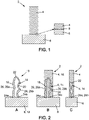
- the current methods of welding a blade 4 made of an aluminum-based alloy to a foot 6 made of a titanium-based alloy result in exclusively loading a connecting zone 8 between said foot 6 and the blade 4.
- This welding is very difficult or even impossible to achieve with conventional welding processes given the nature of the two materials to be brought into contact. Indeed, the melting temperatures of titanium and aluminum are too different and this welding then generates the formation of fragile intermetallic phases in the connection zone 8. Even if welding remains possible, the connection zone 8 between the blade 4 and the foot 6 forming a plane-plane interface, containing fragile intermetallic phases, risk of breaking because all of the forces between the blade 4 and the foot 6 are concentrated on the fragile connection zone 8.
- connection zone 8 This risk of rupture is all the more important as the speeds of rotation of the turbomachine are high.
- the problem remains similar if other assembly processes such as brazing or riveting are used. Indeed, in such situations a hole in the connection zone 8 generates a concentration of mechanical stresses in this connection zone 8 which can cause cracking.
- the protrusions make it possible to generate a large specific surface ensuring effective anchoring of the first part with the third part.
- the protrusions may include protrusions extending transversely inward from the general U-shape and/or protrusions extending transversely outward from the general U-shape.
- Said second part may include at least one internal air circulation circuit capable of receiving hot air coming from outside the blade.
- the internal air circulation circuit of the second part thus makes it possible to heat the blade and thus prevent the accretion of ice.
- the internal air circulation circuit may comprise air outlets opening onto an exterior surface of the third part. This internal air circulation circuit also makes it possible to modify the aerodynamics of the blade and to sample a circulating boundary layer in the vicinity of the first part as well as in the vicinity of the outer surface of the third part forming a trailing edge.
- This document relates to a blade 2 comprising a root 6 made of a titanium-based alloy compatible with the materials used for a disc (or shroud) carrying said roots 6 of blade 2.
- This compatibility makes it possible to envisage a direct assembly between the dawn 2 extending longitudinally and the disc (or the shell) by friction welding for example.
- Said blade 2 further comprises a blade 4 comprising an aluminum alloy.
- the figure 2 illustrates a schematic representation of a first embodiment of a turbine engine blade 2 according to this document. More specifically, the figure 2A illustrates a schematic representation of an assembly 10 comprising a first part 12 and a second part 14.
- the figure 2B is a schematic representation of a turbomachine blade 2 seen from the front and the Fig. 2C is a schematic representation of a turbomachine blade 2 seen from the side.
- the second part 14 comprises a general U-shape adapted to extend projecting from the first part 12 in the longitudinal direction over a longitudinal dimension of between 20 and 90% of the longitudinal dimension of the blade. This second part 14 is intended to form with a third part 16 the blade of the dawn.
- This second part 14 comprises a first branch 18 and a second branch 20 which are connected to each other by a top part 22.
- the first branch 18 and the second branch 20 each comprise an end 24a, 24b of a side opposite the crown part 22. These ends 24a, 24b of the first branch 18 and of the second branch 20 are each connected to the first part 12.
- One and/or the other of the first branch 18 and of the second branch 20 comprise protrusions 26.
- These protrusions 26 comprise protrusions extending transversely inside 26a of the general U-shape and/or protrusions extending transversely outwards 26b of the general U-shape
- These protrusions 26 form grip zones comprising a surface state such that the grip on the third part 16 is optimized.
- the first part 12 is intended to form the root 6 of the blade 2.
- the first part 12 may have a shape initially distinct from the final shape of the root 6 of the blade 2. This first part 12, being able to form a preform of the root , can thus be machined in order to match the final shape of the root 6 of blade 2 desired.
- the blade 2 comprises a first part 12, a second part 14 and a third part 16 similarly to the first embodiment.
- the second part 14 comprises an internal air circulation circuit 28.
- This internal air circulation circuit 28 comprises a first section 30 having one end 32 opening outside the first part 12, on the side opposite to the blade 4.
- This internal circulation circuit 28 further comprises a second section 34 passing inside the second part 14 having a general U-shape and a third section 36 continuously connected to the second section 34 and opening outside the first part on the side opposite the blade.
- the blade 2 comprises a first part 12, a second part 14 and a third part 16 similarly to the first embodiment.
- an internal air circulation circuit 28 begins in the first branch 18 at the end opposite the top part.
- This end opposite to the crown part 22 comprises a first zone 38 adjacent to the first part 12 and a second zone 40 emerging outside the blade 2.
- This second zone 40 can comprise a single zone emerging outside of the blade or a plurality of zones opening outside the blade over a dimension comprised between 0 and 80% of a longitudinal dimension of the third part.
- the second branch 20 of the second part 14 is free, that is to say not connected to the first part 12, and comprises air outlets 42 opening onto an outer surface of the third part 16.
- These air outlets air 42 can, for example, be three in number but this number of air outlets is not limiting and there can be a single air outlet or a plurality.
- a mold 44 is used to manufacture such a blade 2.
- Said blade 2 to be manufactured ultimately matches the geometry of the mold 44.
- the mold 44 comprises at least a first shell 46 and a second shell 48 which are arranged one against the other form said mold 44.
- the first shell 46 has a first internal face forming a first cavity 50.
- the second shell 48 has a second internal face forming a second cavity 52.
- the first cavity 50 and the second cavity 52 together form a cavity 58 in which the blade is intended to be formed.
- the first cavity 50 and the second cavity 52 each comprise a first zone 60a, 60b and a second zone 62a, 62b.
- the first zone 60a of the first cavity 50 delimits with a first zone 60b of the second cavity 52 a first space 64 of the cavity 58, which is intended to form the blade.
- the second zone 62a of the first cavity 50 delimits with the second zone 62b of the second cavity 52 a second space 66 of cavity 58 which is intended to receive the first part 12 of the blade 2.
- the first space 64 of the cavity 58 and the second space 66 of the cavity 58 together form the internal cavity 58 of the mold 44 intended to receive the second part 14 of the blade 2.
- the first shell 46 comprises a first internal channel 54 of which a first end opens at the level of the first part 64 of the cavity 58 and a second end opens outside of said mold 44.
- the second shell 48 comprises a second internal channel 56 of which a first end opens at the level of the second part 66 of the cavity 58 and a second end opens outside of said mold 44.
- the first space 64 of the cavity 58 delimits a zone into which is injected a liquid metal intended to form the third part of the blade.
- the second space 66 of the cavity 58 is, moreover, capable of receiving in particular the root of the blade, preferably manufactured by additive manufacturing.
- the first part 12 is arranged in the second space 66 of the cavity 58 and the second part 14 is arranged in the first space 64 of the cavity 58.
- An aluminum-based alloy is injected so as to form the third part 16 and to embed the second part 14, the second part then being surrounded by the third part.
- the second 14 and the third part 16 thus form the blade 4 of the blade 2.
- the second part 14 makes it possible to ensure attachment of the third part 16 to the second part 14, the latter therefore forming a means of attachment between the foot and the third part 16 intended to form the part of the blade 2 aluminum alloy.
- the shape of the second part 14 and in particular the protrusions make it possible to achieve a large specific surface ensuring effective anchoring of the second part 14 with the third part 16.
- the shape of the second part allows radial mechanical retention and the surface finish optimizes grip in a transverse direction by increasing the specific surface. This surface condition also makes it possible to compensate for shrinkage linked to solidification of the third part around the U. Due to its shape, the second part 14 can, moreover, make it possible to stiffen the blade when the blade is not sufficiently rigid. This second part 14 therefore forms, by virtue of its arrangement and its constitution, a means for adjusting the stiffness of the blade.
- the internal air circulation circuit 28 of the second part can make it possible to heat the blade and thus prevent the accretion of ice by circulation of air in the internal structure of the blade.
- This internal air circulation circuit 28 can also make it possible to modify the aerodynamics of the blade 4 and to sample a circulating boundary layer in the vicinity of the outer surface of the third part forming a trailing edge.
- the first part 12 is advantageously made of a titanium-based alloy having a melting temperature of between 1600 and 1700°C and the second is of an aluminum-based alloy having a melting temperature of between 500 and 600°C. This difference between the melting temperatures of aluminum and titanium makes it possible to limit the interactions between the third part 16 on the one hand, and the first part 12 and second part 14 on the other hand and thus to limit the formation of phases fragile.
- the first part 12 and the second part can be obtained by means of an additive manufacturing process. In this way, the second part 14 can have any shape suitable for attaching the third part 16 to the second part 14.
Landscapes
- Engineering & Computer Science (AREA)
- Mechanical Engineering (AREA)
- General Engineering & Computer Science (AREA)
- Manufacturing & Machinery (AREA)
- Chemical & Material Sciences (AREA)
- Composite Materials (AREA)
- Materials Engineering (AREA)
- Structures Of Non-Positive Displacement Pumps (AREA)
- Turbine Rotor Nozzle Sealing (AREA)
Abstract
Description
- Le présent document concerne un procédé de fabrication d'une aube pour turbomachine comportant un pied en alliage à base de titane relié à une pale à base d'aluminium.
- Une nouvelle architecture de turbomachine est recherchée afin de satisfaire les besoins de l'aviation. Cette nouvelle architecture nécessite une mise en œuvre de compresseurs capables de supporter de fortes vitesses de rotation. Ce changement d'architecture induit des contraintes supplémentaires ou nouvelles, qu'il est nécessaire de considérer dans la fabrication des aubes 2 rotoriques et statoriques de compresseurs.
Parmi celles-ci, la masse des aubages en rotation est notamment un défi. Classiquement, il est connu de fabriquer des aubes comprenant un pied et une pale, les aubes étant réalisées en titane afin d'assurer une certaine résistance mécanique à l'ensemble. Cependant, les aubages en alliage de titane imposent des efforts centrifuges importants, notamment sur le disque portant lesdites aubes, rendant la recherche de solutions matériaux à faible densité nécessaire.
Employer des alliages tels que de l'aluminium afin de réduire la densité de la pale n'est pas sans conséquence. Comme illustré enfigure 1 , les procédés actuels de soudure d'une pale 4 en alliage à base d'aluminium à un pied 6 en un alliage à base de titane conduisent à charger exclusivement une zone de liaison 8 entre ledit pied 6 et la pale 4. Cette soudure est très difficile voire impossible à réaliser avec des procédés de soudure conventionnels compte tenu de la nature des deux matériaux à mettre en contact. En effet, les températures de fusion du titane et de l'aluminium sont trop différentes et cette soudure génère alors la formation de phases intermétalliques fragiles dans la zone de liaison 8. Même si la soudure reste possible, la zone de liaison 8 entre la pale 4 et le pied 6 formant une interface plan-plan, contenant des phases intermétalliques fragiles, risque de rompre car l'intégralité des efforts entre la pale 4 et le pied 6 se concentre sur la zone de liaison 8 fragile. Ce risque de rupture est d'autant plus important que les vitesses de rotation de la turbomachine sont grandes.
La problématique reste similaire si on utilise d'autres procédés d'assemblage comme le brasage ou le rivetage. En effet, dans de telles situations un perçage dans la zone de liaison 8 engendre une concentration des contraintes mécaniques dans cette zone de liaison 8 qui peuvent engendrer des fissurations. - Le présent document concerne un procédé de fabrication d'une aube pour turbomachine comportant un pied relié à une pale s'étendant selon une direction longitudinale, le procédé comprenant les étapes:
- fournir un ensemble comprenant :
- ∘ un première partie destinée à former un pied de l'aube, cette première partie étant réalisée en un alliage à base de titane,
- ∘ une deuxième partie s'étendant en saillie selon la direction longitudinale depuis la première partie ;
- fournir un moule comprenant une première empreinte et une seconde empreinte délimitant ensemble une cavité dans laquelle l'aube est destinée à être formée, ladite cavité comprenant un premier espace destiné à former la pale et un second espace destiné à former le pied ;
- agencer la première partie dans le premier espace de la cavité et la deuxième partie dans le second espace de la cavité ;
- injecter un alliage à base d'aluminium, cet alliage formant une troisième partie dans laquelle est noyée la deuxième partie.
- Les excroissances permettent de générer une surface spécifique importante assurant un ancrage efficace de la première partie avec la troisième partie.
Les excroissances peuvent comporter des excroissances s'étendant transversalement vers l'intérieur de la forme générale en U et/ou des excroissances s'étendant transversalement vers l'extérieur de la forme générale en U.
Ladite deuxième partie peut comporter au moins un circuit interne de circulation d'air apte à recevoir de l'air chaud venant de l'extérieur de l'aube.
Le circuit interne de circulation d'air de la deuxième partie permet ainsi de réchauffer la pale et ainsi éviter l'accrétion de glace.
Le circuit interne de circulation d'air peut comprendre des sorties d'air débouchant sur une surface extérieure de la troisième partie.
Ce circuit interne de circulation d'air permet également de modifier l'aérodynamisme de la pale et de prélever une couche limite circulante au voisinage de la première partie ainsi qu'au voisinage de la surface extérieure de la troisième partie formant un bord de fuite. -
- [
Fig. 1 ] représente une représentation schématique d'une aube de turbomachine ; - [
Fig. 2 ] représente :- en
figure 2A une représentation schématique d'un premier mode de réalisation d'un ensemble comprenant une première partie et une deuxième partie selon l'invention ; - en
figure 2B une représentation schématique du premier mode de réalisation de l'aube de turbomachine vue de face selon l'invention ; - en
figure 2C une représentation schématique du premier mode de réalisation de l'aube de turbomachine vue de côté selon l'invention ;
- en
- [
Fig. 3 ] représente une représentation schématique d'un deuxième mode de réalisation d'une aube de turbomachine comportant un circuit de circulation d'air selon l'invention ; - [
Fig. 4 ] représente une représentation schématique d'un troisième mode de réalisation d'une aube de turbomachine comportant un circuit de circulation d'air selon l'invention ; - [
Fig. 5 ] représente une représentation schématique d'un moule selon l'invention ; - Le présent document concerne une aube 2 comprenant un pied 6 en un alliage à base de titane compatible avec les matériaux employés pour un disque (ou virole) portant lesdits pieds 6 d'aube 2. Cette compatibilité permet d'envisager un assemblage direct entre l'aube 2 s'étendant longitudinalement et le disque (ou la virole) par soudage par friction par exemple. Ladite aube 2 comporte, en outre, une pale 4 comprenant un alliage d'aluminium.
- La
figure 2 illustre une représentation schématique d'un premier mode de réalisation d'une aube 2 de turbomachine selon le présent document. Plus précisément, lafigure 2A illustre une représentation schématique d'un ensemble 10 comprenant une première partie 12 et une deuxième partie 14. Lafigure 2B est une représentation schématique d'une aube 2 de turbomachine vue de face et lafigure 2C est une représentation schématique d'une aube 2 de turbomachine vue de côté.
Comme illustré enfigure 2 , la deuxième partie 14 comprend une forme générale en U adaptée pour s'étendre en saillie depuis la première partie 12 selon la direction longitudinale sur une dimension longitudinale comprise entre 20 et 90% de la dimension longitudinale de l'aube. Cette deuxième partie 14 est destinée à former avec une troisième partie 16 la pale de l'aube. Cette deuxième partie 14 comporte une première branche 18 et une seconde branche 20 qui sont reliées l'une à l'autre par une partie de sommet 22. La première branche 18 et la seconde branche 20 comprennent chacune une extrémité 24a, 24b d'un côté opposé à la partie de sommet 22. Ces extrémités 24a, 24b de la première 18 branche et de la seconde 20 branche sont chacune reliées à la première partie 12. L'une et/ou l'autre de la première branche 18 et de la seconde 20 branche comprennent des excroissances 26. Ces excroissances 26 comprennent des excroissances s'étendant transversalement à l'intérieur 26a de la forme générale en U et/ou des excroissances s'étendant transversalement vers l'extérieur 26b de la forme générale en U. Ces excroissances 26 forment des zones d'accroche comprenant un état de surface tel que l'accroche à la troisième partie 16 est optimisée.
La première partie 12 est destinée à former le pied 6 de l'aube 2. La première partie 12 peut présenter une forme initialement distincte de la forme finale du pied 6 d'aube 2. Cette première partie 12, pouvant former une préforme du pied, peut ainsi être usinée afin d'épouser la forme finale du pied 6 d'aube 2 souhaitée. - Selon un deuxième mode de réalisation illustré en
figure 3 , l'aube 2 comporte une première partie 12, une deuxième partie 14 et une troisième partie 16 de façon similaire au premier mode de réalisation. Dans cette réalisation, la deuxième partie 14 comporte un circuit interne de circulation d'air 28. Ce circuit interne de circulation d'air 28 comporte une première section 30 ayant une extrémité 32 débouchant à l'extérieur de la première partie 12, du côté opposé à la pale 4. Ce circuit de circulation d'interne 28 comprend, en outre, une deuxième section 34 passant à l'intérieur de la deuxième partie 14 ayant une forme générale en U et une troisième section 36 reliée de façon continue à la deuxième section 34 et débouchant à l'extérieur de la première partie du côté opposé à la pale. - Selon un troisième mode de réalisation particulier illustré en
figure 4 , l'aube 2 comporte une première partie 12, une deuxième partie 14 et une troisième partie 16 de façon similaire au premier mode de réalisation. Dans ce troisième mode de réalisation, un circuit interne de circulation d'air 28 débute dans la première branche 18 à l'extrémité opposée à la partie de sommet. Cette extrémité opposée à la partie de sommet 22 comporte une première zone 38 adjacente à la première partie 12 et une seconde zone 40 débouchant à l'extérieur de l'aube 2. Cette seconde zone 40 peut comprendre une seule zone débouchant à l'extérieur de l'aube ou une pluralité de de zones débouchant à l'extérieur de l'aube sur une dimension comprise entre 0 et 80% d'une dimension longitudinale de la troisième partie. La seconde branche 20 de la deuxième partie 14 est libre, c'est-à-dire non reliée à la première partie 12, et comprend des sorties d'air 42 débouchant sur une surface extérieure de la troisième partie 16. Ces sorties d'air 42 peuvent, par exemple, être au nombre de trois mais ce nombre de sorties d'air n'est pas limitatif et il peut y avoir une seule sortie d'air ou une pluralité. - Comme illustré en
figure 5 , un moule 44 est utilisé afin de fabriquer une telle aube 2. Ladite aube 2 à fabriquer épouse in fine la géométrie du moule 44. Le moule 44 comprend au moins une première coque 46 et une seconde coque 48 qui agencées l'une contre l'autre forment ledit moule 44. La première coque 46 comporte une première face interne formant une première empreinte 50. La seconde coque 48 comporte une seconde face interne formant une seconde empreinte 52. Lorsque la première coque 46 et la seconde coque 48 sont assemblées l'une contre l'autre, la première empreinte 50 et la seconde empreinte 52 forment ensemble une cavité 58 dans laquelle l'aube est destinée à être formée.
La première empreinte 50 et la seconde empreinte 52 comprennent chacune une première zone 60a, 60b et une seconde zone 62a, 62b. La première zone 60a de la première empreinte 50 délimite avec une première zone 60b de la seconde empreinte 52 un premier espace 64 de la cavité 58, laquelle est destinée à former la pale. La seconde zone 62a de la première empreinte 50 délimite avec la seconde zone 62b de la seconde empreinte 52 un second espace 66 de cavité 58 lequel est destiné à recevoir la première partie 12 de l'aube 2. Le premier espace 64 de la cavité 58 et le second espace 66 de la cavité 58 forment ensemble la cavité interne 58 du moule 44 destinée à recevoir la deuxième partie 14 de l'aube 2.
La première coque 46 comporte un premier canal interne 54 dont une première extrémité débouche au niveau de la première partie 64 de la cavité 58 et une seconde extrémité débouche à l'extérieur dudit moule 44. La seconde coque 48 comporte un second canal interne 56 dont une première extrémité débouche au niveau de la seconde partie 66 de la cavité 58 et une seconde extrémité débouche à l'extérieur dudit moule 44.
Le premier espace 64 de la cavité 58 délimite une zone dans laquelle est injecté un métal liquide destiné à former la troisième partie de l'aube. Le second espace 66 de la cavité 58 est, en outre, apte à recevoir notamment le pied de l'aube fabriqué de préférence par fabrication additive. - Selon le présent document, la première partie 12 est agencée dans le second espace 66 de la cavité 58 et la deuxième partie 14 est agencée dans le premier espace 64 de la cavité 58. Un alliage à base d'aluminium est injecté de façon à former la troisième partie 16 et à noyer la deuxième partie 14, la deuxième partie étant alors entourée par la troisième partie. La deuxième 14 et la troisième partie 16 forment ainsi la pale 4 de l'aube 2.
On comprend que la deuxième partie 14 permet d'assurer un accrochage de la troisième partie 16 sur la deuxième partie 14, cette dernière formant donc un moyen d'accroche entre le pied et la troisième partie 16 destinée à former la partie de la pale 2 en alliage d'aluminium. En effet, la forme de la deuxième partie 14 et notamment les excroissances permettent de réaliser une surface spécifique importante assurant un ancrage efficace de la deuxième partie 14 avec la troisième partie 16. La forme de la deuxième partie permet un maintien mécanique radial et l'état de surface permet d'optimiser l'accroche dans un sens transverse en augmentant la surface spécifique. Cet état de surface permet, en outre, de compenser des retraits liés à une solidification de la troisième partie autour du U.
De par sa forme, la deuxième partie 14 peut, en outre, permettre de rigidifier la pale lorsque la pale n'est pas suffisamment rigide. Cette deuxième partie 14 forme donc, de par son agencement et sa constitution, un moyen d'ajustement de la raideur de la pale.
Le circuit interne de circulation d'air 28 de la deuxième partie peut permettre de réchauffer la pale et ainsi éviter l'accrétion de glace par circulation d'air dans la structure interne de la pale. Ce circuit interne de circulation d'air 28 peut également permettre de modifier l'aérodynamisme de la pale 4 et de prélever une couche limite circulante au voisinage de la surface extérieure de la troisième partie formant un bord de fuite.
La première partie 12 est avantageusement en un alliage à base de titane ayant une température de fusion comprise entre 1600 et 1700°C et la seconde est en un alliage à base d'aluminium ayant une température de fusion comprise entre 500 et 600 °C. Cette différence entre les températures de fusion de l'aluminium et du titane permet de limiter les interactions entre la troisième partie 16 d'une part, et la première partie 12 et deuxième partie 14 d'autre part et de limiter ainsi la formation de phases fragiles.
La première partie 12 et la deuxième partie peuvent être obtenues au moyen d'un procédé de fabrication additive. De cette manière, la deuxième partie 14 peut présenter toute forme adaptée à l'accrochage de la troisième partie 16 sur la deuxième partie 14.
La première partie est en un alliage à base de titane ayant une température de fusion comprise entre 1600 et 1700°C et la deuxième est en un alliage à base d'aluminium ayant une température de fusion comprise entre 500 et 600 °C. Cette différence entre les températures de fusion de l'aluminium et du titane permet de limiter les interactions entre la troisième partie d'une part, et la première partie et deuxième partie d'autre part et de limiter ainsi la formation de phases fragiles.
L'ensemble peut être réalisé en fabrication additive.
La deuxième partie peut comprendre une forme générale en U comportant une première branche et une seconde branche reliées par une partie de sommet.
De par sa forme, la deuxième partie permet de raidir la pale lorsque la pale n'est pas suffisamment raide. Cette deuxième partie comprend donc de par sa forme un moyen d'ajustement de la raideur de la pale.
La première branche et/ou la seconde branche peuvent comprendre des excroissances.
Claims (7)
- Procédé de fabrication d'une aube (2) pour turbomachine comportant un pied (6) relié à une pale (4) s'étendant selon une direction longitudinale, le procédé comprenant les étapes:- fournir un ensemble (10) comprenant :∘ un première partie (12) destinée à former un pied (6) de l'aube (2), cette première partie (12) étant réalisée en un alliage à base de titane,∘ une deuxième partie (14) s'étendant en saillie selon la direction longitudinale depuis la première partie (12) ;- fournir un moule comprenant une première empreinte (50) et une seconde empreinte (52) délimitant ensemble une cavité (58) dans laquelle l'aube est destinée à être formée, ladite cavité (58) comprenant un premier espace (64) destiné à former la pale et un second espace (66) destiné à former le pied (6) ;- agencer la première partie (12) dans le premier espace (64) de la cavité (58) et la deuxième partie (14) dans le second espace (66) de la cavité (58) ;- injecter un alliage à base d'aluminium, cet alliage formant une troisième partie (16) dans laquelle est noyée la deuxième partie (14).
- Procédé de fabrication d'une aube selon la revendication 1, dans lequel l'ensemble (10) est réalisé en fabrication additive.
- Procédé de fabrication d'une aube selon l'une des revendications précédentes, dans lequel la deuxième partie comprend une forme générale en U comportant une première branche (18) et une seconde branche (20) reliées par une partie de sommet (22).
- Procédé de fabrication d'une aube selon la revendication 3, dans lequel la première branche (18) et/ou la seconde branche (20) comprennent des excroissances (26).
- Procédé de fabrication d'une aube selon la revendication 4, dans lequel les excroissances (26) comporte des excroissances s'étendant transversalement vers l'intérieur (26a) de la forme générale en U et/ou des excroissances s'étendant transversalement vers l'extérieur (26b) de la forme générale en U.
- Procédé de fabrication d'une aube selon l'une des revendications précédentes, dans lequel ladite deuxième partie (14) comporte au moins un circuit interne de circulation d'air (28) apte à recevoir de l'air chaud venant de l'extérieur de l'aube (2).
- Procédé de fabrication d'une aube selon la revendication 6, dans lequel le circuit interne de circulation d'air (28) comprend des sorties d'air (42) débouchant sur une surface extérieure de la troisième partie (16).
Priority Applications (4)
| Application Number | Priority Date | Filing Date | Title |
|---|---|---|---|
| EP20306289.8A EP3991883A1 (fr) | 2020-10-27 | 2020-10-27 | Procédé de fabrication d'une aube pour turbomachine |
| PCT/EP2021/079460 WO2022090116A1 (fr) | 2020-10-27 | 2021-10-25 | Procédé de fabrication d'une aube pour turbomachine |
| US18/034,166 US12398645B2 (en) | 2020-10-27 | 2021-10-25 | Method for manufacturing a blade for a turbomachine |
| CN202180076842.3A CN116635177B (zh) | 2020-10-27 | 2021-10-25 | 制造用于涡轮发动机的叶片的方法 |
Applications Claiming Priority (1)
| Application Number | Priority Date | Filing Date | Title |
|---|---|---|---|
| EP20306289.8A EP3991883A1 (fr) | 2020-10-27 | 2020-10-27 | Procédé de fabrication d'une aube pour turbomachine |
Publications (1)
| Publication Number | Publication Date |
|---|---|
| EP3991883A1 true EP3991883A1 (fr) | 2022-05-04 |
Family
ID=73838992
Family Applications (1)
| Application Number | Title | Priority Date | Filing Date |
|---|---|---|---|
| EP20306289.8A Pending EP3991883A1 (fr) | 2020-10-27 | 2020-10-27 | Procédé de fabrication d'une aube pour turbomachine |
Country Status (4)
| Country | Link |
|---|---|
| US (1) | US12398645B2 (fr) |
| EP (1) | EP3991883A1 (fr) |
| CN (1) | CN116635177B (fr) |
| WO (1) | WO2022090116A1 (fr) |
Citations (3)
| Publication number | Priority date | Publication date | Assignee | Title |
|---|---|---|---|---|
| WO1997033009A1 (fr) * | 1996-03-07 | 1997-09-12 | Minnesota Mining And Manufacturing Company | Titane renforce a l'aide d'un composite matriciel a base d'aluminium |
| US20070274854A1 (en) * | 2006-05-23 | 2007-11-29 | General Electric Company | Method of making metallic composite foam components |
| FR3081370A1 (fr) * | 2018-05-22 | 2019-11-29 | Safran Aircraft Engines | Corps d'aube et aube en materiau composite ayant un renfort fibreux compose d'un tissage tridimensionnel et de fibres courtes et leur procede de fabrication |
Family Cites Families (10)
| Publication number | Priority date | Publication date | Assignee | Title |
|---|---|---|---|---|
| US5226469A (en) * | 1987-07-01 | 1993-07-13 | Kawasaki Jukogyo Kabushiki Kaisha | Composite structures and methods of manufacturing the same |
| DE19805175A1 (de) * | 1998-02-10 | 1999-08-19 | Daimler Chrysler Ag | Verfahren zum Verbinden von wenigstens zwei Bauteilen |
| US20150211372A1 (en) * | 2014-01-30 | 2015-07-30 | Solar Turbines Incorporated | Hot isostatic pressing to heal weld cracks |
| FR3023317B1 (fr) * | 2014-07-04 | 2016-08-05 | Snecma | Procede de fabrication d'une aube bi-composant pour moteur a turbine a gaz et aube obtenue par un tel procede |
| US9968991B2 (en) * | 2015-12-17 | 2018-05-15 | General Electric Company | Method and assembly for forming components having internal passages using a lattice structure |
| US10422228B2 (en) * | 2016-04-12 | 2019-09-24 | United Technologies Corporation | Manufacturing a monolithic component with discrete portions formed of different metals |
| US20180161857A1 (en) * | 2016-12-13 | 2018-06-14 | General Electric Company | Integrated casting core-shell structure for making cast components having thin root components |
| US20200109635A1 (en) * | 2018-10-05 | 2020-04-09 | United Technologies Corporation | Composite cast porous metal turbine component |
| FR3105035B1 (fr) * | 2019-12-23 | 2021-12-10 | Safran Helicopter Engines | Procédé de fabrication d’aube de turbomachine et aube de turbomachine |
| US11454118B2 (en) * | 2020-09-04 | 2022-09-27 | General Electric Company | Gas turbine engine rotor blade having a root section with composite and metallic portions |
-
2020
- 2020-10-27 EP EP20306289.8A patent/EP3991883A1/fr active Pending
-
2021
- 2021-10-25 WO PCT/EP2021/079460 patent/WO2022090116A1/fr not_active Ceased
- 2021-10-25 CN CN202180076842.3A patent/CN116635177B/zh active Active
- 2021-10-25 US US18/034,166 patent/US12398645B2/en active Active
Patent Citations (3)
| Publication number | Priority date | Publication date | Assignee | Title |
|---|---|---|---|---|
| WO1997033009A1 (fr) * | 1996-03-07 | 1997-09-12 | Minnesota Mining And Manufacturing Company | Titane renforce a l'aide d'un composite matriciel a base d'aluminium |
| US20070274854A1 (en) * | 2006-05-23 | 2007-11-29 | General Electric Company | Method of making metallic composite foam components |
| FR3081370A1 (fr) * | 2018-05-22 | 2019-11-29 | Safran Aircraft Engines | Corps d'aube et aube en materiau composite ayant un renfort fibreux compose d'un tissage tridimensionnel et de fibres courtes et leur procede de fabrication |
Also Published As
| Publication number | Publication date |
|---|---|
| CN116635177A (zh) | 2023-08-22 |
| US12398645B2 (en) | 2025-08-26 |
| US20230407751A1 (en) | 2023-12-21 |
| WO2022090116A1 (fr) | 2022-05-05 |
| CN116635177B (zh) | 2026-01-06 |
Similar Documents
| Publication | Publication Date | Title |
|---|---|---|
| EP2805020B2 (fr) | Aube mobile de turbomachine et turbomachine correspondante | |
| EP2951397B1 (fr) | Aube de rotor de turbomachine | |
| CA2889751C (fr) | Moyeu de carter d'echappement pour une turbomachine | |
| EP1481756B1 (fr) | Procédé de fabrication d'une aube creuse pour turbomachine | |
| FR2941487A1 (fr) | Aube de turbomachine en materiau composite a pied renforce | |
| EP3429784B1 (fr) | Procede de fabrication d'un anneau de turbine pour turbomachine | |
| FR2929149A1 (fr) | Procede de fabrication d'une aube creuse | |
| EP3218141A1 (fr) | Procédé de soudage par friction avec rechargement d'une pale sur une aube de turbomachine | |
| FR3098246A1 (fr) | Turbine de turbomachine à distributeur en CMC avec reprise d’effort | |
| EP4081360B1 (fr) | Procede de fabrication d'aube de turbomachine et aube de turbomachine | |
| WO2022090116A1 (fr) | Procédé de fabrication d'une aube pour turbomachine | |
| EP3983650B1 (fr) | Turbine de turbomachine à distributeur en cmc avec reprise d'effort | |
| FR2855440A1 (fr) | Procede de fabrication d'une aube creuse pour turbomachine. | |
| EP4115056A1 (fr) | Plateforme composite pour une soufflante de turbomachine d'aeronef | |
| EP4251855B1 (fr) | Procédé et dispositif de fabrication d'un disque de turbomachine bi-matière et disque obtenu par ce procédé | |
| EP3683450B1 (fr) | Ensemble rotatif de turbomachine | |
| EP4363697A1 (fr) | Aube de turbomachine equipee d'un circuit de refroidissement et procede de fabrication a cire perdue d'une telle aube | |
| FR3127144A1 (fr) | Procédé de fabrication d’une pièce aéronautique bi-matériaux | |
| EP3847340B1 (fr) | Aube mobile | |
| EP3942157B1 (fr) | Aube de turbomachine equipee d'un circuit de refroidissement et procede de fabrication a cire perdue d'une telle aube | |
| EP4076836A1 (fr) | Solution de fabrication d'un disque aubage monobloc | |
| FR3137006A1 (fr) | Procede de fabrication d’une pluralite d’aubes de turbomachine | |
| FR3127985A1 (fr) | Clinquant pour diminuer les contraintes dans un col de pied d’aube de turbine | |
| FR3106849A1 (fr) | Procédé de formation d’une aube de turbine, et aube associée. | |
| EP3991882A1 (fr) | Procédé de fabrication d'une aube pour turbomachine |
Legal Events
| Date | Code | Title | Description |
|---|---|---|---|
| PUAI | Public reference made under article 153(3) epc to a published international application that has entered the european phase |
Free format text: ORIGINAL CODE: 0009012 |
|
| STAA | Information on the status of an ep patent application or granted ep patent |
Free format text: STATUS: THE APPLICATION HAS BEEN PUBLISHED |
|
| AK | Designated contracting states |
Kind code of ref document: A1 Designated state(s): AL AT BE BG CH CY CZ DE DK EE ES FI FR GB GR HR HU IE IS IT LI LT LU LV MC MK MT NL NO PL PT RO RS SE SI SK SM TR |
|
| STAA | Information on the status of an ep patent application or granted ep patent |
Free format text: STATUS: REQUEST FOR EXAMINATION WAS MADE |
|
| 17P | Request for examination filed |
Effective date: 20221103 |
|
| RBV | Designated contracting states (corrected) |
Designated state(s): AL AT BE BG CH CY CZ DE DK EE ES FI FR GB GR HR HU IE IS IT LI LT LU LV MC MK MT NL NO PL PT RO RS SE SI SK SM TR |