EP3991873A1 - Flow path structure, check valve comprising same, and method for producing check valve - Google Patents
Flow path structure, check valve comprising same, and method for producing check valve Download PDFInfo
- Publication number
- EP3991873A1 EP3991873A1 EP20831089.6A EP20831089A EP3991873A1 EP 3991873 A1 EP3991873 A1 EP 3991873A1 EP 20831089 A EP20831089 A EP 20831089A EP 3991873 A1 EP3991873 A1 EP 3991873A1
- Authority
- EP
- European Patent Office
- Prior art keywords
- retaining ring
- check valve
- diameter
- flow path
- main body
- Prior art date
- Legal status (The legal status is an assumption and is not a legal conclusion. Google has not performed a legal analysis and makes no representation as to the accuracy of the status listed.)
- Withdrawn
Links
Images




Classifications
-
- F—MECHANICAL ENGINEERING; LIGHTING; HEATING; WEAPONS; BLASTING
- F16—ENGINEERING ELEMENTS AND UNITS; GENERAL MEASURES FOR PRODUCING AND MAINTAINING EFFECTIVE FUNCTIONING OF MACHINES OR INSTALLATIONS; THERMAL INSULATION IN GENERAL
- F16K—VALVES; TAPS; COCKS; ACTUATING-FLOATS; DEVICES FOR VENTING OR AERATING
- F16K15/00—Check valves
- F16K15/02—Check valves with guided rigid valve members
-
- B—PERFORMING OPERATIONS; TRANSPORTING
- B23—MACHINE TOOLS; METAL-WORKING NOT OTHERWISE PROVIDED FOR
- B23P—METAL-WORKING NOT OTHERWISE PROVIDED FOR; COMBINED OPERATIONS; UNIVERSAL MACHINE TOOLS
- B23P15/00—Making specific metal objects by operations not covered by a single other subclass or a group in this subclass
- B23P15/001—Making specific metal objects by operations not covered by a single other subclass or a group in this subclass valves or valve housings
-
- B—PERFORMING OPERATIONS; TRANSPORTING
- B21—MECHANICAL METAL-WORKING WITHOUT ESSENTIALLY REMOVING MATERIAL; PUNCHING METAL
- B21F—WORKING OR PROCESSING OF METAL WIRE
- B21F11/00—Cutting wire
-
- B—PERFORMING OPERATIONS; TRANSPORTING
- B21—MECHANICAL METAL-WORKING WITHOUT ESSENTIALLY REMOVING MATERIAL; PUNCHING METAL
- B21F—WORKING OR PROCESSING OF METAL WIRE
- B21F3/00—Coiling wire into particular forms
- B21F3/02—Coiling wire into particular forms helically
- B21F3/06—Coiling wire into particular forms helically internally on a hollow form
-
- B—PERFORMING OPERATIONS; TRANSPORTING
- B21—MECHANICAL METAL-WORKING WITHOUT ESSENTIALLY REMOVING MATERIAL; PUNCHING METAL
- B21F—WORKING OR PROCESSING OF METAL WIRE
- B21F37/00—Manufacture of rings from wire
- B21F37/02—Manufacture of rings from wire of resilient rings, e.g. key-rings
-
- B—PERFORMING OPERATIONS; TRANSPORTING
- B23—MACHINE TOOLS; METAL-WORKING NOT OTHERWISE PROVIDED FOR
- B23P—METAL-WORKING NOT OTHERWISE PROVIDED FOR; COMBINED OPERATIONS; UNIVERSAL MACHINE TOOLS
- B23P19/00—Machines for simply fitting together or separating metal parts or objects, or metal and non-metal parts, whether or not involving some deformation; Tools or devices therefor so far as not provided for in other classes
- B23P19/02—Machines for simply fitting together or separating metal parts or objects, or metal and non-metal parts, whether or not involving some deformation; Tools or devices therefor so far as not provided for in other classes for connecting objects by press fit or for detaching same
-
- F—MECHANICAL ENGINEERING; LIGHTING; HEATING; WEAPONS; BLASTING
- F16—ENGINEERING ELEMENTS AND UNITS; GENERAL MEASURES FOR PRODUCING AND MAINTAINING EFFECTIVE FUNCTIONING OF MACHINES OR INSTALLATIONS; THERMAL INSULATION IN GENERAL
- F16K—VALVES; TAPS; COCKS; ACTUATING-FLOATS; DEVICES FOR VENTING OR AERATING
- F16K1/00—Lift valves or globe valves, i.e. cut-off apparatus with closure members having at least a component of their opening and closing motion perpendicular to the closing faces
- F16K1/32—Details
-
- F—MECHANICAL ENGINEERING; LIGHTING; HEATING; WEAPONS; BLASTING
- F16—ENGINEERING ELEMENTS AND UNITS; GENERAL MEASURES FOR PRODUCING AND MAINTAINING EFFECTIVE FUNCTIONING OF MACHINES OR INSTALLATIONS; THERMAL INSULATION IN GENERAL
- F16K—VALVES; TAPS; COCKS; ACTUATING-FLOATS; DEVICES FOR VENTING OR AERATING
- F16K15/00—Check valves
- F16K15/02—Check valves with guided rigid valve members
- F16K15/025—Check valves with guided rigid valve members the valve being loaded by a spring
- F16K15/026—Check valves with guided rigid valve members the valve being loaded by a spring the valve member being a movable body around which the medium flows when the valve is open
-
- F—MECHANICAL ENGINEERING; LIGHTING; HEATING; WEAPONS; BLASTING
- F16—ENGINEERING ELEMENTS AND UNITS; GENERAL MEASURES FOR PRODUCING AND MAINTAINING EFFECTIVE FUNCTIONING OF MACHINES OR INSTALLATIONS; THERMAL INSULATION IN GENERAL
- F16K—VALVES; TAPS; COCKS; ACTUATING-FLOATS; DEVICES FOR VENTING OR AERATING
- F16K15/00—Check valves
- F16K15/02—Check valves with guided rigid valve members
- F16K15/06—Check valves with guided rigid valve members with guided stems
- F16K15/063—Check valves with guided rigid valve members with guided stems the valve being loaded by a spring
-
- F—MECHANICAL ENGINEERING; LIGHTING; HEATING; WEAPONS; BLASTING
- F16—ENGINEERING ELEMENTS AND UNITS; GENERAL MEASURES FOR PRODUCING AND MAINTAINING EFFECTIVE FUNCTIONING OF MACHINES OR INSTALLATIONS; THERMAL INSULATION IN GENERAL
- F16K—VALVES; TAPS; COCKS; ACTUATING-FLOATS; DEVICES FOR VENTING OR AERATING
- F16K15/00—Check valves
- F16K15/02—Check valves with guided rigid valve members
- F16K15/06—Check valves with guided rigid valve members with guided stems
- F16K15/067—Check valves with guided rigid valve members with guided stems stem guided at two or more points
-
- F—MECHANICAL ENGINEERING; LIGHTING; HEATING; WEAPONS; BLASTING
- F16—ENGINEERING ELEMENTS AND UNITS; GENERAL MEASURES FOR PRODUCING AND MAINTAINING EFFECTIVE FUNCTIONING OF MACHINES OR INSTALLATIONS; THERMAL INSULATION IN GENERAL
- F16K—VALVES; TAPS; COCKS; ACTUATING-FLOATS; DEVICES FOR VENTING OR AERATING
- F16K27/00—Construction of housing; Use of materials therefor
- F16K27/02—Construction of housing; Use of materials therefor of lift valves
- F16K27/0209—Check valves or pivoted valves
-
- F—MECHANICAL ENGINEERING; LIGHTING; HEATING; WEAPONS; BLASTING
- F16—ENGINEERING ELEMENTS AND UNITS; GENERAL MEASURES FOR PRODUCING AND MAINTAINING EFFECTIVE FUNCTIONING OF MACHINES OR INSTALLATIONS; THERMAL INSULATION IN GENERAL
- F16B—DEVICES FOR FASTENING OR SECURING CONSTRUCTIONAL ELEMENTS OR MACHINE PARTS TOGETHER, e.g. NAILS, BOLTS, CIRCLIPS, CLAMPS, CLIPS OR WEDGES; JOINTS OR JOINTING
- F16B21/00—Means for preventing relative axial movement of a pin, spigot, shaft or the like and a member surrounding it; Stud-and-socket releasable fastenings
- F16B21/10—Means for preventing relative axial movement of a pin, spigot, shaft or the like and a member surrounding it; Stud-and-socket releasable fastenings by separate parts
- F16B21/16—Means for preventing relative axial movement of a pin, spigot, shaft or the like and a member surrounding it; Stud-and-socket releasable fastenings by separate parts with grooves or notches in the pin or shaft
- F16B21/18—Means for preventing relative axial movement of a pin, spigot, shaft or the like and a member surrounding it; Stud-and-socket releasable fastenings by separate parts with grooves or notches in the pin or shaft with circlips or like resilient retaining devices, i.e. resilient in the plane of the ring or the like; Details
- F16B21/183—Means for preventing relative axial movement of a pin, spigot, shaft or the like and a member surrounding it; Stud-and-socket releasable fastenings by separate parts with grooves or notches in the pin or shaft with circlips or like resilient retaining devices, i.e. resilient in the plane of the ring or the like; Details internal, i.e. with spreading action
Definitions
- the present invention relates to a flow path structure, a check valve comprising the same, and a manufacturing method of the check valve.
- check valves are used to control the flow direction of the refrigerant (fluid).
- Patent Document 1 discloses a three-way port check valve including a valve main body having a first inlet disposed on a common axis, a second inlet, a cylinder portion connecting them, and an outlet perpendicular to the cylinder portion.
- the three-way port check valve of Patent Document 1 includes a valve element slidable in the cylinder, and a stopper having an orifice provided in the vicinity of the second inlet. Accordingly, when the supply of the fluid from the second inlet side is interrupted and switched to the supply from the first inlet side, the valve element slides in the cylinder portion and hits the stopper due to the inflow pressure, and the tapered portion functions to seal the orifice.
- the fluid flowing in from the second inlet passes through the flow path formed between the orifice, the cylinder, and the valve element, and flows to the outlet side.
- Patent Document 1 Japanese Unexamined Patent Application Publication No. H09-133235 A
- the stopper of Patent Document 1 is attached to the valve element by a snap ring fitted in a fitting groove formed in the vicinity of the second inlet.
- Typical snap rings are provided with holes at both end portions of a C-shaped plate material into which tools such as snap ring pliers can be inserted for ease of mounting. Accordingly, both end portions of the snap ring have a shape that protrudes toward the inner diameter side, but when the snap ring is attached to the fitting groove, both end portions often protrude into the flow path.
- the present invention has been made in view of the above problems, and has an object to provide a flow path structure, a check valve comprising the same, and a method for producing a check valve in which it is possible to ensure smooth flow of a fluid while reducing cost.
- the flow path structure comprises a hollow main body; and a retaining ring formed by processing a linear steel material into a C-shape, wherein: an annular fitting groove into which the retaining ring is fitted is provided inside of the main body, and a fluid flows inside the retaining ring fitted in the fitting groove.
- a “C-shape” refers to a shape in which the number of turns of a spiral shape is more than 0.5 and is less than 1, or a shape in which the angle formed by two straight lines connecting the center of the shape and both ends is more than 180 degrees and is less than 360 degrees.
- the C-shaped member when the C-shaped member is placed on a flat surface, in the case that both ends are offset in the height direction, the C-shaped member is considered to be a part of a spiral shape.
- the "linear steel member” for example, hard steel wire, piano wire, stainless steel wire, or the like may be used, but the present invention is not limited thereto.
- FIG. 1 is an axial cross-sectional view of the check valve 1 according to the present embodiment.
- FIG. 2 is an assembly perspective view of the check valve 1 illustrated in a state in which the valve main body 2 is split in half along the axis.
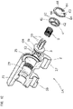
- FIG. 3 is an exploded perspective view of the check valve 1 illustrated in a state in which the valve main body 2 is split in half along the axis.
- FIG. 4 is a side view of the check valve 1 from the direction of the arrow A in FIG. 1 .
- L is set as the axis of the fluid passage of the check valve 1.
- the check valve 1 includes a hollow valve main body (also referred to as a main body) 2 having a refrigerant flow path (also referred to as a fluid passage) through which a refrigerant passes, a valve element 3 arranged in the fluid passage of the valve main body 2, a washer 4 attached to the valve main body 2, a coil spring 5 for biasing the valve element 3 with respect to the washer 4, and a retaining ring 6 for fixing the washer 4 to the valve main body 2.
- the check valve 1 is connected to a joint to which, for example, a refrigerant pipe connected to an evaporator and a compressor (not illustrated in the figure) is connected, whereby a closed refrigeration cycle is formed.
- the left side of the check valve 1 is considered to be the inlet side of the refrigerant, and the right side is considered to be the outlet side of the refrigerant.
- the valve main body 2 provided with the flow path structure has a substantially cylindrical first connecting portion 21, a first intermediate passage 22, a central passage 23, a substantially cylindrical second intermediate passage 24, and a substantially cylindrical second connecting portion (a large-diameter cylindrical portion) 25 starting from the inlet side of FIG. 1 along the axis L.
- Pipes (not illustrated in the figure) can be connected to the first connecting portion 21 and the second connecting portion 25, respectively.
- the first intermediate passage 22 connecting the first connecting portion 21 and the central passage 23 is formed by connecting a tapered tubular portion 221, a guide tubular portion 222 having a diameter smaller than that of the first connecting portion 21, and a valve seat 223 with a tapered diameter expanding toward the central passage 23 side.
- the second intermediate passage 24 connecting the central passage 23 and the second connecting portion 25 is formed by connecting a first linking tubular portion 241, an annular washer attachment portion 242, an annular retaining ring attachment groove (fitting groove) 243, and a second linking tubular portion 244.
- the inner diameter of the washer attachment portion 242 is larger than the inner diameter of the first linking tubular portion 242, and the inner diameter of the retaining ring attachment groove 243 is larger than the inner diameter of the washer attachment portion 242.
- the inner diameter of the second linking tubular portion 244 is smaller than the inner diameter of the retaining ring attachment groove 243 and larger than the inner diameter of the washer attachment portion 242.
- the inner diameter of the second connecting portion 25 is larger than the inner diameter of the retaining ring attachment groove 243 and the inner diameter of the second linking tubular portion 244. It should be noted that the size relationships of the inner diameters of each portion are not limited to the above-mentioned examples. For example, in the case that the inner diameter of the washer attachment portion 242 is smaller than the inner diameter of the retaining ring attachment groove 243, and the inner diameter of the retaining ring attachment groove 243 is larger than the inner diameter of the second linking tubular portion 244, the inner diameter of the second connecting portion 25 may be less than or equal to the inner diameter of the retaining ring attachment groove 243, and the inner diameter of the second connecting portion 25 may be the same as the inner diameter of the washer attachment portion 242.
- valve main body 2 has a first arm portion 26 extending radially outward from the first connecting portion 21, and a second arm portion 27 extending radially outward from the second connecting portion 25.
- the first arm portion 26 is formed with a screw hole 261 for screwing a bolt (not illustrated in the figure) for fixing a pipe connected to the first connecting portion 21, and the second arm portion 27 is formed with a screw hole 271 for screwing a bolt (not illustrated in the figure) for fixing a pipe connected to the second connecting portion 25.
- the valve element 3 is formed by connecting a disk portion 31, three leg portions 32 extending from the disk portion 31 along the axis L ( FIG. 1 ) toward the first connecting portion 21 side, and three leg portions 33 extending from the disk portion 31 along the axis L toward the second connecting portion 25 side.
- the interval between adjacent leg portions 32 is wider than the interval between the adjacent leg portions 33, and the length of the leg portions 32 is shorter than the length of the leg portions 33.
- the space between the adjacent leg portions 32 becomes the flow path through which the refrigerant passes.
- each leg portion 32 is a part of the same cylindrical surface, and the outer diameter of this same cylindrical surface substantially coincides with the inner diameter of the guide tubular portion 222. Accordingly, when the valve element 3 is installed on the valve main body 2 as illustrated in FIG. 1 and FIG. 2 , the valve element 3 is guided in the axis L direction by means of the leg portions 32 sliding in the guide tubular portion 222.
- a seal groove 311 is formed between the disk portion 31 and the leg portions 32 as illustrated by the dotted line in FIG. 1 .
- An O-ring OR is arranged in the seal groove 311.
- the washer 4 has an annular portion 41 and a plurality (here, three) column portions 42 extending from the annular portion 41 toward the center of the washer 4 at equal angles. The inner ends of the column portions 42 are joined to each other. The outer diameter of the washer 4 substantially matches the inner diameter of the washer attachment portion 242.
- one end of the coil spring 5 arranged around the leg portion 33 of the valve element 3 comes into contact with the end surface of the disk portion 31, and the other end of the coil spring 5 is supported by the column portion 42 of the washer 4.
- the coil spring 5 biases the valve element 3 toward the first connecting portion 21 side.
- the valve element 3 moves along the axis L in the valve main body 2 in accordance with the refrigerant pressure, and has a function of allowing or blocking the passage of the refrigerant flowing in from the first connecting portion 21 side.
- FIG. 5 is a diagram illustrating a state in which the retaining ring 6 is placed on a flat surface PL.
- the retaining ring 6 is a part of a linear steel material (or plate material) wound in a spiral shape, and has, for example, a uniform circular cross-sectional shape. Accordingly, as illustrated in FIG. 5 , when the retaining ring 6 is placed on the flat surface PL, in a state in which one end 61 is placed on the flat surface PL, the other end 62 is in a state suspended from the flat surface PL.
- one end 61 and the other end 62 are separated by a distance ⁇ along the height direction from the flat surface PL, and are also separated in the circumferential direction.
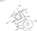
- FIG. 6 is a perspective view illustrating an example of a manufacturing device of the retaining ring 6.
- a guide 101, a bending die 102 for molding the linear steel material W into a coil shape having a predetermined curvature, a core metal 103 having a substantially semi-conical shape, and a pitch tool (not illustrated in the figure) that presses the linear steel material W that has been molded into a coil shape to form a predetermined pitch are installed so that they can move forward and backward with respect to the center of the coil.
- a rotating shaft 104 provided with a cutting blade 105 is rotatably arranged adjacent to the core metal 103.
- the linear steel material W fed by the feed roller is formed into a coil shape (a spiral shape) by passing through the guide 101, the core metal 103, the bending die 102 and the pitch tool.
- the cutting blade 105 comes into contact with the linear steel material W from the outer diameter direction, and cuts the linear steel material W in cooperation with the core metal 103.
- the retaining ring 6 illustrated in FIG. 5 is formed. While continuously supplying the linear steel material W, each time the cutting blade 105 is intermittently rotationally moved, retaining rings 6 are continuously formed.
- a retaining ring 6 can also be formed by forming a multi-wind coil with a spiral shape and then cutting the coil at predetermined angles. According to the molding method described above, the retaining ring 6 can be manufactured at low cost.
- FIG. 1 and FIG. 2 it is assumed that pipes are connected to the first connecting portion 21 and the second connecting portion 25, respectively.
- the refrigerant pressure of the first connecting portion 21 side is lower than the pressure obtained by applying a predetermined pressure (corresponding to the biasing force of the coil spring 5) to the refrigerant pressure of the second connecting portion 25 side
- the O-ring OR of the valve element 3 becomes seated on the valve seat 223 of the valve main body 2, which prevents the refrigerant from passing through the check valve 1, and the refrigerant does not flow out from the second connecting portion 25 side.
- the valve main body 3 moves in the valve opening direction (to the right in FIG. 1 ), the O-ring OR separates from the valve seat 223, and the refrigerant is allowed to pass from the first connecting portion 21 side to the second connecting portion 25 side through the inside of the retaining ring 6.
- a first assembly jig (a hollow cylindrical member) 110 and a second assembly jig 120 are prepared.
- the first assembly jig 110 has a substantially hollow cylindrical shape. More specifically, the first assembly jig 110 is formed by continuously connecting a thin-walled cylindrical portion 111 and a thick-walled cylindrical portion 112, and a step 113 is formed at the boundary of the cylindrical portion.
- the length of the thin-walled cylindrical portion 111 is B, the inner diameter thereof is C, and the outer diameter thereof is D.
- the inner circumference of the thick-walled cylindrical portion 112 has a tapered cylindrical shape in which the diameter gradually increases as the distance from the thin-walled cylindrical portion 111 increases, where the minimum inner diameter thereof is C, and the maximum inner diameter thereof is E.
- the second cylindrical assembly jig 120 includes a flange portion 121, a large cylindrical portion (an assembly jig) 122 protruding from one surface of the flange portion 121, and a small cylindrical portion (a small diameter assembly jig) 123 protruding from another surface of the flange portion 121.
- the outer diameter F of the large cylindrical portion 122 is larger than the outer diameter G of the small cylindrical portion 123.
- the length of the large cylindrical portion 122 is shorter than the length of the small cylindrical portion 123.
- a recessed portion 124 is formed in the center of the end surface of the small cylindrical portion 123.
- the distance from the end surface 251 of the second connecting portion 25 side of the valve main body 2 to the boundary between the second linking tubular portion 244 and the retaining ring attachment groove 243 is H
- the inner diameter of the second linking tubular portion 244 is I
- the outer diameter of the washer 4 is J.
- the inner diameter of the retaining ring 6 in a free state is K, and the outer diameter thereof is M.
- each part can be assembled using gravity.
- the valve element 3 equipped with the O-ring OR, and the coil spring 5 are inserted into the valve main body 2. Subsequently, the column portions 42 of the washer 4 are inserted between each of the leg portions 33 of the valve element 3, and the washer 4 is arranged at the upper end of the coil spring 5. In this state, the washer 4 is biased upward by the coil spring 5 and does not reach the washer attachment portion 242.
- the thin-walled cylindrical portion 111 of the first assembly jig 110 is inserted into the second linking tubular portion 244 through the second connecting portion 25. Since the inner diameter I of the second linking tubular portion 244 is larger than the outer diameter D of the thin-walled cylindrical portion 111 of the first assembly jig 110, the thin-walled cylindrical portion 111 is allowed to be inserted.
- the first assembly jig 110 is inserted into the valve main body 2 until the step 113 of the first assembly jig 110 comes into contact with the end surface 251 of the valve main body 2.
- the distance H from the end surface 251 of the second connection portion 25 side to the boundary between the second linking tubular portion 244 and the retaining ring attachment groove 243 and the length B of the thin-walled cylindrical portion 111 are substantially equal to each other, when the step 113 comes into contact with the end surface 251, the tip of the thin-walled cylindrical portion 111 is located at the boundary between the second linking tubular portion 244 and the retaining ring attachment groove 243 (see FIG. 8 ).
- the retaining ring 6 is inserted from the inner circumferential large-diameter end side of the thick-walled cylindrical portion 112 of the first assembly jig 110, and further, the retaining ring 6 is driven further by using the large cylindrical portion 122 of the second assembly jig 120.
- the retaining ring 6 can be inserted into the thick-walled cylindrical portion 112 without applying any external force to the retaining ring 6.
- the outer diameter F of the large cylindrical portion 122 of the second assembly jig 120 is smaller than the maximum inner diameter E of the thick-walled cylindrical portion 112, the large cylindrical portion 122 can be smoothly inserted into the thick-walled cylindrical portion 112.
- the retaining ring 6 in a free state is smaller than the outer diameter F of the large cylindrical portion 122, the retaining ring 6 can be pushed in without the large cylindrical portion 122 passing through the retaining ring 6.
- the diameter of the retaining ring 6 gradually decreases as it is pushed along the tapered inner circumferential surface of the thick-walled cylindrical portion 112.
- the retaining ring 6 When the flange portion 121 of the second assembly jig 120 comes into contact with the end surface 114 of the thick-walled cylindrical portion 112, the retaining ring 6 enters to about 1/3 of the length of the thick-walled cylindrical portion 112. At this time, the inner diameter of the retaining ring 6 is reduced while being elastically deformed by being pressed from the tapered inner circumferential surface of the thick-walled cylindrical portion 112, such that it becomes smaller than the outer diameter G of the small cylindrical portion 123 of the second assembly jig 120.
- the second assembly jig 120 is pulled out once and inverted, and then, as illustrated in FIG. 9 , the small cylindrical portion 123 is inserted into the tapered inner circumferential surface of the thick-walled cylindrical portion 112, pressed against the retaining ring 6, and further driven to pass through the inner circumferential surface of the thin-walled cylindrical portion 111.
- the leg portions 33 of the valve element 3 protrude into the second connecting portion 25, but since the recessed portion 124 is formed at the tip of the small cylindrical portions 123, interference between the small cylindrical portion 123 and the leg portions 33 can be avoided.
- the reason why the second assembly jig 120 is inverted and the retaining ring 6 is pressed in two steps is because the amount of diameter reduction of the retaining ring 6 when the retaining ring 6 is displaced along the tapered inner circumferential surface is relatively large. That is, the small cylindrical portion 123 cannot be pressed because it slips through the inside of the retaining ring 6 prior to the diameter reduction on the inner circumferential large diameter end side, and the large cylindrical portion 122 comes into contact with the inner circumference of the first assembly jig 110 on the small diameter end side such that the retaining ring 6 cannot be pressed. It should be noted that after pulling out the second assembly jig 120, the retaining ring 6 may be pressed by using another jig without inverting it.
- the retaining ring 6 is manufactured by a simple process of cutting a linear steel material (or plate material), the cut surfaces of one end 61 and the other end 62 are rough, and there is a high likelihood that burrs and the like may remain. Accordingly, if the retaining ring 6 were assembled to the valve main body 2 as it is, the inner circumferential surface of the valve main body 2 may be damaged by the cut end of the retaining ring 6.
- the thin-walled cylindrical portion 111 of the first assembly jig 110 by inserting the thin-walled cylindrical portion 111 of the first assembly jig 110 into the valve main body 2, the thin-walled cylindrical portion 111 protects the second connecting portion 25 or the like, and it is possible to prevent the inner circumferential surface of the valve main body 2 from being damaged by the cut end of the retaining ring 6.
- the retaining ring 6 that has passed through the thin-walled cylindrical portion 111 by means of the small cylindrical portion 123 of the second assembly jig 120 is pushed out from the end portion thereof (the inner circumferential small diameter end) to the outside of the first assembly jig 110.
- the retaining ring 6 is released from its compressed state, recovers from the elastic deformation, expands in diameter, and fits into the retaining ring attachment groove 243 adjacent to the thin-walled cylindrical portion 111.
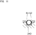
- both ends 61 and 62 which are separated by a distance ⁇ ( FIG. 6 ) in a free state, press the walls on both sides of the retaining ring attachment groove 243 in the axial direction by elastic deformation, thereby exerting a retaining effect.
- the retaining ring 6 pushed out by the second assembly jig 120 comes into contact with the washer 4 located below and pushes the washer 4 to the washer attachment portion 242. Since the washer 4 is biased toward the retaining ring 6 by the biasing force of the coil spring 5, the washer 4 is maintained in a state of being fixed to the valve main body 2. Subsequently, by pulling out the second assembly jig 120 and the first assembly jig 110 from the valve main body 2, the assembly of the check valve 1 is completed.
- FIG. 12 is an exploded view similar to FIG. 3 and illustrates a check valve 1A according to a comparative example.
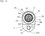
- FIG. 13 is a view similar to FIG. 4 , in which the check valve 1A according to the comparative example is viewed from the side.
- the check valve 1A according to the comparative embodiment differs from the present embodiment in that a snap ring 6A is used instead of a retaining ring, as illustrated in FIG. 12 .
- the snap ring 6A that is formed in a C shape from a plate material has end portions 65 and 66 projecting inward in the radial direction in a triangular shape in order to form holes 63 and 64 for inserting tools.
- the snap ring 6A When the snap ring 6A is mounted in the retaining ring attachment groove 243, it does not apply a pressing force (see FIG. 11 ) to both axial walls. Since the configuration other than the snap ring 6A is the same as the configuration of the present embodiment described above, the same reference numerals are given and a redundant description will be omitted.
- the triangular end portions 65 and 66 are in a state of greatly protruding into the flow path of the refrigerant, which hinders the flow of the refrigerant and can cause turbulence.
- a typical snap ring 6A since it is formed by processing a plate material by press molding or the like, the cost is relatively high.
- the corners are sharp edges, which further hinders the flow of the refrigerant passing through the inside of the snap ring 6A.
Landscapes
- Engineering & Computer Science (AREA)
- General Engineering & Computer Science (AREA)
- Mechanical Engineering (AREA)
- Check Valves (AREA)
- Valve Housings (AREA)
Abstract
Description
- The present invention relates to a flow path structure, a check valve comprising the same, and a manufacturing method of the check valve.
- Conventionally, in the refrigeration cycles used in air conditioning equipment such as car air conditioners, check valves are used to control the flow direction of the refrigerant (fluid).
-
Patent Document 1 discloses a three-way port check valve including a valve main body having a first inlet disposed on a common axis, a second inlet, a cylinder portion connecting them, and an outlet perpendicular to the cylinder portion. - In addition, the three-way port check valve of
Patent Document 1 includes a valve element slidable in the cylinder, and a stopper having an orifice provided in the vicinity of the second inlet. Accordingly, when the supply of the fluid from the second inlet side is interrupted and switched to the supply from the first inlet side, the valve element slides in the cylinder portion and hits the stopper due to the inflow pressure, and the tapered portion functions to seal the orifice. - On the other hand, in a state in which the valve element does not seal the orifice, the fluid flowing in from the second inlet passes through the flow path formed between the orifice, the cylinder, and the valve element, and flows to the outlet side.
- [Patent Document 1]
Japanese Unexamined Patent Application Publication No. H09-133235 A - Incidentally, the stopper of
Patent Document 1 is attached to the valve element by a snap ring fitted in a fitting groove formed in the vicinity of the second inlet. Typical snap rings are provided with holes at both end portions of a C-shaped plate material into which tools such as snap ring pliers can be inserted for ease of mounting. Accordingly, both end portions of the snap ring have a shape that protrudes toward the inner diameter side, but when the snap ring is attached to the fitting groove, both end portions often protrude into the flow path. - In the three-way port check valve of
Patent Document 1, since the orifice inner diameter of the stopper is smaller than the minimum diameter of the snap ring, there is little risk of suppressing the flow of the fluid flowing in from the second inlet even if a snap ring is used. In contrast to this, flow path structures in which snap rings are provided at positions that interfere with the fluid flowing through the flow path have also been developed. In the case of such a flow path structure, the part of the snap ring protruding into the flow path becomes a resistance to the flow, which may hinder the flow of the fluid or increase the pressure loss. In addition, since snap rings are relatively expensive, there is also a demand for further cost reduction. - The present invention has been made in view of the above problems, and has an object to provide a flow path structure, a check valve comprising the same, and a method for producing a check valve in which it is possible to ensure smooth flow of a fluid while reducing cost.
- The flow path structure according to the present invention comprises a hollow main body; and a retaining ring formed by processing a linear steel material into a C-shape, wherein: an annular fitting groove into which the retaining ring is fitted is provided inside of the main body, and a fluid flows inside the retaining ring fitted in the fitting groove.
- It should be noted that, since the flow path structure according to the present invention cannot be directly specified by its structure or characteristics, or it is substantially impractical to do so, a manufacturing method is described as part of the claims.
- According to the present invention, it is possible to provide a flow path structure, a check valve comprising the same, and a method for producing a check valve in which it is possible to ensure smooth flow of a fluid while reducing cost.
-
- [
Figure 1] FIG.1 is an axial cross-sectional view of the check valve according to the present embodiment. - [
Figure 2] FIG. 2 is an assembly perspective view of acheck valve 1 illustrated in a state in which the valve main body is split in half along the axis. - [
Figure 3] FIG. 3 is an exploded perspective view of acheck valve 1 illustrated in a state in which the valve main body is split in half along the axis. - [
Figure 4] FIG. 4 is a side view of the check valve from the direction of the arrow A inFIG 1 . - [
Figure 5] FIG. 5 is a diagram illustrating a state in which the retaining ring is placed on a flat surface. - [
Figure 6] FIG. 6 is a perspective view illustrating an example of a manufacturing device of a retaining ring. - [
Figure 7] FIG. 7 is a diagram illustrating an assembly process of the check valve. - [
Figure 8] FIG. 8 is a diagram illustrating an assembly process of the check valve. - [
Figure 9] FIG. 9 is a diagram illustrating an assembly process of the check valve. - [
Figure 10] FIG. 10 is a diagram illustrating an assembly process of the check valve. - [
Figure 11] FIG. 11 is a cross sectional view illustrating a cross section passing through the axis of the check valve, in which the retaining ring and the retaining ring attachment groove are cut. - [
Figure 12] FIG. 12 is an exploded view similar toFIG. 3 and illustrates a check valve according to a comparative example. - [
Figure 13] FIG. 13 is a view similar toFIG. 4 , in which the check valve according to the comparative example is viewed from the side. - Hereinafter, embodiments of the present invention will be described with reference to the drawings. It should be noted that, in the following, although an example will be described in which the flow path structure according to the present invention is primarily applied to a check valve for pressure adjustment used in the refrigeration cycle of a car air conditioner or the like, the flow path structure according to the present invention can be applied for various uses other than a check valve. Here, a "C-shape" refers to a shape in which the number of turns of a spiral shape is more than 0.5 and is less than 1, or a shape in which the angle formed by two straight lines connecting the center of the shape and both ends is more than 180 degrees and is less than 360 degrees. It should be noted that when the C-shaped member is placed on a flat surface, in the case that both ends are offset in the height direction, the C-shaped member is considered to be a part of a spiral shape. In addition, as the "linear steel member," for example, hard steel wire, piano wire, stainless steel wire, or the like may be used, but the present invention is not limited thereto.
-
FIG. 1 is an axial cross-sectional view of thecheck valve 1 according to the present embodiment.FIG. 2 is an assembly perspective view of thecheck valve 1 illustrated in a state in which the valvemain body 2 is split in half along the axis.FIG. 3 is an exploded perspective view of thecheck valve 1 illustrated in a state in which the valvemain body 2 is split in half along the axis.FIG. 4 is a side view of thecheck valve 1 from the direction of the arrow A inFIG. 1 . Here, L is set as the axis of the fluid passage of thecheck valve 1. - The
check valve 1 includes a hollow valve main body (also referred to as a main body) 2 having a refrigerant flow path (also referred to as a fluid passage) through which a refrigerant passes, avalve element 3 arranged in the fluid passage of the valvemain body 2, awasher 4 attached to the valvemain body 2, acoil spring 5 for biasing thevalve element 3 with respect to thewasher 4, and aretaining ring 6 for fixing thewasher 4 to the valvemain body 2. Thecheck valve 1 is connected to a joint to which, for example, a refrigerant pipe connected to an evaporator and a compressor (not illustrated in the figure) is connected, whereby a closed refrigeration cycle is formed. Here, as illustrated by the white arrow inFIG. 1 , the left side of thecheck valve 1 is considered to be the inlet side of the refrigerant, and the right side is considered to be the outlet side of the refrigerant. - The valve
main body 2 provided with the flow path structure has a substantially cylindrical first connectingportion 21, a firstintermediate passage 22, acentral passage 23, a substantially cylindrical secondintermediate passage 24, and a substantially cylindrical second connecting portion (a large-diameter cylindrical portion) 25 starting from the inlet side ofFIG. 1 along the axis L. Pipes (not illustrated in the figure) can be connected to the first connectingportion 21 and the second connectingportion 25, respectively. - The first
intermediate passage 22 connecting the first connectingportion 21 and thecentral passage 23 is formed by connecting a taperedtubular portion 221, a guidetubular portion 222 having a diameter smaller than that of the first connectingportion 21, and avalve seat 223 with a tapered diameter expanding toward thecentral passage 23 side. - On the other hand, the second
intermediate passage 24 connecting thecentral passage 23 and the second connectingportion 25 is formed by connecting a first linkingtubular portion 241, an annularwasher attachment portion 242, an annular retaining ring attachment groove (fitting groove) 243, and a second linkingtubular portion 244. The inner diameter of thewasher attachment portion 242 is larger than the inner diameter of the first linkingtubular portion 242, and the inner diameter of the retainingring attachment groove 243 is larger than the inner diameter of thewasher attachment portion 242. However, the inner diameter of the second linkingtubular portion 244 is smaller than the inner diameter of the retainingring attachment groove 243 and larger than the inner diameter of thewasher attachment portion 242. The inner diameter of the second connectingportion 25 is larger than the inner diameter of the retainingring attachment groove 243 and the inner diameter of the second linkingtubular portion 244. It should be noted that the size relationships of the inner diameters of each portion are not limited to the above-mentioned examples. For example, in the case that the inner diameter of thewasher attachment portion 242 is smaller than the inner diameter of the retainingring attachment groove 243, and the inner diameter of the retainingring attachment groove 243 is larger than the inner diameter of the second linkingtubular portion 244, the inner diameter of the second connectingportion 25 may be less than or equal to the inner diameter of the retainingring attachment groove 243, and the inner diameter of the second connectingportion 25 may be the same as the inner diameter of thewasher attachment portion 242. - Further, the valve
main body 2 has afirst arm portion 26 extending radially outward from the first connectingportion 21, and asecond arm portion 27 extending radially outward from the second connectingportion 25. Thefirst arm portion 26 is formed with ascrew hole 261 for screwing a bolt (not illustrated in the figure) for fixing a pipe connected to the first connectingportion 21, and thesecond arm portion 27 is formed with ascrew hole 271 for screwing a bolt (not illustrated in the figure) for fixing a pipe connected to the second connectingportion 25. - With reference to
FIG. 3 , thevalve element 3 is formed by connecting adisk portion 31, threeleg portions 32 extending from thedisk portion 31 along the axis L (FIG. 1 ) toward the first connectingportion 21 side, and threeleg portions 33 extending from thedisk portion 31 along the axis L toward the second connectingportion 25 side. The interval betweenadjacent leg portions 32 is wider than the interval between theadjacent leg portions 33, and the length of theleg portions 32 is shorter than the length of theleg portions 33. The space between theadjacent leg portions 32 becomes the flow path through which the refrigerant passes. - The outer circumferential surface of each
leg portion 32 is a part of the same cylindrical surface, and the outer diameter of this same cylindrical surface substantially coincides with the inner diameter of the guidetubular portion 222. Accordingly, when thevalve element 3 is installed on the valvemain body 2 as illustrated inFIG. 1 and FIG. 2 , thevalve element 3 is guided in the axis L direction by means of theleg portions 32 sliding in the guidetubular portion 222. - A
seal groove 311 is formed between thedisk portion 31 and theleg portions 32 as illustrated by the dotted line inFIG. 1 . An O-ring OR is arranged in theseal groove 311. - In
FIG. 3 , thewasher 4 has anannular portion 41 and a plurality (here, three)column portions 42 extending from theannular portion 41 toward the center of thewasher 4 at equal angles. The inner ends of thecolumn portions 42 are joined to each other. The outer diameter of thewasher 4 substantially matches the inner diameter of thewasher attachment portion 242. - At the time of assembly illustrated in
FIG. 1 and FIG. 2 , one end of thecoil spring 5 arranged around theleg portion 33 of thevalve element 3 comes into contact with the end surface of thedisk portion 31, and the other end of thecoil spring 5 is supported by thecolumn portion 42 of thewasher 4. Thecoil spring 5 biases thevalve element 3 toward the first connectingportion 21 side. - The
valve element 3 moves along the axis L in the valvemain body 2 in accordance with the refrigerant pressure, and has a function of allowing or blocking the passage of the refrigerant flowing in from the first connectingportion 21 side. -
FIG. 5 is a diagram illustrating a state in which theretaining ring 6 is placed on a flat surface PL. The retainingring 6 is a part of a linear steel material (or plate material) wound in a spiral shape, and has, for example, a uniform circular cross-sectional shape. Accordingly, as illustrated inFIG. 5 , when the retainingring 6 is placed on the flat surface PL, in a state in which oneend 61 is placed on the flat surface PL, theother end 62 is in a state suspended from the flat surface PL. Here, oneend 61 and theother end 62 are separated by a distance Δ along the height direction from the flat surface PL, and are also separated in the circumferential direction. -
FIG. 6 is a perspective view illustrating an example of a manufacturing device of the retainingring 6. In front of the metal linear steel material W fed through a feed roller (not illustrated in the figure), aguide 101, a bending die 102 for molding the linear steel material W into a coil shape having a predetermined curvature, acore metal 103 having a substantially semi-conical shape, and a pitch tool (not illustrated in the figure) that presses the linear steel material W that has been molded into a coil shape to form a predetermined pitch are installed so that they can move forward and backward with respect to the center of the coil. In addition, arotating shaft 104 provided with acutting blade 105 is rotatably arranged adjacent to thecore metal 103. - The linear steel material W fed by the feed roller is formed into a coil shape (a spiral shape) by passing through the
guide 101, thecore metal 103, the bending die 102 and the pitch tool. Before being completely molded into a coil shape, when molded a predetermined angle amount from the tip of the linear steel material W, by means of therotating shaft 104 rotating, thecutting blade 105 comes into contact with the linear steel material W from the outer diameter direction, and cuts the linear steel material W in cooperation with thecore metal 103. As a result, the retainingring 6 illustrated inFIG. 5 is formed. While continuously supplying the linear steel material W, each time thecutting blade 105 is intermittently rotationally moved, retainingrings 6 are continuously formed. - It should be noted that the method of manufacturing the
retaining ring 6 is not limited to the above-described embodiment. For example, using the manufacturing device ofFIG. 6 , a retainingring 6 can also be formed by forming a multi-wind coil with a spiral shape and then cutting the coil at predetermined angles. According to the molding method described above, the retainingring 6 can be manufactured at low cost. - Next, the operation of the
check valve 1 will be briefly described. InFIG. 1 and FIG. 2 , it is assumed that pipes are connected to the first connectingportion 21 and the second connectingportion 25, respectively. In the case that the refrigerant pressure of the first connectingportion 21 side is lower than the pressure obtained by applying a predetermined pressure (corresponding to the biasing force of the coil spring 5) to the refrigerant pressure of the second connectingportion 25 side, the O-ring OR of thevalve element 3 becomes seated on thevalve seat 223 of the valvemain body 2, which prevents the refrigerant from passing through thecheck valve 1, and the refrigerant does not flow out from the second connectingportion 25 side. - On the other hand, when the refrigerant pressure of the first connecting
portion 21 side becomes higher than the pressure obtained by applying a predetermined pressure to the refrigerant pressure of the second connectingportion 25 side, the valvemain body 3 moves in the valve opening direction (to the right inFIG. 1 ), the O-ring OR separates from thevalve seat 223, and the refrigerant is allowed to pass from the first connectingportion 21 side to the second connectingportion 25 side through the inside of the retainingring 6. - The assembly process of the
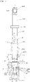
check valve 1 will be described with reference toFIG. 7 to FIG. 10 . As a preliminary step, as illustrated inFIG. 7 , a first assembly jig (a hollow cylindrical member) 110 and asecond assembly jig 120 are prepared. Thefirst assembly jig 110 has a substantially hollow cylindrical shape. More specifically, thefirst assembly jig 110 is formed by continuously connecting a thin-walledcylindrical portion 111 and a thick-walledcylindrical portion 112, and astep 113 is formed at the boundary of the cylindrical portion. The length of the thin-walledcylindrical portion 111 is B, the inner diameter thereof is C, and the outer diameter thereof is D. On the other hand, the inner circumference of the thick-walledcylindrical portion 112 has a tapered cylindrical shape in which the diameter gradually increases as the distance from the thin-walledcylindrical portion 111 increases, where the minimum inner diameter thereof is C, and the maximum inner diameter thereof is E. - The second
cylindrical assembly jig 120 includes aflange portion 121, a large cylindrical portion (an assembly jig) 122 protruding from one surface of theflange portion 121, and a small cylindrical portion (a small diameter assembly jig) 123 protruding from another surface of theflange portion 121. The outer diameter F of the largecylindrical portion 122 is larger than the outer diameter G of the smallcylindrical portion 123. In addition, the length of the largecylindrical portion 122 is shorter than the length of the smallcylindrical portion 123. A recessedportion 124 is formed in the center of the end surface of the smallcylindrical portion 123. - In addition, the distance from the
end surface 251 of the second connectingportion 25 side of the valvemain body 2 to the boundary between the secondlinking tubular portion 244 and the retainingring attachment groove 243 is H, the inner diameter of the secondlinking tubular portion 244 is I, and the outer diameter of thewasher 4 is J. - Further, the inner diameter of the retaining
ring 6 in a free state (a state in which no external force is applied) is K, and the outer diameter thereof is M. - Hereinafter, the assembly process of the
check valve 1 will be sequentially described. Here, by arranging the valvemain body 2 such that the axis L faces the vertical direction and the second connectingportion 25 is positioned upward in the gravity direction, each part can be assembled using gravity. - As illustrated in
FIG. 7 , thevalve element 3 equipped with the O-ring OR, and thecoil spring 5 are inserted into the valvemain body 2. Subsequently, thecolumn portions 42 of thewasher 4 are inserted between each of theleg portions 33 of thevalve element 3, and thewasher 4 is arranged at the upper end of thecoil spring 5. In this state, thewasher 4 is biased upward by thecoil spring 5 and does not reach thewasher attachment portion 242. - It should be noted that, since the inner diameter I of the second
linking tubular portion 244 is larger than the outer diameter J of thewasher 4, thewasher 4 can pass through the secondlinking tubular portion 244. - Further, the thin-walled
cylindrical portion 111 of thefirst assembly jig 110 is inserted into the secondlinking tubular portion 244 through the second connectingportion 25. Since the inner diameter I of the secondlinking tubular portion 244 is larger than the outer diameter D of the thin-walledcylindrical portion 111 of thefirst assembly jig 110, the thin-walledcylindrical portion 111 is allowed to be inserted. - The
first assembly jig 110 is inserted into the valvemain body 2 until thestep 113 of thefirst assembly jig 110 comes into contact with theend surface 251 of the valvemain body 2. Here, since the distance H from theend surface 251 of thesecond connection portion 25 side to the boundary between the secondlinking tubular portion 244 and the retainingring attachment groove 243 and the length B of the thin-walledcylindrical portion 111 are substantially equal to each other, when thestep 113 comes into contact with theend surface 251, the tip of the thin-walledcylindrical portion 111 is located at the boundary between the secondlinking tubular portion 244 and the retaining ring attachment groove 243 (seeFIG. 8 ). - Next, as illustrated in
FIG. 8 , the retainingring 6 is inserted from the inner circumferential large-diameter end side of the thick-walledcylindrical portion 112 of thefirst assembly jig 110, and further, the retainingring 6 is driven further by using the largecylindrical portion 122 of thesecond assembly jig 120. - Here, since the maximum inner diameter E of the thick-walled
cylindrical portion 112 is larger than the outer diameter M of the retainingring 6 in a free state, the retainingring 6 can be inserted into the thick-walledcylindrical portion 112 without applying any external force to the retainingring 6. In addition, since the outer diameter F of the largecylindrical portion 122 of thesecond assembly jig 120 is smaller than the maximum inner diameter E of the thick-walledcylindrical portion 112, the largecylindrical portion 122 can be smoothly inserted into the thick-walledcylindrical portion 112. - Further, since the inner diameter K of the retaining
ring 6 in a free state is smaller than the outer diameter F of the largecylindrical portion 122, the retainingring 6 can be pushed in without the largecylindrical portion 122 passing through the retainingring 6. The diameter of the retainingring 6 gradually decreases as it is pushed along the tapered inner circumferential surface of the thick-walledcylindrical portion 112. - When the
flange portion 121 of thesecond assembly jig 120 comes into contact with theend surface 114 of the thick-walledcylindrical portion 112, the retainingring 6 enters to about 1/3 of the length of the thick-walledcylindrical portion 112. At this time, the inner diameter of the retainingring 6 is reduced while being elastically deformed by being pressed from the tapered inner circumferential surface of the thick-walledcylindrical portion 112, such that it becomes smaller than the outer diameter G of the smallcylindrical portion 123 of thesecond assembly jig 120. - Accordingly, the
second assembly jig 120 is pulled out once and inverted, and then, as illustrated inFIG. 9 , the smallcylindrical portion 123 is inserted into the tapered inner circumferential surface of the thick-walledcylindrical portion 112, pressed against the retainingring 6, and further driven to pass through the inner circumferential surface of the thin-walledcylindrical portion 111. At this time, theleg portions 33 of thevalve element 3 protrude into the second connectingportion 25, but since the recessedportion 124 is formed at the tip of the smallcylindrical portions 123, interference between the smallcylindrical portion 123 and theleg portions 33 can be avoided. - The reason why the
second assembly jig 120 is inverted and the retainingring 6 is pressed in two steps is because the amount of diameter reduction of the retainingring 6 when the retainingring 6 is displaced along the tapered inner circumferential surface is relatively large. That is, the smallcylindrical portion 123 cannot be pressed because it slips through the inside of the retainingring 6 prior to the diameter reduction on the inner circumferential large diameter end side, and the largecylindrical portion 122 comes into contact with the inner circumference of thefirst assembly jig 110 on the small diameter end side such that the retainingring 6 cannot be pressed. It should be noted that after pulling out thesecond assembly jig 120, the retainingring 6 may be pressed by using another jig without inverting it. - As described above, since the retaining
ring 6 is manufactured by a simple process of cutting a linear steel material (or plate material), the cut surfaces of oneend 61 and theother end 62 are rough, and there is a high likelihood that burrs and the like may remain. Accordingly, if the retainingring 6 were assembled to the valvemain body 2 as it is, the inner circumferential surface of the valvemain body 2 may be damaged by the cut end of the retainingring 6. - In contrast, according to the present embodiment, by inserting the thin-walled
cylindrical portion 111 of thefirst assembly jig 110 into the valvemain body 2, the thin-walledcylindrical portion 111 protects the second connectingportion 25 or the like, and it is possible to prevent the inner circumferential surface of the valvemain body 2 from being damaged by the cut end of the retainingring 6. - As illustrated in
FIG. 10 , the retainingring 6 that has passed through the thin-walledcylindrical portion 111 by means of the smallcylindrical portion 123 of thesecond assembly jig 120 is pushed out from the end portion thereof (the inner circumferential small diameter end) to the outside of thefirst assembly jig 110. At this time, the retainingring 6 is released from its compressed state, recovers from the elastic deformation, expands in diameter, and fits into the retainingring attachment groove 243 adjacent to the thin-walledcylindrical portion 111. - At this time, since the retaining
ring 6 is part of the spiral shape, as illustrated inFIG. 11 , when fitted in the retainingring attachment groove 243, both ends 61 and 62, which are separated by a distance Δ (FIG. 6 ) in a free state, press the walls on both sides of the retainingring attachment groove 243 in the axial direction by elastic deformation, thereby exerting a retaining effect. - Further, the retaining
ring 6 pushed out by thesecond assembly jig 120 comes into contact with thewasher 4 located below and pushes thewasher 4 to thewasher attachment portion 242. Since thewasher 4 is biased toward the retainingring 6 by the biasing force of thecoil spring 5, thewasher 4 is maintained in a state of being fixed to the valvemain body 2. Subsequently, by pulling out thesecond assembly jig 120 and thefirst assembly jig 110 from the valvemain body 2, the assembly of thecheck valve 1 is completed. -
FIG. 12 is an exploded view similar toFIG. 3 and illustrates acheck valve 1A according to a comparative example.FIG. 13 is a view similar toFIG. 4 , in which thecheck valve 1A according to the comparative example is viewed from the side. Thecheck valve 1A according to the comparative embodiment differs from the present embodiment in that asnap ring 6A is used instead of a retaining ring, as illustrated inFIG. 12 . - The
snap ring 6A that is formed in a C shape from a plate material hasend portions holes snap ring 6A is mounted in the retainingring attachment groove 243, it does not apply a pressing force (seeFIG. 11 ) to both axial walls. Since the configuration other than thesnap ring 6A is the same as the configuration of the present embodiment described above, the same reference numerals are given and a redundant description will be omitted. - As is clear from the direction illustrated in
FIG. 13 , in the state where thecheck valve 1A of the comparative example is assembled, thetriangular end portions - Further, in a
typical snap ring 6A, since it is formed by processing a plate material by press molding or the like, the cost is relatively high. In addition, in the cross section of thesnap ring 6A, the corners are sharp edges, which further hinders the flow of the refrigerant passing through the inside of thesnap ring 6A. - In contrast to this, according to the present embodiment, as illustrated in
FIG. 4 , since bothend portions ring 6 are separated in the circumferential direction in a cut state, a large flow path cross-sectional area can be secured as compared with the comparative example. Further, as illustrated inFIG. 11 , even in a state where a part of the retainingring 6 protrudes radially inward from the retainingring attachment groove 243, the cross section of the retainingring 6 is circular, such that the flow of the refrigerant passing through the inside of the retainingring 6 is not easily obstructed. - It should be noted that the present invention is not limited to the above-described embodiments. Within the scope of the present invention, any component of the above-described embodiments can be modified. In addition, any component can be added or omitted in the above-described embodiments.
-
- 1 Check valve
- 2 Valve main body
- 3 Valve element
- 4 Washer
- 5 Coil spring
- 6 Retaining ring
- OR O-ring
- L Axis
Claims (12)
- A flow path structure comprising:a hollow main body; anda retaining ring formed by processing a linear steel material into a C-shape,wherein:an annular fitting groove into which the retaining ring is fitted is provided inside of the main body, anda fluid flows inside the retaining ring fitted in the fitting groove.
- The flow path structure according to claim 1, wherein the retaining ring forms part of a spiral shape.
- The flow path structure according to claim 1, wherein the retaining ring is formed of a linear steel material having a circular cross section bent into a C-shape.
- The flow path structure according to any one of claims 1 to 3, wherein the retaining ring is formed by cutting a linear steel material that has been wound in a spiral shape.
- The flow path structure according to any one of claims 1 to 3, wherein the retaining ring is formed by cutting a linear steel material while winding it into a spiral shape.
- A check valve comprising:a flow path structure according to any one of claims 1 to 5;a valve element arranged in the main body; anda coil spring that biases the valve element toward a valve seat,wherein:
the coil spring is fixed to the main body via the retaining ring. - The check valve according to claim 6, wherein the main body is provided with a large-diameter cylindrical portion that is adjacent to the fitting groove and has an inner diameter larger than that of the fitting groove.
- A manufacturing method of the check valve according to claim 7, the manufacturing method comprising:a step of arranging a hollow cylindrical member having a tapered inner circumferential surface inside the large-diameter cylindrical portion;a step of inserting the retaining ring from an inner circumferential large-diameter end side of the hollow cylindrical member and reducing the diameter of the retaining ring while elastically deforming it by displacing it along the tapered inner circumferential surface; anda step of pushing out the retaining ring from an inner circumferential small diameter end side of the hollow cylindrical member and fitting it into the fitting groove.
- The manufacturing method of the check valve according to claim 8, wherein the step of reducing the diameter includes inserting the retaining ring from the inner circumferential large-diameter end side of the hollow cylindrical member with an assembly jig having an outer diameter that is smaller than a maximum inner diameter of the tapered inner circumferential surface of the hollow cylindrical member and larger than a minimum inner diameter thereof.
- The manufacturing method of the check valve according to claim 9, wherein the step of reducing the diameter includes driving, after inserting the retaining ring with the assembly jig, the retaining ring further toward the inner circumferential small diameter end side with a small diameter assembly jig having an outer diameter smaller than that of the assembly jig.
- The manufacturing method of the check valve according to claim 10, wherein the assembly jig and the small diameter assembly jig are integrally configured.
- The manufacturing method of the check valve according to any one of claims 8 to 11, wherein an outer diameter of the retaining ring in a free state is smaller than the maximum inner diameter of the hollow cylindrical member.
Applications Claiming Priority (3)
| Application Number | Priority Date | Filing Date | Title |
|---|---|---|---|
| JP2019122055 | 2019-06-28 | ||
| JP2019122046 | 2019-06-28 | ||
| PCT/JP2020/024428 WO2020262308A1 (en) | 2019-06-28 | 2020-06-22 | Flow path structure, check valve comprising same, and method for producing check valve |
Publications (2)
| Publication Number | Publication Date |
|---|---|
| EP3991873A1 true EP3991873A1 (en) | 2022-05-04 |
| EP3991873A4 EP3991873A4 (en) | 2023-07-26 |
Family
ID=74059976
Family Applications (1)
| Application Number | Title | Priority Date | Filing Date |
|---|---|---|---|
| EP20831089.6A Withdrawn EP3991873A4 (en) | 2019-06-28 | 2020-06-22 | Flow path structure, check valve comprising same, and method for producing check valve |
Country Status (4)
| Country | Link |
|---|---|
| EP (1) | EP3991873A4 (en) |
| JP (1) | JP7158785B2 (en) |
| CN (1) | CN114051570A (en) |
| WO (1) | WO2020262308A1 (en) |
Cited By (2)
| Publication number | Priority date | Publication date | Assignee | Title |
|---|---|---|---|---|
| EP4368310A1 (en) * | 2022-11-08 | 2024-05-15 | BeijingWest Industries Co. Ltd. | Method and system for on-demand retaining ring forming and installation |
| US12059721B2 (en) | 2022-11-08 | 2024-08-13 | Beijingwest Industries Co., Ltd. | Method and system for on-demand retaining ring forming and installation |
Families Citing this family (2)
| Publication number | Priority date | Publication date | Assignee | Title |
|---|---|---|---|---|
| CN115875487A (en) * | 2022-12-23 | 2023-03-31 | 浙江银轮新能源热管理系统有限公司 | One-way valve |
| CN117245335B (en) * | 2023-07-28 | 2025-11-04 | 江西昌河航空工业有限公司 | Processing method for high-temperature gas-tight one-way valve |
Family Cites Families (8)
| Publication number | Priority date | Publication date | Assignee | Title |
|---|---|---|---|---|
| JPS5697617A (en) * | 1980-01-07 | 1981-08-06 | Mitsubishi Motors Corp | Ccshaped coaxial stop ring and its manufacture |
| JPS59181377U (en) * | 1983-05-20 | 1984-12-04 | 株式会社 田「淵」製作所 | check valve valve body |
| JPH09133235A (en) | 1995-11-06 | 1997-05-20 | Fuji Koki:Kk | Three-way check valve |
| US6206032B1 (en) * | 2000-07-11 | 2001-03-27 | James H. Hill | High pressure check valve fittings |
| US20110036423A1 (en) * | 2009-08-12 | 2011-02-17 | Chen-Hsing Yi | Relief Valve Device |
| JP5914031B2 (en) * | 2012-02-17 | 2016-05-11 | Ntn株式会社 | Electric linear actuator |
| JP6113688B2 (en) * | 2014-07-11 | 2017-04-12 | 日東工器株式会社 | Valve device and pipe joint provided with valve device |
| EP3260712B1 (en) * | 2016-06-24 | 2021-04-07 | Kubota Corporation | Device with adjustment bolt |
-
2020
- 2020-06-22 EP EP20831089.6A patent/EP3991873A4/en not_active Withdrawn
- 2020-06-22 JP JP2021526975A patent/JP7158785B2/en active Active
- 2020-06-22 CN CN202080047194.4A patent/CN114051570A/en not_active Withdrawn
- 2020-06-22 WO PCT/JP2020/024428 patent/WO2020262308A1/en not_active Ceased
Cited By (2)
| Publication number | Priority date | Publication date | Assignee | Title |
|---|---|---|---|---|
| EP4368310A1 (en) * | 2022-11-08 | 2024-05-15 | BeijingWest Industries Co. Ltd. | Method and system for on-demand retaining ring forming and installation |
| US12059721B2 (en) | 2022-11-08 | 2024-08-13 | Beijingwest Industries Co., Ltd. | Method and system for on-demand retaining ring forming and installation |
Also Published As
| Publication number | Publication date |
|---|---|
| CN114051570A (en) | 2022-02-15 |
| WO2020262308A1 (en) | 2020-12-30 |
| JPWO2020262308A1 (en) | 2020-12-30 |
| EP3991873A4 (en) | 2023-07-26 |
| JP7158785B2 (en) | 2022-10-24 |
Similar Documents
| Publication | Publication Date | Title |
|---|---|---|
| JP7158785B2 (en) | Flow path structure, check valve having the same, and method for manufacturing check valve | |
| EP3828450B1 (en) | Electric valve | |
| CN105074309A (en) | Insert connecting piece for connecting pipes, and tool for an insert connecting piece | |
| JP7471489B2 (en) | Manufacturing method of check valve unit | |
| US5096234A (en) | Method of fastening hose to nipple and hose connection obtained by such method | |
| US9964241B2 (en) | Connection assembly | |
| JP7628605B2 (en) | Fluid Connection Assembly | |
| EP3951223B1 (en) | Check valve manufacturing method | |
| US9920843B2 (en) | Spring gasket for a valve housing | |
| JP5039694B2 (en) | Improved swage tool | |
| EP2882986A1 (en) | Valve housing with collared spindle guide | |
| CN218582348U (en) | Insert check valve for fluid circuit, pipe part and vehicle | |
| US7533689B2 (en) | Excess flow control valve | |
| CN110735941B (en) | Control valve and manufacturing method thereof | |
| CN212273124U (en) | Flow regulating pipe and pipeline system | |
| CN111140687A (en) | Electronic expansion valve | |
| US20050039798A1 (en) | Tubular flow conduit with in-line integrated check valve and method of making same | |
| CN116928405A (en) | Method for manufacturing one-way valve and one-way valve | |
| CN204226783U (en) | Heating power expansion valve | |
| CN221278543U (en) | Float-type one-way valve and air conditioning system | |
| US6751996B2 (en) | Dynamic punch | |
| CN105626922A (en) | TXV (thermostatic expansion valve) | |
| KR20030050328A (en) | Check valve | |
| EP4547987A1 (en) | Non-return valve, in particular for a refrigeration or heat circuit | |
| JPH11262949A (en) | Connection end expansion jig for synthetic resin fluid pipe |
Legal Events
| Date | Code | Title | Description |
|---|---|---|---|
| STAA | Information on the status of an ep patent application or granted ep patent |
Free format text: STATUS: THE INTERNATIONAL PUBLICATION HAS BEEN MADE |
|
| PUAI | Public reference made under article 153(3) epc to a published international application that has entered the european phase |
Free format text: ORIGINAL CODE: 0009012 |
|
| STAA | Information on the status of an ep patent application or granted ep patent |
Free format text: STATUS: REQUEST FOR EXAMINATION WAS MADE |
|
| 17P | Request for examination filed |
Effective date: 20211221 |
|
| AK | Designated contracting states |
Kind code of ref document: A1 Designated state(s): AL AT BE BG CH CY CZ DE DK EE ES FI FR GB GR HR HU IE IS IT LI LT LU LV MC MK MT NL NO PL PT RO RS SE SI SK SM TR |
|
| DAV | Request for validation of the european patent (deleted) | ||
| DAX | Request for extension of the european patent (deleted) | ||
| RIN1 | Information on inventor provided before grant (corrected) |
Inventor name: FUKUYAMA, KOHEI Inventor name: MOCHIZUKI, ATSUSHI Inventor name: YAMABE, SHIMPEI |
|
| A4 | Supplementary search report drawn up and despatched |
Effective date: 20230622 |
|
| RIC1 | Information provided on ipc code assigned before grant |
Ipc: B23P 15/00 20060101ALI20230616BHEP Ipc: F16K 15/06 20060101ALI20230616BHEP Ipc: F16K 27/02 20060101ALI20230616BHEP Ipc: B21F 3/06 20060101ALI20230616BHEP Ipc: F16B 21/18 20060101ALI20230616BHEP Ipc: B23P 19/02 20060101ALI20230616BHEP Ipc: F16K 15/02 20060101ALI20230616BHEP Ipc: B21F 37/02 20060101ALI20230616BHEP Ipc: B21F 11/00 20060101AFI20230616BHEP |
|
| STAA | Information on the status of an ep patent application or granted ep patent |
Free format text: STATUS: THE APPLICATION IS DEEMED TO BE WITHDRAWN |
|
| 18D | Application deemed to be withdrawn |
Effective date: 20240123 |