EP3991710B1 - Adjustable back plate for mechanical compression device - Google Patents
Adjustable back plate for mechanical compression device Download PDFInfo
- Publication number
- EP3991710B1 EP3991710B1 EP21205640.2A EP21205640A EP3991710B1 EP 3991710 B1 EP3991710 B1 EP 3991710B1 EP 21205640 A EP21205640 A EP 21205640A EP 3991710 B1 EP3991710 B1 EP 3991710B1
- Authority
- EP
- European Patent Office
- Prior art keywords
- backboard
- compression device
- chest compression
- orientation
- patient
- Prior art date
- Legal status (The legal status is an assumption and is not a legal conclusion. Google has not performed a legal analysis and makes no representation as to the accuracy of the status listed.)
- Active
Links
Images












Classifications
-
- A—HUMAN NECESSITIES
- A61—MEDICAL OR VETERINARY SCIENCE; HYGIENE
- A61H—PHYSICAL THERAPY APPARATUS, e.g. DEVICES FOR LOCATING OR STIMULATING REFLEX POINTS IN THE BODY; ARTIFICIAL RESPIRATION; MASSAGE; BATHING DEVICES FOR SPECIAL THERAPEUTIC OR HYGIENIC PURPOSES OR SPECIFIC PARTS OF THE BODY
- A61H31/00—Artificial respiration by a force applied to the chest; Heart stimulation, e.g. heart massage
- A61H31/004—Heart stimulation
-
- A—HUMAN NECESSITIES
- A61—MEDICAL OR VETERINARY SCIENCE; HYGIENE
- A61H—PHYSICAL THERAPY APPARATUS, e.g. DEVICES FOR LOCATING OR STIMULATING REFLEX POINTS IN THE BODY; ARTIFICIAL RESPIRATION; MASSAGE; BATHING DEVICES FOR SPECIAL THERAPEUTIC OR HYGIENIC PURPOSES OR SPECIFIC PARTS OF THE BODY
- A61H31/00—Artificial respiration by a force applied to the chest; Heart stimulation, e.g. heart massage
- A61H31/008—Supine patient supports or bases, e.g. improving air-way access to the lungs
-
- A—HUMAN NECESSITIES
- A61—MEDICAL OR VETERINARY SCIENCE; HYGIENE
- A61H—PHYSICAL THERAPY APPARATUS, e.g. DEVICES FOR LOCATING OR STIMULATING REFLEX POINTS IN THE BODY; ARTIFICIAL RESPIRATION; MASSAGE; BATHING DEVICES FOR SPECIAL THERAPEUTIC OR HYGIENIC PURPOSES OR SPECIFIC PARTS OF THE BODY
- A61H2201/00—Characteristics of apparatus not provided for in the preceding codes
- A61H2201/01—Constructive details
- A61H2201/0107—Constructive details modular
-
- A—HUMAN NECESSITIES
- A61—MEDICAL OR VETERINARY SCIENCE; HYGIENE
- A61H—PHYSICAL THERAPY APPARATUS, e.g. DEVICES FOR LOCATING OR STIMULATING REFLEX POINTS IN THE BODY; ARTIFICIAL RESPIRATION; MASSAGE; BATHING DEVICES FOR SPECIAL THERAPEUTIC OR HYGIENIC PURPOSES OR SPECIFIC PARTS OF THE BODY
- A61H2201/00—Characteristics of apparatus not provided for in the preceding codes
- A61H2201/01—Constructive details
- A61H2201/0157—Constructive details portable
-
- A—HUMAN NECESSITIES
- A61—MEDICAL OR VETERINARY SCIENCE; HYGIENE
- A61H—PHYSICAL THERAPY APPARATUS, e.g. DEVICES FOR LOCATING OR STIMULATING REFLEX POINTS IN THE BODY; ARTIFICIAL RESPIRATION; MASSAGE; BATHING DEVICES FOR SPECIAL THERAPEUTIC OR HYGIENIC PURPOSES OR SPECIFIC PARTS OF THE BODY
- A61H2201/00—Characteristics of apparatus not provided for in the preceding codes
- A61H2201/01—Constructive details
- A61H2201/0161—Size reducing arrangements when not in use, for stowing or transport
-
- A—HUMAN NECESSITIES
- A61—MEDICAL OR VETERINARY SCIENCE; HYGIENE
- A61H—PHYSICAL THERAPY APPARATUS, e.g. DEVICES FOR LOCATING OR STIMULATING REFLEX POINTS IN THE BODY; ARTIFICIAL RESPIRATION; MASSAGE; BATHING DEVICES FOR SPECIAL THERAPEUTIC OR HYGIENIC PURPOSES OR SPECIFIC PARTS OF THE BODY
- A61H2201/00—Characteristics of apparatus not provided for in the preceding codes
- A61H2201/01—Constructive details
- A61H2201/0192—Specific means for adjusting dimensions
-
- A—HUMAN NECESSITIES
- A61—MEDICAL OR VETERINARY SCIENCE; HYGIENE
- A61H—PHYSICAL THERAPY APPARATUS, e.g. DEVICES FOR LOCATING OR STIMULATING REFLEX POINTS IN THE BODY; ARTIFICIAL RESPIRATION; MASSAGE; BATHING DEVICES FOR SPECIAL THERAPEUTIC OR HYGIENIC PURPOSES OR SPECIFIC PARTS OF THE BODY
- A61H2201/00—Characteristics of apparatus not provided for in the preceding codes
- A61H2201/01—Constructive details
- A61H2201/0192—Specific means for adjusting dimensions
- A61H2201/0196—Specific means for adjusting dimensions automatically adjusted according to anthropometric data of the user
-
- A—HUMAN NECESSITIES
- A61—MEDICAL OR VETERINARY SCIENCE; HYGIENE
- A61H—PHYSICAL THERAPY APPARATUS, e.g. DEVICES FOR LOCATING OR STIMULATING REFLEX POINTS IN THE BODY; ARTIFICIAL RESPIRATION; MASSAGE; BATHING DEVICES FOR SPECIAL THERAPEUTIC OR HYGIENIC PURPOSES OR SPECIFIC PARTS OF THE BODY
- A61H2201/00—Characteristics of apparatus not provided for in the preceding codes
- A61H2201/16—Physical interface with patient
- A61H2201/1602—Physical interface with patient kind of interface, e.g. head rest, knee support or lumbar support
- A61H2201/1604—Head
- A61H2201/1607—Holding means therefor
-
- A—HUMAN NECESSITIES
- A61—MEDICAL OR VETERINARY SCIENCE; HYGIENE
- A61H—PHYSICAL THERAPY APPARATUS, e.g. DEVICES FOR LOCATING OR STIMULATING REFLEX POINTS IN THE BODY; ARTIFICIAL RESPIRATION; MASSAGE; BATHING DEVICES FOR SPECIAL THERAPEUTIC OR HYGIENIC PURPOSES OR SPECIFIC PARTS OF THE BODY
- A61H2201/00—Characteristics of apparatus not provided for in the preceding codes
- A61H2201/16—Physical interface with patient
- A61H2201/1602—Physical interface with patient kind of interface, e.g. head rest, knee support or lumbar support
- A61H2201/1623—Back
- A61H2201/1626—Holding means therefor
-
- A—HUMAN NECESSITIES
- A61—MEDICAL OR VETERINARY SCIENCE; HYGIENE
- A61H—PHYSICAL THERAPY APPARATUS, e.g. DEVICES FOR LOCATING OR STIMULATING REFLEX POINTS IN THE BODY; ARTIFICIAL RESPIRATION; MASSAGE; BATHING DEVICES FOR SPECIAL THERAPEUTIC OR HYGIENIC PURPOSES OR SPECIFIC PARTS OF THE BODY
- A61H2201/00—Characteristics of apparatus not provided for in the preceding codes
- A61H2201/50—Control means thereof
- A61H2201/5007—Control means thereof computer controlled
-
- A—HUMAN NECESSITIES
- A61—MEDICAL OR VETERINARY SCIENCE; HYGIENE
- A61H—PHYSICAL THERAPY APPARATUS, e.g. DEVICES FOR LOCATING OR STIMULATING REFLEX POINTS IN THE BODY; ARTIFICIAL RESPIRATION; MASSAGE; BATHING DEVICES FOR SPECIAL THERAPEUTIC OR HYGIENIC PURPOSES OR SPECIFIC PARTS OF THE BODY
- A61H2201/00—Characteristics of apparatus not provided for in the preceding codes
- A61H2201/50—Control means thereof
- A61H2201/5097—Control means thereof wireless
-
- A—HUMAN NECESSITIES
- A61—MEDICAL OR VETERINARY SCIENCE; HYGIENE
- A61H—PHYSICAL THERAPY APPARATUS, e.g. DEVICES FOR LOCATING OR STIMULATING REFLEX POINTS IN THE BODY; ARTIFICIAL RESPIRATION; MASSAGE; BATHING DEVICES FOR SPECIAL THERAPEUTIC OR HYGIENIC PURPOSES OR SPECIFIC PARTS OF THE BODY
- A61H31/00—Artificial respiration by a force applied to the chest; Heart stimulation, e.g. heart massage
- A61H31/004—Heart stimulation
- A61H31/006—Power driven
Definitions
- This disclosure is directed to systems and methods related to mechanical cardiopulmonary resuscitation (CPR) devices, and in particular, to adjustable back plates or backboards that support a patient and accommodate a variety of patient sizes.
- CPR cardiopulmonary resuscitation
- Mechanical compression devices for CPR are being increasingly adopted by emergency medical services around the world. Patients, however, come in a wide variety of sizes and many mechanical compression devices are designed to only accommodate patients of a certain size. However, some patients have a body habitus that falls outside the acceptable range for the device's specifications and therefore can be excluded from receiving the benefits of mechanical CPR. For example, patients that are smaller or pediatric, as well as larger patients, may not fit within the acceptable range for the device's specifications.
- Some clinicians have developed ad-hoc solutions, especially for pediatric patients. For example, sometimes clinicians will place a towel underneath a pediatric patient and/or configure the piston of the CPR device to start compression one to two centimeters above the sternum of the patient. Such ad-hoc approaches can lead to significant injury to the patient if not performed correctly. For example, if a compression depth is not controlled correctly, it can lead to rupture of the heart or other organs.
- Document US 2019/0008720 discloses an automated chest compression (CC) system that includes a chest compressor configured to administer chest compressions to a patient and discloses a patient tilt support which may couple to the platform at a pivot point and allows to adjust a tilt angle and a distance of the patient support from the support surface.
- CC automated chest compression
- Document US 2017/0348190 discloses a back plate for use with a CPR compression device which comprises first and second static attachment elements configured on first and second sides, respectively, to releasably connect to first and second legs, respectively.
- Document CN 103040602A discloses an electric control pneumatic cardio-pulmonary resuscitation machine and belongs to the field of medical machinery.
- Example 1 includes a backboard for a chest compression device, comprising: a first side structured to accommodate an adult-sized patient at a first distance from a surface when attached to the chest compression device in a first orientation; and a second side structured to accommodate a pediatric-sized patient at a second distance from the surface, the second distance being greater than the first distance, when attached to the chest compression device in a second orientation.
- Example 2 includes the backboard of Example 1, wherein the first side includes two attachment points, each attachment point structured to attach a respective leg of the chest compression device to the backboard when in the first orientation, and wherein the second first side includes two attachment points, each attachment point structured to attach a respective leg of the chest compression device to the backboard when in the second orientation.
- Example 3 includes the backboard of any of Examples 1-2, wherein the first side has a first curvature and the second side has a second curvature different from the first curvature.
- Example 15 includes the backboard of Example 12, wherein the backboard is wedge-shaped.
- Example 4 includes the backboard of any of Examples 1-3, further comprising a retractable headrest.
- Example 11 includes the chest compression device of Example 10, wherein the characteristic includes at least one of an angle of a leg of the chest compression device connected to a respective connector of the backboard or a size of an anchoring point of the respective connector.
Landscapes
- Health & Medical Sciences (AREA)
- Heart & Thoracic Surgery (AREA)
- Cardiology (AREA)
- Pain & Pain Management (AREA)
- Pulmonology (AREA)
- Epidemiology (AREA)
- Emergency Medicine (AREA)
- Physical Education & Sports Medicine (AREA)
- Rehabilitation Therapy (AREA)
- Life Sciences & Earth Sciences (AREA)
- Animal Behavior & Ethology (AREA)
- General Health & Medical Sciences (AREA)
- Public Health (AREA)
- Veterinary Medicine (AREA)
- Percussion Or Vibration Massage (AREA)
Description
- This patent application claims the benefit of
U.S. provisional application no. 63/158,800 filed March 9, 2021 U.S. provisional application no. 63/107,184 filed October 29, 2020 - This disclosure is directed to systems and methods related to mechanical cardiopulmonary resuscitation (CPR) devices, and in particular, to adjustable back plates or backboards that support a patient and accommodate a variety of patient sizes.
- Mechanical compression devices for CPR are being increasingly adopted by emergency medical services around the world. Patients, however, come in a wide variety of sizes and many mechanical compression devices are designed to only accommodate patients of a certain size. However, some patients have a body habitus that falls outside the acceptable range for the device's specifications and therefore can be excluded from receiving the benefits of mechanical CPR. For example, patients that are smaller or pediatric, as well as larger patients, may not fit within the acceptable range for the device's specifications.
- Some clinicians have developed ad-hoc solutions, especially for pediatric patients. For example, sometimes clinicians will place a towel underneath a pediatric patient and/or configure the piston of the CPR device to start compression one to two centimeters above the sternum of the patient. Such ad-hoc approaches can lead to significant injury to the patient if not performed correctly. For example, if a compression depth is not controlled correctly, it can lead to rupture of the heart or other organs.
- Given the growing evidence of benefits of using mechanical compressions, especially in longer duration resuscitations, and the risk of either not being able to perform the compressions or doing so using ad-hoc approaches, a solution is needed for delivering precise, consistent, predictable, and safe mechanical compression for smaller patients and larger patients that do not fit within the acceptable body size for current mechanical devices.
- Configurations of the disclosed technology address shortcomings in the prior art.
- Document
US 2019/0008720 discloses an automated chest compression (CC) system that includes a chest compressor configured to administer chest compressions to a patient and discloses a patient tilt support which may couple to the platform at a pivot point and allows to adjust a tilt angle and a distance of the patient support from the support surface. - Document
US 3,985,126 discloses support and retention including an upper back supporting portion spaced in part at least from the base providing a clearance opening for insertion of a mechanical compressor platform without requiring movement of the patient. - Document
US 2017/0348190 discloses a back plate for use with a CPR compression device which comprises first and second static attachment elements configured on first and second sides, respectively, to releasably connect to first and second legs, respectively. - Document
CN 103040602A discloses an electric control pneumatic cardio-pulmonary resuscitation machine and belongs to the field of medical machinery. - The invention is set out in the appended claims.
- The description and drawings related to
Figures 2-14 ,21-33 , and38-42 also present additional non-claimed embodiments, exemplary embodiments, examples, aspects and implementations for the better understanding of the claimed embodiments defined in the appended claims. - Example 1 includes a backboard for a chest compression device, comprising: a first side structured to accommodate an adult-sized patient at a first distance from a surface when attached to the chest compression device in a first orientation; and a second side structured to accommodate a pediatric-sized patient at a second distance from the surface, the second distance being greater than the first distance, when attached to the chest compression device in a second orientation. Example 2 includes the backboard of Example 1, wherein the first side includes two attachment points, each attachment point structured to attach a respective leg of the chest compression device to the backboard when in the first orientation, and wherein the second first side includes two attachment points, each attachment point structured to attach a respective leg of the chest compression device to the backboard when in the second orientation.
- Example 3 includes the backboard of any of Examples 1-2, wherein the first side has a first curvature and the second side has a second curvature different from the first curvature. Example 15 includes the backboard of Example 12, wherein the backboard is wedge-shaped.
- Example 4 includes the backboard of any of Examples 1-3, further comprising a retractable headrest.
- Example 5 includes the backboard of Example 1, wherein the first side is concave and the second side includes a flat section to accommodate the pediatric-sized patient.
- Example 6 includes the backboard of any of Examples 1-5, further comprising an identifier configured to identify the backboard to the chest compression device.
- Example 7 includes a chest compression device, comprising: a chest compression member; the backboard of any of Examples 1-6; and a controller configured to determine an identification of the backboard and adjust the chest compression member based on the identification.
- Example 8 includes the chest compression device of Example 7, wherein the backboard includes a first identification component identifying the first orientation associated with the first side of the backboard and a second identification component identifying the second orientation associated with the backboard, and the controller is configured to received one of the first orientation or the second orientation from the backboard and control the chest compression member based on the received orientation.
- Example 9 includes the chest compression device of Example 8, wherein the first identification component is located in a first connector associated with the first side of the backboard, the first connector configured to attach to a leg of the chest compression device when the backboard is the first orientation, and wherein the second identification component is located in a second connector associated with the second side of the backboard, the second connector configured to attach to the leg of the chest compression device when the backboard is in the second orientation.
- Example 10 includes the chest compression device of any of Examples 7-9, wherein the controller is configured to determine the identification of the backboard based on a characteristic of a first connector or a second connector.
- Example 11 includes the chest compression device of Example 10, wherein the characteristic includes at least one of an angle of a leg of the chest compression device connected to a respective connector of the backboard or a size of an anchoring point of the respective connector.
- Aspects, features and advantages of examples of the present disclosure will become apparent from the following description of examples in reference to the appended drawings in which:
-
FIG. 1 is a perspective view of an example mechanical compression device. -
FIG. 2 is a perspective view of a telescoping back plate according to some examples of the disclosure outside of the scope of protection. -
FIG. 3 is a perspective view of the telescoping back plate inFIG. 2 at its smallest size. -
FIG. 4 is a perspective view of an example folding back plate according to some examples of the disclosure outside of the scope of protection. -
FIG. 5 is a perspective view of the folding back plate ofFIG. 4 in a folded orientation. -
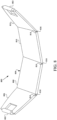
FIG. 6 is a perspective view of another example folding back plate according to some examples of the disclosure outside of the scope of protection. -
FIG. 7 is a perspective view of the folding back plate ofFIG. 6 in a folded orientation. -
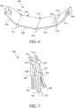
FIG. 8 is a perspective view of a back plate that can be taken apart according to some examples of the disclosure outside of the scope of protection. -
FIGs. 9 and 10 illustrate another back plate according to some examples of the disclosure. -
FIGs. 11 and 12 illustrate another back plate according to some examples of the disclosure. -
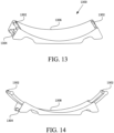
FIGs. 13 and 14 illustrate another back plate with an adjustable connector according to some examples of the disclosure. -
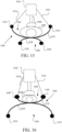
FIGs. 15 and 16 are front views of a backboard having an adult patient side and a pediatric patient size according to some examples of the disclosure. -
FIGs. 17 and 18 are front views of another backboard having an adult patient side and a pediatric patient size according to some examples of the disclosure. -
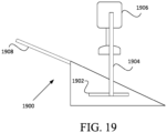
FIG. 19 is an example of a wedge-shaped backboard according to some examples of the disclosure outside of the scope of protection. -
FIG. 20 is a schematic block diagram of a mechanical compression device according to some examples of the disclosure. -
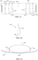
FIG. 21 is a top view of a backboard having stabilizing members according to some examples of the disclosure. -
FIG. 22 is a cross-section view of a stabilizing member according to some examples of the disclosure. -
FIG. 23 is a cross-section view of the backboard ofFIG. 21 with the stabilizing member ofFIG. 22 . -
FIG. 24 is a front view of another example of a stabilizing member according to some examples of the disclosure. -
FIG. 25 is a cross-section view of a backboard with the stabilizing member ofFIG. 24 . -
FIG. 26 is a top view of another backboard having lateral supports according to other examples of the disclosure. -
FIG. 27 is a top perspective view of the backboard ofFIG. 26 . -
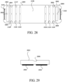
FIG. 28 is a top view of another backboard having lateral supports according to other examples of the disclosure. -
FIG. 29 is a front view of a lateral support ofFIG. 28 . -
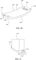
FIG. 30 is a perspective view of a backboard according to some examples of the disclosure. -
FIG. 31 is a perspective view of an end portion of a leg of a chest compression device according to some examples of the disclosure. -
FIG. 32 is a cross-section view of the leg ofFIG. 31 attached to the backboard ofFIG. 30 . -
FIG. 33 is a perspective view of one end of a backboard according to some examples of the disclosure. -
FIG. 34 is a perspective view of an end portion of a leg of a chest compression device according to some examples of the disclosure. -
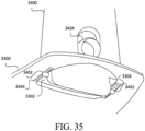
FIG. 35 is a cross-section view of the leg ofFIG. 34 attached to the backboard ofFIG. 33 . -
FIG. 36 is a perspective view of a carrying case with cushions according to some examples of the disclosure. -
FIG. 37 is a perspective view of the cushions ofFIG. 36 on a backboard according to some examples of the disclosure. -
FIG. 38 is a top view of a backboard with a cushion to support a chest compression device according to some examples of the disclosure. -
FIG. 39 is a front view of a chest compression device with the cushion ofFIG. 38 used as lateral support. -
FIG. 40 is a perspective view of a supportive structure, according to examples in the disclosure. -
FIGs. 41A-41C are front views of the supportive structure ofFIG. 40 on a backboard, according to examples in the disclosure.FIGs. 41A-41C illustrate the lateral sections of the supportive structure in three different positions. -
FIG. 42 is a top view of the supportive structure and backboard ofFIG. 41A , but without showing the patient. - Examples of the disclosure are directed to adjustable back plates or backboards for a mechanical compression device to accommodate different patient sizes or for ease of storage. As will be discussed in more detail below, examples of the disclosure includes back plates that can be folded, pieced together, or otherwise have a variable distance between connectors that attach to the legs of the chest compression device. Examples also include back plates which may have two sides to accommodate different patient sizes.
-
FIG. 1 is a front view of anexample CPR device 100 ofFIG. 1 . WhileFIG. 1 is described to illustrate a mechanical compression device, examples of the disclosure are not limited to this particular type of compression device, but may be used with any compression device. - As will be understood by one skilled in the art, the
mechanical CPR device 100 may include additional components not shown inFIG. 1 . As illustrated inFIG. 1 , aCPR device 100 may include asupport structure 104 and acentral unit 106. Thesupport structure 104 may include asupport legs 108 and abase member 110. Thesupport legs 108 and thebase member 110 each meet at ajunction 112 between thesupport leg 108 and thebase member 110. - The
support legs 108 may be configured to supportcentral unit 106 at a distance from thebase member 110. For example, if thebase member 110 is underneath the patient, who is lying on the patient's back, then thesupport leg 108 may support thecentral unit 106 at a sufficient distance over thebase member 110 to allow the patient to lay within a space between thebase member 110 and thechest compression mechanism 114, while positioning thechest compression mechanism 114 over the patient's chest. The base member, or back plate, 110 may be configured to be placed underneath the patient, for example when the patient is lying on the patient's back. - The
central unit 106 may be configured to deliver CPR chest compressions to the patient. The central 106 may include, for example, a motor-drivenpiston 116 configured to contact the patient's chest through thesuction cup 102 to provide the CPR compressions. Thecentral unit 106 may also include a number of electronic components to drive the motor-drivenpiston 116. Attached the motor-drivenpiston 116 is asuction cup 102 which adheres to the chest of the patient during chest compressions. Thesuction cup 102 can allow the motor-drivenpiston 116 to lift the chest back to a resting height, or provide a full decompression of the chest of the patient, when the motor-drivenpiston 116 is retracted from an extended position. -
FIGs. 2 and 3 illustrate aback plate 200 according to some examples of the disclosure outside of the scope of protection.Back plate 200 may be used instead ofbase member 110 discussed above to provide an adjustable back plate to accommodate different patient sizes. Theback plate 200 includes two connection rails, or connectors, 202 which are structured to attach to a leg of the mechanical compression device. For example, the leg of the mechanical compression device may have a claw-like attachment member which can attach toconnector 202. Other connection mechanisms may be utilized and examples of the disclosure are not limited to rail connectors. For example, theconnectors 202 may slide into a receptacle in the leg of the compression device to attach the leg to theback plate 200. Theconnector 202 may form part of a handle for carrying thebackboard 200. - The
back plate 200 includes an adjustableelongated portion 204 that extends along an axis between thefirst connector 202 and thesecond connector 202. Theelongated portion 204 may be telescoping and include afirst portion 206 that is structured to receive or slide relative to asecond portion 208. That is, thesecond portion 208 can slide within a compartment of thefirst portion 206. Although not shown, in some example,multiple portions 206 may be provided that can slide within compartments of each other. For example, a middle portion may slide within compartments of two outside portions. That is, the outside portions can either abut each other, or may be extended such that middle portion is exposed to laterally extend thebackboard 200. - A number of different stops may be provided within the
first portion 206 to select a size for theback plate 200. For example, a rescuer may release aclamp 210 which can allow thesecond portion 208 to slide in or out of thefirst portion 206. The rescuer may re-engage the clamp to set the length of theback plate 200 in one ormore slots 212. The clamp, for example, may engage with aslot 212 or other type of recess to lock thesecond portion 208 relative to thefirst portion 206. Other locking mechanisms may be used as well and examples of the disclosure are not limited to a clamp style locking mechanism. -
FIG. 2 illustrates theback plate 200 in the most extended position, whileFIG. 3 illustrates theback plate 200 in a contracted position. Theback plate 200 can be expanded or contracted between any of the two positions, such that theelongated portion 204 has a variable distance between theconnectors 202. -
FIGs. 4 and 5 illustrate an example outside of the scope of protection of aback plate 400 which may be folded to save space during transportation. Theback plate 400 can include twoconnectors 402, similar toconnectors 202 discussed above.Connectors 402 are not limited to rails, but may be any type of connection mechanism that can engage with a leg of a mechanical compression device. Theconnector 402 may form part of a handle for carrying thebackboard 400. - The
back plate 400 includes anelongated portion 404 that extends between theconnectors 402. Theelongated portion 404 includes twosegments sections elongated portion 404 to be folded so that one of the segments of 406 or 408 is on top of theother segment - In some examples, an
optional connector 402 may be added to either one ofsegments FIG. 4 , theoptional connector 402 is shown as part ofsegment 406 located near thehinge 410. Theoptional connector 402 can allow the backboard to be utilized with the mechanical compression device when folded. -
FIG. 5 illustrates theback plate 400 in a folded configuration, which can allow for easier storage during transportation and theback plate 400 takes up less physical space during transportation. - Examples of the disclosure outside of the scope of protection are not limited to a back plate with two segments. As illustrates in
FIGs. 6 and 7 , aback plate 600 can include a number of different segments. Although four segments are shown in this example, three segments or more than four segments could be included in theback plate 600 to offer variety in the sizes theback plate 600 may be folded into. Theback plate 600 includesconnectors 602 similar toconnectors connector 602 may form part of a handle for carrying thebackboard 600. - An
elongated portion 604 ofback plate 600 is composed of foursegments Segments connectors 602, andsegment 606 is attached tosegment 608 by one or more hinges 614.Segment 608 is also connected tosegment 610, which is then connected tosegment 612, each by hinges 614. - The
back plate 600 may be foldable in different configurations for use with different sized patients. For example, in one configuration,segment 610 can be folded via thehinge 614 to be on top ofsegment 608, whilesegment 612 is folded oversegment 610. That is, this configuration would result in anelongated portion 604 which is two segments wide,segments back plate 600 is unfolded in its entirety to be four segments wide. - Either or both of
segments connector 602 on an edge to allow for a three segment wide backplate 600.FIG. 6 , for example illustrates anoptional connector 602 as part ofsegment 610 along the edge ofsegment 610 that attaches via thehinge 614 tosegment 612.Segment 612 can be folded by thehinge 614 to be under thesegment 610 and a leg of the mechanical compression device can attach both to theconnector 602 attached tosegment 606 and theconnector 602 attached tosegment 610 to provide a backboard that is three segments wide. If five or more segments are provided, theback plate 600 may be folded to be in any number of different widths suitable for patients of different sizes, especially when each segment includes aconnector 602. - Although hinges are illustrated above with respect to
backboards -
FIG. 8 illustrates another example of aback plate 800 outside of the scope of protection, which can includeconnectors 802 similar toconnectors connector 802 may form part of a handle for carrying thebackboard 800. Rather than having segments attached byhinges 614, as illustrated inFIG. 6 , theelongated portion 804 may have a variable distance between theconnectors 802 by havingmultiple segments segment 806 may include aconnector 802 on one edge and arecess 814 on another edge to connect to acorresponding protrusion 816 onsegment 808.Segment 808 may include arecess 814 on the opposite edge, which can receive aprotrusion 816 of a connecting segment. - Multiple back plate segments may be combined together, so additional segments may be provided, with one edge having a
recess 814 and the other edge having anotch 816.FIG. 8 illustrates four segments, but additional or fewer middle segments may be provided similar tosegments segment 806 may connect directly tosegment 812 to create a two segment wide back plate. The back plate segments can be disassembled for storage and reassembled to the correct size during mechanical CPR. Although a dovetail connection is shown inFIG. 8 , any type of fastener to connect the segments together may be used. For example, a weaver rail connection may be used, or a stud and tube connection, as well as other types of fasteners. -
FIGs. 9 and 10 illustrate another example of abackboard 900 according to some examples of the disclosure.Backboard 900 includes twoconnectors elongated portion 906 extending between the twoconnectors elongated portion 906 may have a variable distance like any of the backboards discussed above in some examples. - The two
connectors central axis 908 of thebackboard 900. This direction is also indicated byarrow 910 inFIG. 9 . When not in use, theconnectors elongated portion 906. During use, theconnectors - In the examples illustrated in
FIGs. 9 and 10 , two possible positions connection positions for theconnectors connector 902 which can allow thecompression mechanism 114 to sit closer to a smaller patient's chest relative to theelongated portion 906. A second position is illustrated byconnector 904 which is a higher position to allow the mechanical compression device to accommodate a patient with a great chest height since thecompression mechanism 114 will sit higher relative to theelongated portion 906. When not in use, theconnectors elongated portion 906 - A stopper or other locking mechanism, such as a clamp, may be provided to lock the
connectors connectors FIGs. 9 and 10 , any number of connection positions may be provided. As will be understood by one having ordinary skill in the art, during use theconnectors connectors -
FIGs. 11 and 12 illustrate another example of abackboard 1100 according to some examples of the disclosure. Thebackboard 1100 includesremovable connectors elongated portion 1106 include a plurality ofrecesses 1108. Although tworecesses 1108 are shown inFIG. 11 , more than two 1108 recesses may be provided. - Each of the
connectors protrusion 1110 that is structured to fit within therecesses 1108. Theconnectors backboard 1100 to accommodate different patient sizes. For example, inFIG. 11 , theconnector 1102 is positioned in thebottom recess 1108 to accommodate a smaller patient andconnector 1104 is positioned in anupper recess 1108 to accommodate a larger patient. Theconnectors backboard 1100 is not in use. - Although a dovetail connection is shown in
FIGs. 11 and 12 , any type of fastener to connect theconnectors elongated portion 1106 may be used. For example, a weaver rail connection may be used, or a stud and tube connection, as well as other types of fasteners. -
FIG. 12 illustrates anexample locking mechanism 1202 which may be used in some examples to lock theconnectors recesses 1108. In some examples, anengagement mechanism 1204 may be provided on one or both sides of theconnectors engagement mechanism 1204 for example may be a component which can be manipulated to engage thelocking mechanism 1202, such as plunger. Thelocking mechanism 1202 engages with some portion of therecesses 1108 to keep theconnectors 1102 in place within therecess 1108 during operation of a mechanical compression device. -
FIGs. 13 and 14 illustrate another example of abackboard 1300 according to some examples of the disclosure.Backboard 1300 can includemultiple connectors elongated portion 1306 that expands between theconnectors 1304 and accommodates a patient when a mechanical chest compression device is attached to one of theconnectors elongated portion 1306 may have a variable width or distance, as discussed above. -
Connector 1304 is are stationary connection points for respective legs of a mechanical compression device.Connector 1304 is provided lower relative toconnector 1302 to provide a connection point to accommodate smaller patients. When legs of a mechanical compression device are connected or attached toconnector 1304, a compression mechanism is lower and positioned closer to a top surface ofelongated portion 1306. -
Connectors 1302 are extendable relative to theelongated portion 1306. That is,connectors 1302 have a variable distance between each other. As illustrated inFIG. 13 , whenconnectors 1302 are in their retracted position, legs of the mechanical chest compression device cannot attach to theconnectors 1302 and can only attached toconnectors 1304. Whenconnectors 1302 are each extended, as illustrated inFIG. 14 , from theelongated portion 1306, respective legs of the mechanical compression device can attach or couple to theconnector 1302 to provide compressions to a chest of a patient. Generally,connectors 1302 are extended to accommodate patients with larger chest heights so that a compression mechanism of a mechanical compression device is positioned at a higher position relative to a top surface of theelongated portion 1106. - As will be understood by one skilled in the art, although not shown, in some examples the
extendable connectors 1302 can be locked relative to theelongated portion 1306 and held rigid when attached to a mechanical compression device. Any type of locking mechanism may be used, such as a clamp, to ensure that theextendable connectors 1302 are stable during mechanical CPR. In other examples, the connection and force of the mechanical compression device may keep theextendable connectors 1302 rigid and no locking mechanism is provided or needed. -
FIGs. 15 and 16 illustrate aback plate 1500 which can accommodate two different patient sizes, an adult patient and a smaller or pediatric patient.Back plate 1500 includes anadult patient side 1502 and a pediatric (or smaller)patient side 1504.FIG. 15 illustrates when theadult patient side 1502 is in use with anadult patient 1506 andFIG. 16 illustrates when thepediatric patient side 1504 is in use with a pediatric orsmaller patient 1508. - The
adult patient side 1502 can include acurved portion 1510 spanning between twoconnectors 1512 which are structured to attach tolegs 1514 of amechanical compression device 1516. Thepediatric patient side 1504 also includes acurved portion 1518 spanning between twoconnectors 1520 which are structured to attach tolegs 1514 of themechanical compression device 1516. - Each
curved portion curved portion 1510 may be more deeply curved so thepatient 1506 sits lower relative to theconnectors 1512 and themechanical compression device 1516. That is, the radius of curvature of thecurved portion 1510 can be greater than the radius of thecurved portion 1518. This can allow for apatient 1506 with a larger sternum height to receive the compressions.Curved portion 1518, on the other hand, is curved so that thepatient 1508 sits higher relative to theconnectors 1520 and themechanical compression device 1514 to allow a patient with a smaller sternum height to receive the mechanical compressions. - When the
adult patient side 1502 is in use, thepediatric patient side 1504 supports theadult patient side 1502 on a ground or other surface. Conversely, when thepediatric patient side 1504 is in use, theadult patient side 1502 supports thepediatric patient side 1504 on the ground or other surface. - Examples of the disclosure are not limited to the curve shapes shown in the
backboard 1500 inFIGs. 15 and 16 .FIGs. 17 and 18 illustrate abackboard 1700 that also includes a larger oradult patient side 1702 and a pediatric orsmaller patient side 1704. -
Backboard 1700 includes aconcave portion 1706 on theadult patient side 1702 between twoconnectors 1708 and aflat portion 1710 on thepediatric patient side 1704 between twoconnectors 1712. Similar to thebackboard 1500, theconnectors leg 1714 of amechanical compression device 1716. - In some examples, although referred to as a
flat portion 1710 on thepediatric patient side 1704, thepediatric patient side 1704 may include a convex portion with a center portion that is flat to accommodate a patient. That is, both thepediatric patient side 1704 and theadult patient side 1706 may have a curvature, and the curvature may include a flat portion. A radius of the curvature of thepediatric patient side 1704 is less than a radius of the curvature of theadult patient side 1706. In other examples, rather than a convex portion, a concave portion with a center flat portion may be provided on thepediatric patient side 1704. In some examples, theflat portion 1710 can be a convex with a radius different than the opposite side curvature radius. Similar to thebackboard 1500 discussed above, when theadult patient side 1702 is in use, thepediatric patient side 1704 supports theadult patient side 1702 on a ground or other surface. Conversely, when thepediatric patient side 1704 is in use, theadult patient side 1702 supports thepediatric patient side 1704 on the ground or other surface. - The
pediatric patient side 1704 may additionally or alternatively includeconnectors 1718 which are located on the outer edges of theflat portion 1710. If bothconnectors connectors mechanical compression device 1716 in the needed position for the smaller patient. -
FIG. 19 illustrates another example of abackboard 1900 outside of the scope of protection that can accommodate different patient sizes.Backboard 1900 may be wedge-shaped to facilitate a smooth body position for the patient since lifting the patient chest only may lead to reduced efficacy of the CPR being administered. - The
backboard 1900 may be shaped so that a first side of thebackboard 1900 provides a first angled incline and the second side of thebackboard 1900 provides a second angled incline, the second angled incline being greater than the first angled incline to accommodate a smaller patient. The second side allows a smaller patient to be higher and therefore closer to the chest compression mechanism. - The
backboard 1900 may include aconnector 1902, which may be, for example, a connector rail which can receive a claw-like attachment member of aleg 1904 of thechest compression device 1906. - Rather than having two sides, the
backboard 1900 may be longer and have alonger connector 1902 so that a patient can be placed at the desired position along thebackboard 1900. For example, smaller patients may be placed on the higher inclined angle of thebackboard 1900 while larger patients may be placed lower on the inclined angle of thebackboard 1900. Themechanical compression device 1906 may then be connected to theconnector 1902 by thelegs 1904 at a location that corresponds to the compression point on the patient. - Any of the backboards discussed above may include a retractable or detachable head rest to accommodate a head of a patient and to prevent the chest from being higher than the head of the patient. Such a retractable or
detachable head rest 1908 is illustrated inFIG. 19 , but as will be understood by one skilled in the art, could be included with any one ofbackboard 800, backboard 1000, andbackboard 1900. Additionally or alternatively, thebackboards backboard 800, backboard 1000, and backboard 1900 may be collapsible or otherwise contractible into a smaller footprint for ease of transportation and storage. For example, if thebackboard backboard 1500, backboard 1700, orbackboard 1900 may be telescoping to reduce the length of the backboard when not in use. -
FIG. 20 illustrates an example schematic block diagram of amechanical compression device 2000. As will be understood by one skilled in the art, themechanical compression device 2000 may include additional components not shown inFIG. 20 . Themechanical compression device 2000 includes acontroller 2004, which may be in electrical communication with acompression member 2006, which can include a piston and a suction cup. - The
controller 2004, as will be discussed in more detail below, provides instructions to thecompression member 2006 to operate thecompression member 2006 at a number of different rates, waveforms, depths, heights, duty cycles or combinations thereof that change over time. Example chest and/or abdomen manipulation instructions or protocols include compressing a chest and/or abdomen and decompressing and/or expanding of a chest and/or abdomen of a patient. - The
controller 2004 may include aprocessor 2008, which may be implemented as any processing circuity, such as, but not limited to, a microprocessor, an application specific integration circuit (ASIC), programmable logic circuits, etc. Thecontroller 2004 may further include amemory 2010 coupled with theprocessor 2008.Memory 2010 can include a non-transitory storage medium that includesprograms 2012 configured to be read by theprocessor 2008 and be executed upon reading. Theprocessor 2008 is configured to execute instructions frommemory 2010 and may perform any methods and/or associated operations indicated by such instructions.Memory 2010 may be implemented as processor cache, random access memory (RAM), read only memory (ROM), solid state memory, hard disk drive(s), and/or any other memory type.Memory 2010 acts as a medium for storingdata 2014, such as instructions for thecompression member 2006 based on a type of suction cup attached, event data, patient data, etc., computer program products, and other instructions. -
Controller 2004 may further include areader 2016. Thereader 2016 can receive a signal or otherwise sense a type of backboard and orientation of a backboard through anidentifier 2018. Thereader 2016 may be, for example, an RFID reader, a quick response (QR) code reader, or may receive an input signal from an attached backboard. - The
controller 2004 may be located separately from thecompression member 2006 and may communicate with thecompression member 2006 through a wired or wireless connection. Thecontroller 2000 also electrically communicates with auser interface 2020. As will be understood by one skilled in the art, thecontroller 2004 may also be in electronic communication with a variety of other devices, such as, but not limited to, a communication device, another medical device, etc. - Operations of the
medical device 2000 may be effectuated through theuser interface 2020. Theuser interface 2020 may be external to or integrated with a display. For example, in some examples, theuser interface 2020 may include physical buttons located on themedical device 2000, while in other examples, theuser interface 2020 may be a touch-sensitive feature of a display. Theuser interface 2020 may be located on themedical device 2000, or may be located on a remote device, such as a smartphone, tablet, PDA, and the like, and is also in electronic communication with thecontroller 2004. In some examples,controller 2004 can receive a rate, a waveform, and/or depth input from theuser interface 2020 and, responsive to the rate, the waveform, and/or depth input, cause thecompression member 2006 to move to adjust the rate, waveform, and/or depth of the compression, decompression, or expansions during a session. - The backboard, such as any one of the backboards discussed above, may have one or
more identifiers 2018, which may be an RFID tag, a QR code on the suction cup, a chip, such as, but not limited to, an erasable programmable read-only memory, or anyother identifier 2018 that has a proprietary code or other identification which can be read by thereader 2016. Theidentifier 2018 may be located anywhere on or in the backboard. The backboard may also includemultiple identifiers 2018 to indicate a type and orientation of an attached backboard. - For example, an
identifier 2018 may be an RFID tag embedded in both an adult patient side and a pediatric patient side of the backboard, and thereader 2016 can read the RFID tag that is closest, telling thecontroller 2004 what orientation the backboard is in and setting a protocol based on the orientation. Additionally or alternatively, the connectors of the backboard may include a chip orother identifier 2018 which is electrically connected to thereader 2016 by the connectors. That is, the properties of the circuit created by the electrical connection between theidentifier 2018 and thereader 2016 can instruct thecontroller 2004 what orientation the backboard is in. A QR code may be printed on each side of the backboard and can be readable by thereader 2016. Depending on which QR code is read by thereader 2016 would indicate which orientation the backboard is in. - Additionally or alternatively, one or
more sensors 2022 may be attached to mechanical components of themechanical compression device 2000 and thecontroller 2004 can determine what type of backboard is attached based on the position of components of themechanical compression device 2000. For example, legs of mechanical compression device may be attached to a central unit by hinges, as illustrated inFIG. 1 . The one ormore sensors 2022 can determine the angle of the hinge and from that information determine what type of backboard is attached to the legs. For example, if the angle is greater than a threshold, thecontroller 2004 may determine the backboard is an adult orientation, whereas if the angle is less than a threshold, thecontroller 2004 may determine the backboard is in the pediatric orientation. - Additionally or alternatively, the connector of the backboard that attaches to the leg of the mechanical compression device may have a particular width or diameter to indicate what orientation the backboard is in. For example, the adult side of the backboard may have a wider connector than the pediatric side of the backboard. A
sensor 2022 may be provided in the attachment mechanism of the leg of themechanical compression device 2000 and based on how wide or narrow the claw is to engage the connector can inform thecontroller 2004 which orientation the backboard is in. - The
memory 2010 can store a number of CPR protocols that can be activated based on theidentifier 2018 read by thereader 2016. The CPR protocols may include, for example, at least one of a pediatric CPR protocol and an adult CPR Protocol. The protocol may be activated by thecontroller 2004 based on theidentifier 2018 stored on the backboard. Examples of the disclosure, however, are not limited to these types of protocols and other protocols may also be stored in thememory 2010 and activated based on theidentifier 2018 on or in the backboard. -
FIGs. 21-23 illustrate another example of abackboard 2100 that can accommodate different patient sizes. Similar to many of the backboards discussed above, backboard 2100 can include aconnection rail 2102 on opposite ends of thebackboard 2100. The connection rails 2102 are structured receive a leg of a chest compression device to attach the chest compression device to thebackboard 2100. For example, an end portion of legs of the chest compression device may include a claw-like member that can grab or attach onto the connection rails 2102. However, other types of connections may be used as well. -
Backboard 2100 can include a number ofdifferent apertures 2104 that are structured or shaped to receive stabilizingmembers 2106, which are illustrated inFIGs. 22 and 23 . WhileFIG. 21 illustrates threeapertures 2104 on each side of thebackboard 2100, examples of the disclosure are not limited to sixapertures 2104 and any number of apertures may be provided in thebackboard 2100, as long as an equal number ofapertures 2104 are provided on each side of the backboard between apatient receiving section 2108 of the backboard. Further, whileFIG. 21 illustrates theapertures 2104 having a support beam in the middle, examples of the disclosure are not limited to these types ofapertures 2104 in thebackboard 2100. A shorter length aperture with no support beam may be provided within thebackboard 2104 to receive the stabilizingmembers 2106. - During use, two stabilizing
members 2106, such as stabilizingmembers 2106 shown inFIG. 22 , can be inserted intocorresponding apertures 2104 on each side of thebackboard 2100. The stabilizingmembers 2106 may include awedge shape 2202 with aprotrusion 2204 structured to be received in theapertures 2104 of thebackboard 2100. The stabilizingmembers 2106 may be made of any stiff or semi-stiff material, such as, but not limited to, foam or plastic. WhileFIG. 22 shows a side view of the stabilizingmember 2106, as will be understood by one skilled in the art, the stabilizingmember 2106 may have twoprotrusions 2204 to accommodate anaperture 2104 with a support beam in the middle. The wedge-shape of the stabilizingmember 2106 allows theprotrusion 2204 to fit within the aperture such that the wedge portion of the stabilizingmember 2106 is generally vertical relative to thebackboard 2100. Further, stabilizingmembers 2106 may be any shape, such as a flat rectangular or square shape, that can attach to theapertures 2104, and is not limited to a wedge-shaped 2202 stabilizingmember 2106. As long as the stabilizingmembers 2106 include anarrower protrusion 2204 with a wider body, the stabilizingmembers 2106 will be capable of standing up within theapertures 2104 to laterally stabilize a patient 22. - In some examples,
markers 2110 may be painted or printed on thebackboard 2100 to assist a rescuer in placing the stabilizingmembers 2106 in correspondingapertures 2104 on each distal end of thebackboard 2100. Themarkers 2110 can help a rescuer to ensure the stabilizingmembers 2106 are located at the same location on each distal end of thebackboard 2100 to provide balance of the patient on thepatient receiving section 2108 of thebackboard 2100 and to help center apatient 2302 under a piston, such aspiston 116. - For example, if
markings 2110 are provided, the innermost apertures 2104 may include asingle dot marker 2110 to indicate a very small or narrow patient, while themiddle apertures 2104 includes twodot markers 2110 and theoutside apertures 2104 include threedot markers 2110 to show an increase in patient size. This can assist a rescuer to ensure that a patient is located in the middle of thebackboard 2100 for compressions and that there is equal spacing between the stabilizingmembers 2104 and the connection rails 2102. Whilemarkers 2110 are shown as dots inFIG. 21 , examples of the disclosure are not limited to dotmarkers 2110 and may be any type of marking to indicate the spacing of the stabilizingmembers 2106, such as numbers or words. -
FIG. 24 illustrates another example of a stabilizingmember 2400 according to some examples of the disclosure. Stabilizingmember 2400 can include, similar to stabilizingmember 2106, a wedge-shape 2402 and aprotrusion 2404. Similar to stabilizingmember 2106, the stabilizingmember 2400 does not have to be wedge-shape, but can be any shaped member with aprotrusion 2404 structured to fit within a corresponding hole or aperture of a backboard. Stabilizingmember 2400, however, may include aconnection rail 2406 that can attach or connect to a leg of a corresponding compression device. - Stabilizing
member 2400 can fit within theapertures 2104 ofFIG. 21 , or, in some examples, theapertures 2502 can be angled within thebackboard 2500 so the stabilizing member can attach to a leg of the compression device. The rail orshaft 2406 of the stabilizingmember 2400 may be positioned to be above theconnection rail 2102 of the backboard in some examples. In other examples, the stabilizingmember 2400 can be longer so that the rail orshaft 2406 of the stabilizingmember 2400 extends out past theconnection rail 2102. Further, although only two apertures are shown inFIG. 25 in thebackboard 2500, multiple apertures may be provided. If the stabilizingmember 2400 is connected or coupled with an inner aperture for a smaller patient, the legs of the compression device may connect to theconnection rail 2102 of the backboard rather than theshaft 2406 of the stabilizingmember 2400. -
FIGs. 26 and 27 illustrate another example of abackboard 2600 according to some examples of the disclosure. In this example, stabilizingmembers 2602 are provided directly within thebackboard 2600. WhileFIG. 26 illustrates six stabilizingmembers 2602, three on each distal end of thebackboard 2600, examples of the disclosure are not limited to this number of stabilizingmembers 2602. Any number of stabilizingmembers 2602 may be provided. - Similar to other backboards discussed above, backboard 2600 includes
connection rails 2604 to connect to legs of a compression device and apatient receiving area 2606 located in the center of thebackboard 2600. - Each of the stabilizing
members 2602 may be rotatably connected to thebackboard 2600. For example, the stabilizingmembers 2602 may be rotatably connected to thebackboard 2600 by ahinge 2608 or any other rotation means. The stabilizingmembers 2602 may each have ahandle 2610 either cut into the stabilizing member or some type of pull or strap for a rescuer to grab and rotate the stabilizing member into a vertical position that is generally perpendicular to the surface of thebackboard 2600. Thehinge 2608 may be a locking hinge that locks the stabilizingmember 2602 into the generally vertical position. Other locking mechanisms may also be provided, such as a clamp. In some examples, no handle is provided, but a rescuer may push on the bottom of the stabilizingmember 2602 to rotate the stabilizingmember 2602 into a generally vertical position. The stabilizingmember 2602 can be locked into the generally vertical position using any known locking mechanism. - Similar to
backboard 2100,markers 2612 may be provided to help assist a rescuer in confirming that corresponding stabilizingmembers 2602 are lifted on each side of thebackboard 2600.Markers 2612 may be any type of marker to designate corresponding stabilizingmembers 2602 on each side of thebackboard 2600. -
FIG. 27 illustrates a perspective view of thebackboard 2600 with two of the stabilizingmembers 2602 lifted into the generally vertical position. The stabilizingmembers 2602 stabilize a patient between the stabilizingmembers 2602 when a compression device is attached to thebackboard 2600 to help center a patient under apiston 116 during chest compressions. The stabilizingmembers 2602 can prevent the patient from sliding laterally along thebackboard 2600 during operation of the compression device. - In another example,
FIG. 28 illustrates abackboard 2800 with removable stabilizingmembers 2802.Backboard 2800 includes a number of features similar to those shown inFIG. 21 and as such, those features are shown with the same reference numbers are those discussed above. For example, similar tobackboard 2100, backboard 2800 can include a number ofapertures 2104 to receive stabilizing members,markers 2110, apatient receiving portion 2108, and connection rails 2102. -
FIG. 29 illustrates the stabilizingmember 2802. The stabilizingmember 2802 may include one ormore protrusions 2902 that are structured to be accommodated within theapertures 2104. - In the example backboard 2800, the stabilizing
members 2802 may be stored directly within thebackboard 2800 itself, rather than within a carrying case for the backboard. For example, the stabilizingmember 2802 may fit within an aperture of the backboard. WhileFIG. 28 shows the stabilizingmembers 2802 stored at the end of thebackboard 2800 near the connection rails 2102, the stabilizingmembers 2802 may also be stored within thepatient receiving portion 2108 in some examples. - An aperture may be provided within the
backboard 2800 to receive the stabilizingmember 2802, and one ormore grooves 2804 may be located within the center of thebackboard 2800, as shown by dashed lines, to receive theprotrusions 2902 when the stabilizingmember 2802 is stored within thebackboard 2800 itself. The stabilizingmember 2802 may include ahandle 2806 to assist with a rescuer pulling the stabilizing member out of thebackboard 2800 and placing into theapertures 2104 to stabilize the patient. -
FIG. 30 illustrates another example backboard 3000 according to some examples of the disclosure.Backboard 3000 includes apatient receiving surface 3002 and abottom surface 3004 opposing thepatient receiving surface 3002. Thebackboard 3000 includes twoprotrusions 3006 defining an opening orgap 3008 to accommodate a leg of a compression member on each distal end of thebackboard 3000. Each of theprotrusions 3008 include a number ofprojections 3010 on thebottom 3004 of thebackboard 3000. As will be discussed in more detail below, theprojections 3010 on eachprotrusion 3008 is structured to attach to a leg of a compression device, such asleg 108 ofcompression device 100 to the backboard. That is, rather than a leg connecting to a connection rail, as discussed above in some examples, the leg of the compression device can connect or attached to theprojections 3010. -
FIG. 31 illustrates an example bottom portion of aleg 3100 of a compression device that can attach to thebackboard 3000. As will be understood by one skilled in the art, theleg 3100 may be used with thecompression device 100 illustrated inFIG. 1 , rather than theleg 108 shown inFIG. 1 . -
Leg 3100 can include abase 3102 on each side of theleg 3100. Each base can include a number of receivers, orprotrusions 3104. Theprotrusions 3104 are spaced apart to accommodate aprojection 3010 of thebackboard 3000. While a side view of theleg 3100 is shown, eachbase 3102 of each leg includesprotrusions 3104. Theprotrusions 3104 may be different heights or may be the same height. - The
projections 3010 can be received between or around theprotrusions 3104, to create a hook and receiver connection to attach thebaseboard 3000 to theleg 3100, as shown inFIG. 32. FIG. 32 illustrates a cross-section view of thebackboard 3000 connected to theleg 3100 to illustrate the connection of thebackboard 3000 to thebase plate 3102 by theprotrusions 3104. Any one of theprojections 3010 of theprojection 3008 may be received between theprojections 3010 andprotrusions 3104 of theleg 3100. This can allow the space or width between thelegs 3100 of the back compression device to move closer together or further from each other to accommodate different patient sizes. The different widths of thelegs 3100 may also help stabilize a patient during chest compressions. - In some examples, the
projections 3010 may be spaced such that both of theprotrusions 3104 can fit between twoprojections 3010. Aprojection 3010 may fit between the space of theprotrusions 3104, providing a number of different connection points and variability in the width between thelegs 3100. That is, thelegs 3100 are able to adjust laterally with respect to thebackboard 3000 to accommodate different patient sizes. When performing compressions with a compression device, theprojections 3010 and theprotrusions 3104 work together to prevent movement of the backboard relative to thelegs 3100 of the compression device. -
FIG. 33 illustrates a distal end of an alternative backboard 3320. As will be understood by one skilled in the art, the other distal end of the backboard 3320 would be identical. The backboard 3320 includes an opening 3322 on each side of the backboard to receive a leg of the compression device. The opening 3322 is defined by the distal end of the backboard 3320. - The opening 3322 can include a number of evenly spaced grooves 3326. The grooves 3326 may be formed by a number of projections with a divot between the projections. The grooves 3326 are structured to accommodate spring-loaded
shafts 3402 of aleg 3400, which is illustrated inFIG. 34 . While only asingle leg 3400 is shown, the other leg of the compression device would have the same features. - Though
grooves 3304 are shown in thebackboard 3300, examples of the disclosure are not limited togrooves 3304 and may be any member than can prevent movement of aleg 3400. For example, rather thangrooves 3304, a number of protrusions could be provided on each side of theopening 3302, similar to those discussed above inFIG. 30 . Further, thegrooves 3304, or any other means, are mirrored on opposite sides of theopening 3302. That is, there is acorresponding groove 3304 or other means on one side of theopening 3302 directly opposite the other side of theopening 3302. -
FIG. 34 illustrates anexample leg 3400 that may be used with thecompression device 100 instead ofleg 108, for example, to attach thecompression device 100 to thebackboard 3300. Further,leg 3400 is just one example of many type of legs that may be used with thebackboard 3300. Theleg 3400 can include two opposing spring-loadedshafts 3402. Springs (not shown) can be attached to theshafts 3402 and arelease ring 3404. When pulling upward on therelease ring 3404, theshafts 3402 are retracted into theleg 3400 to allow theleg 3400 to enter theopening 3302. - The spring-loaded
shafts 3402 are provided on anend 3406 of theleg 3400 that is structured to fit within theopening 3302. The portion of theleg 3400 above theend 3406 is wider than the opening 3322 so that only theend 3406 can fit within theopening 3302. Theshafts 3402 extend beyond theend 3406 such that theend 3406 would not fit within theopening 3302 unless theshafts 3402 are retracted. This prevents theleg 3400 from disconnecting from thebackboard 3300 during use of the compression device. -
FIG. 35 illustrates a bottom perspective view of theleg 3400 attached to the backboard 3320 according to some examples of the disclosure. Therelease ring 3404 is lifted or pulled to retract theshafts 3402 into the leg so the leg can be inserted into the opening 3322. As can be seen inFIG. 35 , the lower portion of theleg 3400 is structured to be just wide enough to fit within theopening 3302. Once theleg 3400 is placed in the opening, thering 3404 can be released and theshafts 3402 can be protrude to engage with thegrooves 3304 of thebackboard 3300. Theleg 3400 is now connected to the backboard 3320 and cannot be removed without pulling therelease ring 3404 to retract theshafts 3402. - If
grooves 3304 are provided, then thelegs 3400 can move along thegrooves 3304 within theopening 3302 until at a desired position. Thelegs 3400 can be locked to aparticular groove 3304 using any locking means, such as an activator. Alternatively, thegrooves 3304 may be deep enough that the legs must be positioned at their desired location with theshafts 3402 retracted, and then once theshaft 3402 is within a particular groove or protrusion, theleg 3400 is immobile. Theopening 3302,grooves 3304, andshafts 3402 all work in conjunction to allow thelegs 3400 to laterally slide relative to thebackboard 3300 to accommodate different patient widths and chest heights and to set the legs at the most desirable location for the compression device and the patient. - The edges of the
legs 3400 around theshafts 3402 may be a replaceable rubber part that can seal the shaft bearings from intakes of liquid or dust during use or cleaning of thelegs 3400. - Additionally or alternatively to the example backboards discussed above, in some examples, cushions or support from a carrying case for the compression device may be used to laterally support a patient on the backboard. The cushions may be used with any of the above discussed backboards, or with a backboard that is not adjustable, such as
backboard 110 discussed above. -
FIG. 36 illustrates an example of anopen carrying case 3600 for a chest compression unit. The carryingcase 3600 may includecushions 3602 for carrying components of the compression unit, such as asuction cup 3604 and/or aspare battery 3608. Thecushions 3602 may be connected by an elongated flexible portions 3610 that can be folded, as seen inFIG. 36 . Thecushions 3602 may be made of any suitable semi-stiff material, such as plastic, silicone, or foam, that can return to its original shape after use with a patient. For example, a patient may be wider than the elongated portion 3610 and may lay on the edges of thecushions 3602 in some situations. Thecushions 3602 can be hollow or may have a bottom portion that can provide rigidity. - During use of the compression device, the
cushions 3602, connected by the elongated portion 3610, can be removed from the carryingcase 3600 and placed on abackboard 110, as shown inFIG. 37 . Thecushions 3602 can provide lateral support to a smaller patient to prevent the patient from sliding. Even if a patient is laying on or compressing the edges of thecushions 3602, thecushions 3602 can still prevent the patient from sliding laterally relative to the backboard and can help ensure adequate positioning of thepiston 116. In configurations, thesuction cup 3604 may be used as a support, for example, when positioned as illustrated inFIG. 37 . - The
cushions 3602 and elongated portion 3610 may include a non-slip material and be placed directly on thebackboard 110, or thecushions 3602 may attach to the backboard and/orlegs 108 via straps, hook and loop fasteners, hooks, or any other means, to help prevent the patient and cushions from sliding during use of the compression device. - In some examples, the elongated portion 3610 may be stiff or generally inflexible. In such examples, the cushions may fold relative to the elongated portion 3610 so that the
cushions 3602 rest on top of the elongated portion when in the carryingcase 3600 or may be folded out during use on thebackboard 110 with the elongated portions 3610 spanning between the twocushions 3602. - In another example, the
cushions 3602 may attach to a protrusion (not shown) within the carrying case by a holder, as shown inFIG. 36 , which may be the same width and thickness as aleg 108 of thecompression device 100. The holder can attach to theleg 108 of the compression device to provide lateral support for a patient. - As another example of a carrying case cushion,
FIG. 38 illustrates acushion 3800 that is the general shape of thebackboard 110. Thecushion 3800 inFIG. 38 is illustrated as slightly larger than the backboard, but could also be slightly smaller than the backboard in some examples. In configurations, the cushion may be, for example, inflatable, allowing the user to inflate the cushion to a higher or lower level to accommodate the patient's size. During transport of thechest compression device 100, thecushion 3800 can be placed on top of thebackboard 110 and have an opening or other cut-out 3802 to accommodate the upper portion of thechest compression device 100, including thesupport structure 104 and thecentral unit 106. For example, thelegs 108 may be folded byhinges 3804 relative to thecentral unit 106 and thesupport structure 104. Thecompression device 100 may be placed within theopening 3802 of the cushion with the foldedlegs 108. Thebackboard 110,cushion 3800, andchest compression device 100 can then be placed inside a carrying case. - During operation of the
chest compression device 100, as shown inFIG. 39 , thecushion 3800 can remain on the upper surface of thebackboard 110 and asmaller patient 3900 can be placed within theopening 3802 to provide lateral support during compressions. The cushion may be made of anti-slip material or may include a fastener, such as, but not limited to, a strap, hook and loop fastener, clips, etc., to attach the cushion to thebackboard 110 and/or thelegs 108. Thecushion 3800 may be positioned differently than what is illustrated. -
FIG. 40 is a perspective view of asupportive structure 4002, according to examples in the disclosure outside the scope of protection. As illustrated inFIG. 40 , thesupportive structure 4002 may include amiddle section 4012, afirst lateral section 4014 on a first end of themiddle section 4012, and asecond lateral section 4016 on a second end of themiddle section 4012. Each of themiddle section 4012, thefirst lateral section 4014, and thesecond lateral section 4016 are substantially rigid. As used in this context, "substantially rigid" means largely or essentially stiff and not pliant, without requiring perfect inflexibility. Afirst junction 4018 between themiddle section 4012 and thefirst lateral section 4014 is flexible to permit thefirst lateral section 4014 to pivot relative to themiddle section 4012. Asecond junction 4020 between themiddle section 4012 and thesecond lateral section 4016 is flexible to permit thesecond lateral section 4016 to pivot relative to themiddle section 4012. -
FIGs. 41A-41C are front views of thesupportive structure 4002 ofFIG. 40 on abackboard 4004, according to examples in the disclosure.FIGs. 41A-41C illustrate the lateral sections of thesupportive structure 4002 in three different positions.FIG. 42 is a top view of thesupportive structure 4002 and backboard 4004 ofFIG. 41A , but without showing thepatient 4006. - As illustrated in
FIGs. 41A-42 , thebackboard 4004 includes anelongated portion 4028 that extends along a longitudinal axis. The longitudinal axis runs left to right from the viewpoint illustrated inFIG. 42 . Theelongated portion 4028 has a first distal end and a second distal end. There are a plurality ofapertures 4022 within theelongated portion 4028. Theelongated portion 4028 and the plurality of apertures may be, for example, thebackboard 2100 andapertures 2104 depicted inFIG. 21 and described above for that drawing. Thesupportive structure 4002 has at least twoprotrusions 4010 that are structured to be received in the plurality ofapertures 4022. - The
supportive structure 4002 having a longitudinal axis, which runs left to right from the viewpoint illustrated inFIG. 42 . The longitudinal axis of thesupportive structure 4002 is substantially parallel to the axis of theelongated portion 4028. As used in this context, "substantially parallel" means largely or essentially equidistant at all points, without requiring perfect parallelism. Thesupportive structure 4002 is configured to support apatient 4006 above theelongated portion 4028. Accordingly, thesupportive structure 4002 may be particularly useful for smaller patient 4006s, including children by, for example, positioning thepatient 4006 closer to the chest compression mechanism when thesupportive structure 4002 is used with a mechanical CPR device. - As best illustrated in
FIG. 42 , theelongated portion 4028 has awidth 4024, the width being substantially perpendicular to the axis of theelongated portion 4028, in which thesupportive structure 4002 has awidth 4026. As used in this context, "substantially perpendicular" means largely or essentially at right angles, without requiring perfect perpendicularity. In configurations, thewidth 4026 of thesupportive structure 4002 half or less thewidth 4024 of theelongated portion 4028 so that thesupportive structure 4002 may be positioned in different locations on theelongated portion 4028, such as the positions labeled 4002A and 4002B inFIG. 42 . - Any of the configurations discussed above or illustrated in any of the drawings may include one or more straps connected to the backboard. The straps may assist to secure the patient, particularly a small patient such as a child, to the backboard and to help properly position the patient on the backboard. The straps may be adjustable, both in terms of length and the attachment position on the backboard. The straps may be configured to secure any or all of the patient's head, torso, arms, or wrists. In configurations, the straps may be attached instead or also to the
legs 108 of theCPR device 100. Additional fixation or positioning methods or features may also be used. - Instead of or in addition to any of the configurations discussed above, a high-friction rubber bag containing a material that makes the bag shape change may be used between the patient and the back plate to help properly position the patient. The material in the sealed, high-friction rubber bag may be, for example, flour or other materials with similar function, meaning the material in the bag may be adjusted, or moved, to adapt to the patient's size and shape.
- For purposes of this description, certain aspects, advantages, and novel features of the examples of this disclosure are described herein. Features, integers, characteristics, compounds, chemical moieties or groups described in conjunction with a particular aspect, configuration, or example of the disclosure are to be understood to be applicable to any other aspect, configuration or example described herein unless incompatible therewith. All of the features disclosed in this specification (including any accompanying claims, abstract and drawings), and/or all of the steps of any method or process so disclosed, may be combined in any combination, except combinations where at least some of such features and/or steps are mutually exclusive. The disclosure is not restricted to the details of any foregoing examples. The disclosure extends to any novel one, or any novel combination, of the features disclosed in this specification (including any accompanying claims, abstract and drawings), or to any novel one, or any novel combination, of the steps of any method or process so disclosed.
- Although the operations of some of the disclosed methods are described in a particular, sequential order for convenient presentation, it should be understood that this manner of description encompasses rearrangement, unless a particular ordering is required by specific language. For example, operations described sequentially may in some cases be rearranged or performed concurrently. Moreover, for the sake of simplicity, the attached figures may not show the various ways in which the disclosed methods can be used in conjunction with other methods.
- As used herein, the terms "a", "an", and "at least one" encompass one or more of the specified element. That is, if two of a particular element are present, one of these elements is also present and thus "an" element is present. The terms "a plurality of" and "plural" mean two or more of the specified element. "Generally" or "approximately" as used herein means a variance of 10%.
- As used herein, the term "and/or" used between the last two of a list of elements means any one or more of the listed elements. For example, the phrase "A, B, and/or C" means "A," "B," "C," "A and B," "A and C," "B and C," or "A, B, and C."
- As used herein, the term "coupled" generally means physically coupled or linked and does not exclude the presence of intermediate elements between the coupled items absent specific contrary language.
- Additionally, this written description makes reference to particular features. It is to be understood that the disclosure in this specification includes all possible combinations of those particular features. Where a particular feature is disclosed in the context of a particular aspect or example, that feature can also be used, to the extent possible, in the context of other aspects and examples.
- Also, when reference is made in this application to a method having two or more defined steps or operations, the defined steps or operations can be carried out in any order or simultaneously, unless the context excludes those possibilities.
- Although specific examples of the disclosure have been illustrated and described for purposes of illustration, it will be understood that various modifications may be made without departing from the scope of the disclosure.
Claims (15)
- A backboard (1500) for a chest compression device (1516), the backboard comprising:a first side (1502) structured to accommodate an adult-sized patient at a first distance from a support surface when attached to the chest compression device in a first orientation; anda second side (1504) structured to accommodate a pediatric-sized patient at a second distance from the support surface when attached to the chest compression device in a second orientation, the second distance being greater than the first distance;wherein the first orientation corresponds to the second side interfacing with the support surface, and the second orientation corresponds to the first side interfacing with the support surface.
- The backboard of claim 1, in which the first side includes a first attachment point (1512) and a second attachment point (1512), and in which the second side includes another first attachment point (1520) and another second attachment point (1520), wherein the first attachment point (1512) of the first side is structured to attach a first leg of the chest compression device to the backboard when in the first orientation, wherein the second attachment point (1512) of the first side is structured to attach a second leg of the chest compression device to the backboard when in the first orientation, wherein the another first attachment point (1520) of the second side is structured to attach the first leg of the chest compression device to the backboard when in the second orientation, wherein the another second attachment point (1520) of the second side is structured to attach the second leg of the chest compression device to the backboard when in the second orientation.
- The backboard of claim 1 or 2, wherein the first side has a curved portion with a first radius of curvature, and the second side has a curved portion with a second radius of curvature that is different from the first radius of curvature.
- The backboard of any of claims 1 to 3, the backboard including a connector rail structured to couple the backboard to the chest compression device.
- The backboard of any of claims 1 to 4, further comprising a retractable headrest.
- The backboard of any of claims 1 to 5, wherein the first side is concave and the second side includes a flat section (1710) to accommodate the pediatric-sized patient.
- The backboard of any of claims 1 to 6, further comprising an identifier configured to identify the backboard to the chest compression device.
- The backboard of claim 7, wherein the identifier indicates a type and orientation of an attached backboard.
- The backboard of claim 7 or 8, wherein the identifier comprises proprietary code or other identification which can be read by a reader of a chest compression device.
- The backboard of any of claims 1 to 9, wherein the second side is configured to support the first side at the first distance from the support surface when the first side is attached to the chest compression device in the first orientation, and wherein the first side is configured to support the second side at the second distance from the support surface when the second side is attached to the chest compression device in the second orientation.
- A chest compression device, comprising:a chest compression member;a backboard according to any of claims 1-10; anda controller configured to determine an identification of the backboard and adjust the chest compression member based on the identification.
- The chest compression device of claim 11, wherein the backboard includes a first identification component identifying the first orientation associated with the first side of the backboard and a second identification component identifying the second orientation associated with the backboard, and the controller is configured to received one of the first orientation or the second orientation from the backboard and control the chest compression member based on the received orientation.
- The chest compression device of claim 12, wherein the first identification component is located in a first connector associated with the first side of the backboard, the first connector configured to attach to a leg of the chest compression device when the backboard is the first orientation, and wherein the second identification component is located in a second connector associated with the second side of the backboard, the second connector configured to attach to the leg of the chest compression device when the backboard is in the second orientation.
- The chest compression device of claim 13, wherein the controller is configured to determine the identification of the backboard based on a characteristic of a first connector or a second connector.
- The chest compression device of claim 13 or 14, wherein the characteristic includes at least one of an angle of a leg of the chest compression device connected to a respective connector of the backboard or a size of an anchoring point of the respective connector.
Priority Applications (1)
| Application Number | Priority Date | Filing Date | Title |
|---|---|---|---|
| EP25162310.4A EP4541337A3 (en) | 2020-10-29 | 2021-10-29 | Adjustable back plate for mechanical compression device |
Applications Claiming Priority (2)
| Application Number | Priority Date | Filing Date | Title |
|---|---|---|---|
| US202063107184P | 2020-10-29 | 2020-10-29 | |
| US202163158800P | 2021-03-09 | 2021-03-09 |
Related Child Applications (1)
| Application Number | Title | Priority Date | Filing Date |
|---|---|---|---|
| EP25162310.4A Division EP4541337A3 (en) | 2020-10-29 | 2021-10-29 | Adjustable back plate for mechanical compression device |
Publications (2)
| Publication Number | Publication Date |
|---|---|
| EP3991710A1 EP3991710A1 (en) | 2022-05-04 |
| EP3991710B1 true EP3991710B1 (en) | 2025-03-12 |
Family
ID=78414554
Family Applications (2)
| Application Number | Title | Priority Date | Filing Date |
|---|---|---|---|
| EP21205640.2A Active EP3991710B1 (en) | 2020-10-29 | 2021-10-29 | Adjustable back plate for mechanical compression device |
| EP25162310.4A Pending EP4541337A3 (en) | 2020-10-29 | 2021-10-29 | Adjustable back plate for mechanical compression device |
Family Applications After (1)
| Application Number | Title | Priority Date | Filing Date |
|---|---|---|---|
| EP25162310.4A Pending EP4541337A3 (en) | 2020-10-29 | 2021-10-29 | Adjustable back plate for mechanical compression device |
Country Status (2)
| Country | Link |
|---|---|
| US (2) | US12409102B2 (en) |
| EP (2) | EP3991710B1 (en) |
Families Citing this family (1)
| Publication number | Priority date | Publication date | Assignee | Title |
|---|---|---|---|---|
| WO2025212848A1 (en) * | 2024-04-03 | 2025-10-09 | The Trustees Of Columbia University In The City Of New York | Systems for automated cardiopulmonary resuscitation |
Family Cites Families (19)
| Publication number | Priority date | Publication date | Assignee | Title |
|---|---|---|---|---|
| US3985126A (en) * | 1975-02-07 | 1976-10-12 | Michigan Instruments, Inc. | Patient retention and support |
| US20030127103A1 (en) * | 2002-01-09 | 2003-07-10 | Theracardia, Inc. | Removable backboard stand and method for its use |
| US7354407B2 (en) * | 2003-10-14 | 2008-04-08 | Zoll Circulation, Inc. | Methods and devices for attaching a belt cartridge to a chest compression device |
| ATE483440T1 (en) | 2006-10-20 | 2010-10-15 | Laerdal Medical As | SUPPORT FOR A CHEST COMPRESSION DEVICE |
| EP2094222A4 (en) | 2006-11-29 | 2012-11-28 | Jolife Ab | Support for a cpr apparatus |
| CN101612090B (en) | 2008-06-24 | 2011-12-07 | 刘大志 | Voice prompt manual cardiopulmonary resuscitator |
| CN102395345B (en) | 2009-04-15 | 2015-02-04 | 皇家飞利浦电子股份有限公司 | Backboard for an automated cpr system |
| DE102011014304A1 (en) | 2011-03-17 | 2012-09-20 | GS-Elektromedizinische Geräte, G. Stemple GmbH | Device for resuscitating a patient |
| CN103040602A (en) | 2011-10-12 | 2013-04-17 | 广州蓝仕威克医疗科技有限公司 | Electric control pneumatic cardio-pulmonary resuscitation machine |
| US9603772B2 (en) | 2013-02-05 | 2017-03-28 | Physio-Control, Inc. | Beam mechanical compression device |
| US9539173B2 (en) | 2013-02-05 | 2017-01-10 | Physio-Control, Inc. | Fixation of device to back plate |
| US10143619B2 (en) | 2013-05-10 | 2018-12-04 | Physio-Control, Inc. | CPR chest compression machine performing prolonged chest compression |
| US9750661B2 (en) * | 2014-02-19 | 2017-09-05 | Keith G. Lurie | Systems and methods for head up cardiopulmonary resuscitation |
| US10667989B2 (en) * | 2015-02-24 | 2020-06-02 | Jolife Ab | Cardio-pulmonary resuscitation machines with stabilizing members and methods |
| US10524123B2 (en) * | 2016-03-30 | 2019-12-31 | Zoll Medical Corporation | Establishing secure communication at an emergency care scene |
| US10507161B2 (en) * | 2016-06-06 | 2019-12-17 | Jolife Ab | Back plates for mechanical CPR Compression |
| US12285383B2 (en) * | 2016-10-21 | 2025-04-29 | Zoll Medical Corporation | System and methods for adaptive body positioning during chest compressions |
| US10849820B2 (en) | 2017-10-23 | 2020-12-01 | Physio-Control, Inc. | CPR chest compression device with lateral support pad |
| CN110731892A (en) | 2019-12-12 | 2020-01-31 | 西安交通大学医学院第一附属医院 | A cardiopulmonary resuscitation compression device for emergency critical care |
-
2021
- 2021-10-28 US US17/513,067 patent/US12409102B2/en active Active
- 2021-10-29 EP EP21205640.2A patent/EP3991710B1/en active Active
- 2021-10-29 EP EP25162310.4A patent/EP4541337A3/en active Pending
-
2025
- 2025-08-14 US US19/300,522 patent/US20250375348A1/en active Pending
Also Published As
| Publication number | Publication date |
|---|---|
| EP3991710A1 (en) | 2022-05-04 |
| EP4541337A3 (en) | 2025-06-11 |
| US12409102B2 (en) | 2025-09-09 |
| EP4541337A2 (en) | 2025-04-23 |
| US20250375348A1 (en) | 2025-12-11 |
| US20220133587A1 (en) | 2022-05-05 |
Similar Documents
| Publication | Publication Date | Title |
|---|---|---|
| US20250375348A1 (en) | Adjustable-size backboard for a mechanical cpr device | |
| KR101648205B1 (en) | Backboard for an automated cpr system | |
| JP6648890B2 (en) | Movement assist device | |
| US5882067A (en) | Rigid seat for folding invalid walker | |
| US10828216B2 (en) | Inflatable patient repositioning sheet | |
| US9066609B2 (en) | Infant patient transfer device | |
| US20210218207A1 (en) | Medical device docking station | |
| US11426620B2 (en) | Inflatable plyometric box | |
| CN108366896A (en) | Patient Trolleys and Patient Transports | |
| JP2018534119A5 (en) | ||
| US4955877A (en) | Autotransfusion bag | |
| WO2014121334A1 (en) | A mattress for ready changing of bed linen | |
| US20200315886A1 (en) | Prone-to-supine transfer mattress | |
| CN111976984B (en) | a multifunctional drone | |
| US10849820B2 (en) | CPR chest compression device with lateral support pad | |
| JP4231363B2 (en) | Back-up bed equipment | |
| US5044378A (en) | Device for distracting patients during intravenous injections | |
| CN110496008B (en) | Chronic Patient Health Care Rack | |
| KR102809325B1 (en) | Body position apparatus for Thyroid Surgery | |
| US20230063583A1 (en) | Backboard alignment of mechanical cpr device | |
| CN214343067U (en) | Patient bed turning aids for emergency care | |
| CN219595146U (en) | Postoperative walking auxiliary device | |
| CN223817813U (en) | A transfer rack and transfer cart | |
| CN214434875U (en) | A wheelchair flat car with convenient angle adjustment | |
| US11596565B2 (en) | Patient upright device |
Legal Events
| Date | Code | Title | Description |
|---|---|---|---|
| PUAI | Public reference made under article 153(3) epc to a published international application that has entered the european phase |
Free format text: ORIGINAL CODE: 0009012 |
|
| STAA | Information on the status of an ep patent application or granted ep patent |
Free format text: STATUS: THE APPLICATION HAS BEEN PUBLISHED |
|
| AK | Designated contracting states |
Kind code of ref document: A1 Designated state(s): AL AT BE BG CH CY CZ DE DK EE ES FI FR GB GR HR HU IE IS IT LI LT LU LV MC MK MT NL NO PL PT RO RS SE SI SK SM TR |
|
| STAA | Information on the status of an ep patent application or granted ep patent |
Free format text: STATUS: REQUEST FOR EXAMINATION WAS MADE |
|
| 17P | Request for examination filed |
Effective date: 20221031 |
|
| RBV | Designated contracting states (corrected) |
Designated state(s): AL AT BE BG CH CY CZ DE DK EE ES FI FR GB GR HR HU IE IS IT LI LT LU LV MC MK MT NL NO PL PT RO RS SE SI SK SM TR |
|
| STAA | Information on the status of an ep patent application or granted ep patent |
Free format text: STATUS: EXAMINATION IS IN PROGRESS |
|
| 17Q | First examination report despatched |
Effective date: 20240527 |
|
| GRAP | Despatch of communication of intention to grant a patent |
Free format text: ORIGINAL CODE: EPIDOSNIGR1 |
|
| STAA | Information on the status of an ep patent application or granted ep patent |
Free format text: STATUS: GRANT OF PATENT IS INTENDED |
|
| INTG | Intention to grant announced |
Effective date: 20241029 |
|
| GRAS | Grant fee paid |
Free format text: ORIGINAL CODE: EPIDOSNIGR3 |
|
| GRAA | (expected) grant |
Free format text: ORIGINAL CODE: 0009210 |
|
| STAA | Information on the status of an ep patent application or granted ep patent |
Free format text: STATUS: THE PATENT HAS BEEN GRANTED |
|
| P01 | Opt-out of the competence of the unified patent court (upc) registered |
Free format text: CASE NUMBER: APP_2459/2025 Effective date: 20250114 |
|
| AK | Designated contracting states |
Kind code of ref document: B1 Designated state(s): AL AT BE BG CH CY CZ DE DK EE ES FI FR GB GR HR HU IE IS IT LI LT LU LV MC MK MT NL NO PL PT RO RS SE SI SK SM TR |
|
| REG | Reference to a national code |
Ref country code: GB Ref legal event code: FG4D |
|
| REG | Reference to a national code |
Ref country code: CH Ref legal event code: EP |
|
| REG | Reference to a national code |
Ref country code: DE Ref legal event code: R096 Ref document number: 602021027439 Country of ref document: DE |
|
| REG | Reference to a national code |
Ref country code: IE Ref legal event code: FG4D |
|
| REG | Reference to a national code |
Ref country code: NL Ref legal event code: FP |
|
| PG25 | Lapsed in a contracting state [announced via postgrant information from national office to epo] |
Ref country code: RS Free format text: LAPSE BECAUSE OF FAILURE TO SUBMIT A TRANSLATION OF THE DESCRIPTION OR TO PAY THE FEE WITHIN THE PRESCRIBED TIME-LIMIT Effective date: 20250612 |
|
| PG25 | Lapsed in a contracting state [announced via postgrant information from national office to epo] |
Ref country code: FI Free format text: LAPSE BECAUSE OF FAILURE TO SUBMIT A TRANSLATION OF THE DESCRIPTION OR TO PAY THE FEE WITHIN THE PRESCRIBED TIME-LIMIT Effective date: 20250312 |
|
| PG25 | Lapsed in a contracting state [announced via postgrant information from national office to epo] |
Ref country code: ES Free format text: LAPSE BECAUSE OF FAILURE TO SUBMIT A TRANSLATION OF THE DESCRIPTION OR TO PAY THE FEE WITHIN THE PRESCRIBED TIME-LIMIT Effective date: 20250312 |
|
| REG | Reference to a national code |
Ref country code: LT Ref legal event code: MG9D |
|
| PG25 | Lapsed in a contracting state [announced via postgrant information from national office to epo] |
Ref country code: NO Free format text: LAPSE BECAUSE OF FAILURE TO SUBMIT A TRANSLATION OF THE DESCRIPTION OR TO PAY THE FEE WITHIN THE PRESCRIBED TIME-LIMIT Effective date: 20250612 |
|
| PG25 | Lapsed in a contracting state [announced via postgrant information from national office to epo] |
Ref country code: HR Free format text: LAPSE BECAUSE OF FAILURE TO SUBMIT A TRANSLATION OF THE DESCRIPTION OR TO PAY THE FEE WITHIN THE PRESCRIBED TIME-LIMIT Effective date: 20250312 |
|
| PG25 | Lapsed in a contracting state [announced via postgrant information from national office to epo] |
Ref country code: LV Free format text: LAPSE BECAUSE OF FAILURE TO SUBMIT A TRANSLATION OF THE DESCRIPTION OR TO PAY THE FEE WITHIN THE PRESCRIBED TIME-LIMIT Effective date: 20250312 |
|
| PG25 | Lapsed in a contracting state [announced via postgrant information from national office to epo] |
Ref country code: BG Free format text: LAPSE BECAUSE OF FAILURE TO SUBMIT A TRANSLATION OF THE DESCRIPTION OR TO PAY THE FEE WITHIN THE PRESCRIBED TIME-LIMIT Effective date: 20250312 Ref country code: GR Free format text: LAPSE BECAUSE OF FAILURE TO SUBMIT A TRANSLATION OF THE DESCRIPTION OR TO PAY THE FEE WITHIN THE PRESCRIBED TIME-LIMIT Effective date: 20250613 |
|
| REG | Reference to a national code |
Ref country code: AT Ref legal event code: MK05 Ref document number: 1774431 Country of ref document: AT Kind code of ref document: T Effective date: 20250312 |
|
| PG25 | Lapsed in a contracting state [announced via postgrant information from national office to epo] |
Ref country code: SE Free format text: LAPSE BECAUSE OF FAILURE TO SUBMIT A TRANSLATION OF THE DESCRIPTION OR TO PAY THE FEE WITHIN THE PRESCRIBED TIME-LIMIT Effective date: 20250312 |
|
| PG25 | Lapsed in a contracting state [announced via postgrant information from national office to epo] |
Ref country code: SM Free format text: LAPSE BECAUSE OF FAILURE TO SUBMIT A TRANSLATION OF THE DESCRIPTION OR TO PAY THE FEE WITHIN THE PRESCRIBED TIME-LIMIT Effective date: 20250312 |
|
| PG25 | Lapsed in a contracting state [announced via postgrant information from national office to epo] |
Ref country code: PT Free format text: LAPSE BECAUSE OF FAILURE TO SUBMIT A TRANSLATION OF THE DESCRIPTION OR TO PAY THE FEE WITHIN THE PRESCRIBED TIME-LIMIT Effective date: 20250714 |
|
| PG25 | Lapsed in a contracting state [announced via postgrant information from national office to epo] |
Ref country code: IT Free format text: LAPSE BECAUSE OF FAILURE TO SUBMIT A TRANSLATION OF THE DESCRIPTION OR TO PAY THE FEE WITHIN THE PRESCRIBED TIME-LIMIT Effective date: 20250312 Ref country code: PL Free format text: LAPSE BECAUSE OF FAILURE TO SUBMIT A TRANSLATION OF THE DESCRIPTION OR TO PAY THE FEE WITHIN THE PRESCRIBED TIME-LIMIT Effective date: 20250312 |
|
| PGFP | Annual fee paid to national office [announced via postgrant information from national office to epo] |
Ref country code: NL Payment date: 20250912 Year of fee payment: 5 |
|
| PGFP | Annual fee paid to national office [announced via postgrant information from national office to epo] |
Ref country code: GB Payment date: 20250904 Year of fee payment: 5 |
|
| PG25 | Lapsed in a contracting state [announced via postgrant information from national office to epo] |
Ref country code: AT Free format text: LAPSE BECAUSE OF FAILURE TO SUBMIT A TRANSLATION OF THE DESCRIPTION OR TO PAY THE FEE WITHIN THE PRESCRIBED TIME-LIMIT Effective date: 20250312 |
|
| PGFP | Annual fee paid to national office [announced via postgrant information from national office to epo] |
Ref country code: FR Payment date: 20250908 Year of fee payment: 5 |
|
| PG25 | Lapsed in a contracting state [announced via postgrant information from national office to epo] |
Ref country code: CZ Free format text: LAPSE BECAUSE OF FAILURE TO SUBMIT A TRANSLATION OF THE DESCRIPTION OR TO PAY THE FEE WITHIN THE PRESCRIBED TIME-LIMIT Effective date: 20250312 Ref country code: EE Free format text: LAPSE BECAUSE OF FAILURE TO SUBMIT A TRANSLATION OF THE DESCRIPTION OR TO PAY THE FEE WITHIN THE PRESCRIBED TIME-LIMIT Effective date: 20250312 |
|
| PG25 | Lapsed in a contracting state [announced via postgrant information from national office to epo] |
Ref country code: RO Free format text: LAPSE BECAUSE OF FAILURE TO SUBMIT A TRANSLATION OF THE DESCRIPTION OR TO PAY THE FEE WITHIN THE PRESCRIBED TIME-LIMIT Effective date: 20250312 |
|
| PG25 | Lapsed in a contracting state [announced via postgrant information from national office to epo] |
Ref country code: SK Free format text: LAPSE BECAUSE OF FAILURE TO SUBMIT A TRANSLATION OF THE DESCRIPTION OR TO PAY THE FEE WITHIN THE PRESCRIBED TIME-LIMIT Effective date: 20250312 |
|
| PG25 | Lapsed in a contracting state [announced via postgrant information from national office to epo] |
Ref country code: IS Free format text: LAPSE BECAUSE OF FAILURE TO SUBMIT A TRANSLATION OF THE DESCRIPTION OR TO PAY THE FEE WITHIN THE PRESCRIBED TIME-LIMIT Effective date: 20250712 |
|
| REG | Reference to a national code |
Ref country code: DE Ref legal event code: R097 Ref document number: 602021027439 Country of ref document: DE |
|
| PGFP | Annual fee paid to national office [announced via postgrant information from national office to epo] |
Ref country code: DE Payment date: 20250902 Year of fee payment: 5 |
|
| PG25 | Lapsed in a contracting state [announced via postgrant information from national office to epo] |
Ref country code: DK Free format text: LAPSE BECAUSE OF FAILURE TO SUBMIT A TRANSLATION OF THE DESCRIPTION OR TO PAY THE FEE WITHIN THE PRESCRIBED TIME-LIMIT Effective date: 20250312 |
|
| PLBE | No opposition filed within time limit |
Free format text: ORIGINAL CODE: 0009261 |
|
| STAA | Information on the status of an ep patent application or granted ep patent |
Free format text: STATUS: NO OPPOSITION FILED WITHIN TIME LIMIT |
|
| REG | Reference to a national code |
Ref country code: CH Ref legal event code: L10 Free format text: ST27 STATUS EVENT CODE: U-0-0-L10-L00 (AS PROVIDED BY THE NATIONAL OFFICE) Effective date: 20260121 |
|
| 26N | No opposition filed |
Effective date: 20251215 |