EP3991621A1 - Nfc smart toilet top mount - Google Patents
Nfc smart toilet top mount Download PDFInfo
- Publication number
- EP3991621A1 EP3991621A1 EP21204763.3A EP21204763A EP3991621A1 EP 3991621 A1 EP3991621 A1 EP 3991621A1 EP 21204763 A EP21204763 A EP 21204763A EP 3991621 A1 EP3991621 A1 EP 3991621A1
- Authority
- EP
- European Patent Office
- Prior art keywords
- top mount
- nfc
- supporting point
- outer cover
- upper cover
- Prior art date
- Legal status (The legal status is an assumption and is not a legal conclusion. Google has not performed a legal analysis and makes no representation as to the accuracy of the status listed.)
- Granted
Links
Images


Classifications
-
- A—HUMAN NECESSITIES
- A47—FURNITURE; DOMESTIC ARTICLES OR APPLIANCES; COFFEE MILLS; SPICE MILLS; SUCTION CLEANERS IN GENERAL
- A47K—SANITARY EQUIPMENT; ACCESSORIES THEREFOR, e.g. TOILET ACCESSORIES
- A47K13/00—Seats or covers for all kinds of closets
- A47K13/24—Parts or details not covered in, or of interest apart from, groups A47K13/02 - A47K13/22
-
- H—ELECTRICITY
- H04—ELECTRIC COMMUNICATION TECHNIQUE
- H04W—WIRELESS COMMUNICATION NETWORKS
- H04W4/00—Services specially adapted for wireless communication networks; Facilities therefor
- H04W4/80—Services using short range communication, e.g. near-field communication [NFC], radio-frequency identification [RFID] or low energy communication
Definitions
- the invention relates to the field of sanitary and bathroom equipment, in particular to a Near Field Communication (NFC) smart top mount.
- NFC Near Field Communication
- the technical problem to be solved by the invention is to directly obtain function-related information and after-sales channel information of a product and the like conveniently and quickly in the use of a top mount.
- the invention provides an NFC smart top mount, including a top mount outer cover, a top mount upper cover and a top mount seat ring, the top mount seat ring is connected with the top mount outer cover in a pivotable manner, the top mount upper cover is connected with the top mount outer cover through a first supporting point and a second supporting point in a pivotable manner, and pivoting angles and pivoting directions of the top mount seat ring and the top mount upper cover are the same; wherein, an NFC electronic tag is attached to an inner edge of the top mount outer cover and includes an NFC coil and a storage chip electrically connected with the NFC coil, and the NFC coil is spirally distributed; and the NFC electronic tag responds to an approaching NFC identification terminal and feeds pre-stored data back to the NFC identification terminal.
- the first supporting point includes two oppositely-arranged plane parts and two oppositely-arranged arc parts, the plane parts and the arc parts are mutually connected, the first supporting point is fixedly connected with the top mount outer cover, the top mount upper cover includes a first hinge part and a second hinge part respectively connected with the first supporting point and the second supporting point, the first hinge part includes a cavity and an opening, the first supporting point enters the cavity along the opening, and a center of the cavity is superposed with an axis of the first supporting point.
- bending radians of arc parts are consistent with a bending radian of a cavity.
- the second supporting point is a damper
- the second hinge part is in an interference fit with the damper.
- a width of the opening is smaller than a relative distance between the two plane parts.
- the invention has the technical effect of enabling a user to conveniently and quickly view related information and after-sales channel information of the product.
- the invention discloses an NFC smart top mount, including a top mount outer cover 10, a top mount upper cover 12 and a top mount seat ring 11, the top mount seat ring 11 is connected with the top mount outer cover 10 in a pivotable manner, the top mount upper cover 12 is connected with the top mount outer cover 10 through a first supporting point 20 and a second supporting point 5 in a pivotable manner, and pivoting angles and pivoting directions of the top mount seat ring 11 and the top mount upper cover 12 are the same; wherein, an NFC electronic tag 4 is attached to an inner edge of the top mount outer cover 10 and includes an NFC coil 42 and a storage chip 41 electrically connected with the two ends of the NFC coil, and the NFC coil 42 is spirally distributed; and the NFC electronic tag 4 feeds pre-stored data back to an NFC identification terminal in response to the approaching NFC identification terminal.
- the storage chip 41 of the NFC electronic tag 4 can store related information of a current product, for example, a functional specification, after-sales channel information and the like, and through the NFC identification terminal, usually, after a mobile phone approaches the NFC electronic tag 4, a user can receive a usage instructions of related functions.
- the NFC electronic tag 4 further includes a bonding layer 43, which is used for attaching the NFC electronic tag 4 to the top mount outer cover 10, and the NFC electronic tag 4 can be attached to any position of the top mount outer cover 10, usually on a position convenient for the user to contact, for example, a button edge of the smart top mount, etc.
- the NFC electronic tag 4 can be attached to the inside or outside of the top mount outer cover 10, as long as it ensures the identification terminal can identify the electronic tag.
- the first supporting point 20 includes two oppositely-arranged plane parts 201 and two oppositely-arranged arc parts 202, the plane parts 201 and the arc parts 202 are mutually connected, the first supporting point 20 is fixedly connected with the top mount outer cover 10, the top mount upper cover 12 includes a first hinge part 30 and a second hinge part 6 respectively connected with the first supporting point 20 and the second supporting point 5, the first hinge part includes a cavity and an opening, the first supporting point 20 enters the cavity along the opening, and a center of the cavity is superposed with an axis of the first supporting point 20.
- the first supporting point 20 is composed of the two oppositely-arranged plane parts 201 and the two oppositely-arranged arc parts 202, forming an oblateness-like shape, is fixed to the top mount outer cover 10, and thus cannot rotate.
- the first hinge part 30 is of a U'-like structure, and the first supporting point 20 enters the cavity of the first hinge part 30 from its opening, thereby enabling the top mount upper cover 12 to pivot along the first supporting point 20.
- the second hinge part 6 it should be connected with the turnover second supporting point 5, thereby achieving overall pivoting function of the top mount upper cover 12.
- radians of the arc parts 202 are the same as a radian in the cavity, thereby enabling the top mount upper cover 12 to overturn more smoothly.
- a width of the opening is smaller than a relative distance between the two plane parts 201.
- the smart top mount is usually made of plastic and thus has certain elasticity, in the case that the width of the opening is smaller than the relative distance between the two plane parts 201, the opening is propped open by the first supporting point 20 firstly, and after reaching a mounting position, the opening is closed to enclose the first supporting point 20, thereby avoiding the top mount upper cover 12 from being accidentally separated from the first supporting point 20 during using and enhancing the stability in use.
- the second supporting point 5 is a damper
- the second hinge part 6 is in an interference fit with the damper.
- top mount upper cover 12 can be conveniently detached from the smart top mount according to needs.
- the first hinge part 30 can be separated from the first supporting point 20 by upwards lifting the top mount upper cover 12 at the moment, and then the second hinge part 6 is transversely detached from the second supporting point 5.
Landscapes
- Engineering & Computer Science (AREA)
- Computer Networks & Wireless Communication (AREA)
- Signal Processing (AREA)
- Health & Medical Sciences (AREA)
- Public Health (AREA)
- Telephone Set Structure (AREA)
- Closures For Containers (AREA)
Abstract
Description
- The invention relates to the field of sanitary and bathroom equipment, in particular to a Near Field Communication (NFC) smart top mount.
- With the improvement of people's living standards and hygiene awareness, the popularizing rate of smart toilets is getting higher and higher. Many families have already chosen smart toilets when renovating, and moreover, some families have replaced ordinary toilet covers with smart toilet top mounts. In addition, some hotels and guest houses are also equipped with the smart toilets, making the application of the smart toilets wider.
- With the increasement of user demands, a variety of functions have been simultaneously integrated into a single smart top mount for a toilet, such as heating, warm water cleaning, warm air drying, deodorization and sterilization, and other functions. However, in the case of increasingly diverse function integration of smart top mounts, users' understanding of functions can still only stay in the specification and manual attached to a product, information acquisition is abstract, and it is difficult for a user to carry out practical experience according to the specification. If data are lost, the user can only understand how to use it through telephone customer service or network channels.
- In view of the above defects of the prior art, the technical problem to be solved by the invention is to directly obtain function-related information and after-sales channel information of a product and the like conveniently and quickly in the use of a top mount.
- In order to achieve the above purposes, the invention provides an NFC smart top mount, including a top mount outer cover, a top mount upper cover and a top mount seat ring, the top mount seat ring is connected with the top mount outer cover in a pivotable manner, the top mount upper cover is connected with the top mount outer cover through a first supporting point and a second supporting point in a pivotable manner, and pivoting angles and pivoting directions of the top mount seat ring and the top mount upper cover are the same;
wherein, an NFC electronic tag is attached to an inner edge of the top mount outer cover and includes an NFC coil and a storage chip electrically connected with the NFC coil, and the NFC coil is spirally distributed; and the NFC electronic tag responds to an approaching NFC identification terminal and feeds pre-stored data back to the NFC identification terminal. - Further, the first supporting point includes two oppositely-arranged plane parts and two oppositely-arranged arc parts, the plane parts and the arc parts are mutually connected, the first supporting point is fixedly connected with the top mount outer cover, the top mount upper cover includes a first hinge part and a second hinge part respectively connected with the first supporting point and the second supporting point, the first hinge part includes a cavity and an opening, the first supporting point enters the cavity along the opening, and a center of the cavity is superposed with an axis of the first supporting point.
- Further, bending radians of arc parts are consistent with a bending radian of a cavity.
- Further, the second supporting point is a damper, and the second hinge part is in an interference fit with the damper.
- Further, a width of the opening is smaller than a relative distance between the two plane parts.
- The invention has the technical effect of enabling a user to conveniently and quickly view related information and after-sales channel information of the product.
- The conception, specific structure and produced technical effect of the invention will be further explained below in combination with the drawings to fully understand the purposes, features and effects of the invention.
- By reading the detailed description of the non-restrictive embodiment with reference to the drawings below, other features, purposes and advantages of the invention will be more apparent:
-
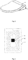
Fig. 1 shows a schematic structural diagram of an embodiment of the invention; -
Fig. 2 shows a schematic structural diagram of the embodiment of the invention; -
Fig. 3 shows a schematic structural diagram of an NFC electronic tag of the invention; -
Fig. 4 shows a partial enlarged drawing of the embodiment of the invention; and -
Fig. 5 shows a structural enlarged drawing of the embodiment of the invention. - The description on signs of the drawings: 10-top mount outer cover; 11-top mount seat ring; 12-top mount upper cover; 20-first supporting point; 201-plane part;
202-arc part; 30-first hinge part; 4-NFC electronic tag; 41-storage chip; 42-NFC coil; 43-bonding layer; 5-second supporting point; 6-second hinge part. - A preferred embodiment of the invention is introduced below with reference to the drawings of the description to make its technical contents clearer and convenient to understand.
- As shown in
Fig. 1 to Fig. 3 , the invention discloses an NFC smart top mount, including a top mountouter cover 10, a top mountupper cover 12 and a topmount seat ring 11, the topmount seat ring 11 is connected with the top mountouter cover 10 in a pivotable manner, the top mountupper cover 12 is connected with the top mountouter cover 10 through a first supportingpoint 20 and a second supporting point 5 in a pivotable manner, and pivoting angles and pivoting directions of the topmount seat ring 11 and the top mountupper cover 12 are the same;
wherein, an NFCelectronic tag 4 is attached to an inner edge of the top mountouter cover 10 and includes anNFC coil 42 and astorage chip 41 electrically connected with the two ends of the NFC coil, and theNFC coil 42 is spirally distributed; and the NFCelectronic tag 4 feeds pre-stored data back to an NFC identification terminal in response to the approaching NFC identification terminal. - The
storage chip 41 of the NFCelectronic tag 4 can store related information of a current product, for example, a functional specification, after-sales channel information and the like, and through the NFC identification terminal, usually, after a mobile phone approaches the NFCelectronic tag 4, a user can receive a usage instructions of related functions. Besides, the NFCelectronic tag 4 further includes abonding layer 43, which is used for attaching the NFCelectronic tag 4 to the top mountouter cover 10, and the NFCelectronic tag 4 can be attached to any position of the top mountouter cover 10, usually on a position convenient for the user to contact, for example, a button edge of the smart top mount, etc. - The NFC
electronic tag 4 can be attached to the inside or outside of the top mountouter cover 10, as long as it ensures the identification terminal can identify the electronic tag. - Further, as shown in
Fig. 4 and Fig. 5 , the first supportingpoint 20 includes two oppositely-arrangedplane parts 201 and two oppositely-arrangedarc parts 202, theplane parts 201 and thearc parts 202 are mutually connected, the first supportingpoint 20 is fixedly connected with the top mountouter cover 10, the top mountupper cover 12 includes afirst hinge part 30 and asecond hinge part 6 respectively connected with the first supportingpoint 20 and the second supporting point 5, the first hinge part includes a cavity and an opening, the first supportingpoint 20 enters the cavity along the opening, and a center of the cavity is superposed with an axis of the first supportingpoint 20. - The first supporting
point 20 is composed of the two oppositely-arrangedplane parts 201 and the two oppositely-arrangedarc parts 202, forming an oblateness-like shape, is fixed to the top mountouter cover 10, and thus cannot rotate. Thefirst hinge part 30 is of a U'-like structure, and the first supportingpoint 20 enters the cavity of thefirst hinge part 30 from its opening, thereby enabling the top mountupper cover 12 to pivot along the first supportingpoint 20. For thesecond hinge part 6, it should be connected with the turnover second supporting point 5, thereby achieving overall pivoting function of the top mountupper cover 12. - Further, radians of the
arc parts 202 are the same as a radian in the cavity, thereby enabling the top mountupper cover 12 to overturn more smoothly. - Further, a width of the opening is smaller than a relative distance between the two
plane parts 201. The smart top mount is usually made of plastic and thus has certain elasticity, in the case that the width of the opening is smaller than the relative distance between the twoplane parts 201, the opening is propped open by the first supportingpoint 20 firstly, and after reaching a mounting position, the opening is closed to enclose the first supportingpoint 20, thereby avoiding the top mountupper cover 12 from being accidentally separated from the first supportingpoint 20 during using and enhancing the stability in use. - Further, the second supporting point 5 is a damper, and the
second hinge part 6 is in an interference fit with the damper. Thus a slow-descending function can be added to the smart top mount, so that using is safer. - Thus the top mount
upper cover 12 can be conveniently detached from the smart top mount according to needs. As long as an opening surface is adjusted to be perpendicular to extension directions of theplane parts 201, thefirst hinge part 30 can be separated from the first supportingpoint 20 by upwards lifting the top mountupper cover 12 at the moment, and then thesecond hinge part 6 is transversely detached from the second supporting point 5.
Claims (5)
- An NFC smart top mount, characterized in that the NFC smart top mount comprises a top mount outer cover, a top mount upper cover and a top mount seat ring, the top mount seat ring is connected with the top mount outer cover in a pivotable manner, the top mount upper cover is connected with the top mount outer cover through a first supporting point and a second supporting point in a pivotable manner, and pivoting angles and pivoting directions of the top mount seat ring and the top mount upper cover are the same;
wherein, an NFC electronic tag is attached to an inner edge of the top mount outer cover and comprises an NFC coil and a storage chip electrically connected with the NFC coil, and the NFC coil is spirally distributed; and the NFC electronic tag responds to an approaching NFC identification terminal and feeds pre-stored data back to the NFC identification terminal. - The NFC smart top mount according to claim 1, characterized in that the first supporting point comprises two oppositely-arranged plane parts and two oppositely-arranged arc parts, the plane parts and the arc parts are mutually connected, the first supporting point is fixedly connected with the top mount outer cover, the top mount upper cover comprises a first hinge part and a second hinge part respectively connected with the first supporting point and the second supporting point, the first hinge part comprises a cavity and an opening, the first supporting point enters the cavity along the opening, and a center of the cavity is superposed with an axis of the first supporting point.
- The NFC smart top mount according to claim 2, characterized in that bending radians of arc parts are consistent with a bending radian of a cavity.
- The NFC smart top mount according to claim 2 or 3, characterized in that the second supporting point is a damper, and a second hinge part is in an interference fit with the damper.
- The NFC smart top mount according to claim 2, 3 or 4, characterized in that a width of an opening is smaller than a relative distance between two plane parts.
Applications Claiming Priority (1)
| Application Number | Priority Date | Filing Date | Title |
|---|---|---|---|
| CN202022412572.4U CN214549215U (en) | 2020-10-27 | 2020-10-27 | NFC intelligence apron |
Publications (2)
| Publication Number | Publication Date |
|---|---|
| EP3991621A1 true EP3991621A1 (en) | 2022-05-04 |
| EP3991621B1 EP3991621B1 (en) | 2024-07-17 |
Family
ID=78347968
Family Applications (1)
| Application Number | Title | Priority Date | Filing Date |
|---|---|---|---|
| EP21204763.3A Active EP3991621B1 (en) | 2020-10-27 | 2021-10-26 | Nfc smart toilet top mount |
Country Status (2)
| Country | Link |
|---|---|
| EP (1) | EP3991621B1 (en) |
| CN (1) | CN214549215U (en) |
Citations (4)
| Publication number | Priority date | Publication date | Assignee | Title |
|---|---|---|---|---|
| CN203302977U (en) * | 2013-05-02 | 2013-11-27 | 周裕佳 | Toilet paper changing cover with anti-counterfeiting identification system |
| US20180213984A1 (en) * | 2017-02-01 | 2018-08-02 | Toto Ltd. | Toilet apparatus |
| EP3357387A1 (en) * | 2017-02-07 | 2018-08-08 | Geberit International AG | Toilet seat ring assembly |
| JP2020151021A (en) * | 2019-03-18 | 2020-09-24 | Simplex Quantum株式会社 | Electrocardiographic measuring device |
-
2020
- 2020-10-27 CN CN202022412572.4U patent/CN214549215U/en active Active
-
2021
- 2021-10-26 EP EP21204763.3A patent/EP3991621B1/en active Active
Patent Citations (4)
| Publication number | Priority date | Publication date | Assignee | Title |
|---|---|---|---|---|
| CN203302977U (en) * | 2013-05-02 | 2013-11-27 | 周裕佳 | Toilet paper changing cover with anti-counterfeiting identification system |
| US20180213984A1 (en) * | 2017-02-01 | 2018-08-02 | Toto Ltd. | Toilet apparatus |
| EP3357387A1 (en) * | 2017-02-07 | 2018-08-08 | Geberit International AG | Toilet seat ring assembly |
| JP2020151021A (en) * | 2019-03-18 | 2020-09-24 | Simplex Quantum株式会社 | Electrocardiographic measuring device |
Also Published As
| Publication number | Publication date |
|---|---|
| EP3991621B1 (en) | 2024-07-17 |
| CN214549215U (en) | 2021-11-02 |
Similar Documents
| Publication | Publication Date | Title |
|---|---|---|
| US6895261B1 (en) | Portable, wireless communication apparatus integrated with garment | |
| US20040052389A1 (en) | Microphone/earpiece device for a mobile telephone, telephone, exchange or the like | |
| US20030144039A1 (en) | Communication cord pathway concealed clothes | |
| US20090111535A1 (en) | Headset | |
| EP3991621A1 (en) | Nfc smart toilet top mount | |
| CN107071152A (en) | Method and system for automatically adjusting volume of sound equipment based on state of call equipment | |
| CN208439171U (en) | Sub-dashboard armrests of vehicles and vehicles | |
| WO2006037814A2 (en) | Personal communications device | |
| CN109619930A (en) | A kind of Intelligent bathroom mirror and its control system | |
| CN207427283U (en) | A kind of system that mobile portable phone is taken using expansion equipment | |
| JPH0964950A (en) | Mobile phone | |
| CN209046689U (en) | A kind of campaign-styled necklace mobile phone of old man | |
| CN108391328A (en) | The 5G for having 5G wireless broadband router functions fixes verbal system | |
| CN210276757U (en) | Dustproof multifunctional cup cover | |
| CN203851262U (en) | Intelligent watch equipped with deployable type folding microphone | |
| CN208015940U (en) | A kind of choker bluetooth headset | |
| CN216356851U (en) | Cell-phone protective sheath convenient to cell-phone of taking | |
| CN214341516U (en) | Intelligent cup cover | |
| CN212572532U (en) | Interphone with Bluetooth function | |
| CN201094312Y (en) | Wireless signal receiving inducted lamp cap | |
| KR200226309Y1 (en) | Folder type cellular phone cover with mirror | |
| KR20000024290A (en) | Cellular phone with built-in a hands free kit being extractable | |
| KR200244997Y1 (en) | Hands-Free Device For Mobile Station | |
| JP3078668U (en) | Hanging earphone microphone set for mobile phones | |
| CN208441189U (en) | A kind of closestool with voice play function |
Legal Events
| Date | Code | Title | Description |
|---|---|---|---|
| PUAI | Public reference made under article 153(3) epc to a published international application that has entered the european phase |
Free format text: ORIGINAL CODE: 0009012 |
|
| STAA | Information on the status of an ep patent application or granted ep patent |
Free format text: STATUS: THE APPLICATION HAS BEEN PUBLISHED |
|
| STAA | Information on the status of an ep patent application or granted ep patent |
Free format text: STATUS: REQUEST FOR EXAMINATION WAS MADE |
|
| AK | Designated contracting states |
Kind code of ref document: A1 Designated state(s): AL AT BE BG CH CY CZ DE DK EE ES FI FR GB GR HR HU IE IS IT LI LT LU LV MC MK MT NL NO PL PT RO RS SE SI SK SM TR |
|
| 17P | Request for examination filed |
Effective date: 20220427 |
|
| RBV | Designated contracting states (corrected) |
Designated state(s): AL AT BE BG CH CY CZ DE DK EE ES FI FR GB GR HR HU IE IS IT LI LT LU LV MC MK MT NL NO PL PT RO RS SE SI SK SM TR |
|
| GRAP | Despatch of communication of intention to grant a patent |
Free format text: ORIGINAL CODE: EPIDOSNIGR1 |
|
| STAA | Information on the status of an ep patent application or granted ep patent |
Free format text: STATUS: GRANT OF PATENT IS INTENDED |
|
| INTG | Intention to grant announced |
Effective date: 20240412 |
|
| GRAS | Grant fee paid |
Free format text: ORIGINAL CODE: EPIDOSNIGR3 |
|
| GRAA | (expected) grant |
Free format text: ORIGINAL CODE: 0009210 |
|
| STAA | Information on the status of an ep patent application or granted ep patent |
Free format text: STATUS: THE PATENT HAS BEEN GRANTED |
|
| AK | Designated contracting states |
Kind code of ref document: B1 Designated state(s): AL AT BE BG CH CY CZ DE DK EE ES FI FR GB GR HR HU IE IS IT LI LT LU LV MC MK MT NL NO PL PT RO RS SE SI SK SM TR |
|
| REG | Reference to a national code |
Ref country code: CH Ref legal event code: EP |
|
| REG | Reference to a national code |
Ref country code: DE Ref legal event code: R096 Ref document number: 602021015749 Country of ref document: DE |
|
| P01 | Opt-out of the competence of the unified patent court (upc) registered |
Free format text: CASE NUMBER: APP_40386/2024 Effective date: 20240708 |
|
| REG | Reference to a national code |
Ref country code: IE Ref legal event code: FG4D |
|
| REG | Reference to a national code |
Ref country code: NL Ref legal event code: FP |
|
| REG | Reference to a national code |
Ref country code: LT Ref legal event code: MG9D |
|
| PG25 | Lapsed in a contracting state [announced via postgrant information from national office to epo] |
Ref country code: PT Free format text: LAPSE BECAUSE OF FAILURE TO SUBMIT A TRANSLATION OF THE DESCRIPTION OR TO PAY THE FEE WITHIN THE PRESCRIBED TIME-LIMIT Effective date: 20241118 |
|
| REG | Reference to a national code |
Ref country code: AT Ref legal event code: UEP Ref document number: 1703312 Country of ref document: AT Kind code of ref document: T Effective date: 20240717 |
|
| PG25 | Lapsed in a contracting state [announced via postgrant information from national office to epo] |
Ref country code: PT Free format text: LAPSE BECAUSE OF FAILURE TO SUBMIT A TRANSLATION OF THE DESCRIPTION OR TO PAY THE FEE WITHIN THE PRESCRIBED TIME-LIMIT Effective date: 20241118 |
|
| PG25 | Lapsed in a contracting state [announced via postgrant information from national office to epo] |
Ref country code: NO Free format text: LAPSE BECAUSE OF FAILURE TO SUBMIT A TRANSLATION OF THE DESCRIPTION OR TO PAY THE FEE WITHIN THE PRESCRIBED TIME-LIMIT Effective date: 20241017 |
|
| PG25 | Lapsed in a contracting state [announced via postgrant information from national office to epo] |
Ref country code: FI Free format text: LAPSE BECAUSE OF FAILURE TO SUBMIT A TRANSLATION OF THE DESCRIPTION OR TO PAY THE FEE WITHIN THE PRESCRIBED TIME-LIMIT Effective date: 20240717 Ref country code: GR Free format text: LAPSE BECAUSE OF FAILURE TO SUBMIT A TRANSLATION OF THE DESCRIPTION OR TO PAY THE FEE WITHIN THE PRESCRIBED TIME-LIMIT Effective date: 20241018 Ref country code: PL Free format text: LAPSE BECAUSE OF FAILURE TO SUBMIT A TRANSLATION OF THE DESCRIPTION OR TO PAY THE FEE WITHIN THE PRESCRIBED TIME-LIMIT Effective date: 20240717 |
|
| PG25 | Lapsed in a contracting state [announced via postgrant information from national office to epo] |
Ref country code: BG Free format text: LAPSE BECAUSE OF FAILURE TO SUBMIT A TRANSLATION OF THE DESCRIPTION OR TO PAY THE FEE WITHIN THE PRESCRIBED TIME-LIMIT Effective date: 20240717 |
|
| PG25 | Lapsed in a contracting state [announced via postgrant information from national office to epo] |
Ref country code: LV Free format text: LAPSE BECAUSE OF FAILURE TO SUBMIT A TRANSLATION OF THE DESCRIPTION OR TO PAY THE FEE WITHIN THE PRESCRIBED TIME-LIMIT Effective date: 20240717 |
|
| PG25 | Lapsed in a contracting state [announced via postgrant information from national office to epo] |
Ref country code: IS Free format text: LAPSE BECAUSE OF FAILURE TO SUBMIT A TRANSLATION OF THE DESCRIPTION OR TO PAY THE FEE WITHIN THE PRESCRIBED TIME-LIMIT Effective date: 20241117 |
|
| PG25 | Lapsed in a contracting state [announced via postgrant information from national office to epo] |
Ref country code: HR Free format text: LAPSE BECAUSE OF FAILURE TO SUBMIT A TRANSLATION OF THE DESCRIPTION OR TO PAY THE FEE WITHIN THE PRESCRIBED TIME-LIMIT Effective date: 20240717 |
|
| PG25 | Lapsed in a contracting state [announced via postgrant information from national office to epo] |
Ref country code: ES Free format text: LAPSE BECAUSE OF FAILURE TO SUBMIT A TRANSLATION OF THE DESCRIPTION OR TO PAY THE FEE WITHIN THE PRESCRIBED TIME-LIMIT Effective date: 20240717 Ref country code: RS Free format text: LAPSE BECAUSE OF FAILURE TO SUBMIT A TRANSLATION OF THE DESCRIPTION OR TO PAY THE FEE WITHIN THE PRESCRIBED TIME-LIMIT Effective date: 20241017 |
|
| PG25 | Lapsed in a contracting state [announced via postgrant information from national office to epo] |
Ref country code: RS Free format text: LAPSE BECAUSE OF FAILURE TO SUBMIT A TRANSLATION OF THE DESCRIPTION OR TO PAY THE FEE WITHIN THE PRESCRIBED TIME-LIMIT Effective date: 20241017 Ref country code: PL Free format text: LAPSE BECAUSE OF FAILURE TO SUBMIT A TRANSLATION OF THE DESCRIPTION OR TO PAY THE FEE WITHIN THE PRESCRIBED TIME-LIMIT Effective date: 20240717 Ref country code: NO Free format text: LAPSE BECAUSE OF FAILURE TO SUBMIT A TRANSLATION OF THE DESCRIPTION OR TO PAY THE FEE WITHIN THE PRESCRIBED TIME-LIMIT Effective date: 20241017 Ref country code: LV Free format text: LAPSE BECAUSE OF FAILURE TO SUBMIT A TRANSLATION OF THE DESCRIPTION OR TO PAY THE FEE WITHIN THE PRESCRIBED TIME-LIMIT Effective date: 20240717 Ref country code: IS Free format text: LAPSE BECAUSE OF FAILURE TO SUBMIT A TRANSLATION OF THE DESCRIPTION OR TO PAY THE FEE WITHIN THE PRESCRIBED TIME-LIMIT Effective date: 20241117 Ref country code: HR Free format text: LAPSE BECAUSE OF FAILURE TO SUBMIT A TRANSLATION OF THE DESCRIPTION OR TO PAY THE FEE WITHIN THE PRESCRIBED TIME-LIMIT Effective date: 20240717 Ref country code: GR Free format text: LAPSE BECAUSE OF FAILURE TO SUBMIT A TRANSLATION OF THE DESCRIPTION OR TO PAY THE FEE WITHIN THE PRESCRIBED TIME-LIMIT Effective date: 20241018 Ref country code: FI Free format text: LAPSE BECAUSE OF FAILURE TO SUBMIT A TRANSLATION OF THE DESCRIPTION OR TO PAY THE FEE WITHIN THE PRESCRIBED TIME-LIMIT Effective date: 20240717 Ref country code: ES Free format text: LAPSE BECAUSE OF FAILURE TO SUBMIT A TRANSLATION OF THE DESCRIPTION OR TO PAY THE FEE WITHIN THE PRESCRIBED TIME-LIMIT Effective date: 20240717 Ref country code: BG Free format text: LAPSE BECAUSE OF FAILURE TO SUBMIT A TRANSLATION OF THE DESCRIPTION OR TO PAY THE FEE WITHIN THE PRESCRIBED TIME-LIMIT Effective date: 20240717 |
|
| REG | Reference to a national code |
Ref country code: DE Ref legal event code: R082 Ref document number: 602021015749 Country of ref document: DE Representative=s name: SZYNKA SMORODIN PATENTANWAELTE PARTNERSCHAFT M, DE |
|
| PG25 | Lapsed in a contracting state [announced via postgrant information from national office to epo] |
Ref country code: DK Free format text: LAPSE BECAUSE OF FAILURE TO SUBMIT A TRANSLATION OF THE DESCRIPTION OR TO PAY THE FEE WITHIN THE PRESCRIBED TIME-LIMIT Effective date: 20240717 Ref country code: RO Free format text: LAPSE BECAUSE OF FAILURE TO SUBMIT A TRANSLATION OF THE DESCRIPTION OR TO PAY THE FEE WITHIN THE PRESCRIBED TIME-LIMIT Effective date: 20240717 Ref country code: SM Free format text: LAPSE BECAUSE OF FAILURE TO SUBMIT A TRANSLATION OF THE DESCRIPTION OR TO PAY THE FEE WITHIN THE PRESCRIBED TIME-LIMIT Effective date: 20240717 |
|
| REG | Reference to a national code |
Ref country code: DE Ref legal event code: R097 Ref document number: 602021015749 Country of ref document: DE |
|
| PG25 | Lapsed in a contracting state [announced via postgrant information from national office to epo] |
Ref country code: EE Free format text: LAPSE BECAUSE OF FAILURE TO SUBMIT A TRANSLATION OF THE DESCRIPTION OR TO PAY THE FEE WITHIN THE PRESCRIBED TIME-LIMIT Effective date: 20240717 |
|
| PG25 | Lapsed in a contracting state [announced via postgrant information from national office to epo] |
Ref country code: CZ Free format text: LAPSE BECAUSE OF FAILURE TO SUBMIT A TRANSLATION OF THE DESCRIPTION OR TO PAY THE FEE WITHIN THE PRESCRIBED TIME-LIMIT Effective date: 20240717 |
|
| PG25 | Lapsed in a contracting state [announced via postgrant information from national office to epo] |
Ref country code: SK Free format text: LAPSE BECAUSE OF FAILURE TO SUBMIT A TRANSLATION OF THE DESCRIPTION OR TO PAY THE FEE WITHIN THE PRESCRIBED TIME-LIMIT Effective date: 20240717 |
|
| PLBE | No opposition filed within time limit |
Free format text: ORIGINAL CODE: 0009261 |
|
| STAA | Information on the status of an ep patent application or granted ep patent |
Free format text: STATUS: NO OPPOSITION FILED WITHIN TIME LIMIT |
|
| 26N | No opposition filed |
Effective date: 20250422 |
|
| PG25 | Lapsed in a contracting state [announced via postgrant information from national office to epo] |
Ref country code: MC Free format text: LAPSE BECAUSE OF FAILURE TO SUBMIT A TRANSLATION OF THE DESCRIPTION OR TO PAY THE FEE WITHIN THE PRESCRIBED TIME-LIMIT Effective date: 20240717 |
|
| PG25 | Lapsed in a contracting state [announced via postgrant information from national office to epo] |
Ref country code: LU Free format text: LAPSE BECAUSE OF NON-PAYMENT OF DUE FEES Effective date: 20241026 Ref country code: BE Free format text: LAPSE BECAUSE OF NON-PAYMENT OF DUE FEES Effective date: 20241031 |
|
| REG | Reference to a national code |
Ref country code: BE Ref legal event code: MM Effective date: 20241031 |
|
| PG25 | Lapsed in a contracting state [announced via postgrant information from national office to epo] |
Ref country code: SE Free format text: LAPSE BECAUSE OF FAILURE TO SUBMIT A TRANSLATION OF THE DESCRIPTION OR TO PAY THE FEE WITHIN THE PRESCRIBED TIME-LIMIT Effective date: 20240717 |
|
| PG25 | Lapsed in a contracting state [announced via postgrant information from national office to epo] |
Ref country code: IE Free format text: LAPSE BECAUSE OF NON-PAYMENT OF DUE FEES Effective date: 20241026 |
|
| REG | Reference to a national code |
Ref country code: CH Ref legal event code: U11 Free format text: ST27 STATUS EVENT CODE: U-0-0-U10-U11 (AS PROVIDED BY THE NATIONAL OFFICE) Effective date: 20251101 |
|
| PGFP | Annual fee paid to national office [announced via postgrant information from national office to epo] |
Ref country code: NL Payment date: 20251023 Year of fee payment: 5 |
|
| PGFP | Annual fee paid to national office [announced via postgrant information from national office to epo] |
Ref country code: DE Payment date: 20251020 Year of fee payment: 5 |
|
| PGFP | Annual fee paid to national office [announced via postgrant information from national office to epo] |
Ref country code: GB Payment date: 20251024 Year of fee payment: 5 |
|
| PGFP | Annual fee paid to national office [announced via postgrant information from national office to epo] |
Ref country code: AT Payment date: 20260113 Year of fee payment: 5 |
|
| PGFP | Annual fee paid to national office [announced via postgrant information from national office to epo] |
Ref country code: IT Payment date: 20251031 Year of fee payment: 5 |
|
| PG25 | Lapsed in a contracting state [announced via postgrant information from national office to epo] |
Ref country code: IT Free format text: LAPSE BECAUSE OF NON-PAYMENT OF DUE FEES Effective date: 20241026 |
|
| PGFP | Annual fee paid to national office [announced via postgrant information from national office to epo] |
Ref country code: FR Payment date: 20251024 Year of fee payment: 5 |
|
| PGFP | Annual fee paid to national office [announced via postgrant information from national office to epo] |
Ref country code: CH Payment date: 20251101 Year of fee payment: 5 |
|
| PG25 | Lapsed in a contracting state [announced via postgrant information from national office to epo] |
Ref country code: CY Free format text: LAPSE BECAUSE OF FAILURE TO SUBMIT A TRANSLATION OF THE DESCRIPTION OR TO PAY THE FEE WITHIN THE PRESCRIBED TIME-LIMIT; INVALID AB INITIO Effective date: 20211026 |
|
| PG25 | Lapsed in a contracting state [announced via postgrant information from national office to epo] |
Ref country code: HU Free format text: LAPSE BECAUSE OF FAILURE TO SUBMIT A TRANSLATION OF THE DESCRIPTION OR TO PAY THE FEE WITHIN THE PRESCRIBED TIME-LIMIT; INVALID AB INITIO Effective date: 20211026 |
|
| PG25 | Lapsed in a contracting state [announced via postgrant information from national office to epo] |
Ref country code: IT Free format text: LAPSE BECAUSE OF NON-PAYMENT OF DUE FEES Effective date: 20241026 |
|
| PGRI | Patent reinstated in contracting state [announced from national office to epo] |
Ref country code: IT Effective date: 20241031 |