EP3991619A1 - Toilet top mount drying device - Google Patents
Toilet top mount drying device Download PDFInfo
- Publication number
- EP3991619A1 EP3991619A1 EP21204790.6A EP21204790A EP3991619A1 EP 3991619 A1 EP3991619 A1 EP 3991619A1 EP 21204790 A EP21204790 A EP 21204790A EP 3991619 A1 EP3991619 A1 EP 3991619A1
- Authority
- EP
- European Patent Office
- Prior art keywords
- air
- segment
- sectional area
- drying device
- air segment
- Prior art date
- Legal status (The legal status is an assumption and is not a legal conclusion. Google has not performed a legal analysis and makes no representation as to the accuracy of the status listed.)
- Withdrawn
Links
Images

Classifications
-
- A—HUMAN NECESSITIES
- A47—FURNITURE; DOMESTIC ARTICLES OR APPLIANCES; COFFEE MILLS; SPICE MILLS; SUCTION CLEANERS IN GENERAL
- A47K—SANITARY EQUIPMENT; ACCESSORIES THEREFOR, e.g. TOILET ACCESSORIES
- A47K13/00—Seats or covers for all kinds of closets
- A47K13/24—Parts or details not covered in, or of interest apart from, groups A47K13/02 - A47K13/22
- A47K13/30—Seats having provisions for heating, deodorising or the like, e.g. ventilating, noise-damping or cleaning devices
- A47K13/305—Seats with heating devices
-
- A—HUMAN NECESSITIES
- A47—FURNITURE; DOMESTIC ARTICLES OR APPLIANCES; COFFEE MILLS; SPICE MILLS; SUCTION CLEANERS IN GENERAL
- A47K—SANITARY EQUIPMENT; ACCESSORIES THEREFOR, e.g. TOILET ACCESSORIES
- A47K10/00—Body-drying implements; Toilet paper; Holders therefor
- A47K10/48—Drying by means of hot air
-
- E—FIXED CONSTRUCTIONS
- E03—WATER SUPPLY; SEWERAGE
- E03D—WATER-CLOSETS OR URINALS WITH FLUSHING DEVICES; FLUSHING VALVES THEREFOR
- E03D9/00—Sanitary or other accessories for lavatories ; Devices for cleaning or disinfecting the toilet room or the toilet bowl; Devices for eliminating smells
- E03D9/04—Special arrangement or operation of ventilating devices
- E03D9/05—Special arrangement or operation of ventilating devices ventilating the bowl
- E03D9/052—Special arrangement or operation of ventilating devices ventilating the bowl using incorporated fans
Definitions
- the invention relates to the field of smart top mounts for toilets, in particular to a top mount drying device.
- the technical problem to be solved by the invention is to provide a top mount drying device with large air volume and without increasing the power consumption of a top mount at the same time.
- the invention provides a top mount drying device, including a fan, a heating unit, an air duct and an air outlet; the heating unit is located between the fan and the air duct, the air duct includes a first air segment, a second air segment and a third air segment that are sequentially ordered in an air-out direction, a sectional area of the second air segment is smaller than a sectional area of the first air segment, the sectional area of the first air segment is continuously decreased towards the sectional area of the second air segment, and a sectional area of the third air segment is the same as the sectional area of the second air segment, and the third air segment is connected with the air outlet.
- the third air segment is arranged to extend towards a center of a top mount seat ring.
- the air outlet is provided with an air guide grating, and the air guide grating divides the air duct into a plurality of air-out channels.
- a tail end of the second air segment is bent towards a water surface of a toilet by 10 degrees to 20 degrees.
- an included angle between transitional ends of the second air segment and the third air segment is 120 degrees to140 degrees.
- the air guide grating is arranged to face the center of the top mount seat ring, and an included angle between an extending line of the air guide grating towards the top mount seat ring and the air outlet is 100 degrees to 120 degrees.
- the heating unit is an electric heating wire.
- the invention has the technical effect that the air-out speed is further increased on the basis of the same power consumption, thereby improving usage experience of users.
- the invention provides a top mount drying device 1, including a fan 10, a heating unit 11, an air duct 12 and an air outlet 13; the heating unit 11 is located between the fan 10 and the air duct 12, the air duct 12 includes a first air segment 121, a second air segment 122 and a third air segment 123 that are sequentially ordered in an air-out direction, a sectional area of the second air segment 122 is smaller than a sectional area of the first air segment 121, the sectional area of the first air segment 121 is continuously decreased towards the sectional area of the second air segment 122, a sectional area of the third air segment 123 is the same as the sectional area of the second air segment 122, and the third air segment 123 is connected with the air outlet 13.
- the fan 10, the heating unit 11 and the air duct 12 are all located in a housing of the top mount drying device 1 to make air produced by the fan 10 blown out only through the air duct 12 and from the air outlet 13. Since the sectional area of the second air segment 122 is smaller than the sectional area of the first air segment 121, the air speed passing through the second air segment 122 and the third air segment 123 will be further increased and the drying effect is enhanced due to the reduction of the sectional area after the air is blown out.
- a tail end of the second air segment 122 is bent towards a water surface of a toilet by 10 degrees to 20 degrees, preferably 19 degrees. Potential energy of the air in the second air segment 122 may be further increased, thereby increasing the air speed.
- the third air segment 123 is arranged to extend towards a center of a top mount seat ring 2.
- the third air segment 123 can guide the direction where the air is blown out, so that it blows out the sufficient amount of air towards buttocks of a user.
- an included angle between transitional ends of the second air segment 122 and the third air segment 123 is 120 degrees to 140 degrees, most preferably 132 degrees.
- the air outlet 13 is provided with an air guide grating 14, and the air guide grating 14 divides the air duct 12 into a plurality of air-out channels, which can further increase the air-out speed.
- the air guide grating 14 is arranged to face a center of the top mount seat ring 2, and an included angle between an extending line of the air guide grating 14 towards the top mount seat ring 2 and the air outlet 13 is 100 degrees to 120 degrees, most preferably, 108 degrees.
- the heating unit is an electric heating wire.
Landscapes
- Health & Medical Sciences (AREA)
- Public Health (AREA)
- Epidemiology (AREA)
- Life Sciences & Earth Sciences (AREA)
- Engineering & Computer Science (AREA)
- Hydrology & Water Resources (AREA)
- Water Supply & Treatment (AREA)
- Bidet-Like Cleaning Device And Other Flush Toilet Accessories (AREA)
Abstract
The invention discloses a top mount drying device, and relates to the field of smart top mounts for toilets. The top mount drying device includes a fan, a heating unit, an air duct and an air outlet; the heating unit is located between the fan and the air duct, the air duct includes a first air segment, a second air segment and a third air segment which are sequentially ordered in an air-out direction, a sectional area of the second air segment is smaller than a sectional area of the first air segment, the sectional area of the first air segment is continuously decreased towards the sectional area of the second air segment, a sectional area of the third air segment is the same as the sectional area of the second air segment, and the third air segment is connected with the air outlet. The invention has the technical effect that the air-out speed is further increased on the basis of the same power consumption, thereby improving usage experience of users.
Description
- The invention relates to the field of smart top mounts for toilets, in particular to a top mount drying device.
- With the improvement of people's living standards and hygiene awareness, the popularizing rate of smart toilets is getting higher and higher. Many families have already chosen smart toilets when renovating, and moreover, some families have replaced ordinary toilet covers with smart toilet top mounts. In addition, some hotels and guest houses are also equipped with the smart toilets, making the application of the smart toilets wider.
- With the increasement of user demands, a variety of functions have been simultaneously integrated into a single smart top mount for a toilet, such as heating, warm water cleaning, warm air drying, deodorization and sterilization, and other functions. However, as for a drying device for a current smart top mount, due to its unreasonable air duct design, air-out cannot reach the expectation, thereby leading to a poor drying effect.
- In view of the above defects of the prior art, the technical problem to be solved by the invention is to provide a top mount drying device with large air volume and without increasing the power consumption of a top mount at the same time.
- In order to achieve the above purposes, the invention provides a top mount drying device, including a fan, a heating unit, an air duct and an air outlet; the heating unit is located between the fan and the air duct, the air duct includes a first air segment, a second air segment and a third air segment that are sequentially ordered in an air-out direction, a sectional area of the second air segment is smaller than a sectional area of the first air segment, the sectional area of the first air segment is continuously decreased towards the sectional area of the second air segment, and a sectional area of the third air segment is the same as the sectional area of the second air segment, and the third air segment is connected with the air outlet.
- Further, the third air segment is arranged to extend towards a center of a top mount seat ring.
- Further, the air outlet is provided with an air guide grating, and the air guide grating divides the air duct into a plurality of air-out channels.
- Further, a tail end of the second air segment is bent towards a water surface of a toilet by 10 degrees to 20 degrees.
- Further, an included angle between transitional ends of the second air segment and the third air segment is 120 degrees to140 degrees.
- Further, the air guide grating is arranged to face the center of the top mount seat ring, and an included angle between an extending line of the air guide grating towards the top mount seat ring and the air outlet is 100 degrees to 120 degrees.
- Further, the heating unit is an electric heating wire.
- The invention has the technical effect that the air-out speed is further increased on the basis of the same power consumption, thereby improving usage experience of users.
- The conception, specific structure and produced technical effect of the invention will be further explained below in combination with the drawings to fully understand the purposes, features and effects of the invention.
- By reading the detailed description of the non-restrictive embodiment with reference to the drawings below, other features, purposes and advantages of the invention will be more apparent:
-
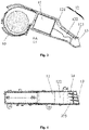
Fig. 1 shows a schematic structural diagram of an embodiment of the invention; -
Fig. 2 shows a structural top view of the embodiment of the invention; -
Fig. 3 shows a structural sectional view of the embodiment of the invention; and -
Fig. 4 shows a top view of parts of structures of the embodiment of the invention. - The description on signs of the drawings: 1-top mount drying device; 2-top mount seat ring; 10-fan; 11-heating unit; 12-air duct; 121-first air segment; 122-second air segment; 123-third air segment; 13-air outlet; 14-air guide grating.
- A preferred embodiment of the invention is introduced below with reference to the drawings of the description to make its technical contents clearer and convenient to understand.
- As shown in
Fig. 1 to Fig. 4 , the invention provides a top mount drying device 1, including afan 10, aheating unit 11, anair duct 12 and anair outlet 13; theheating unit 11 is located between thefan 10 and theair duct 12, theair duct 12 includes afirst air segment 121, asecond air segment 122 and athird air segment 123 that are sequentially ordered in an air-out direction, a sectional area of thesecond air segment 122 is smaller than a sectional area of thefirst air segment 121, the sectional area of thefirst air segment 121 is continuously decreased towards the sectional area of thesecond air segment 122, a sectional area of thethird air segment 123 is the same as the sectional area of thesecond air segment 122, and thethird air segment 123 is connected with theair outlet 13. - The
fan 10, theheating unit 11 and theair duct 12 are all located in a housing of the top mount drying device 1 to make air produced by thefan 10 blown out only through theair duct 12 and from theair outlet 13. Since the sectional area of thesecond air segment 122 is smaller than the sectional area of thefirst air segment 121, the air speed passing through thesecond air segment 122 and thethird air segment 123 will be further increased and the drying effect is enhanced due to the reduction of the sectional area after the air is blown out. Preferably, a tail end of thesecond air segment 122 is bent towards a water surface of a toilet by 10 degrees to 20 degrees, preferably 19 degrees. Potential energy of the air in thesecond air segment 122 may be further increased, thereby increasing the air speed. - Further, the
third air segment 123 is arranged to extend towards a center of a topmount seat ring 2. Thus, thethird air segment 123 can guide the direction where the air is blown out, so that it blows out the sufficient amount of air towards buttocks of a user. Preferably, an included angle between transitional ends of thesecond air segment 122 and thethird air segment 123 is 120 degrees to 140 degrees, most preferably 132 degrees. - Further, the
air outlet 13 is provided with an air guide grating 14, and the air guide grating 14 divides theair duct 12 into a plurality of air-out channels, which can further increase the air-out speed. - Preferably, the
air guide grating 14 is arranged to face a center of the topmount seat ring 2, and an included angle between an extending line of the air guide grating 14 towards the topmount seat ring 2 and theair outlet 13 is 100 degrees to 120 degrees, most preferably, 108 degrees. - Further, the heating unit is an electric heating wire.
Claims (8)
- A drying device for a toilet top mount, characterized in that the top mount drying device comprises a fan, a heating unit, an air duct and an air outlet; the heating unit is located between the fan and the air duct, the air duct comprises a first air segment, a second air segment and a third air segment that are sequentially ordered in an air-out direction, a sectional area of the second air segment is smaller than a sectional area of the first air segment, the sectional area of the first air segment is continuously decreased towards the sectional area of the second air segment, a sectional area of the third air segment is the same as the sectional area of the second air segment, and the third air segment is connected with the air outlet.
- The drying device according to claim 1, characterized in that the third air segment is arranged to extend towards a center of a top mount seat ring.
- The drying device according to claim 1 or 2, characterized in that the air outlet is provided with an air guide grating, and the air guide grating divides the air duct into a plurality of air-out channels.
- The drying device according to one of the preceding claims, characterized in that a tail end of the second air segment is bent towards a water surface of a toilet by 10 degrees to 20 degrees.
- The drying device according to claim 2, optionally in combination with claim 3 or 4, characterized in that an included angle between transitional ends of the second air segment and the third air segment is 120 degrees to 140 degrees.
- The drying device according to claim 3, optionally in combination with claim 4 or 5 characterized in that the air guide grating is arranged to face a center of a top mount seat ring, and an included angle between an extending line of the air guide grating towards the top mount seat ring and the air outlet is 100 degrees to 120 degrees.
- The drying device according to one of the preceding claims, characterized in that the heating unit is an electric heating wire.
- A toilet top mount including a drying device according to one of the preceding claims.
Applications Claiming Priority (1)
| Application Number | Priority Date | Filing Date | Title |
|---|---|---|---|
| CN202022412531.5U CN213821206U (en) | 2020-10-27 | 2020-10-27 | Apron drying device |
Publications (1)
| Publication Number | Publication Date |
|---|---|
| EP3991619A1 true EP3991619A1 (en) | 2022-05-04 |
Family
ID=77011413
Family Applications (1)
| Application Number | Title | Priority Date | Filing Date |
|---|---|---|---|
| EP21204790.6A Withdrawn EP3991619A1 (en) | 2020-10-27 | 2021-10-26 | Toilet top mount drying device |
Country Status (3)
| Country | Link |
|---|---|
| EP (1) | EP3991619A1 (en) |
| CN (1) | CN213821206U (en) |
| DE (1) | DE202021004026U1 (en) |
Families Citing this family (1)
| Publication number | Priority date | Publication date | Assignee | Title |
|---|---|---|---|---|
| CN114794948A (en) * | 2022-04-07 | 2022-07-29 | 东莞市旭恒电子有限公司 | Toilet seat |
Citations (2)
| Publication number | Priority date | Publication date | Assignee | Title |
|---|---|---|---|---|
| KR20090132189A (en) * | 2008-06-20 | 2009-12-30 | 웅진코웨이주식회사 | Toilet seat bidet |
| CN109700363A (en) * | 2019-01-31 | 2019-05-03 | 厦门瑞尔特卫浴科技股份有限公司 | A kind of bathroom drying unit and its control method |
-
2020
- 2020-10-27 CN CN202022412531.5U patent/CN213821206U/en active Active
-
2021
- 2021-10-26 EP EP21204790.6A patent/EP3991619A1/en not_active Withdrawn
- 2021-10-26 DE DE202021004026.9U patent/DE202021004026U1/en active Active
Patent Citations (2)
| Publication number | Priority date | Publication date | Assignee | Title |
|---|---|---|---|---|
| KR20090132189A (en) * | 2008-06-20 | 2009-12-30 | 웅진코웨이주식회사 | Toilet seat bidet |
| CN109700363A (en) * | 2019-01-31 | 2019-05-03 | 厦门瑞尔特卫浴科技股份有限公司 | A kind of bathroom drying unit and its control method |
Also Published As
| Publication number | Publication date |
|---|---|
| CN213821206U (en) | 2021-07-30 |
| DE202021004026U1 (en) | 2022-06-01 |
Similar Documents
| Publication | Publication Date | Title |
|---|---|---|
| CN106108753B (en) | A kind of foot's blow-dry device | |
| CN213821206U (en) | Apron drying device | |
| CN209032058U (en) | A kind of bathroom cabinet | |
| CN208355324U (en) | A kind of dry body machine for shower house | |
| CN2414748Y (en) | Convenient drying, warm bathing and sauna cover | |
| CN106859464A (en) | Water stain shower house with can quickly drying up | |
| CN105972695B (en) | A kind of hanging type air conditioner | |
| CN206342408U (en) | Hand dryer | |
| CN208892456U (en) | One kind being used for the clean cleaning brush device of environmental friendly indoor | |
| CN208365717U (en) | A kind of window air cleaning unit | |
| CN218879126U (en) | Handrail area degassing unit with stoving function | |
| CN2818597Y (en) | Automatic deodorization device of toilet | |
| CN209236945U (en) | A kind of air disinfection device | |
| CN206929908U (en) | The air condition electric fan of convenient installation | |
| CN201451903U (en) | A comb with dust-absorbing function | |
| CN206410271U (en) | A new type of humidifier | |
| CN206151338U (en) | Roll shower of giving a rubdown with a damp towel | |
| JPH05270772A (en) | Elevator car | |
| CN207805310U (en) | A kind of use in toilet air purifier | |
| CN215077934U (en) | Unimpeded air outlet assembly and faucet structure | |
| CN216167180U (en) | Dust box and cleaning robot | |
| JP2557875Y2 (en) | Odor suction duct for toilet | |
| CN215016522U (en) | an integrated faucet | |
| CN207030695U (en) | A kind of elevator air-exchanging structure | |
| CN105078148B (en) | Chopsticks basket |
Legal Events
| Date | Code | Title | Description |
|---|---|---|---|
| PUAI | Public reference made under article 153(3) epc to a published international application that has entered the european phase |
Free format text: ORIGINAL CODE: 0009012 |
|
| STAA | Information on the status of an ep patent application or granted ep patent |
Free format text: STATUS: THE APPLICATION HAS BEEN PUBLISHED |
|
| AK | Designated contracting states |
Kind code of ref document: A1 Designated state(s): AL AT BE BG CH CY CZ DE DK EE ES FI FR GB GR HR HU IE IS IT LI LT LU LV MC MK MT NL NO PL PT RO RS SE SI SK SM TR |
|
| STAA | Information on the status of an ep patent application or granted ep patent |
Free format text: STATUS: THE APPLICATION IS DEEMED TO BE WITHDRAWN |
|
| 18D | Application deemed to be withdrawn |
Effective date: 20221105 |