EP3991586A1 - Flavor inhalation system, mouthpiece, and cartridge - Google Patents
Flavor inhalation system, mouthpiece, and cartridge Download PDFInfo
- Publication number
- EP3991586A1 EP3991586A1 EP19935317.8A EP19935317A EP3991586A1 EP 3991586 A1 EP3991586 A1 EP 3991586A1 EP 19935317 A EP19935317 A EP 19935317A EP 3991586 A1 EP3991586 A1 EP 3991586A1
- Authority
- EP
- European Patent Office
- Prior art keywords
- cartridge
- mouthpiece
- engagement
- flavor
- opening
- Prior art date
- Legal status (The legal status is an assumption and is not a legal conclusion. Google has not performed a legal analysis and makes no representation as to the accuracy of the status listed.)
- Withdrawn
Links
- 239000000796 flavoring agent Substances 0.000 title claims abstract description 108
- 235000019634 flavors Nutrition 0.000 title claims abstract description 108
- 238000010438 heat treatment Methods 0.000 claims description 14
- 230000003068 static effect Effects 0.000 claims description 12
- 230000002093 peripheral effect Effects 0.000 description 84
- 238000005192 partition Methods 0.000 description 10
- 238000003780 insertion Methods 0.000 description 9
- 230000037431 insertion Effects 0.000 description 9
- 238000009423 ventilation Methods 0.000 description 8
- 239000000463 material Substances 0.000 description 5
- 241000208125 Nicotiana Species 0.000 description 4
- 235000002637 Nicotiana tabacum Nutrition 0.000 description 4
- 239000011810 insulating material Substances 0.000 description 4
- 230000006698 induction Effects 0.000 description 3
- 239000010935 stainless steel Substances 0.000 description 3
- 229910001220 stainless steel Inorganic materials 0.000 description 3
- 239000000758 substrate Substances 0.000 description 3
- 230000001276 controlling effect Effects 0.000 description 2
- 238000006073 displacement reaction Methods 0.000 description 2
- 239000000835 fiber Substances 0.000 description 2
- 239000008187 granular material Substances 0.000 description 2
- 230000001105 regulatory effect Effects 0.000 description 2
- 238000005507 spraying Methods 0.000 description 2
- URAYPUMNDPQOKB-UHFFFAOYSA-N triacetin Chemical compound CC(=O)OCC(OC(C)=O)COC(C)=O URAYPUMNDPQOKB-UHFFFAOYSA-N 0.000 description 2
- NOOLISFMXDJSKH-UTLUCORTSA-N (+)-Neomenthol Chemical compound CC(C)[C@@H]1CC[C@@H](C)C[C@@H]1O NOOLISFMXDJSKH-UTLUCORTSA-N 0.000 description 1
- 244000223760 Cinnamomum zeylanicum Species 0.000 description 1
- RYGMFSIKBFXOCR-UHFFFAOYSA-N Copper Chemical compound [Cu] RYGMFSIKBFXOCR-UHFFFAOYSA-N 0.000 description 1
- 229910000599 Cr alloy Inorganic materials 0.000 description 1
- NOOLISFMXDJSKH-UHFFFAOYSA-N DL-menthol Natural products CC(C)C1CCC(C)CC1O NOOLISFMXDJSKH-UHFFFAOYSA-N 0.000 description 1
- 244000178870 Lavandula angustifolia Species 0.000 description 1
- 235000010663 Lavandula angustifolia Nutrition 0.000 description 1
- HBBGRARXTFLTSG-UHFFFAOYSA-N Lithium ion Chemical compound [Li+] HBBGRARXTFLTSG-UHFFFAOYSA-N 0.000 description 1
- 229910000990 Ni alloy Inorganic materials 0.000 description 1
- 229910000629 Rh alloy Inorganic materials 0.000 description 1
- 244000290333 Vanilla fragrans Species 0.000 description 1
- 235000009499 Vanilla fragrans Nutrition 0.000 description 1
- 235000012036 Vanilla tahitensis Nutrition 0.000 description 1
- 229920002301 cellulose acetate Polymers 0.000 description 1
- 239000000788 chromium alloy Substances 0.000 description 1
- 235000017803 cinnamon Nutrition 0.000 description 1
- 229910052802 copper Inorganic materials 0.000 description 1
- 239000010949 copper Substances 0.000 description 1
- 230000003247 decreasing effect Effects 0.000 description 1
- 230000000694 effects Effects 0.000 description 1
- 238000010292 electrical insulation Methods 0.000 description 1
- 230000005674 electromagnetic induction Effects 0.000 description 1
- 235000013773 glyceryl triacetate Nutrition 0.000 description 1
- 239000001087 glyceryl triacetate Substances 0.000 description 1
- 239000001102 lavandula vera Substances 0.000 description 1
- 235000018219 lavender Nutrition 0.000 description 1
- 229910001416 lithium ion Inorganic materials 0.000 description 1
- 229940041616 menthol Drugs 0.000 description 1
- 239000007769 metal material Substances 0.000 description 1
- 239000004014 plasticizer Substances 0.000 description 1
- PXXKQOPKNFECSZ-UHFFFAOYSA-N platinum rhodium Chemical compound [Rh].[Pt] PXXKQOPKNFECSZ-UHFFFAOYSA-N 0.000 description 1
- 229920001721 polyimide Polymers 0.000 description 1
- 239000000126 substance Substances 0.000 description 1
- 235000019505 tobacco product Nutrition 0.000 description 1
- 229960002622 triacetin Drugs 0.000 description 1
Images





Classifications
-
- A—HUMAN NECESSITIES
- A24—TOBACCO; CIGARS; CIGARETTES; SIMULATED SMOKING DEVICES; SMOKERS' REQUISITES
- A24F—SMOKERS' REQUISITES; MATCH BOXES; SIMULATED SMOKING DEVICES
- A24F40/00—Electrically operated smoking devices; Component parts thereof; Manufacture thereof; Maintenance or testing thereof; Charging means specially adapted therefor
- A24F40/40—Constructional details, e.g. connection of cartridges and battery parts
-
- A—HUMAN NECESSITIES
- A24—TOBACCO; CIGARS; CIGARETTES; SIMULATED SMOKING DEVICES; SMOKERS' REQUISITES
- A24F—SMOKERS' REQUISITES; MATCH BOXES; SIMULATED SMOKING DEVICES
- A24F40/00—Electrically operated smoking devices; Component parts thereof; Manufacture thereof; Maintenance or testing thereof; Charging means specially adapted therefor
- A24F40/20—Devices using solid inhalable precursors
Definitions
- the engagement section (protrusion) is engaged in the second groove in the housing.
- the pull-out retainer needs to be rotated in the circumferential direction before the engagement section is moved along the first groove. This prevents accidental disengagement of the engagement section and the second groove.
- a static frictional force acting between the holding section and the cartridge is greater than a static frictional force acting between an inner wall of the storage space and the cartridge.
- a static frictional force acting between the holding section of the pull-out retainer and the cartridge is greater than a static frictional force acting between the inner wall of the storage space and the cartridge. Therefore, when the pull-out retainer is detached from the housing, the cartridge can be reliably pulled out together with the pull-out retainer.
- a plurality of grooved portions are equally spaced in a circumferential direction.
- a repulsive force generated when the outer periphery of the cartridge bends is uniformly distributed in the circumferential direction. This allows the holding section to hold the cartridge with uniform force throughout its circumference.
- the engagement section is configured as an engagement surface having a planar shape.
- the opening is provided with a contact surface formed along the axial direction and capable of being in contact with the engagement surface.
- the engagement section is in contact with the contact surface formed in the opening of the housing along the axial direction. This reduces displacement (or shaking) of the pull-out retainer in a direction intersecting the axial direction with respect to the opening of the housing, and facilitates attachment and detachment of the pull-out retainer along the axial direction.
- the housing biases the engagement section inward in the radial direction.
- the pull-out retainer is prevented from accidentally falling off the housing.
- the outer periphery of the pull-out retainer has the finger hold on which the user can place fingers. This allows the user to attach and detach the pull-out retainer with fingers placed on the finger hold, and improves attachability and detachability of the pull-out retainer.
- a cross-section orthogonal to the axial direction has a flattened shape.
- the engagement section of the pull-out retainer and the opening of the housing are brought out of engagement. This allows the cartridge including the filter portion held by the holding section of the pull-out retainer to be detached from the housing together with the pull-out retainer, eliminates the need for the user to individually detach the cartridge and the pull-out retainer, and facilitates replacement of the cartridge.
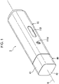
- an inhaler 1 which is an example of the flavor inhalation system according to the first embodiment, is a so-called heated tobacco product.
- the inhaler 1 heats tobacco leaves to produce vapor, and allows the user to inhale the vapor and enjoy flavor of the tobacco leaves.
- the outer shape of the inhaler 1 is a substantially rectangular columnar shape centered on the axis line O.
- the main unit 10, the cartridge 20, the mouthpiece 30, and the cap 40 are arranged on the axis line O.
- one side of the main unit 10 to which the mouthpiece 30 is disposed is referred to as an outlet side
- one side of the mouthpiece 30 to which the main unit 10 is disposed is referred to as a non-outlet side.
- a direction intersecting the axis line O is referred to as a radial direction.
- a radial direction toward the axis line O is referred to as an inward direction, and a radial direction away from the axis line O is referred to as an outward direction.
- a direction circling around the axis line O is referred to as a circumferential direction.
- direction refers to two directions, each of which is referred to as "side”.
- Fig. 3 is a cross-sectional view taken along line III-III in Fig. 2 .
- the main unit 10 includes a housing 11, a power supply unit 15, and a heater 16.
- the housing 11 includes a housing body 110, a mouthpiece supporting member 120, and a cartridge container 130.
- the housing body 110 includes an outer housing 111 and a bottom cap 116.
- the outer housing 111 is formed substantially in the shape of a rectangular cylinder centered on the axis line O.
- the outer housing 111 constitutes the outer surface of the inhaler 1.
- the outer housing 111 may be of any appropriate shape that will extend in the direction of the axis line O.
- a radial direction that connects the axis line O and the switch opening 111c is defined as a front-back direction.
- one side of the axis line O to which the switch opening 111c is disposed is defined as a front side
- the other side of the axis line O opposite the switch opening 111c is defined as a back side.
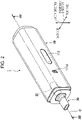
- the bottom cap 116 is disposed in the non-outlet side opening 111b of the outer housing 111.
- the bottom cap 116 is substantially rectangular in plan view, as viewed in the direction of the axis line O.
- the bottom cap 116 is configured to close the non-outlet side opening 111b of the outer housing 111.
- the bottom cap 116 may be of any appropriate shape that will close the non-outlet side opening 111b of the outer housing 111.
- the partition 118 has an outlet-side partition portion 118a and a lateral partition portion 118b. This reduces the flow of air heated by the heater 16 into the space for accommodating the battery 151. Accordingly, a rise in the temperature of the battery 151 is reduced.
- the outlet-side partition portion 118a is disposed to the outlet side of the battery 151.
- the lateral partition portion 118b is disposed to cover the exterior of the battery 151 in the circumferential direction.
- the mouthpiece supporting member 120 is disposed in the outlet-side opening 111a of the outer housing 111.
- Fig. 4 is a perspective view of the mouthpiece supporting member 120.
- the mouthpiece supporting member 120 includes a protruding cylinder 121, a fitting cylinder 126, and locking pieces 129.
- the protruding cylinder 121 includes an inner annular portion 122, an inner peripheral portion 123, and an engagement inner peripheral portion 124.
- the outer shape of the inner annular portion 122 is substantially rectangular in plan view, as viewed in the direction of the axis line O.
- the inner annular portion 122 may be of any appropriate shape, and is not limited to being substantially rectangular in plan view.
- the inner annular portion 122 has a mouthpiece opening (opening) 125 passing therethrough in the direction of the axis line O.
- the mouthpiece supporting member 120 has the mouthpiece opening 125 formed at an end portion thereof on the outlet side and passing therethrough in the direction of the axis line O.
- the mouthpiece opening 125 is substantially rectangular in plan view, as viewed in the direction of the axis line O. Note that the mouthpiece opening 125 may be of any appropriate shape, and is not limited to being substantially rectangular in plan view.
- Fig. 5 is an enlarged view of part A in Fig. 3 .
- the inner peripheral portion 123 extends from the outer edge of the inner annular portion 122 toward the non-outlet side.
- the inner peripheral portion 123 is disposed over the entire circumference of the inner annular portion 122 in the circumferential direction.
- the engagement inner peripheral portion 124 extends from the mouthpiece opening 125 in the inner annular portion 122 toward the non-outlet side.
- the engagement inner peripheral portion 124 is disposed over the entire circumference of the mouthpiece opening 125 in the circumferential direction.
- a direction orthogonal to the direction of the axis line O and the front-back direction is defined as a width direction.
- the engagement inner peripheral portion 124 is formed in a plate shape.
- a part 124a of the engagement inner peripheral portion 124 along the width direction is disposed with the plate thickness thereof being in the front-back direction.
- a part 124b of the engagement inner peripheral portion 124 along the front-back direction is disposed with the plate thickness thereof being in the width direction.
- An inner periphery (contact surface) 124i of the engagement inner peripheral portion 124 is formed in a planar shape along the direction of the axis line O.
- the slit 124s is formed to extend from an end portion of the engagement inner peripheral portion 124 on the non-outlet side toward the outlet side.
- the slit 124s penetrates the engagement inner peripheral portion 124 in the direction of the plate thickness thereof. This allows the engagement inner peripheral portion 124 to elastically deform in the direction of the plate thickness thereof.
- the fitting cylinder 126 includes an outer annular portion 127 and an outer peripheral portion 128.
- the outer annular portion 127 extends outward in the radial direction, from an end of the inner peripheral portion 123 of the protruding cylinder 121 on the non-outlet side.
- the outer annular portion 127 is disposed over the entire circumference of the inner peripheral portion 123 in the circumferential direction.
- the outer shape of the outer annular portion 127 is substantially rectangular in plan view, as viewed in the direction of the axis line O (see Fig. 4 ).
- the outer annular portion 127 may have any outer shape that will fit in the outlet-side opening 111a of the outer housing 111.
- a surface of the outer annular portion 127 on the outlet side is disposed to be flush with the end portion of the outer housing 111 on the outlet side.
- the protruding cylinder 121 is disposed to protrude toward the outlet side from the outlet-side opening 111a of the outer housing 111.
- the outer peripheral portion 128 extends from the outer edge of the outer annular portion 127 toward the non-outlet side.
- the outer peripheral portion 128 is disposed over the entire circumference of the outer annular portion 127 in the circumferential direction.
- the outer peripheral portion 128 is inserted through the outlet-side opening 111a of the outer housing 111 and fit to a portion of the outer housing 1 1 1 on the outlet side. In other words, the outer peripheral portion 128 is disposed in contact with the inner periphery of the outer housing 111 on the outlet side.
- a part 128b of the outer peripheral portion 128 along the front-back direction is provided with the locking piece 129 extending toward the non-outlet side.
- the locking piece 129 has a locking hole 129h passing therethrough in the width direction.
- the locking piece 129 has a locking protrusion 129c on the non-outlet side of the locking hole 129h.
- the locking protrusion 129c protrudes outward in the width direction (i.e., protrudes in a direction away from the axis line O).
- the locking protrusion 129c is locked in a recess (not shown) formed in the inner periphery of the outer housing 111 (see Fig. 5 ).
- the cartridge container 130 is disposed inside the inner cylindrical member 117, on the outlet side of the outlet-side partition portion 118a.
- the cartridge container 130 is formed by assembling a cylindrical container member 131 and a bottom member 136 together.
- the cylindrical container member 131 is disposed on the outlet side of the bottom member 136.
- the cylindrical container member 131 is formed in the shape of a circular cylinder centered on the axis line O.
- the cylindrical container member 131 may be of any appropriate shape that will extend in the direction of the axis line O.
- the cylindrical container member 131 has a cartridge supporting wall 132 formed at an end portion thereof on the outlet side and extending inward in the radial direction.
- the cartridge supporting wall 132 is annularly shaped in plan view, as viewed in the direction of the axis line O.
- the cartridge supporting wall 132 is preferably shaped to be capable of being in contact with the outer periphery of the cartridge 20 and may be of any appropriate shape.
- the bottom member 136 has a container recess 137a formed toward the non-outlet side.
- the container recess 137a is formed in a circular shape in plan view, as viewed in the direction of the axis line O.
- the outer housing 111 has a ventilation opening 111d formed on the front side thereof and passing therethrough in the front-back direction.
- the bottom member 136 has a bottom portion 137b at an end portion thereof on the non-outlet side, and an inflow-side opening 138a communicating with the ventilation opening 111d is formed on the front side of the bottom portion 137b.
- the bottom portion 137 has an outflow-side opening 138b formed at a bottom of the container recess 137a (i.e., formed in a surface orthogonal to the direction of the axis line O).
- a ventilation passage 138 is formed to allow the inflow-side opening 138a to communicate with the outflow-side opening 138b.
- the cartridge container 130 includes therein a cartridge supporting member 140.
- the cartridge supporting member 140 has a supporting bottom 141, a peripheral portion 142, and a flange 143.
- the cartridge supporting member 140 is formed of a material of high thermal conductivity, such as stainless steel.
- the supporting bottom 141 is disposed along the bottom of the container recess 137a in the cartridge container 130.
- the outer shape of the supporting bottom 141 is circular in plan view, as viewed in the direction of the axis line O.
- the supporting bottom 141 has a ventilation hole 141h passing therethrough in the direction of the axis line O.
- the ventilation hole 141h is formed in a circular shape centered on the axis line O in plan view, as viewed in the direction of the axis line O. Note that the supporting bottom 141 and the ventilation hole 141h may be of any appropriate shapes.
- An elastic O-ring 149a is disposed between the supporting bottom 141 of the cartridge supporting member 140 and the bottom of the container recess 137a.
- the peripheral portion 142 extends from the edge of the supporting bottom 141 toward the outlet side.
- the peripheral portion 142 is formed in the shape of a circular cylinder centered on the axis line O.
- the flange 143 extends outward in the radial direction, from an end of the peripheral portion 142 on the outlet side.
- the flange 143 is annularly shaped in plan view, as viewed in the direction of the axis line O.
- the flange 143 is disposed on the non-outlet side of the cartridge supporting wall 132 of the cartridge container 130.
- An elastic O-ring 149b is disposed between the flange 143 of the cartridge supporting member 140 and the cartridge supporting wall 132 of the cartridge container 130.
- the cartridge supporting member 140 has therein a cartridge storage space (storage space) s1 capable of storing the cartridge 20.
- the cartridge storage space s1 communicates with the mouthpiece opening 125 in the mouthpiece supporting member 120.
- the cartridge supporting member 140 is provided with a sensor (not shown), for example, at the supporting bottom 141.
- the sensor may be, for example, a temperature sensor or a gas component concentration sensor (chemical sensor).
- the temperature sensor is configured to measure or estimate the temperature of vapor containing a flavor component released from a flavor portion 23 (described below) of the cartridge 20.
- the gas component concentration sensor is configured to measure or estimate the concentration of vapor containing a flavor component released from the flavor portion 23 of the cartridge 20.
- the power supply unit 15 is formed by mounting, for example, the battery 151, a controller 152, and the heater 16 on the inner cylindrical member 117.
- the battery 151 inside the inner cylindrical member 117 is disposed on the non-outlet side of the outlet-side partition portion 118a.
- the battery 151 is formed in the shape of a circular column centered on an axis parallel to the axis line O.
- the battery 151 is a chargeable and dischargeable secondary battery.
- the battery 151 may be a lithium-ion battery.
- the battery 151 may be of any appropriate shape.
- the controller 152 inside the inner cylindrical member 117 is disposed on the front side of the lateral partition portion 118b.
- the controller 152 is disposed between the lateral partition portion 118b and the front side of the outer housing 111.
- the battery 151 and the heater 16 are electrically connected through the controller 152 by a wire (not shown).
- the controller 152 includes switch elements 152a at positions corresponding to the switch 112 disposed on the front side of the outer housing 111.
- the controller 152 controls the battery 151 and the heater 16 in accordance with the operation of the switch 112.
- the controller 152 is configured to control current flowing from the battery 151 to the heater 16. This makes it possible to control the heating temperature at which to heat the flavor portion 23 of the cartridge 20.
- the heater 16 is disposed along the outer periphery of the peripheral portion 142 of the cartridge supporting member 140.
- the heater 16 is disposed throughout the outer periphery of the peripheral portion 142.
- the heater 16 is constituted by a film heater.
- the film heater includes a pair of film substrates and a resistance heating element interposed therebetween.
- the film substrates are preferably made of a material having high heat resistance and high electrical insulation properties.
- the heater 16 is configured from a polyimide film heater.
- the resistance heating element is preferably made of any one or more of metal materials, such as copper, nickel alloy, chromium alloy, stainless steel, and platinum-rhodium alloy.
- the resistance heating element is constituted by a stainless steel substrate.
- the resistance heating element which is connected by a flexible printed circuit (FPC) to a power supply, may be copper-plated at the point of connection and the lead portion.
- FPC flexible printed circuit
- a heat insulating material 17 is disposed along the outer periphery of the heater 16.
- the heat insulating material 17 may be disposed throughout the outer periphery of the heater 16, or may be disposed only on part of the outer periphery of the heater 16.
- the heat insulating material 17 may be optional.
- the cartridge 20 is disposed in the cartridge storage space s1 of the cartridge supporting member 140.
- the cartridge 20 is formed in the shape of a circular column centered on the axis line O.
- the cartridge 20 is a replaceable component.
- the cartridge 20 includes a first filter portion (filter portion) 21, a second filter portion 22, the flavor portion 23, and a wrapping paper portion 24.
- the first filter portion 21 is disposed on the outlet side of the cartridge 20 in the direction of the axis line O.
- the second filter portion 22 is disposed on the non-outlet side of the cartridge 20 in the direction of the axis line O.
- the first filter portion 21 and the second filter portion 22 are configured to allow passage of vapor produced by heating the flavor portion 23.
- the first filter portion 21 and the second filter portion 22 are formed by spraying a plasticizer (triacetin) over bundles of cellulose acetate fibers for spot bonding of the fibers, so as to ensure rod hardness.
- a plasticizer triacetin
- the flavor portion 23 is disposed between the first filter portion 21 and the second filter portion 22.
- the flavor portion 23 contains a flavor component and is formed, for example, by spraying the flavor onto tobacco granules.
- the length of the flavor portion 23 i.e., length along the direction of the axis line O
- the length of the flavor portion 23 is 50% to 70%, or preferably about 60%, of the length of the cartridge 20 along the direction of the axis line O.
- the flavor portion 23 may be charged with a material having a flavor component, such as menthol, vanilla, lavender, or cinnamon.
- the wrapping paper portion 24 is wrapped around the outer periphery of the first filter portion 21, the second filter portion 22, and the flavor portion 23.
- the wrapping paper portion 24 is mainly made of paper.
- the cartridge 20 When the cartridge 20 is in the cartridge storage space s1 of the cartridge supporting member 140, at least part of the first filter portion 21 protrudes from the cartridge supporting member 140 toward the outlet side while being disposed on the non-outlet side of the mouthpiece opening 125 (i.e., the first filter portion 21 does not protrude from the mouthpiece opening 125 toward the outlet side).
- the mouthpiece 30 is attached to the mouthpiece supporting member 120.
- the mouthpiece 30 includes an outlet portion 31, a base 32, and an engagement peripheral portion 33.
- Fig. 6 is a perspective view of the mouthpiece 30, as viewed from the outlet side.
- Fig. 7 is a perspective view of the mouthpiece 30, as viewed from the non-outlet side.
- Fig. 8 is a plan view of the mouthpiece 30, as viewed from the outlet side.
- the outlet portion 31 is formed in a cylindrical shape centered on the axis line O. Outer and inner cross-sections of the outlet portion 31 orthogonal to the axis line O have a flattened shape. The outlet portion 31 is wider in the front-back direction.
- the outlet portion 31 has a finger hold 311 on the outer periphery thereof.
- the finger hold 311 protrudes outward in the radial direction from the outer periphery of the outlet portion 31.
- the finger hold 311 is disposed over the entire circumference of the outer periphery of the outlet portion 31 in the circumferential direction.
- the user places fingers on a face 311a of the finger hold 311 on the non-outlet side and pulls the mouthpiece 30 toward the outlet side.
- the mouthpiece 30 is thus detached easily.
- the engagement peripheral portion 33 extends from the base 32 toward the non-outlet side.
- An outer periphery (engagement section, engagement surface) 33j of the engagement peripheral portion 33 has a planar shape extending along the direction of the axis line O.
- Fig. 9 is a plan view of the mouthpiece 30 as viewed from the non-outlet side.
- the outer shape of the engagement peripheral portion 33 is substantially octagonal in plan view, as viewed in the direction of the axis line O.
- the engagement peripheral portion 33 may have any appropriate shape that is capable of being in contact with the engagement inner peripheral portion 124 of the mouthpiece supporting member 120.
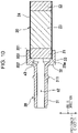
- Fig. 10 is a cross-sectional view of the mouthpiece 30 and the cartridge 20 along the width direction.
- the engagement peripheral portion 33 is thinner at a non-outlet-side part 331 than at an outlet-side part 332. This creates a step 333 at the boundary between the non-outlet-side part 331 and the outlet-side part 332.
- the step 333 is substantially annular in plan view, as viewed in the direction of the axis line O.
- an inner periphery 33i of the non-outlet-side part 331 of the engagement peripheral portion 33 (i.e., an inner periphery of the engagement peripheral portion 33) has a plurality of grooved portions 335 recessed outward in the radial direction.
- adjacent ones of the grooved portions 335 have therebetween a protruding portion 336 protruding inward in the radial direction.
- six grooved portions 335 are substantially equally spaced in the circumferential direction. Note that there may be provided any appropriate number of grooved portions 335.
- the grooved portions 335 may be optional.
- a circle formed by the inner peripheries 33i of the plurality of protruding portions 336 is defined as an imaginary circle A1 (see a two-dot chain line).
- the sum of the lengths of the inner peripheries 33i of the plurality of protruding portions 336 in the circumferential direction is preferably greater than or equal to half the circumference of the imaginary circle A1.
- the engagement peripheral portion 33 has a tapered portion 337 formed at an end thereof on the non-outlet side.
- the tapered portion 337 is gradually inclined outward in the radial direction, with decreasing distance to the non-outlet side.
- the mouthpiece 30 has a flow channel s2 passing therethrough in the direction of the axis line O.
- the flow channel s2 allows vapor from the cartridge 20 to flow therein.
- the engagement peripheral portion 33 of the mouthpiece 30 is fitted to the engagement inner peripheral portion 124 of the protruding cylinder 121 of the mouthpiece supporting member 120.
- the outer periphery 33j of the engagement peripheral portion 33 of the mouthpiece 30 is in contact with an inner periphery 124i of the engagement inner peripheral portion 124 of the mouthpiece supporting member 120.
- the engagement inner peripheral portion 124 of the mouthpiece supporting member 120 is elastically deformed outward in the radial direction, from the state indicated by a two-dot chain line to the state indicated by a solid line, so that the repulsive force biases the engagement peripheral portion 33 of the mouthpiece 30 inward in the radial direction.
- the engagement peripheral portion 33 of the mouthpiece 30 is thus engaged in the protruding cylinder 121 of the mouthpiece supporting member 120.
- the inner periphery (holding section) 33i of the engagement peripheral portion 33 of the mouthpiece 30 is fitted onto (or holds) the first filter portion 21 of the cartridge 20.
- the first filter portion 21 is elastically deformed inward in the radial direction, from the state indicated by a two-dot chain line to the state indicated by a solid line, and is held by the engagement peripheral portion 33 of the mouthpiece 30.
- an end portion 20a of the cartridge 20 on the outlet side is in contact with the step 333 of the engagement peripheral portion 33 of the mouthpiece 30.
- the opening width of the connection between the outlet portion 31 and the base 32 increases toward the non-outlet side from the outlet side.
- the end portion 20a of the cartridge 20 on the outlet side and a surface of the outlet portion 31 of the mouthpiece 30 on the non-outlet side form a space s3 therebetween. This reduces the area obstructed by the end portion 20a of the cartridge 20 on the outlet side and reduces ventilation resistance.
- the first filter portion 21 of the cartridge 20 is in contact with the inner periphery 33i of the engagement peripheral portion 33 of the mouthpiece 30. At the same time, the first filter portion 21 bends outward in the radial direction at the grooved portions 335, and elastically deforms to enter into the grooved portions 335.
- the length of the portion of the cartridge 20 held by the engagement peripheral portion 33 of the mouthpiece 30 (i.e., length along the direction of the axis line O) may be 10% to 30%, or preferably about 20%, of the length of the cartridge 20 along the direction of the axis line O.
- the mouthpiece 30 extends on both sides of the mouthpiece opening 125 in the direction of the axis line O.
- the engagement peripheral portion 33 of the mouthpiece 30 is located on the non-outlet side of the mouthpiece opening 125
- the outlet portion 31 of the mouthpiece 30 is located on the outlet side of the mouthpiece opening 125.
- a configuration is made such that the static frictional force acting between the inner periphery 33i of the engagement peripheral portion 33 of the mouthpiece 30 and the first filter portion 21 of the cartridge 20 is greater than the static frictional force acting between the outer periphery 33j of the engagement peripheral portion 33 of the mouthpiece 30 and the engagement inner peripheral portion 124 of the mouthpiece supporting member 120.
- the cap 40 is disposed to cover the mouthpiece 30.
- the cap 40 includes an outer cap portion 41 and an end cap portion 42.
- the outer cap portion 41 is formed substantially in the shape of a rectangular cylinder centered on the axis line O.
- the end cap portion 42 is disposed at an end of the outer cap portion 41 on the outlet side.
- the cartridge 20 is inserted through the mouthpiece opening 125 into the cartridge supporting member 140.
- the mouthpiece 30 is fitted into the mouthpiece supporting member 120, the cartridge 20 is held in place by the mouthpiece 30.
- the user pulls the mouthpiece 30 out toward the outlet side, with fingers placed on the face of the finger hold 311 of the mouthpiece 30 on the non-outlet side.
- the cartridge 20, which is held by the mouthpiece 30, is pulled out together with the mouthpiece 30.
- the outer periphery 33j of the engagement peripheral portion 33 of the mouthpiece 30 and the engagement inner peripheral portion 124 of the mouthpiece supporting member 120 are brought out of engagement.
- This allows the cartridge 20 held by the inner periphery 33i of the engagement peripheral portion 33 of the mouthpiece 30 to be detached from the housing 11 together with the mouthpiece 30, eliminates the need for the user to individually detach the cartridge 20 and the mouthpiece 30, and facilitates replacement of the cartridge 20.
- the mouthpiece 30 is detached from the housing 11 by simply holding the outlet portion 31 of the mouthpiece 30 protruding outward from the mouthpiece opening 125 of the housing 11. The mouthpiece 30 can thus be detached easily.
- the cartridge 20 does not protrude outward from the mouthpiece opening 125 of the housing 11. This prevents the user from accidentally touching the cartridge 20.
- the maximum static frictional force acting between the inner periphery 33i of the engagement peripheral portion 33 of the mouthpiece 30 and the outer periphery of the first filter portion 21 of the cartridge 20 is greater than the maximum static frictional force acting between the inner periphery of the peripheral portion 142 of the cartridge supporting member 140 and the outer periphery of the remaining portion of the cartridge 20 (i.e., portion of the cartridge 20 in contact with the inner periphery of the peripheral portion 142 of the cartridge supporting member 140). Therefore, when the mouthpiece 30 is detached from the housing 11, the cartridge 20 can be reliably pulled out together with the mouthpiece 30.
- the cartridge 20 is held by fitting the inner periphery 33i of the engagement peripheral portion 33 of the mouthpiece 30 onto first filter portion 21 of the cartridge 20.
- the cartridge 20 can thus be easily held by the mouthpiece 30.
- the cartridge 20 elastically deforms to allow the outer periphery of the cartridge 20 to enter into the grooved portions 335 in the inner periphery 33i of the engagement peripheral portion 33 of the mouthpiece 30.
- the inner periphery 33i of the engagement peripheral portion 33 of the mouthpiece 30 firmly holds the cartridge 20.
- the plurality of grooved portions 335 are equally spaced in the circumferential direction. Therefore, a repulsive force generated when the outer periphery of the cartridge 20 bends is uniformly distributed in the circumferential direction. This allows the inner periphery 33i of the engagement peripheral portion 33 of the mouthpiece 30 to hold the cartridge 20 with uniform force throughout its circumference.
- the sum of the lengths of the inner peripheries 33i of the plurality of protruding portions 336 in the circumferential direction is, for example, greater than or equal to half the circumference of the imaginary circle A1. This provides a sufficient area of contact between the protruding portions 336 and the outer periphery of the cartridge 20, and secures a sufficient force with which the inner peripheries 33i of the engagement peripheral portion 33 of the mouthpiece 30 holds the cartridge 20.
- the outer periphery 33j of the engagement peripheral portion 33 of the mouthpiece 30 is in contact with the inner periphery 124i of the engagement inner peripheral portion 124 of the mouthpiece supporting member 120 formed along the direction of the axis line O. This reduces displacement (or shaking) of the mouthpiece 30 in a direction intersecting the direction of the axis line O, with respect to the mouthpiece opening 125 of the housing 11, and facilitates attachment and detachment of the mouthpiece 30 along the direction of the axis line O.
- the outer periphery 33j of the engagement peripheral portion 33 of the mouthpiece 30 is biased inward in the radial direction by the housing 11, so that the mouthpiece 30 is prevented from accidentally falling off the housing 11.
- the outer periphery of the mouthpiece 30 has the finger hold 311 on which the user can place fingers. This allows the user to attach and detach the mouthpiece 30 with fingers placed on the finger hold 311, and improves attachability and detachability of the mouthpiece 30.
- a cross-section orthogonal to the direction of the axis line O has a flattened shape. Therefore, when the user puts the mouthpiece 30 in the mouth, with the short-side direction of the mouthpiece 30 being the up-down direction, the upper and lower lips are not far apart. This reduces the flow of air into the mouth through the gap between the mouthpiece 30 and each end of the lips in the right and left direction.
- the controller 152 is capable of controlling the heating temperature of the heater 16 in such a way that components contained in the flavor portion 23 are heated at a temperature lower than the temperature at which the components are aerosolized. For example, when the ambient temperature is room temperature, the flavor component and other components of the flavor portion 23 are aerosolized when heated at about 150°C or higher.
- the controller 152 is capable of controlling the heating temperature in such a way that the flavor portion 23 is heated below 150°C. This allows the flavor component to be delivered in a substantially invisible state to the user. By heating the flavor portion 23 at a lower temperature, it is possible to slow down the exhaustion of the flavor component and others contained in the flavor portion 23, and thus to deliver the flavor component to the user over a long period of time.
- the heating temperature at which to heat the flavor portion 23 is preferably from 100°C to 120°C.
- a mouthpiece 30A is engaged in a cartridge container 130A.
- An outer periphery 34j of the engagement peripheral portion 34 has an engagement annular portion (engagement section) 35 protruding outward in the radial direction.
- the engagement annular portion 35 is provided over the entire circumference of the engagement peripheral portion 34 in the circumferential direction.
- the engagement annular portion 35 does not necessarily need to be provided over the entire circumference in the circumferential direction, as long as it is provided at points corresponding to the engagement recesses 134 in the cartridge container 130A.
- the outlet portion 31 of the mouthpiece 30A does not have the finger hold 311 described in the first embodiment.
- the engagement annular portion 35 of the mouthpiece 30A is engaged in the engagement recesses 134 in the cartridge container 130A.
- the cartridge 20 is inserted through the mouthpiece opening 125 into the cartridge supporting member 140.
- the engagement annular portion 35 of the mouthpiece 30A is brought into contact with portions of the extending walls 133 of the cartridge container 130A on the outlet side of the engagement recesses 134, and the extending walls 133 of the cartridge container 130A are elastically deformed outward in the radial direction.
- the engagement annular portion 35 of the mouthpiece 30A is fitted into the engagement recesses 134.
- the mouthpiece 30A holds the cartridge 20.
- the user holds the mouthpiece 30A and pulls it out toward the outlet side.
- the cartridge 20, which is held by the mouthpiece 30A is pulled out together with the mouthpiece 30A.
- the engagement annular portion 35 of the mouthpiece 30A and the engagement recesses 134 in the cartridge container 130A are brought out of engagement. This allows the cartridge 20 held by the inner periphery of the engagement peripheral portion 34 of the mouthpiece 30A to be detached from the housing 11 together with the mouthpiece 30A, eliminates the need for the user to individually detach the cartridge 20 and the mouthpiece 30A, and facilitates replacement of the cartridge 20.
- the cylindrical container member 131 of the cartridge container 130B has an extending annular wall 139 extending on the outlet side of the cartridge supporting wall 132.
- the extending annular wall 139 is provided over the entire circumference of the cylindrical container member 131 in the circumferential direction.
- the extending annular wall 139 has protrusion engagement grooves 134a. There are provided four protrusion engagement grooves 134a spaced apart in the circumferential direction of the extending annular wall 139. It is only required that the protrusion engagement grooves 134a be formed to correspond to the respective engagement protrusions 36.
- the protrusion engagement grooves 134a are each composed of an insertion recess (first groove) 134b and the engagement hole (second groove) 134c.
- the cartridge 20 is inserted through the mouthpiece opening 125 into the cartridge supporting member 140.
- the mouthpiece 30B is placed in such a manner that each engagement protrusion 36 of the mouthpiece 30B is on the same axis as a corresponding one of the insertion recesses 134b in the cartridge container 130B.
- the mouthpiece 30B is rotated in one direction about the axis line O to engage the engagement protrusion 36 in the engagement hole 134c.
- the mouthpiece 30B holds the cartridge 20.
- the user rotates the mouthpiece 30B in the opposite direction about the axis line O (i.e., in the direction opposite that when the mouthpiece 30B is attached) to allow the engagement protrusion 36 to be positioned at the insertion recess 134b, and pulls the mouthpiece 30B out toward the outlet side.
- the cartridge 20, which is held by the mouthpiece 30B is pulled out together with the mouthpiece 30B.
- the engagement protrusions 36 of the mouthpiece 30B and the engagement holes 134c in the mouthpiece supporting member 120 are brought out of engagement. This allows the cartridge 20 held by the inner periphery of the engagement peripheral portion 34 of the mouthpiece 30B to be detached from the housing 11 together with the mouthpiece 30B, eliminates the need for the user to individually detach the cartridge 20 and the mouthpiece 30B, and facilitates replacement of the cartridge 20.
- the engagement protrusions 36 of the mouthpiece 30B are engaged in the engagement holes 134c in the mouthpiece supporting member 120.
- the mouthpiece 30B needs to be rotated in the circumferential direction before the engagement protrusions 36 are moved along the insertion recesses 134b in the mouthpiece supporting member 120. This prevents accidental disengagement of the engagement protrusions 36 and the engagement holes 134c.
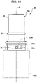
- Fig. 17 is a lateral view of a mouthpiece of a flavor inhalation system according to modified embodiment 1.
- Fig. 18 is a lateral view of a mouthpiece of a flavor inhalation system according to modified embodiment 2.
- Fig. 19 is a lateral view of a mouthpiece of a flavor inhalation system according to modified embodiment 3.
- a mouthpiece 30C of an inhaler which is an example of the flavor inhalation system according to modified embodiment 1, has two finger holds 312 spaced apart on the outer periphery of the outlet portion 31 ( FIG. 17 shows only one finger hold 312).
- the finger holds 312 are each disposed on a surface along the direction of the long side of the outlet portion 31 (i.e., along the front-back direction).
- a mouthpiece 30D of an inhaler which is an example of the flavor inhalation system according to modified embodiment 2, has two finger holds 313 spaced apart on the outer periphery of the outlet portion 31.
- the finger holds 313 are each disposed on a surface along the direction of the short side of the outlet portion 31 (i.e., along the width direction).
- a mouthpiece 30E of an inhaler which is an example of the flavor inhalation system according to modified embodiment 3, has finger holds 314 recessed inward in the radial direction from the outer periphery of the outlet portion 31.
- the finger holds 314 are each provided in a surface along the direction of the short side of the outlet portion 31 (i.e., along the width direction).
- the finger holds 314 may each be provided in a surface along the direction of the long side of the outlet portion 31 (i.e., along the front-back direction).
- the lengths of the finger holds 312 to 314 along the direction of the axis line O may be appropriately determined. There may be provided a plurality of finger holds 312 to 314 along the direction of the axis line O.
- the mouthpieces 30C to 30D according to modified embodiments 1 to 3 have, on the outer peripheries thereof, the finger holds 312 to 314 on which the user can place fingers. This allows the user to attach or detach the mouthpieces 30C to 30D with fingers placed on the finger holds 312 to 314, and thus improves attachability and detachability of the mouthpieces 30C to 30D.
- the configuration is not limited to this.
- the cartridge 20 may protrude beyond the mouthpiece opening 125 toward the outlet side.
- the mouthpiece 30 may be configured either to hold only a portion of the cartridge 20 protruding from the mouthpiece opening 125 toward the outlet side, or to hold both the portion of the cartridge 20 protruding from the mouthpiece opening 125 toward the outlet side and the portion of the cartridge 20 protruding from the mouthpiece opening 125 toward the non-outlet side.
- the pull-out retainer may be a jig that is specifically designed for replacing the cartridge 20.
- the configuration is not limited to this.
- the mouthpiece 30 may have protrusions that are capable of being engaged with the cartridge 20, so that the cartridge 20 can be pulled out from the housing 11 together with the mouthpiece 30.
Landscapes
- Disinfection, Sterilisation Or Deodorisation Of Air (AREA)
Abstract
Description
- The present invention relates to a flavor inhalation system, a mouthpiece, and a cartridge.
- Flavor inhalation systems have been known, which are configured to heat and atomize vapor, so that the user can inhale the vapor and enjoy the flavor.
- For example,
Patent Literature 1 discloses an aerosol-generating system that includes an aerosol-generating device and a mouthpiece. A cartridge is placed in a housing of the aerosol-generating device, and the mouthpiece is disposed to cover an end portion of the cartridge. - PTL 1:
Japanese Unexamined Patent Application Publication (Translation of PCT Application) No. 2018-528788 - In the related art described above, replacing the cartridge after use involves detaching the mouthpiece, pulling the cartridge out of the housing, inserting a new cartridge into the housing, and attaching the mouthpiece. A problem is that it is cumbersome to detaching the cartridge and the mouthpiece individually.
- The present invention provides a flavor inhalation system, a mouthpiece, and a cartridge that facilitate replacement of the cartridge.
- (1) To achieve the object described above, a flavor inhalation system according to an aspect of the present embodiment includes a housing and a pull-out retainer. The housing extends in an axial direction and has an opening formed at a first end portion thereof in the axial direction. The housing has therein a storage space communicating with the opening. The housing stores, in the storage space, a cartridge containing a flavor component. The pull-out retainer includes an engagement section and a holding section. The engagement section is engaged in the opening. The holding section is configured to hold the cartridge.
- In the present aspect, when the pull-out retainer is detached from the housing to replace the cartridge, the engagement section of the pull-out retainer and the opening of the housing are brought out of engagement. This allows the cartridge held by the holding section of the pull-out retainer to be detached from the housing together with the pull-out retainer, eliminates the need to individually detach the cartridge and the pull-out retainer, and facilitates replacement of the cartridge.
- (2) In the flavor inhalation system according to the aspect (1), the pull-out retainer is configured to extend on both sides of the opening in the axial direction while being engaged in the opening.
- In the present aspect, the pull-out retainer can be detached from the housing by simply holding a portion of the pull-out retainer protruding outward from the opening of the housing. The pull-out retainer can thus be detached easily.
- (3) In the flavor inhalation system according to the aspect (1) or (2), the pull-out retainer is a mouthpiece having a flow channel configured to allow vapor from the cartridge to flow therein.
- In the present aspect, when the mouthpiece is detached from the housing, the cartridge is detached from the housing together with the mouthpiece.
- (4) In the flavor inhalation system according to any one of the aspects (1) to (3), the engagement section is a protrusion protruding in a radial direction outward from an outer periphery of the pull-out retainer. An inner periphery of the housing has a first groove portion and a second groove portion. The first groove portion is recessed outward in the radial direction and extends from the first end portion in the axial direction. The second groove portion is recessed outward in the radial direction and extends in one circumferential direction from an end portion of the first groove opposite the first end portion. The engagement section is engaged in the second groove.
- In the present aspect, the engagement section (protrusion) is engaged in the second groove in the housing. To bring the engagement section and the second groove out of engagement, the pull-out retainer needs to be rotated in the circumferential direction before the engagement section is moved along the first groove. This prevents accidental disengagement of the engagement section and the second groove.
- (5) In the flavor inhalation system according to any one of the aspects (1) to (4), the storage space is capable of storing the cartridge in such a way that the cartridge does not protrude outward from the opening.
- In the present aspect, where the cartridge does not protrude outward from the opening of the housing, the user is prevented from accidentally touching the cartridge.
- (6) In the flavor inhalation system according to any one of the aspects (1) to (5), a static frictional force acting between the holding section and the cartridge is greater than a static frictional force acting between an inner wall of the storage space and the cartridge.
- In the present aspect, a static frictional force acting between the holding section of the pull-out retainer and the cartridge is greater than a static frictional force acting between the inner wall of the storage space and the cartridge. Therefore, when the pull-out retainer is detached from the housing, the cartridge can be reliably pulled out together with the pull-out retainer.
- (7) In the flavor inhalation system according to any one of the aspects (1) to (6), the holding section is configured to be fitted onto one end portion of the cartridge extending in the axial direction.
- In the present aspect, where the holding section is fitted onto the one end portion of the cartridge extending in the axial direction, the cartridge can be easily held by the holding section.
- (8) In the flavor inhalation system according to the aspect (7), an inner periphery of the holding section has a grooved portion recessed outward in the radial direction.
- In the present aspect, the cartridge elastically deforms in such a way as to allow the outer periphery of the cartridge to enter into the grooved portion in the holding section. Thus, with a repulsive force generated when the outer periphery of the cartridge bends, the holding section firmly holds the cartridge.
- (9) In the flavor inhalation system according to the aspect (8), a plurality of grooved portions are equally spaced in a circumferential direction.
- In the present aspect, where a plurality of grooved portions are equally spaced in the circumferential direction, a repulsive force generated when the outer periphery of the cartridge bends is uniformly distributed in the circumferential direction. This allows the holding section to hold the cartridge with uniform force throughout its circumference.
- (10) In the flavor inhalation system according to the aspect (9), adjacent ones of the grooved portions have therebetween a protruding portion protruding inward in the radial direction. A sum of lengths of inner peripheries of a plurality of protruding portions in the circumferential direction is greater than or equal to half a circumference of an imaginary circle defined by the inner peripheries of the plurality of protruding portions.
- In the present aspect, the sum of the lengths of the inner peripheries of the plurality of protruding portions in the circumferential direction is greater than or equal to half the circumference of the imaginary circle described above. This provides a sufficient area of contact between the protruding portions and the outer periphery of the cartridge, and secures a sufficient force with which the holding section holds the cartridge.
- (11) In the flavor inhalation system according to any one of the aspects (1) to (10), the engagement section is configured as an engagement surface having a planar shape. The opening is provided with a contact surface formed along the axial direction and capable of being in contact with the engagement surface.
- In the present aspect, the engagement section is in contact with the contact surface formed in the opening of the housing along the axial direction. This reduces displacement (or shaking) of the pull-out retainer in a direction intersecting the axial direction with respect to the opening of the housing, and facilitates attachment and detachment of the pull-out retainer along the axial direction.
- (12) In the flavor inhalation system according to any one of the aspects (1) to (11), the housing biases the engagement section inward in the radial direction.
- In the present aspect, where the engagement section is biased inward in the radial direction by the housing, the pull-out retainer is prevented from accidentally falling off the housing.
- (13) In the flavor inhalation system according to any one of the aspects (1) to (12), an outer periphery of the pull-out retainer has a finger hold on which a user can place fingers.
- In the present aspect, the outer periphery of the pull-out retainer has the finger hold on which the user can place fingers. This allows the user to attach and detach the pull-out retainer with fingers placed on the finger hold, and improves attachability and detachability of the pull-out retainer.
- (12) A mouthpiece according to another aspect of the present embodiment is detachably attached to a housing that extends in an axial direction, has an opening formed at a first end portion thereof in the axial direction, and has therein a storage space communicating with the opening and storing a cartridge containing a flavor component. The mouthpiece includes an engagement section and a holding section. The engagement section is engaged in the opening, and the holding section is configured to hold the cartridge. The mouthpiece has a flow channel configured to allow vapor from the cartridge to flow therein.
- In the present aspect, when the mouthpiece is detached from the housing to replace the cartridge, the engagement section of the mouthpiece and the opening of the housing are brought out of engagement. This allows the cartridge held by the holding section of the mouthpiece to be detached from the housing together with the mouthpiece, eliminates the need for the user to individually detach the cartridge and the mouthpiece, and facilitates replacement of the cartridge.
- (15) In the mouthpiece according to the aspect (15), a cross-section orthogonal to the axial direction has a flattened shape.
- In the present aspect, a cross-section orthogonal to the axial direction has a flattened shape. Therefore, when the user puts the mouthpiece in the mouth, with the short-side direction of the mouthpiece being the up-down direction, the upper and lower lips are not far apart. This reduces the flow of air into the mouth through the gap between the mouthpiece and each end of the lips in the right and left direction.
- (16) A cartridge according to another aspect of the present embodiment is a cartridge used in a flavor inhalation system that includes a housing and a pull-out retainer. The housing extends in an axial direction and has an opening formed at a first end portion thereof in the axial direction. The housing is internally formed to communicate with the opening. The cartridge includes a flavor portion and a filter portion. The flavor portion has a flavor component. The filter portion is configured to allow vapor produced by heating the flavor portion to pass therethrough. The filter portion is held by a holding section of the pull-out retainer.
- In the present aspect, when the pull-out retainer is detached from the housing to replace the cartridge, the engagement section of the pull-out retainer and the opening of the housing are brought out of engagement. This allows the cartridge including the filter portion held by the holding section of the pull-out retainer to be detached from the housing together with the pull-out retainer, eliminates the need for the user to individually detach the cartridge and the pull-out retainer, and facilitates replacement of the cartridge.
- An aspect of the present embodiment facilitates replacement of the cartridge.
-
- [
Fig. 1] Fig. 1 is a perspective view of a flavor inhalation system according to a first embodiment. - [
Fig. 2] Fig. 2 is a perspective view of the flavor inhalation system according to the first embodiment, with a cap detached therefrom. - [
Fig. 3] Fig. 3 is a cross-sectional view taken along line III-III inFig. 2 . - [
Fig. 4] Fig. 4 is a perspective view of a mouthpiece supporting member of the flavor inhalation system according to the first embodiment. - [
Fig. 5] Fig. 5 is an enlarged view of part A inFig. 3 . - [
Fig. 6] Fig. 6 is a perspective view of a mouthpiece of the flavor inhalation system according to the first embodiment, as viewed from the outlet side. - [
Fig. 7] Fig. 7 is a perspective view of the mouthpiece of the flavor inhalation system according to the first embodiment, as viewed from the non-outlet side. - [
Fig. 8] Fig. 8 is a plan view of the mouthpiece of the flavor inhalation system according to the first embodiment, as viewed from the outlet side. - [
Fig. 9] Fig. 9 is a plan view of the mouthpiece of the flavor inhalation system according to the first embodiment, as viewed from the non-outlet side. - [
Fig. 10] Fig. 10 is a cross-sectional view of the mouthpiece and a cartridge of the flavor inhalation system according to the first embodiment. - [
Fig. 11] Fig. 11 is a cross-sectional view of a main part of a flavor inhalation system according to a second embodiment. - [
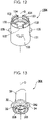
Fig. 12] Fig. 12 is a perspective view of a cartridge container of the flavor inhalation system according to the second embodiment. - [
Fig. 13] Fig. 13 is a perspective view of a mouthpiece of the flavor inhalation system according to the second embodiment. - [
Fig. 14] Fig. 14 is a lateral view of a mouthpiece of a flavor inhalation system according to a third embodiment. - [
Fig. 15] Fig. 15 is a perspective view of the mouthpiece of the flavor inhalation system according to the third embodiment. - [
Fig. 16] Fig. 16 is a perspective view of a cartridge container of the flavor inhalation system according to the third embodiment. - [
Fig. 17] Fig. 17 is a lateral view of a mouthpiece of a flavor inhalation system according to modifiedembodiment 1. - [
Fig. 18] Fig. 18 is a lateral view of a mouthpiece of a flavor inhalation system according to modifiedembodiment 2. - [
Fig. 19] Fig. 19 is a lateral view of a mouthpiece of a flavor inhalation system according to modified embodiment 3. - Embodiments of the present invention will now be described with reference to the drawings. In the drawings referred to below, the same or corresponding component elements are assigned the same reference numerals and redundant description will be omitted.
-
Fig. 1 is a perspective view of a flavor inhalation system according to a first embodiment. - As illustrated in
Fig. 1 , aninhaler 1, which is an example of the flavor inhalation system according to the first embodiment, is a so-called heated tobacco product. Theinhaler 1 heats tobacco leaves to produce vapor, and allows the user to inhale the vapor and enjoy flavor of the tobacco leaves. -
Fig. 2 is a perspective view of theinhaler 1, with acap 40 detached therefrom. - As illustrated in
Fig. 2 , theinhaler 1 includes amain unit 10, acartridge 20, a mouthpiece (pull-out retainer) 30, and the cap 40 (seeFig. 1 ). Thecartridge 20 according to the embodiments and modified embodiments typically has an outer periphery made of paper and is either elastic or flexible. The configuration of thecartridge 20 is not limited to this. Any consumable material configured to be capable of being attached to and detached from theinhaler 1 can be used as thecartridge 20. - The outer shape of the
inhaler 1 is a substantially rectangular columnar shape centered on the axis line O. Themain unit 10, thecartridge 20, themouthpiece 30, and thecap 40 are arranged on the axis line O. In the following description, in the direction of the axis line O (i.e., direction along the axis line O, or axial direction), one side of themain unit 10 to which themouthpiece 30 is disposed is referred to as an outlet side, and one side of themouthpiece 30 to which themain unit 10 is disposed is referred to as a non-outlet side. In plan view as viewed in the direction of the axis line O, a direction intersecting the axis line O is referred to as a radial direction. A radial direction toward the axis line O is referred to as an inward direction, and a radial direction away from the axis line O is referred to as an outward direction. A direction circling around the axis line O is referred to as a circumferential direction. In the present specification, the term "direction" refers to two directions, each of which is referred to as "side". -
Fig. 3 is a cross-sectional view taken along line III-III inFig. 2 . As illustrated inFig. 3 , themain unit 10 includes a housing 11, apower supply unit 15, and aheater 16. The housing 11 includes ahousing body 110, amouthpiece supporting member 120, and acartridge container 130. - The
housing body 110 includes anouter housing 111 and abottom cap 116. - The
outer housing 111 is formed substantially in the shape of a rectangular cylinder centered on the axis line O. Theouter housing 111 constitutes the outer surface of theinhaler 1. Theouter housing 111 may be of any appropriate shape that will extend in the direction of the axis line O. - The
outer housing 111 has an outlet-side opening 111a formed at an end portion thereof on the outlet side and passing therethrough in the direction of the axis line O. Theouter housing 111 has anon-outlet side opening 111b formed at an end portion thereof on the non-outlet side and passing therethrough in the direction of the axis line O. Theouter housing 111 has aswitch opening 111c formed at a portion thereof in the circumferential direction and passing therethrough in the radial direction. Theswitch opening 111c has aswitch 112 therein. - In the present embodiment, a radial direction that connects the axis line O and the
switch opening 111c is defined as a front-back direction. In this case, one side of the axis line O to which theswitch opening 111c is disposed is defined as a front side, and the other side of the axis line O opposite theswitch opening 111c is defined as a back side. - The
bottom cap 116 is disposed in the non-outlet side opening 111b of theouter housing 111. Thebottom cap 116 is substantially rectangular in plan view, as viewed in the direction of the axis line O. Thebottom cap 116 is configured to close the non-outlet side opening 111b of theouter housing 111. Thebottom cap 116 may be of any appropriate shape that will close the non-outlet side opening 111b of theouter housing 111. - The
housing body 110 has therein an innercylindrical member 117. The innercylindrical member 117 extends in the direction of the axis line O and is formed substantially in the shape of a rectangular cylinder. The innercylindrical member 117 is formed by a pair of halves coupled together along the direction of the axis line O. The overall length of the inner cylindrical member 117 (i.e., length along the direction of the axis line O) is shorter than the overall length of theouter housing 111. The innercylindrical member 117 may be of any appropriate shape. - The inner
cylindrical member 117 is internally provided with a partition 118 that separates a space for accommodating a battery 151 (described below) from a space for accommodating theheater 16. - The partition 118 has an outlet-
side partition portion 118a and alateral partition portion 118b. This reduces the flow of air heated by theheater 16 into the space for accommodating thebattery 151. Accordingly, a rise in the temperature of thebattery 151 is reduced. - The outlet-
side partition portion 118a is disposed to the outlet side of thebattery 151. Thelateral partition portion 118b is disposed to cover the exterior of thebattery 151 in the circumferential direction. - The
mouthpiece supporting member 120 is disposed in the outlet-side opening 111a of theouter housing 111. -
Fig. 4 is a perspective view of themouthpiece supporting member 120. - As illustrated in
Fig. 4 , themouthpiece supporting member 120 includes a protrudingcylinder 121, afitting cylinder 126, and lockingpieces 129. - The protruding
cylinder 121 includes an innerannular portion 122, an innerperipheral portion 123, and an engagement innerperipheral portion 124. - The outer shape of the inner
annular portion 122 is substantially rectangular in plan view, as viewed in the direction of the axis line O. The innerannular portion 122 may be of any appropriate shape, and is not limited to being substantially rectangular in plan view. - The inner
annular portion 122 has a mouthpiece opening (opening) 125 passing therethrough in the direction of the axis line O. In other words, themouthpiece supporting member 120 has the mouthpiece opening 125 formed at an end portion thereof on the outlet side and passing therethrough in the direction of the axis line O. - The
mouthpiece opening 125 is substantially rectangular in plan view, as viewed in the direction of the axis line O. Note that themouthpiece opening 125 may be of any appropriate shape, and is not limited to being substantially rectangular in plan view. -
Fig. 5 is an enlarged view of part A inFig. 3 . - As illustrated in
Fig. 5 , the innerperipheral portion 123 extends from the outer edge of the innerannular portion 122 toward the non-outlet side. The innerperipheral portion 123 is disposed over the entire circumference of the innerannular portion 122 in the circumferential direction. - The engagement inner
peripheral portion 124 extends from the mouthpiece opening 125 in the innerannular portion 122 toward the non-outlet side. The engagement innerperipheral portion 124 is disposed over the entire circumference of the mouthpiece opening 125 in the circumferential direction. - A direction orthogonal to the direction of the axis line O and the front-back direction is defined as a width direction.
- The engagement inner
peripheral portion 124 is formed in a plate shape. Apart 124a of the engagement innerperipheral portion 124 along the width direction is disposed with the plate thickness thereof being in the front-back direction. Apart 124b of the engagement innerperipheral portion 124 along the front-back direction (seeFig. 4 ) is disposed with the plate thickness thereof being in the width direction. An inner periphery (contact surface) 124i of the engagement innerperipheral portion 124 is formed in a planar shape along the direction of the axis line O. - As illustrated in
Fig. 4 , the engagement innerperipheral portion 124 disposed along a substantially rectangular shape in plan view, as viewed in the direction of the axis line O, has aslit 124s at a corner thereof. Theslit 124s is formed to extend from an end portion of the engagement innerperipheral portion 124 on the non-outlet side toward the outlet side. Theslit 124s penetrates the engagement innerperipheral portion 124 in the direction of the plate thickness thereof. This allows the engagement innerperipheral portion 124 to elastically deform in the direction of the plate thickness thereof. - The
fitting cylinder 126 includes an outerannular portion 127 and an outerperipheral portion 128. - As illustrated in
Fig. 5 , the outerannular portion 127 extends outward in the radial direction, from an end of the innerperipheral portion 123 of the protrudingcylinder 121 on the non-outlet side. The outerannular portion 127 is disposed over the entire circumference of the innerperipheral portion 123 in the circumferential direction. The outer shape of the outerannular portion 127 is substantially rectangular in plan view, as viewed in the direction of the axis line O (seeFig. 4 ). The outerannular portion 127 may have any outer shape that will fit in the outlet-side opening 111a of theouter housing 111. - A surface of the outer
annular portion 127 on the outlet side is disposed to be flush with the end portion of theouter housing 111 on the outlet side. The protrudingcylinder 121 is disposed to protrude toward the outlet side from the outlet-side opening 111a of theouter housing 111. - The outer
peripheral portion 128 extends from the outer edge of the outerannular portion 127 toward the non-outlet side. The outerperipheral portion 128 is disposed over the entire circumference of the outerannular portion 127 in the circumferential direction. - The outer
peripheral portion 128 is inserted through the outlet-side opening 111a of theouter housing 111 and fit to a portion of theouter housing 1 1 1 on the outlet side. In other words, the outerperipheral portion 128 is disposed in contact with the inner periphery of theouter housing 111 on the outlet side. - As illustrated in
Fig. 4 , apart 128b of the outerperipheral portion 128 along the front-back direction is provided with thelocking piece 129 extending toward the non-outlet side. - The
locking piece 129 has alocking hole 129h passing therethrough in the width direction. A protrusion (not shown) on the outer periphery of the inner cylindrical member 117 (seeFig. 5 ) is locked in thelocking hole 129h. - The
locking piece 129 has a lockingprotrusion 129c on the non-outlet side of thelocking hole 129h. The lockingprotrusion 129c protrudes outward in the width direction (i.e., protrudes in a direction away from the axis line O). The lockingprotrusion 129c is locked in a recess (not shown) formed in the inner periphery of the outer housing 111 (seeFig. 5 ). - As illustrated in
Fig. 5 , thecartridge container 130 is disposed inside the innercylindrical member 117, on the outlet side of the outlet-side partition portion 118a. - The
cartridge container 130 is formed by assembling acylindrical container member 131 and abottom member 136 together. Thecylindrical container member 131 is disposed on the outlet side of thebottom member 136. - The
cylindrical container member 131 is formed in the shape of a circular cylinder centered on the axis line O. Thecylindrical container member 131 may be of any appropriate shape that will extend in the direction of the axis line O. - The
cylindrical container member 131 has acartridge supporting wall 132 formed at an end portion thereof on the outlet side and extending inward in the radial direction. Thecartridge supporting wall 132 is annularly shaped in plan view, as viewed in the direction of the axis line O. Thecartridge supporting wall 132 is preferably shaped to be capable of being in contact with the outer periphery of thecartridge 20 and may be of any appropriate shape. - The
bottom member 136 has acontainer recess 137a formed toward the non-outlet side. Thecontainer recess 137a is formed in a circular shape in plan view, as viewed in the direction of the axis line O. - The
outer housing 111 has aventilation opening 111d formed on the front side thereof and passing therethrough in the front-back direction. Thebottom member 136 has abottom portion 137b at an end portion thereof on the non-outlet side, and an inflow-side opening 138a communicating with theventilation opening 111d is formed on the front side of thebottom portion 137b. The bottom portion 137 has an outflow-side opening 138b formed at a bottom of thecontainer recess 137a (i.e., formed in a surface orthogonal to the direction of the axis line O). Aventilation passage 138 is formed to allow the inflow-side opening 138a to communicate with the outflow-side opening 138b. - The
cartridge container 130 includes therein acartridge supporting member 140. Thecartridge supporting member 140 has a supportingbottom 141, aperipheral portion 142, and aflange 143. For example, thecartridge supporting member 140 is formed of a material of high thermal conductivity, such as stainless steel. - The supporting
bottom 141 is disposed along the bottom of thecontainer recess 137a in thecartridge container 130. The outer shape of the supportingbottom 141 is circular in plan view, as viewed in the direction of the axis line O. The supportingbottom 141 has aventilation hole 141h passing therethrough in the direction of the axis line O. Theventilation hole 141h is formed in a circular shape centered on the axis line O in plan view, as viewed in the direction of the axis line O. Note that the supportingbottom 141 and theventilation hole 141h may be of any appropriate shapes. - An elastic O-
ring 149a is disposed between the supportingbottom 141 of thecartridge supporting member 140 and the bottom of thecontainer recess 137a. - The
peripheral portion 142 extends from the edge of the supportingbottom 141 toward the outlet side. Theperipheral portion 142 is formed in the shape of a circular cylinder centered on the axis line O. - The
flange 143 extends outward in the radial direction, from an end of theperipheral portion 142 on the outlet side. Theflange 143 is annularly shaped in plan view, as viewed in the direction of the axis line O. Theflange 143 is disposed on the non-outlet side of thecartridge supporting wall 132 of thecartridge container 130. - An elastic O-
ring 149b is disposed between theflange 143 of thecartridge supporting member 140 and thecartridge supporting wall 132 of thecartridge container 130. - The
cartridge supporting member 140 has therein a cartridge storage space (storage space) s1 capable of storing thecartridge 20. The cartridge storage space s1 communicates with the mouthpiece opening 125 in themouthpiece supporting member 120. - The
cartridge supporting member 140 is provided with a sensor (not shown), for example, at the supportingbottom 141. The sensor may be, for example, a temperature sensor or a gas component concentration sensor (chemical sensor). The temperature sensor is configured to measure or estimate the temperature of vapor containing a flavor component released from a flavor portion 23 (described below) of thecartridge 20. The gas component concentration sensor is configured to measure or estimate the concentration of vapor containing a flavor component released from theflavor portion 23 of thecartridge 20. - As illustrated in
Fig. 3 , thepower supply unit 15 is formed by mounting, for example, thebattery 151, acontroller 152, and theheater 16 on the innercylindrical member 117. - The
battery 151 inside the innercylindrical member 117 is disposed on the non-outlet side of the outlet-side partition portion 118a. Thebattery 151 is formed in the shape of a circular column centered on an axis parallel to the axis line O. Thebattery 151 is a chargeable and dischargeable secondary battery. For example, thebattery 151 may be a lithium-ion battery. Thebattery 151 may be of any appropriate shape. - The
controller 152 inside the innercylindrical member 117 is disposed on the front side of thelateral partition portion 118b. Thecontroller 152 is disposed between thelateral partition portion 118b and the front side of theouter housing 111. Thebattery 151 and theheater 16 are electrically connected through thecontroller 152 by a wire (not shown). - The
controller 152 includesswitch elements 152a at positions corresponding to theswitch 112 disposed on the front side of theouter housing 111. Thecontroller 152 controls thebattery 151 and theheater 16 in accordance with the operation of theswitch 112. - The
controller 152 is configured to control current flowing from thebattery 151 to theheater 16. This makes it possible to control the heating temperature at which to heat theflavor portion 23 of thecartridge 20. - As illustrated in
Fig. 5 , theheater 16 is disposed along the outer periphery of theperipheral portion 142 of thecartridge supporting member 140. Theheater 16 is disposed throughout the outer periphery of theperipheral portion 142. For example, theheater 16 is constituted by a film heater. The film heater includes a pair of film substrates and a resistance heating element interposed therebetween. The film substrates are preferably made of a material having high heat resistance and high electrical insulation properties. For example, theheater 16 is configured from a polyimide film heater. The resistance heating element is preferably made of any one or more of metal materials, such as copper, nickel alloy, chromium alloy, stainless steel, and platinum-rhodium alloy. For example, the resistance heating element is constituted by a stainless steel substrate. The resistance heating element, which is connected by a flexible printed circuit (FPC) to a power supply, may be copper-plated at the point of connection and the lead portion. - A
heat insulating material 17 is disposed along the outer periphery of theheater 16. Theheat insulating material 17 may be disposed throughout the outer periphery of theheater 16, or may be disposed only on part of the outer periphery of theheater 16. Theheat insulating material 17 may be optional. - The
cartridge 20 is disposed in the cartridge storage space s1 of thecartridge supporting member 140. Thecartridge 20 is formed in the shape of a circular column centered on the axis line O. Thecartridge 20 is a replaceable component. - The
cartridge 20 includes a first filter portion (filter portion) 21, asecond filter portion 22, theflavor portion 23, and awrapping paper portion 24. - The
first filter portion 21 is disposed on the outlet side of thecartridge 20 in the direction of the axis line O. Thesecond filter portion 22 is disposed on the non-outlet side of thecartridge 20 in the direction of the axis line O. - The
first filter portion 21 and thesecond filter portion 22 are configured to allow passage of vapor produced by heating theflavor portion 23. For example, thefirst filter portion 21 and thesecond filter portion 22 are formed by spraying a plasticizer (triacetin) over bundles of cellulose acetate fibers for spot bonding of the fibers, so as to ensure rod hardness. - The
flavor portion 23 is disposed between thefirst filter portion 21 and thesecond filter portion 22. Theflavor portion 23 contains a flavor component and is formed, for example, by spraying the flavor onto tobacco granules. The length of the flavor portion 23 (i.e., length along the direction of the axis line O) is 50% to 70%, or preferably about 60%, of the length of thecartridge 20 along the direction of the axis line O. Besides tobacco granules, theflavor portion 23 may be charged with a material having a flavor component, such as menthol, vanilla, lavender, or cinnamon. - The
wrapping paper portion 24 is wrapped around the outer periphery of thefirst filter portion 21, thesecond filter portion 22, and theflavor portion 23. For example, thewrapping paper portion 24 is mainly made of paper. - When the
cartridge 20 is in the cartridge storage space s1 of thecartridge supporting member 140, at least part of thefirst filter portion 21 protrudes from thecartridge supporting member 140 toward the outlet side while being disposed on the non-outlet side of the mouthpiece opening 125 (i.e., thefirst filter portion 21 does not protrude from the mouthpiece opening 125 toward the outlet side). - The
mouthpiece 30 is attached to themouthpiece supporting member 120. Themouthpiece 30 includes anoutlet portion 31, abase 32, and an engagementperipheral portion 33. -
Fig. 6 is a perspective view of themouthpiece 30, as viewed from the outlet side.Fig. 7 is a perspective view of themouthpiece 30, as viewed from the non-outlet side.Fig. 8 is a plan view of themouthpiece 30, as viewed from the outlet side. - As illustrated in
Fig. 6, Fig. 7 , andFig. 8 , theoutlet portion 31 is formed in a cylindrical shape centered on the axis line O. Outer and inner cross-sections of theoutlet portion 31 orthogonal to the axis line O have a flattened shape. Theoutlet portion 31 is wider in the front-back direction. - The
outlet portion 31 has afinger hold 311 on the outer periphery thereof. The finger hold 311 protrudes outward in the radial direction from the outer periphery of theoutlet portion 31. The finger hold 311 is disposed over the entire circumference of the outer periphery of theoutlet portion 31 in the circumferential direction. - To detach the
mouthpiece 30 attached in place as illustrated inFig. 5 , the user places fingers on aface 311a of the finger hold 311 on the non-outlet side and pulls themouthpiece 30 toward the outlet side. Themouthpiece 30 is thus detached easily. - As illustrated in
Fig. 6 , the base 32 protrudes outward in the radial direction from an end of theoutlet portion 31 on the non-outlet side. The outer shape of thebase 32 is substantially rectangular in plan view, as viewed in the direction of the axis line O. As illustrated inFig. 5 , an end face of the base 32 on the outlet side is disposed to be flush with an end face of the innerannular portion 122 of themouthpiece supporting member 120 on the outlet side. The base 32 preferably has an outer shape that will fit in the mouthpiece opening 125 in themouthpiece supporting member 120, and may have any appropriate outer shape. - The engagement
peripheral portion 33 extends from the base 32 toward the non-outlet side. An outer periphery (engagement section, engagement surface) 33j of the engagementperipheral portion 33 has a planar shape extending along the direction of the axis line O. -
Fig. 9 is a plan view of themouthpiece 30 as viewed from the non-outlet side. - As illustrated in
Fig. 9 , the outer shape of the engagementperipheral portion 33 is substantially octagonal in plan view, as viewed in the direction of the axis line O. The engagementperipheral portion 33 may have any appropriate shape that is capable of being in contact with the engagement innerperipheral portion 124 of themouthpiece supporting member 120. -
Fig. 10 is a cross-sectional view of themouthpiece 30 and thecartridge 20 along the width direction. - As illustrated in
Fig. 7 andFig. 10 , the engagementperipheral portion 33 is thinner at a non-outlet-side part 331 than at an outlet-side part 332. This creates astep 333 at the boundary between the non-outlet-side part 331 and the outlet-side part 332. Thestep 333 is substantially annular in plan view, as viewed in the direction of the axis line O. - As illustrated in
Fig. 7 , aninner periphery 33i of the non-outlet-side part 331 of the engagement peripheral portion 33 (i.e., an inner periphery of the engagement peripheral portion 33) has a plurality ofgrooved portions 335 recessed outward in the radial direction. In other words, adjacent ones of thegrooved portions 335 have therebetween a protrudingportion 336 protruding inward in the radial direction. As illustrated inFig. 9 , sixgrooved portions 335 are substantially equally spaced in the circumferential direction. Note that there may be provided any appropriate number ofgrooved portions 335. Thegrooved portions 335 may be optional. - A circle formed by the
inner peripheries 33i of the plurality of protrudingportions 336 is defined as an imaginary circle A1 (see a two-dot chain line). The sum of the lengths of theinner peripheries 33i of the plurality of protrudingportions 336 in the circumferential direction is preferably greater than or equal to half the circumference of the imaginary circle A1. - As illustrated in
Fig. 7 , the engagementperipheral portion 33 has a taperedportion 337 formed at an end thereof on the non-outlet side. The taperedportion 337 is gradually inclined outward in the radial direction, with decreasing distance to the non-outlet side. - As illustrated in
Fig. 5 , themouthpiece 30 has a flow channel s2 passing therethrough in the direction of the axis line O. The flow channel s2 allows vapor from thecartridge 20 to flow therein. - The engagement
peripheral portion 33 of themouthpiece 30 is fitted to the engagement innerperipheral portion 124 of the protrudingcylinder 121 of themouthpiece supporting member 120. In other words, theouter periphery 33j of the engagementperipheral portion 33 of themouthpiece 30 is in contact with aninner periphery 124i of the engagement innerperipheral portion 124 of themouthpiece supporting member 120. When themouthpiece 30 is attached in place, the engagement innerperipheral portion 124 of themouthpiece supporting member 120 is elastically deformed outward in the radial direction, from the state indicated by a two-dot chain line to the state indicated by a solid line, so that the repulsive force biases the engagementperipheral portion 33 of themouthpiece 30 inward in the radial direction. The engagementperipheral portion 33 of themouthpiece 30 is thus engaged in the protrudingcylinder 121 of themouthpiece supporting member 120. - The inner periphery (holding section) 33i of the engagement
peripheral portion 33 of themouthpiece 30 is fitted onto (or holds) thefirst filter portion 21 of thecartridge 20. When themouthpiece 30 is attached in place, thefirst filter portion 21 is elastically deformed inward in the radial direction, from the state indicated by a two-dot chain line to the state indicated by a solid line, and is held by the engagementperipheral portion 33 of themouthpiece 30. - As illustrated in
Fig. 10 , anend portion 20a of thecartridge 20 on the outlet side is in contact with thestep 333 of the engagementperipheral portion 33 of themouthpiece 30. The opening width of the connection between theoutlet portion 31 and the base 32 increases toward the non-outlet side from the outlet side. Theend portion 20a of thecartridge 20 on the outlet side and a surface of theoutlet portion 31 of themouthpiece 30 on the non-outlet side form a space s3 therebetween. This reduces the area obstructed by theend portion 20a of thecartridge 20 on the outlet side and reduces ventilation resistance. - As indicated by a two-dot chain line in
Fig. 9 , thefirst filter portion 21 of thecartridge 20 is in contact with theinner periphery 33i of the engagementperipheral portion 33 of themouthpiece 30. At the same time, thefirst filter portion 21 bends outward in the radial direction at thegrooved portions 335, and elastically deforms to enter into thegrooved portions 335. - The length of the portion of the
cartridge 20 held by the engagementperipheral portion 33 of the mouthpiece 30 (i.e., length along the direction of the axis line O) may be 10% to 30%, or preferably about 20%, of the length of thecartridge 20 along the direction of the axis line O. - As illustrated in
Fig. 5 , themouthpiece 30 extends on both sides of the mouthpiece opening 125 in the direction of the axis line O. In other words, the engagementperipheral portion 33 of themouthpiece 30 is located on the non-outlet side of themouthpiece opening 125, and theoutlet portion 31 of themouthpiece 30 is located on the outlet side of themouthpiece opening 125. - A configuration is made such that the static frictional force acting between the
inner periphery 33i of the engagementperipheral portion 33 of themouthpiece 30 and thefirst filter portion 21 of thecartridge 20 is greater than the static frictional force acting between theouter periphery 33j of the engagementperipheral portion 33 of themouthpiece 30 and the engagement innerperipheral portion 124 of themouthpiece supporting member 120. - As illustrated in
Fig. 1 , thecap 40 is disposed to cover themouthpiece 30. Thecap 40 includes anouter cap portion 41 and anend cap portion 42. - The
outer cap portion 41 is formed substantially in the shape of a rectangular cylinder centered on the axis line O. Theend cap portion 42 is disposed at an end of theouter cap portion 41 on the outlet side. - To attach the
cartridge 20 and themouthpiece 30 in place in theinhaler 1, thecartridge 20 is inserted through the mouthpiece opening 125 into thecartridge supporting member 140. When themouthpiece 30 is fitted into themouthpiece supporting member 120, thecartridge 20 is held in place by themouthpiece 30. To replace thecartridge 20, the user pulls themouthpiece 30 out toward the outlet side, with fingers placed on the face of the finger hold 311 of themouthpiece 30 on the non-outlet side. Thus, thecartridge 20, which is held by themouthpiece 30, is pulled out together with themouthpiece 30. - In the
inhaler 1 according to the present embodiment, when themouthpiece 30 is detached from the housing 11 to replace thecartridge 20, theouter periphery 33j of the engagementperipheral portion 33 of themouthpiece 30 and the engagement innerperipheral portion 124 of themouthpiece supporting member 120 are brought out of engagement. This allows thecartridge 20 held by theinner periphery 33i of the engagementperipheral portion 33 of themouthpiece 30 to be detached from the housing 11 together with themouthpiece 30, eliminates the need for the user to individually detach thecartridge 20 and themouthpiece 30, and facilitates replacement of thecartridge 20. - The
mouthpiece 30 is detached from the housing 11 by simply holding theoutlet portion 31 of themouthpiece 30 protruding outward from the mouthpiece opening 125 of the housing 11. Themouthpiece 30 can thus be detached easily. - The
cartridge 20 does not protrude outward from the mouthpiece opening 125 of the housing 11. This prevents the user from accidentally touching thecartridge 20. - The maximum static frictional force acting between the
inner periphery 33i of the engagementperipheral portion 33 of themouthpiece 30 and the outer periphery of thefirst filter portion 21 of thecartridge 20 is greater than the maximum static frictional force acting between the inner periphery of theperipheral portion 142 of thecartridge supporting member 140 and the outer periphery of the remaining portion of the cartridge 20 (i.e., portion of thecartridge 20 in contact with the inner periphery of theperipheral portion 142 of the cartridge supporting member 140). Therefore, when themouthpiece 30 is detached from the housing 11, thecartridge 20 can be reliably pulled out together with themouthpiece 30. - The
cartridge 20 is held by fitting theinner periphery 33i of the engagementperipheral portion 33 of themouthpiece 30 ontofirst filter portion 21 of thecartridge 20. Thecartridge 20 can thus be easily held by themouthpiece 30. - The
cartridge 20 elastically deforms to allow the outer periphery of thecartridge 20 to enter into thegrooved portions 335 in theinner periphery 33i of the engagementperipheral portion 33 of themouthpiece 30. Thus, with the repulsive force generated when the outer periphery of thecartridge 20 bends, theinner periphery 33i of the engagementperipheral portion 33 of themouthpiece 30 firmly holds thecartridge 20. - The plurality of
grooved portions 335 are equally spaced in the circumferential direction. Therefore, a repulsive force generated when the outer periphery of thecartridge 20 bends is uniformly distributed in the circumferential direction. This allows theinner periphery 33i of the engagementperipheral portion 33 of themouthpiece 30 to hold thecartridge 20 with uniform force throughout its circumference. - The sum of the lengths of the
inner peripheries 33i of the plurality of protrudingportions 336 in the circumferential direction is, for example, greater than or equal to half the circumference of the imaginary circle A1. This provides a sufficient area of contact between the protrudingportions 336 and the outer periphery of thecartridge 20, and secures a sufficient force with which theinner peripheries 33i of the engagementperipheral portion 33 of themouthpiece 30 holds thecartridge 20. - The
outer periphery 33j of the engagementperipheral portion 33 of themouthpiece 30 is in contact with theinner periphery 124i of the engagement innerperipheral portion 124 of themouthpiece supporting member 120 formed along the direction of the axis line O. This reduces displacement (or shaking) of themouthpiece 30 in a direction intersecting the direction of the axis line O, with respect to the mouthpiece opening 125 of the housing 11, and facilitates attachment and detachment of themouthpiece 30 along the direction of the axis line O. - The
outer periphery 33j of the engagementperipheral portion 33 of themouthpiece 30 is biased inward in the radial direction by the housing 11, so that themouthpiece 30 is prevented from accidentally falling off the housing 11. - The outer periphery of the
mouthpiece 30 has the finger hold 311 on which the user can place fingers. This allows the user to attach and detach themouthpiece 30 with fingers placed on thefinger hold 311, and improves attachability and detachability of themouthpiece 30. - A cross-section orthogonal to the direction of the axis line O has a flattened shape. Therefore, when the user puts the
mouthpiece 30 in the mouth, with the short-side direction of themouthpiece 30 being the up-down direction, the upper and lower lips are not far apart. This reduces the flow of air into the mouth through the gap between themouthpiece 30 and each end of the lips in the right and left direction. - The engagement
peripheral portion 33 of themouthpiece 30 has the taperedportion 337 formed at the end thereof on the non-outlet side. This prevents themouthpiece 30 from coming into contact with theend portion 20a of thecartridge 20 on the outlet side when themouthpiece 30 is inserted into the housing 11, and thus prevents thecartridge 20 from being deformed or damaged. - The
controller 152 is capable of controlling the heating temperature of theheater 16 in such a way that components contained in theflavor portion 23 are heated at a temperature lower than the temperature at which the components are aerosolized. For example, when the ambient temperature is room temperature, the flavor component and other components of theflavor portion 23 are aerosolized when heated at about 150°C or higher. Thecontroller 152 is capable of controlling the heating temperature in such a way that theflavor portion 23 is heated below 150°C. This allows the flavor component to be delivered in a substantially invisible state to the user. By heating theflavor portion 23 at a lower temperature, it is possible to slow down the exhaustion of the flavor component and others contained in theflavor portion 23, and thus to deliver the flavor component to the user over a long period of time. For example, the heating temperature at which to heat theflavor portion 23 is preferably from 100°C to 120°C. -
Fig. 11 is a cross-sectional view of a main part of a flavor inhalation system according to a second embodiment.Fig. 12 is a perspective view of a cartridge container of the flavor inhalation system according to the second embodiment.Fig. 13 is a perspective view of a mouthpiece of the flavor inhalation system according to the second embodiment. - As illustrated in
Fig. 11 , in aninhaler 1A, which is an example of the flavor inhalation system according to the second embodiment, amouthpiece 30A is engaged in acartridge container 130A. - As illustrated in
Fig. 11 andFig. 12 , thecylindrical container member 131 of thecartridge container 130A has a plurality of extendingwalls 133 extending on the outlet side of thecartridge supporting wall 132. The extendingwalls 133 are formed at four positions spaced apart in the circumferential direction. There may be provided only one extendingwall 133, or more than one (except four) extendingwall 133 may be provided. The extendingwall 133 may be formed continuously in the circumferential direction. - The inner periphery of each of the extending
walls 133 has anengagement recess 134 recessed outward in the radial direction. Theengagement recess 134 is formed over the entire length of the extendingwall 133 in the circumferential direction. Theengagement recess 134 may be formed in part of, or at multiple points in, the extendingwall 133 in the circumferential direction. - As illustrated in
Fig. 12 , the outer periphery of thecylindrical container member 131 of thecartridge container 130A has regulatingprotrusions 135 protruding outward in the radial direction. The regulatingprotrusions 135 are in contact with, or slightly spaced from, the corners of the inner cylindrical member 117 (seeFig. 11 ). This regulates, in the innercylindrical member 117, the rotation of thecartridge container 130A in the circumferential direction of the axis line O. - As illustrated in
Fig. 11 andFig. 13 , an engagementperipheral portion 34 extends from the base 32 toward the non-outlet side. The outer shape of the engagementperipheral portion 34 is circular in plan view, as viewed in the direction of the axis line O. - An
outer periphery 34j of the engagementperipheral portion 34 has an engagement annular portion (engagement section) 35 protruding outward in the radial direction. - The engagement
annular portion 35 is provided over the entire circumference of the engagementperipheral portion 34 in the circumferential direction. The engagementannular portion 35 does not necessarily need to be provided over the entire circumference in the circumferential direction, as long as it is provided at points corresponding to the engagement recesses 134 in thecartridge container 130A. Theoutlet portion 31 of themouthpiece 30A does not have the finger hold 311 described in the first embodiment. - The engagement
annular portion 35 of themouthpiece 30A is engaged in the engagement recesses 134 in thecartridge container 130A. - To attach the
cartridge 20 and themouthpiece 30A in place in theinhaler 1A, thecartridge 20 is inserted through the mouthpiece opening 125 into thecartridge supporting member 140. When themouthpiece 30A is inserted into themouthpiece supporting member 120, the engagementannular portion 35 of themouthpiece 30A is brought into contact with portions of the extendingwalls 133 of thecartridge container 130A on the outlet side of the engagement recesses 134, and the extendingwalls 133 of thecartridge container 130A are elastically deformed outward in the radial direction. After passing over the portions of the extendingwalls 133 of thecartridge container 130A on the outlet side of the engagement recesses 134, the engagementannular portion 35 of themouthpiece 30A is fitted into the engagement recesses 134. Themouthpiece 30A holds thecartridge 20. To replace thecartridge 20, the user holds themouthpiece 30A and pulls it out toward the outlet side. Thus, thecartridge 20, which is held by themouthpiece 30A, is pulled out together with themouthpiece 30A. - In the
inhaler 1A according to the present embodiment, when themouthpiece 30A is detached from the housing 11 to replace thecartridge 20, the engagementannular portion 35 of themouthpiece 30A and the engagement recesses 134 in thecartridge container 130A are brought out of engagement. This allows thecartridge 20 held by the inner periphery of the engagementperipheral portion 34 of themouthpiece 30A to be detached from the housing 11 together with themouthpiece 30A, eliminates the need for the user to individually detach thecartridge 20 and themouthpiece 30A, and facilitates replacement of thecartridge 20. - When the engagement
annular portion 35 of themouthpiece 30A is fitted into the engagement recesses 134 in thecartridge container 130A, the extendingwalls 133 of thecartridge container 130A displaced outward in the radial direction are returned to the original positions. Since this enables the user to hear the click or feel the fit, the user can easily recognize that themouthpiece 30A has been inserted. -
Fig. 14 is a lateral view of a mouthpiece of a flavor inhalation system according to a third embodiment.Fig. 15 is a perspective view of the mouthpiece of the flavor inhalation system according to the third embodiment.Fig. 16 is a perspective view of a cartridge container of the flavor inhalation system according to the third embodiment. InFig. 14 , the cartridge container is indicated by a two-dot chain line. - As illustrated in
Fig. 14 , in aninhaler 1B, which is an example of the flavor inhalation system according to the third embodiment, anengagement protrusion 36 of amouthpiece 30B is engaged in anengagement hole 134c formed in acartridge container 130B. - As illustrated in
Fig. 15 , theouter periphery 34j of the engagementperipheral portion 34 of themouthpiece 30B has the engagement protrusion (protrusion, engagement section) 36 protruding outward in the radial direction. There are provided twoengagement protrusions 36 spaced apart in the circumferential direction of the engagement peripheral portion 34 (Fig. 15 shows only one engagement protrusion 36). Note that the number of theengagement protrusions 36 may be appropriately determined. - As illustrated in
Fig. 16 , thecylindrical container member 131 of thecartridge container 130B has an extendingannular wall 139 extending on the outlet side of thecartridge supporting wall 132. The extendingannular wall 139 is provided over the entire circumference of thecylindrical container member 131 in the circumferential direction. - The extending
annular wall 139 hasprotrusion engagement grooves 134a. There are provided fourprotrusion engagement grooves 134a spaced apart in the circumferential direction of the extendingannular wall 139. It is only required that theprotrusion engagement grooves 134a be formed to correspond to therespective engagement protrusions 36. - The
protrusion engagement grooves 134a are each composed of an insertion recess (first groove) 134b and the engagement hole (second groove) 134c. - The
insertion recess 134b is recessed outward in the radial direction from the inner periphery of the extendingannular wall 139. At the same time, theinsertion recess 134b extends from the end portion of the extendingannular wall 139 on the outlet side toward the non-outlet side. - The
engagement hole 134c extends in one circumferential direction from the end portion of theinsertion recess 134b on the non-outlet side. Theengagement hole 134c penetrates the extendingannular wall 139 in the radial direction. A corresponding one of theengagement protrusions 36 is engaged in theengagement hole 134c. - To attach the
cartridge 20 and themouthpiece 30B in place in theinhaler 1B, thecartridge 20 is inserted through the mouthpiece opening 125 into thecartridge supporting member 140. When themouthpiece 30B is inserted into themouthpiece supporting member 120, themouthpiece 30B is placed in such a manner that eachengagement protrusion 36 of themouthpiece 30B is on the same axis as a corresponding one of the insertion recesses 134b in thecartridge container 130B. After theengagement protrusion 36 of themouthpiece 30B is moved along theinsertion recess 134b in thecartridge container 130B, themouthpiece 30B is rotated in one direction about the axis line O to engage theengagement protrusion 36 in theengagement hole 134c. Themouthpiece 30B holds thecartridge 20. To replace thecartridge 20, the user rotates themouthpiece 30B in the opposite direction about the axis line O (i.e., in the direction opposite that when themouthpiece 30B is attached) to allow theengagement protrusion 36 to be positioned at theinsertion recess 134b, and pulls themouthpiece 30B out toward the outlet side. Thus, thecartridge 20, which is held by themouthpiece 30B, is pulled out together with themouthpiece 30B. - In the
inhaler 1B according to the present embodiment, when themouthpiece 30B is rotated about the axis line O and pulled out from the housing 11 to replace thecartridge 20, theengagement protrusions 36 of themouthpiece 30B and the engagement holes 134c in themouthpiece supporting member 120 are brought out of engagement. This allows thecartridge 20 held by the inner periphery of the engagementperipheral portion 34 of themouthpiece 30B to be detached from the housing 11 together with themouthpiece 30B, eliminates the need for the user to individually detach thecartridge 20 and themouthpiece 30B, and facilitates replacement of thecartridge 20. - The engagement protrusions 36 of the
mouthpiece 30B are engaged in the engagement holes 134c in themouthpiece supporting member 120. To bring theengagement protrusions 36 of themouthpiece 30B and theengagement grooves 134c in themouthpiece supporting member 120 out of engagement, themouthpiece 30B needs to be rotated in the circumferential direction before theengagement protrusions 36 are moved along the insertion recesses 134b in themouthpiece supporting member 120. This prevents accidental disengagement of theengagement protrusions 36 and the engagement holes 134c. -
Fig. 17 is a lateral view of a mouthpiece of a flavor inhalation system according to modifiedembodiment 1.Fig. 18 is a lateral view of a mouthpiece of a flavor inhalation system according to modifiedembodiment 2.Fig. 19 is a lateral view of a mouthpiece of a flavor inhalation system according to modified embodiment 3. - As illustrated in
Fig. 17 , amouthpiece 30C of an inhaler, which is an example of the flavor inhalation system according to modifiedembodiment 1, has two finger holds 312 spaced apart on the outer periphery of the outlet portion 31 (Fig. 17 shows only one finger hold 312). The finger holds 312 are each disposed on a surface along the direction of the long side of the outlet portion 31 (i.e., along the front-back direction). - As illustrated in
Fig. 18 , amouthpiece 30D of an inhaler, which is an example of the flavor inhalation system according to modifiedembodiment 2, has two finger holds 313 spaced apart on the outer periphery of theoutlet portion 31. The finger holds 313 are each disposed on a surface along the direction of the short side of the outlet portion 31 (i.e., along the width direction). - As illustrated in
Fig. 19 , amouthpiece 30E of an inhaler, which is an example of the flavor inhalation system according to modified embodiment 3, has finger holds 314 recessed inward in the radial direction from the outer periphery of theoutlet portion 31. The finger holds 314 are each provided in a surface along the direction of the short side of the outlet portion 31 (i.e., along the width direction). The finger holds 314 may each be provided in a surface along the direction of the long side of the outlet portion 31 (i.e., along the front-back direction). - The lengths of the finger holds 312 to 314 along the direction of the axis line O may be appropriately determined. There may be provided a plurality of finger holds 312 to 314 along the direction of the axis line O.
- As described above, the
mouthpieces 30C to 30D according to modifiedembodiments 1 to 3 have, on the outer peripheries thereof, the finger holds 312 to 314 on which the user can place fingers. This allows the user to attach or detach themouthpieces 30C to 30D with fingers placed on the finger holds 312 to 314, and thus improves attachability and detachability of themouthpieces 30C to 30D. - While the preferred embodiments of the present invention have been described, the present invention is not limited to the embodiments described above. Addition, omission, and replacement of components and other changes may be made without departing from the scope of the present invention. The present invention is not defined by the description of the embodiments, and is defined only by the appended claims.
- For example, although the embodiments have described the configuration where the
cartridge 20 does not protrude beyond the mouthpiece opening 125 toward the outlet side, the configuration is not limited to this. Thecartridge 20 may protrude beyond the mouthpiece opening 125 toward the outlet side. In this case, themouthpiece 30 may be configured either to hold only a portion of thecartridge 20 protruding from the mouthpiece opening 125 toward the outlet side, or to hold both the portion of thecartridge 20 protruding from the mouthpiece opening 125 toward the outlet side and the portion of thecartridge 20 protruding from the mouthpiece opening 125 toward the non-outlet side. - Although the embodiments have described the
mouthpiece 30 as a pull-out retainer, the configuration is not limited to this. The pull-out retainer may be a jig that is specifically designed for replacing thecartridge 20. - Although the embodiments have described a configuration where the static frictional force acting between the
inner periphery 33i of the engagementperipheral portion 33 of themouthpiece 30 and thefirst filter portion 21 of thecartridge 20 is greater than the static frictional force acting between the engagement innerperipheral portion 124 of themouthpiece supporting member 120 and thefirst filter portion 21 of thecartridge 20, the configuration is not limited to this. For example, themouthpiece 30 may have protrusions that are capable of being engaged with thecartridge 20, so that thecartridge 20 can be pulled out from the housing 11 together with themouthpiece 30. - Although the embodiments described above use the
heater 16 as a means of heating thecartridge 20, the configuration is not limited to this. As well as using an induction coil, thecartridge 20 may include therein a susceptor made of any material that is capable of generating heat by electromagnetic induction. The flavor component in theflavor portion 23 may be heated by induction heating of the susceptor in thecartridge 20 in an alternate-current magnetic field produced by the induction coil. -
- 1
- inhaler
- 10
- main unit
- 11
- housing
- 15
- power supply unit
- 16
- heater
- 17
- heat insulating material
- 20
- cartridge
- 21
- first filter portion (filter portion)
- 22
- second filter portion
- 23
- flavor portion
- 24
- wrapping paper portion
- 30
- mouthpiece (pull-out retainer)
- 31
- outlet portion
- 32
- base
- 33
- engagement peripheral portion
- 33i
- inner periphery of engagement peripheral portion 33 (holding section)
- 33j
- outer periphery of engagement peripheral portion (engagement section, engagement surface)
- 35
- engagement annular portion (engagement section)
- 36
- engagement protrusion (protrusion, engagement section)
- 40
- cap
- 110
- housing body
- 111
- outer housing
- 111a
- outlet-side opening
- 117
- inner cylindrical member
- 120
- mouthpiece supporting member
- 124
- engagement inner peripheral portion
- 124i
- inner periphery of engagement inner peripheral portion (contact surface)
- 125
- mouthpiece opening (opening)
- 130
- cartridge container
- 134
- engagement recess
- 134a
- protrusion engagement groove
- 134b
- insertion recess (first groove)
- 134c
- engagement hole (second groove)
- 138
- ventilation passage
- 140
- cartridge supporting member
- 151
- battery
- 152
- controller
- 311
- finger hold
- 335
- grooved portion
- 336
- protruding portion
- s1
- cartridge storage space (storage space)
- s2
- flow channel
- A1
- imaginary circle
Claims (16)
- A flavor inhalation system comprising:a housing extending in an axial direction, having an opening formed at a first end portion in the axial direction, having a storage space formed inside the housing to communicate with the opening, and a cartridge containing a flavor component that is stored in the storage space; anda pull-out retainer,wherein the pull-out retainer includes:an engagement section engaged in the opening, anda holding section configured to hold the cartridge.
- The flavor inhalation system according to Claim 1, wherein the pull-out retainer is configured to extend on both sides of the opening in the axial direction in a state in which the pull-out retainer is engaged in the opening.
- The flavor inhalation system according to Claim 1 or 2, wherein the pull-out retainer is a mouthpiece having a flow channel configured to allow vapor generated from the cartridge to flow the flow channel.
- The flavor inhalation system according to any one of Claims 1 to 3, wherein the engagement section is a protrusion protruding outward in a radial direction from an outer periphery of the pull-out retainer;
an inner periphery of the housing includes:a first groove recessed outward in the radial direction and extending from the first end portion in the axial direction, anda second groove recessed outward in the radial direction and extending in one circumferential direction from an end portion of the first groove opposite the first end portion; andthe engagement section is engaged in the second groove. - The flavor inhalation system according to any one of Claims 1 to 4, wherein the storage space is capable of storing the cartridge in such a way that the cartridge does not protrude outward from the opening.
- The flavor inhalation system according to any one of Claims 1 to 5, wherein a static frictional force acting between the holding section and the cartridge is greater than a static frictional force acting between an inner wall of the storage space and the cartridge.
- The flavor inhalation system according to any one of Claims 1 to 6, wherein the holding section is configured to be fitted onto one end portion of the cartridge extending in the axial direction from the outside.
- The flavor inhalation system according to Claim 7, wherein an inner periphery of the holding section has a grooved portion recessed outward in the radial direction.
- The flavor inhalation system according to Claim 8, wherein a plurality of grooved portions are equally spaced in a circumferential direction.
- The flavor inhalation system according to Claim 9, wherein a gap between the adjacent grooved portions is formed as a protruding portion protruding inward in the radial direction; and a sum of lengths of inner peripheries of a plurality of protruding portions in the circumferential direction is greater than or equal to half a circumference of an imaginary circle defined by the inner peripheries of the plurality of protruding portions.
- The flavor inhalation system according to any one of Claims 1 to 10, wherein the engagement section is configured as an engagement surface having a planar shape; and
the opening is provided with a contact surface capable of being in contact with the engagement surface, the contact surface being formed along the axial direction. - The flavor inhalation system according to any one of Claims 1 to 11, wherein the housing biases the engagement section inward in the radial direction.
- The flavor inhalation system according to any one of Claims 1 to 12, wherein an outer periphery of the pull-out retainer has a finger hold on which a user can place fingers.
- A mouthpiece detachably attached to a housing, the housing extending in an axial direction, having an opening formed at a first end portion thereof in the axial direction, and having therein a storage space communicating with the opening, the storage space being configured to store a cartridge containing a flavor component, the mouthpiece comprising:an engagement section engaged in the opening; anda holding section configured to hold the cartridge,wherein the mouthpiece has a flow channel configured to allow vapor from the cartridge to flow therein.
- The mouthpiece according to Claim 14, wherein a cross-section orthogonal to the axial direction has a flattened shape.
- A cartridge used in a flavor inhalation system that includes a housing and a pull-out retainer, the housing extending in an axial direction, having an opening formed at a first end portion in the axial direction, and internally formed to communicate with the opening, the cartridge comprising:a flavor portion having a flavor component; anda filter portion configured to allow vapor produced by heating the flavor portion to pass therethrough, the filter portion being held by a holding section of the pull-out retainer.
Applications Claiming Priority (1)
| Application Number | Priority Date | Filing Date | Title |
|---|---|---|---|
| PCT/JP2019/025841 WO2020261540A1 (en) | 2019-06-28 | 2019-06-28 | Flavor inhalation system, mouthpiece, and cartridge |
Publications (2)
| Publication Number | Publication Date |
|---|---|
| EP3991586A1 true EP3991586A1 (en) | 2022-05-04 |
| EP3991586A4 EP3991586A4 (en) | 2023-03-22 |
Family
ID=74061545
Family Applications (1)
| Application Number | Title | Priority Date | Filing Date |
|---|---|---|---|
| EP19935317.8A Withdrawn EP3991586A4 (en) | 2019-06-28 | 2019-06-28 | Flavor inhalation system, mouthpiece, and cartridge |
Country Status (3)
| Country | Link |
|---|---|
| EP (1) | EP3991586A4 (en) |
| JP (1) | JPWO2020261540A1 (en) |
| WO (1) | WO2020261540A1 (en) |
Cited By (3)
| Publication number | Priority date | Publication date | Assignee | Title |
|---|---|---|---|---|
| EP4110111A1 (en) * | 2020-02-28 | 2023-01-04 | JT International SA | Aerosol generation device |
| WO2024200643A1 (en) * | 2023-03-30 | 2024-10-03 | Jt International Sa | Aerosol generating device comprising a gripping part and associated aerosol generating assembly |
| WO2024200669A1 (en) * | 2023-03-30 | 2024-10-03 | Jt International Sa | Aerosol generating device comprising a thermal break and associated aerosol generating assembly |
Families Citing this family (6)
| Publication number | Priority date | Publication date | Assignee | Title |
|---|---|---|---|---|
| KR102623333B1 (en) | 2021-06-21 | 2024-01-10 | 주식회사 케이티앤지 | Aerosol-generating article and aerosol-generating apparatus used with the same |
| WO2023286195A1 (en) * | 2021-07-14 | 2023-01-19 | 日本たばこ産業株式会社 | Flavor suction apparatus and method for manufacturing same |
| US12053030B2 (en) | 2022-09-18 | 2024-08-06 | Rdfn Fum Natural Products Ltd | Devices and systems for delivery of compounds and related methods |
| US12114693B2 (en) | 2022-09-18 | 2024-10-15 | RDFN FUM Natural Products Ltd. | Non-electric, non-heated devices for oral delivery of compounds and related systems and methods |
| WO2024218807A1 (en) * | 2023-04-17 | 2024-10-24 | 日本たばこ産業株式会社 | Flavor-generating article and smoking system |
| WO2025154259A1 (en) * | 2024-01-19 | 2025-07-24 | 日本たばこ産業株式会社 | Flavor-generating article, method for producing flavor-generating article, and smoking system |
Family Cites Families (12)
| Publication number | Priority date | Publication date | Assignee | Title |
|---|---|---|---|---|
| ATE121909T1 (en) * | 1991-03-11 | 1995-05-15 | Philip Morris Prod | FLAVOR PRODUCING ITEMS. |
| US6089857A (en) * | 1996-06-21 | 2000-07-18 | Japan Tobacco, Inc. | Heater for generating flavor and flavor generation appliance |
| US20060191546A1 (en) * | 2003-04-01 | 2006-08-31 | Shusei Takano | Nicotine suction pipe and nicotine holder |
| KR200457694Y1 (en) * | 2009-10-01 | 2011-12-29 | 윤홍선 | Electronic cigarette |
| KR20120121645A (en) * | 2011-04-27 | 2012-11-06 | 한창희 | Electronic Cigar Without Smoke |
| EP2967136B1 (en) * | 2013-03-15 | 2020-07-08 | Philip Morris Products S.a.s. | An aerosol-generating system with a replacable mouthpiece cover |
| US20160302487A1 (en) * | 2014-11-14 | 2016-10-20 | Shenzhen Smoore Technology Limited | Electronic cigarette |
| US9993025B2 (en) * | 2016-07-25 | 2018-06-12 | Fontem Holdings 1 B.V. | Refillable electronic cigarette clearomizer |
| GB201615601D0 (en) * | 2016-09-14 | 2016-10-26 | British American Tobacco Investments Ltd | Receptacle section |
| JP7100024B2 (en) * | 2017-05-26 | 2022-07-12 | 日本たばこ産業株式会社 | Flavor source unit and flavor aspirator |
| RU2741291C1 (en) * | 2017-09-25 | 2021-01-25 | ДжейТи ИНТЕРНЕШНЛ СА | Consumable cartridge for aerosol generating device |
| CN107927910A (en) * | 2017-11-13 | 2018-04-20 | 深圳市同牧科技有限公司 | A kind of interchangeable smoke grenade electronic smoke atomizer, smoke grenade component and atomizer assembly |
-
2019
- 2019-06-28 EP EP19935317.8A patent/EP3991586A4/en not_active Withdrawn
- 2019-06-28 JP JP2021527281A patent/JPWO2020261540A1/ja not_active Ceased
- 2019-06-28 WO PCT/JP2019/025841 patent/WO2020261540A1/en not_active Ceased
Cited By (3)
| Publication number | Priority date | Publication date | Assignee | Title |
|---|---|---|---|---|
| EP4110111A1 (en) * | 2020-02-28 | 2023-01-04 | JT International SA | Aerosol generation device |
| WO2024200643A1 (en) * | 2023-03-30 | 2024-10-03 | Jt International Sa | Aerosol generating device comprising a gripping part and associated aerosol generating assembly |
| WO2024200669A1 (en) * | 2023-03-30 | 2024-10-03 | Jt International Sa | Aerosol generating device comprising a thermal break and associated aerosol generating assembly |
Also Published As
| Publication number | Publication date |
|---|---|
| EP3991586A4 (en) | 2023-03-22 |
| WO2020261540A1 (en) | 2020-12-30 |
| JPWO2020261540A1 (en) | 2020-12-30 |
Similar Documents
| Publication | Publication Date | Title |
|---|---|---|
| WO2020261540A1 (en) | Flavor inhalation system, mouthpiece, and cartridge | |
| JP2026071380A (en) | heating element | |
| EP3723830B1 (en) | Vapour provision cartridge and system | |
| US11317652B2 (en) | Cartridge and inhaler | |
| US11612186B2 (en) | Liquid supply method | |
| CA3095711C (en) | Vapour provision systems, liquid transport elements and vaporisers for vapour provision systems, and methods of assembly | |
| US20200029618A1 (en) | Electronic vapour provision system | |
| US12133558B2 (en) | Cartridge having partition member and heater and inhaler including same | |
| EP3432960B1 (en) | Vapour provision system | |
| HK1250890A1 (en) | Electronic vapour provision system | |
| HK1250890B (en) | Electronic vapour provision system | |
| US20190335820A1 (en) | Cartridge and inhaler | |
| CN222109288U (en) | Electronic atomization device and second body | |
| EP3928645A1 (en) | Electronic cigarette and atomizing device thereof | |
| US11937646B2 (en) | Vapor provision system | |
| EP3955998B1 (en) | Aerosol provision system | |
| TW202100036A (en) | Flavor suction system, mouthpiece, and cartridge | |
| US20240041130A1 (en) | Flavor inhaler and flavor inhaler manufacturing method | |
| WO2023112185A1 (en) | Flavour inhaler, and smoking system | |
| JP2026513903A (en) | Heating assembly for aerosol generator | |
| JP2026500438A (en) | Aerosol generating system with removable flavor elements | |
| CN121218896A (en) | Heater module and aerosol generating apparatus including it | |
| CN120322165A (en) | Flavored Inhalers |
Legal Events
| Date | Code | Title | Description |
|---|---|---|---|
| STAA | Information on the status of an ep patent application or granted ep patent |
Free format text: STATUS: THE INTERNATIONAL PUBLICATION HAS BEEN MADE |
|
| PUAI | Public reference made under article 153(3) epc to a published international application that has entered the european phase |
Free format text: ORIGINAL CODE: 0009012 |
|
| STAA | Information on the status of an ep patent application or granted ep patent |
Free format text: STATUS: REQUEST FOR EXAMINATION WAS MADE |
|
| 17P | Request for examination filed |
Effective date: 20210923 |
|
| AK | Designated contracting states |
Kind code of ref document: A1 Designated state(s): AL AT BE BG CH CY CZ DE DK EE ES FI FR GB GR HR HU IE IS IT LI LT LU LV MC MK MT NL NO PL PT RO RS SE SI SK SM TR |
|
| DAV | Request for validation of the european patent (deleted) | ||
| DAX | Request for extension of the european patent (deleted) | ||
| REG | Reference to a national code |
Ref country code: DE Ref legal event code: R079 Free format text: PREVIOUS MAIN CLASS: A24F0047000000 Ipc: A24F0040400000 |
|
| A4 | Supplementary search report drawn up and despatched |
Effective date: 20230217 |
|
| RIC1 | Information provided on ipc code assigned before grant |
Ipc: A24F 40/20 20200101ALN20230213BHEP Ipc: A24F 40/40 20200101AFI20230213BHEP |
|
| STAA | Information on the status of an ep patent application or granted ep patent |
Free format text: STATUS: THE APPLICATION HAS BEEN WITHDRAWN |
|
| 18W | Application withdrawn |
Effective date: 20231006 |