EP3990812B1 - Magnetic valve - Google Patents
Magnetic valve Download PDFInfo
- Publication number
- EP3990812B1 EP3990812B1 EP20832916.9A EP20832916A EP3990812B1 EP 3990812 B1 EP3990812 B1 EP 3990812B1 EP 20832916 A EP20832916 A EP 20832916A EP 3990812 B1 EP3990812 B1 EP 3990812B1
- Authority
- EP
- European Patent Office
- Prior art keywords
- valve
- port
- actuating element
- magnetic
- valve element
- Prior art date
- Legal status (The legal status is an assumption and is not a legal conclusion. Google has not performed a legal analysis and makes no representation as to the accuracy of the status listed.)
- Active
Links
Images


Classifications
-
- F—MECHANICAL ENGINEERING; LIGHTING; HEATING; WEAPONS; BLASTING
- F16—ENGINEERING ELEMENTS AND UNITS; GENERAL MEASURES FOR PRODUCING AND MAINTAINING EFFECTIVE FUNCTIONING OF MACHINES OR INSTALLATIONS; THERMAL INSULATION IN GENERAL
- F16K—VALVES; TAPS; COCKS; ACTUATING-FLOATS; DEVICES FOR VENTING OR AERATING
- F16K11/00—Multiple-way valves, e.g. mixing valves; Pipe fittings incorporating such valves
- F16K11/02—Multiple-way valves, e.g. mixing valves; Pipe fittings incorporating such valves with all movable sealing faces moving as one unit
- F16K11/04—Multiple-way valves, e.g. mixing valves; Pipe fittings incorporating such valves with all movable sealing faces moving as one unit comprising only lift valves
- F16K11/048—Multiple-way valves, e.g. mixing valves; Pipe fittings incorporating such valves with all movable sealing faces moving as one unit comprising only lift valves with valve seats positioned between movable valve members
-
- F—MECHANICAL ENGINEERING; LIGHTING; HEATING; WEAPONS; BLASTING
- F16—ENGINEERING ELEMENTS AND UNITS; GENERAL MEASURES FOR PRODUCING AND MAINTAINING EFFECTIVE FUNCTIONING OF MACHINES OR INSTALLATIONS; THERMAL INSULATION IN GENERAL
- F16K—VALVES; TAPS; COCKS; ACTUATING-FLOATS; DEVICES FOR VENTING OR AERATING
- F16K31/00—Actuating devices; Operating means; Releasing devices
- F16K31/02—Actuating devices; Operating means; Releasing devices electric; magnetic
- F16K31/06—Actuating devices; Operating means; Releasing devices electric; magnetic using a magnet, e.g. diaphragm valves, cutting off by means of a liquid
- F16K31/0603—Multiple-way valves
- F16K31/0624—Lift valves
- F16K31/0634—Lift valves with fixed seats positioned between movable valve members
-
- F—MECHANICAL ENGINEERING; LIGHTING; HEATING; WEAPONS; BLASTING
- F16—ENGINEERING ELEMENTS AND UNITS; GENERAL MEASURES FOR PRODUCING AND MAINTAINING EFFECTIVE FUNCTIONING OF MACHINES OR INSTALLATIONS; THERMAL INSULATION IN GENERAL
- F16K—VALVES; TAPS; COCKS; ACTUATING-FLOATS; DEVICES FOR VENTING OR AERATING
- F16K31/00—Actuating devices; Operating means; Releasing devices
- F16K31/02—Actuating devices; Operating means; Releasing devices electric; magnetic
- F16K31/06—Actuating devices; Operating means; Releasing devices electric; magnetic using a magnet, e.g. diaphragm valves, cutting off by means of a liquid
- F16K31/08—Actuating devices; Operating means; Releasing devices electric; magnetic using a magnet, e.g. diaphragm valves, cutting off by means of a liquid using a permanent magnet
- F16K31/082—Actuating devices; Operating means; Releasing devices electric; magnetic using a magnet, e.g. diaphragm valves, cutting off by means of a liquid using a permanent magnet using a electromagnet and a permanent magnet
-
- F—MECHANICAL ENGINEERING; LIGHTING; HEATING; WEAPONS; BLASTING
- F16—ENGINEERING ELEMENTS AND UNITS; GENERAL MEASURES FOR PRODUCING AND MAINTAINING EFFECTIVE FUNCTIONING OF MACHINES OR INSTALLATIONS; THERMAL INSULATION IN GENERAL
- F16K—VALVES; TAPS; COCKS; ACTUATING-FLOATS; DEVICES FOR VENTING OR AERATING
- F16K31/00—Actuating devices; Operating means; Releasing devices
- F16K31/02—Actuating devices; Operating means; Releasing devices electric; magnetic
- F16K31/06—Actuating devices; Operating means; Releasing devices electric; magnetic using a magnet, e.g. diaphragm valves, cutting off by means of a liquid
- F16K31/08—Actuating devices; Operating means; Releasing devices electric; magnetic using a magnet, e.g. diaphragm valves, cutting off by means of a liquid using a permanent magnet
- F16K31/086—Actuating devices; Operating means; Releasing devices electric; magnetic using a magnet, e.g. diaphragm valves, cutting off by means of a liquid using a permanent magnet the magnet being movable and actuating a second magnet connected to the closing element
- F16K31/088—Actuating devices; Operating means; Releasing devices electric; magnetic using a magnet, e.g. diaphragm valves, cutting off by means of a liquid using a permanent magnet the magnet being movable and actuating a second magnet connected to the closing element the movement of the first magnet being a rotating or pivoting movement
Definitions
- the present disclosure relates to valves, and more particularly to magnetically actuated valves.
- a magnetically actuated valve is disclosed in the document CN101922578B .
- the invention is defined by a pneumatic valve in accordance with claim 1.
- a pneumatic valve including a housing with a first port, a second port, and a third port, and a first valve element including a first magnet.
- the first valve element is movable between an open position and a closed position, and the first valve element is configured to seal the first port in the closed position.
- the pneumatic valve further includes a second valve element including a second magnet.
- the second valve element is movable between an open position and a closed position, and the second valve element is configured to seal the third port in the closed position.
- the pneumatic valve also includes a magnetic actuating element rotatable between a first position and a second position. The first valve element and the second valve element are movable between the open position and the closed position in response to rotation of the magnetic actuating element between the first position and the second position.
- a pneumatic valve including a housing with a port and a valve element with a magnet.
- the valve element is movable between an open position in which the valve element is spaced from the port and a closed position in which the valve element seals the port.
- the pneumatic valve also includes a magnetic actuating element rotatable between a first position and a second position. The valve element is movable from the closed position toward the open position in response to rotation of the magnetic actuating element from the first position to the second position.
- a pneumatic valve including a housing with a port and a valve element with a magnet.
- the valve element is movable between an open position in which the valve element is spaced from the port and a closed position in which the valve element seals the port.
- the pneumatic valve also includes a magnetic actuating element movable between a first position and a second position. The magnetic actuating element is configured to repel the valve element when the magnetic actuating element is in the first position, and the magnetic actuating element is configured to attract the valve element when the magnetic actuating element is in the second position.
- FIGS. 1-3 illustrate a valve 10 according to one embodiment of the present disclosure.
- the illustrated valve 10 includes a generally cylindrical housing 14 with a first end wall 18, a second end wall 22, and a side wall 26 extending between the end walls 18, 22 ( FIG. 1 ).
- a plurality of legs 15 extends from the side wall 26, which may facilitate mounting the valve 10 in various ways.
- the housing 14 may have other shapes and mounting configurations.
- the walls 18, 22, 26 collectively define a cavity 24 within the housing 14.
- An electrically conductive coil 17 is coupled to the side wall 26 (e.g., in a recess formed in the side wall 26), such that the coil 17 is concentrically aligned with the cavity 24.
- the coil 17 may be made of copper, silver, gold, or any other suitable electrically conductive material.
- a power source (not shown) is electrically coupled to the coil 17 so that the power source and the coil 17 form a circuit in which the power source is able to drive current through the coil 17.
- the power source is capable of selectively driving current through the coil 17 in a first (e.g., positive) direction and a second (e.g., negative) direction.
- the direction of current flow through the coil 17 may be selectively varied using a positive to negative converter, by selectively electrically coupling two different power sources to the coil 17, or by any other suitable means.
- the illustrated valve 10 includes three ports: a first port or pressure port 30, a second port or bladder port 34, and a third port or vent port 38.
- the pressure port 30 may be fluidly coupled to a source of pressurized fluid (e.g., an air pump or compressor, not shown).
- the bladder port 34 may be fluidly coupled to a vessel for containing pressurized fluid (e.g., an inflatable bladder; not shown) or to a downstream valve assembly or fluidic switching module configured to route the pressurized air to one or more such vessels.
- the vent port 38 is in fluid communication with the environment surrounding the valve 10. In the illustrated embodiment, the pressure port 30 extends from the first end wall 18, the vent port 38 extends from the second end wall 22, and the bladder port 34 extends from the side wall 26.
- the ports 30, 34, 38 may extend from different portions of the housing 14, or the ports 30, 34, 38 may be recessed into the housing 14. In some embodiments, the ports 30, 34, 38 may be configured differently (e.g., the first port 30 may be the vent port, and the third port 38 may be the pressure port, etc.).
- an actuator assembly 46 is contained within the cavity 24 of the housing 14.
- the illustrated actuator assembly 46 includes a first valve element 50a, a second valve element 50b, and an actuating element 44.
- Each of the valve elements 50a, 50b includes a permanent magnet 52 having a first end 54 and a second end 58 opposite the first end 54.
- the first ends 54 of the magnets 52 face away from the actuating element 44, and the second ends 58 of the magnets 52 face toward the actuating element 44 in the illustrated embodiment.
- the first end 54 has a first magnetic polarity (e.g., north), and the second end 58 has a second, opposite magnetic polarity (e.g., south).
- the permanent magnets 52 are rare earth magnets made of NdFeB or any other suitable magnetic material.
- the magnets 52 are nickel plated, axially magnetized, and cylindrical in shape, with a diameter of about 1/10-inch and a thickness of about 1/16-inch. In other embodiments, the magnets 52 may be made with different magnetic materials and formed in different shapes or dimensions.
- Each of the valve elements 50a, 50b further includes a seal 66 coupled to the first end 54 of the magnet 52 and a spacer 42 coupled to the second end 58.
- the seal 66 of the first valve element 50a is configured to selectively engage and seal the pressure port 30.
- the seal 66 of the second valve element 50b is configured to selectively engage and seal the vent port 38.
- the spacers 42 are made of a material with a low coefficient of friction, such as Teflon ® or Delrin ® , and are positioned between the magnets 52 and the actuating element 44. In the illustrated embodiment, the spacers 42 are about 0.025 inches thick; however, the spacers 42 may have other thicknesses.
- the actuating element 44 is located in the cavity 24 between the first and second valve elements 50a, 50b and surrounded by the coil 17.
- the actuating element 44 is a spherical permanent magnet (e.g., a rare earth magnet such as NeFeB) that is nickel plated and axially magnetized.
- the actuating element 44 has a diameter of 1/8 inch in the illustrated embodiment, but the actuating element 44 may be made from different magnetic materials and formed in different shapes or dimensions in other embodiments.
- the actuating element 44 may be shaped as a cylinder.
- the actuating element 44 includes a first magnetic pole 44a (e.g., a north pole) and a second magnetic pole 44b (e.g., a south pole) opposite the first magnetic pole 44a.
- first magnetic pole 44a has the same magnetic polarity as the first ends 54 of the magnets 52
- second magnetic pole 44b has the same magnetic polarity as the second ends 58 of the magnets 52.
- the actuating element 44 is rotatable between a first orientation ( FIG. 2 ) and a second orientation ( FIG. 3 ) in response to the power supply driving current through the coil 17 in the first direction and the second direction, respectively.
- the first valve element 50a is movable between a closed position ( FIG. 3 ), in which the seal 66 of the first valve element 50a engages and seals the pressure port 30, and an open position ( FIG. 2 ), in which the seal 66 of the first valve element 50a is spaced from the pressure port 30 to allow fluid to flow through the pressure port 30.
- the second valve element 50b is movable between a closed position ( FIG.
- valve elements 50a, 50b are movable between their respective open and closed positions under the influence of magnetic attraction and repulsion in response to rotation of the actuating element 44.
- the power supply is energized to drive current through the coil 17 in the first direction, moving the actuating element 44 to the first orientation illustrated in FIG. 2 .
- the current traveling through the coil 17 produces a magnetic field that acts on the actuating element 44 to orient the first magnetic pole 44a toward the first valve element 50a and the second magnetic pole 44b toward the second valve element 50b.
- the attractive magnetic force between the second end 58 of the magnet 52 in the first valve element 50a and the first magnetic pole 44a of the actuating element 44 draws the first valve element 50a toward the actuating element 44, unsealing the pressure port 30.
- the first valve element 50a is displaced to the open position in which the spacer 42 engages the actuating element 44, and the seal 66 is spaced from the pressure port 30.
- the magnetic repulsive force between the second end 58 of the magnet 52 in the second valve element 50b and the second magnetic pole 44b of the actuating element 44 pushes the second valve element 50b to its closed position so that the seal 66 engages and seals the vent port 38.
- the pressure port 30 is open to the chamber 24 and the bladder port 34, while the vent port 38 is sealed. Pressurized air may enter the cavity 24 through the pressure port 30 and then flow to the vessel through the bladder port 34 to inflate the vessel.
- the power supply reverses the direction of current in the coil 17.
- the actuating element 44 rotates to the second orientation illustrated in FIG. 3 .
- the current traveling through the coil 17 produces a magnetic field that acts on the actuating element 44 to orient the first magnetic pole 44a toward the second valve element 50b and the second magnetic pole 44b toward the first valve element 50a.
- the attractive magnetic force between the second end 58 of the magnet 52 in the second valve element 50b and the first magnetic pole 44a of the actuating element 44 draws the second valve element 50b toward the actuating element 44, unsealing the vent port 38.
- the second valve element 50a is displaced to the open position in which the spacer 42 engages the actuating element 44, and the seal 66 is spaced from the vent port 38. Simultaneously, the magnetic repulsive force between the second end 58 of the magnet 52 in the first valve element 50a and the second magnetic pole 44b of the actuating element 44 pushes the first valve element 50a to its closed position so that the seal 66 engages and seals the pressure port 30.
- the vent port 38 is open to the chamber 24 and the bladder port 34, while the pressure port 30 is sealed. Pressurized air contained within the vessel may enter the cavity 24 through the bladder port 34 and then be vented to the surrounding atmosphere through the vent port 38.
- the illustrated actuating element 44 rotates to actuate the valve 10 between the inflating configuration ( FIG. 2 ) and the deflating configuration ( FIG. 3 ), a smaller force is required to separate the magnetic poles 44a, 44b from the respective magnets 52.
- the actuating element 44 and the magnets 52 separate in a shearing motion, which requires less force (e.g., only about 25% of the force in some embodiments) than separating magnets axially (i.e. pulling magnets apart in a direction opposite the magnetic attraction force).
- the power source does not need to drive as much current through the coil 17 to reorient the actuating element 44.
- the low-friction spacers 42 allow the actuating element 44 to easily rotate, even when one of the valve elements 50a, 50b is in contact with the actuating element 44.
- the thickness of each spacer 42 is selected to provide a desired amount of magnetic force developed between the actuating element 44 and the magnets 52.
- the illustrated valve 10 has the advantage that the actuating element 44 drives the displacement of the valve elements 50a, 50b to both the closed and open positions. No extra components are required within the actuator assembly 46 to bias the valve elements 50a, 50b to either the closed or open positions. With fewer parts, the magnetically controlled valve 10 can be made more compact than typical valves and may require less maintenance.
- an actuator assembly 146 is contained within the cavity 124 of the housing 114.
- the actuator assembly 146 includes a first valve element 150a, a second valve element 150b, and an actuating element 144.
- the pressure port 130 and the vent port 138 each include a chamber 162 extending into the cavity 124.
- the chamber 162 of the pressure port 130 includes an interior pressure port opening 171
- the chamber 162 of the vent port 138 includes an interior vent port opening 173.
- Each of the valve elements 150a, 150b further includes a seal 166 coupled to the second end 158 of the magnet 152.
- Biasing elements 160 which are coil springs in the illustrated embodiment, engage the first ends 154 of the magnets 152 to bias the valve elements 150a, 150b toward the actuating element 144.
- the biasing elements 160 are accommodated within the pressure port 130 and the vent port 138, respectively.
- the actuating element 144 is located within the cavity 124 between the chambers 162 and is surrounded by the coil 117.
- the actuating element 144 is a spherical permanent magnet (e.g., a rare earth magnet such as NeFeB) that is nickel plated and axially magnetized.
- the actuating element 144 has a diameter of 3/16 inch in the illustrated embodiment, but the actuating element 144 may be made from different magnetic materials and formed in different shapes or dimensions in other embodiments.
- the actuating element 144 may be shaped as a cylinder.
- the actuating element 144 includes a first magnetic pole 144a (e.g., a north pole) and a second magnetic pole 144b (e.g., a south pole) opposite the first magnetic pole 144a.
- first magnetic pole 144a has the same magnetic polarity as the first ends 154 of the magnets 152
- second magnetic pole 144b has the same magnetic polarity as the second ends 158 of the magnets 152.
- the first valve element 150a is movable between a closed position ( FIGS. 6 and 7 ), in which the seal 166 of the first valve element 150a engages and seals the pressure port opening 171, and an open position ( FIG. 5 ) in which the seal 166 of the first valve element 150a is spaced from the pressure port opening 171 to allow fluid to flow through the pressure port 130.
- the second valve element 150b is moveable between a closed position ( FIGS. 5 and 7 ) in which the seal 166 of the second valve element 150b engages and seals the vent port opening 173 and an open position ( FIG. 6 ) in which the seal 166 of the second valve element 150b is spaced from the vent port opening 173 to allow fluid to flow through the vent port 138.
- the valve elements 150a, 150b are movable between their respective open and closed positions under the influence of magnetic attraction and repulsion in response to rotation of the actuating element 144, and under the influence of the biasing elements 160.
- the power supply is energized to drive current through the coil 117 in the first direction, moving the actuating element 144 to the first orientation illustrated in FIG. 5 .
- the current traveling through the coil 117 produces a magnetic field that acts on the actuating element 144 to orient the second magnetic pole 144b toward the first valve element 150a and the first magnetic pole 144a toward the second valve element 150b.
- the magnetic repulsive force between the second end 158 of the magnet 152 of the first valve element 150a and the second magnetic pole 144b of the actuating element 144 pushes the first valve element 150a to its open position against the force of the biasing element 160.
- the seal 166 of the first valve element 150a is spaced from the pressure port opening 171. Simultaneously, the attractive magnetic force between the second end 158 of the magnet 152 of the second valve element 150b and the first magnetic pole 144a of the actuating element 144 combines with the force of the biasing element 160 to hold the second valve element 150b in its closed position with the seal 166 engaged against the vent port opening 173.
- the pressure port 130 is open to the chamber 124 and the bladder port 134, while the vent port 138 is sealed at the vent port opening 173. Pressurized air may enter the cavity 124 through the pressure port 130 and then flow to the vessel through the bladder port 134 to inflate the vessel.
- the power supply reverses the direction of current in the coil 117.
- the actuating element 144 rotates to the second orientation illustrated in FIG. 6 .
- the current traveling through the coil 117 produces a magnetic field that acts on the actuating element 144 to orient the second magnetic pole 144b toward the second valve element 150b and the first magnetic pole 144a toward the first valve element 150a.
- the magnetic repulsive force between the second end 158 of the magnet 152 of the second valve element 150b and the second magnetic pole 144b of the actuating element 144 pushes the second valve element 150b to its open position against the force of the biasing element 160.
- the seal 166 of the second valve element 150b is spaced from the vent port opening 173. Simultaneously, the attractive magnetic force between the second end 158 of the magnet 152 of the first valve element 150a and the first magnetic pole 144a combines with the force of the biasing element 160 to hold the first valve element 150a in its closed position with the seal 166 engaged against the pressure port opening 171.
- the vent port 138 is open to the chamber 124 and the bladder port 134, while the pressure port 130 is sealed at the pressure port opening 171. Pressurized air contained within the vessel may enter the cavity 124 through the bladder port 134 and then be vented to the surrounding atmosphere through the vent port 138.
- the valve 110 may also be actuated to a closed or neutral configuration illustrated in FIG. 7 .
- the valve 110 may be configured as a three port-three position valve (i.e. 3/3 valve) instead of a three port-two position valve (i.e. a 3/2 valve) like the valve 10 described above with reference to FIGS. 1-3 .
- the actuating element 144 is rotatable to the third orientation, illustrated in FIG. 7 , in response to the power supply switching between driving current in the first direction and the second direction at a high frequency (e.g., via PWM control).
- the third orientation is midway between the first orientation and the second orientation.
- the first and second poles 144a, 144b of the actuating element 144 are oriented along a line transverse to a line passing through the magnets 152.
- the actuating element 144 does not exert a repulsive magnetic force on either of the valve element 150a, 150b sufficient to overcome the force of the biasing elements 160.
- both of the valve element 150a, 150b remain closed to seal both the pressure port opening 171 and the vent port opening 173.
- the source of pressurized fluid (not shown) does not have to continuously provide pressurized air through the pressure port 130 to the vessel coupled to the bladder port 134 to keep the vessel pressurized.
Landscapes
- Engineering & Computer Science (AREA)
- General Engineering & Computer Science (AREA)
- Mechanical Engineering (AREA)
- Physics & Mathematics (AREA)
- Electromagnetism (AREA)
- Multiple-Way Valves (AREA)
- Magnetically Actuated Valves (AREA)
Description
- This application claims priority to co-pending
U.S. Provisional Patent Application No. 62/868,201, filed on June 2019 - The present disclosure relates to valves, and more particularly to magnetically actuated valves. A magnetically actuated valve is disclosed in the document
CN101922578B . - The invention is defined by a pneumatic valve in accordance with claim 1. The present disclosure provides, in one aspect, a pneumatic valve including a housing with a first port, a second port, and a third port, and a first valve element including a first magnet. The first valve element is movable between an open position and a closed position, and the first valve element is configured to seal the first port in the closed position. The pneumatic valve further includes a second valve element including a second magnet. The second valve element is movable between an open position and a closed position, and the second valve element is configured to seal the third port in the closed position. The pneumatic valve also includes a magnetic actuating element rotatable between a first position and a second position. The first valve element and the second valve element are movable between the open position and the closed position in response to rotation of the magnetic actuating element between the first position and the second position.
- The present disclosure provides, in another aspect, a pneumatic valve including a housing with a port and a valve element with a magnet. The valve element is movable between an open position in which the valve element is spaced from the port and a closed position in which the valve element seals the port. The pneumatic valve also includes a magnetic actuating element rotatable between a first position and a second position. The valve element is movable from the closed position toward the open position in response to rotation of the magnetic actuating element from the first position to the second position.
- The present disclosure provides, in another aspect, a pneumatic valve including a housing with a port and a valve element with a magnet. The valve element is movable between an open position in which the valve element is spaced from the port and a closed position in which the valve element seals the port. The pneumatic valve also includes a magnetic actuating element movable between a first position and a second position. The magnetic actuating element is configured to repel the valve element when the magnetic actuating element is in the first position, and the magnetic actuating element is configured to attract the valve element when the magnetic actuating element is in the second position.
- Other features and aspects of the disclosure will become apparent by consideration of the following detailed description and accompanying drawings.
-
-
FIG. 1 is a perspective view of a valve in accordance with an embodiment of the disclosure. -
FIG. 2 is a cross-sectional view of the valve ofFIG. 1 with an actuating assembly of the valve illustrated in an inflating position. -
FIG. 3 is a cross-sectional view of the valve ofFIG. 1 with the actuating assembly illustrated in a deflating position. -
FIG. 4 is a perspective view of a valve in accordance with another embodiment of the disclosure. -
FIGS. 4-7 relate to embodiments not encompassed by the wording of the claims but useful for understanding the invention. In particular,FIG. 5 is a cross-sectional view of the valve ofFIG. 4 with an actuating assembly of the valve illustrated in an inflating position. -
FIG. 6 is a cross-sectional view of the valve ofFIG. 4 with the actuating assembly illustrated in a deflating position. -
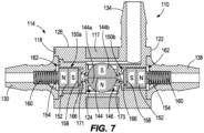
FIG. 7 is a cross-sectional view of the valve ofFIG. 4 with the actuating assembly illustrated in a blocking position. - Before any embodiments of the disclosure are explained in detail, it is to be understood that the disclosure is not limited in its application to the details of construction and the arrangement of components set forth in the following description or illustrated in the following drawings. The disclosure is capable of supporting other embodiments and of being practiced or of being carried out in various ways. Also, it is to be understood that the phraseology and terminology used herein is for the purpose of description and should not be regarded as limiting. The scope of the invention is defined by the claims. In the following description 1 inch corresponds to 2.54 cm.
-
FIGS. 1-3 illustrate avalve 10 according to one embodiment of the present disclosure. The illustratedvalve 10 includes a generallycylindrical housing 14 with afirst end wall 18, asecond end wall 22, and aside wall 26 extending between theend walls 18, 22 (FIG. 1 ). A plurality oflegs 15 extends from theside wall 26, which may facilitate mounting thevalve 10 in various ways. In other embodiments, thehousing 14 may have other shapes and mounting configurations. - Referring to
FIGS. 2 and 3 , thewalls cavity 24 within thehousing 14. An electricallyconductive coil 17 is coupled to the side wall 26 (e.g., in a recess formed in the side wall 26), such that thecoil 17 is concentrically aligned with thecavity 24. Thecoil 17 may be made of copper, silver, gold, or any other suitable electrically conductive material. A power source (not shown) is electrically coupled to thecoil 17 so that the power source and thecoil 17 form a circuit in which the power source is able to drive current through thecoil 17. In the illustrated embodiment, the power source is capable of selectively driving current through thecoil 17 in a first (e.g., positive) direction and a second (e.g., negative) direction. In some embodiments, the direction of current flow through thecoil 17 may be selectively varied using a positive to negative converter, by selectively electrically coupling two different power sources to thecoil 17, or by any other suitable means. - The illustrated
valve 10 includes three ports: a first port orpressure port 30, a second port orbladder port 34, and a third port orvent port 38. Thepressure port 30 may be fluidly coupled to a source of pressurized fluid (e.g., an air pump or compressor, not shown). Thebladder port 34 may be fluidly coupled to a vessel for containing pressurized fluid (e.g., an inflatable bladder; not shown) or to a downstream valve assembly or fluidic switching module configured to route the pressurized air to one or more such vessels. Thevent port 38 is in fluid communication with the environment surrounding thevalve 10. In the illustrated embodiment, thepressure port 30 extends from thefirst end wall 18, thevent port 38 extends from thesecond end wall 22, and thebladder port 34 extends from theside wall 26. In some embodiments, theports housing 14, or theports housing 14. In some embodiments, theports first port 30 may be the vent port, and thethird port 38 may be the pressure port, etc.). - With continued reference to
FIGS. 2 and 3 , anactuator assembly 46 is contained within thecavity 24 of thehousing 14. The illustratedactuator assembly 46 includes afirst valve element 50a, asecond valve element 50b, and an actuatingelement 44. Each of thevalve elements permanent magnet 52 having afirst end 54 and asecond end 58 opposite thefirst end 54. Thefirst ends 54 of themagnets 52 face away from the actuatingelement 44, and thesecond ends 58 of themagnets 52 face toward the actuatingelement 44 in the illustrated embodiment. Thefirst end 54 has a first magnetic polarity (e.g., north), and thesecond end 58 has a second, opposite magnetic polarity (e.g., south). In the illustrated embodiment, thepermanent magnets 52 are rare earth magnets made of NdFeB or any other suitable magnetic material. Themagnets 52 are nickel plated, axially magnetized, and cylindrical in shape, with a diameter of about 1/10-inch and a thickness of about 1/16-inch. In other embodiments, themagnets 52 may be made with different magnetic materials and formed in different shapes or dimensions. - Each of the
valve elements seal 66 coupled to thefirst end 54 of themagnet 52 and aspacer 42 coupled to thesecond end 58. Theseal 66 of thefirst valve element 50a is configured to selectively engage and seal thepressure port 30. Theseal 66 of thesecond valve element 50b is configured to selectively engage and seal thevent port 38. Thespacers 42 are made of a material with a low coefficient of friction, such as Teflon® or Delrin®, and are positioned between themagnets 52 and theactuating element 44. In the illustrated embodiment, thespacers 42 are about 0.025 inches thick; however, thespacers 42 may have other thicknesses. - With continued reference to
FIGS. 2 and 3 , theactuating element 44 is located in thecavity 24 between the first andsecond valve elements coil 17. In the illustrated embodiment, theactuating element 44 is a spherical permanent magnet (e.g., a rare earth magnet such as NeFeB) that is nickel plated and axially magnetized. Theactuating element 44 has a diameter of 1/8 inch in the illustrated embodiment, but theactuating element 44 may be made from different magnetic materials and formed in different shapes or dimensions in other embodiments. For example, in some embodiments, theactuating element 44 may be shaped as a cylinder. Theactuating element 44 includes a firstmagnetic pole 44a (e.g., a north pole) and a secondmagnetic pole 44b (e.g., a south pole) opposite the firstmagnetic pole 44a. In the illustrated embodiment, the firstmagnetic pole 44a has the same magnetic polarity as the first ends 54 of themagnets 52, and the secondmagnetic pole 44b has the same magnetic polarity as the second ends 58 of themagnets 52. - The
actuating element 44 is rotatable between a first orientation (FIG. 2 ) and a second orientation (FIG. 3 ) in response to the power supply driving current through thecoil 17 in the first direction and the second direction, respectively. In response to rotation of theactuating element 44 between the first orientation and the second orientation, thefirst valve element 50a is movable between a closed position (FIG. 3 ), in which theseal 66 of thefirst valve element 50a engages and seals thepressure port 30, and an open position (FIG. 2 ), in which theseal 66 of thefirst valve element 50a is spaced from thepressure port 30 to allow fluid to flow through thepressure port 30. Likewise, thesecond valve element 50b is movable between a closed position (FIG. 2 ) in which theseal 66 of thesecond valve element 50b engages and seals thevent port 38 and an open position (FIG. 3 ) in which theseal 66 of thesecond valve element 50b is spaced from thevent port 38 to allow fluid to flow through thevent port 38. Thevalve elements actuating element 44. - In operation, to inflate the vessel coupled to the
bladder port 34, the power supply is energized to drive current through thecoil 17 in the first direction, moving theactuating element 44 to the first orientation illustrated inFIG. 2 . In particular, the current traveling through thecoil 17 produces a magnetic field that acts on theactuating element 44 to orient the firstmagnetic pole 44a toward thefirst valve element 50a and the secondmagnetic pole 44b toward thesecond valve element 50b. The attractive magnetic force between thesecond end 58 of themagnet 52 in thefirst valve element 50a and the firstmagnetic pole 44a of theactuating element 44 draws thefirst valve element 50a toward theactuating element 44, unsealing thepressure port 30. In the illustrated embodiment, thefirst valve element 50a is displaced to the open position in which thespacer 42 engages theactuating element 44, and theseal 66 is spaced from thepressure port 30. Simultaneously, the magnetic repulsive force between thesecond end 58 of themagnet 52 in thesecond valve element 50b and the secondmagnetic pole 44b of theactuating element 44 pushes thesecond valve element 50b to its closed position so that theseal 66 engages and seals thevent port 38. - Thus, in the inflating configuration of the
valve 10 illustrated inFIG. 2 , thepressure port 30 is open to thechamber 24 and thebladder port 34, while thevent port 38 is sealed. Pressurized air may enter thecavity 24 through thepressure port 30 and then flow to the vessel through thebladder port 34 to inflate the vessel. - To deflate the vessel, the power supply reverses the direction of current in the
coil 17. By driving current through thecoil 17 in the second, opposite direction, theactuating element 44 rotates to the second orientation illustrated inFIG. 3 . In particular, the current traveling through thecoil 17 produces a magnetic field that acts on theactuating element 44 to orient the firstmagnetic pole 44a toward thesecond valve element 50b and the secondmagnetic pole 44b toward thefirst valve element 50a. The attractive magnetic force between thesecond end 58 of themagnet 52 in thesecond valve element 50b and the firstmagnetic pole 44a of theactuating element 44 draws thesecond valve element 50b toward theactuating element 44, unsealing thevent port 38. In the illustrated embodiment, thesecond valve element 50a is displaced to the open position in which thespacer 42 engages theactuating element 44, and theseal 66 is spaced from thevent port 38. Simultaneously, the magnetic repulsive force between thesecond end 58 of themagnet 52 in thefirst valve element 50a and the secondmagnetic pole 44b of theactuating element 44 pushes thefirst valve element 50a to its closed position so that theseal 66 engages and seals thepressure port 30. - Thus, in the deflating configuration of the
valve 10 illustrated inFIG. 3 , thevent port 38 is open to thechamber 24 and thebladder port 34, while thepressure port 30 is sealed. Pressurized air contained within the vessel may enter thecavity 24 through thebladder port 34 and then be vented to the surrounding atmosphere through thevent port 38. - Because the illustrated
actuating element 44 rotates to actuate thevalve 10 between the inflating configuration (FIG. 2 ) and the deflating configuration (FIG. 3 ), a smaller force is required to separate themagnetic poles respective magnets 52. Specifically, as theactuating element 44 rotates, theactuating element 44 and themagnets 52 separate in a shearing motion, which requires less force (e.g., only about 25% of the force in some embodiments) than separating magnets axially (i.e. pulling magnets apart in a direction opposite the magnetic attraction force). Because theactuating element 44 is more easily disengaged from thevalve elements coil 17 to reorient theactuating element 44. Additionally, in the illustrated embodiment, the low-friction spacers 42 allow theactuating element 44 to easily rotate, even when one of thevalve elements actuating element 44. The thickness of eachspacer 42 is selected to provide a desired amount of magnetic force developed between the actuatingelement 44 and themagnets 52. - The illustrated
valve 10 has the advantage that theactuating element 44 drives the displacement of thevalve elements actuator assembly 46 to bias thevalve elements valve 10 can be made more compact than typical valves and may require less maintenance. -
FIGS. 4-7 illustrate avalve 110 according to another embodiment. Thevalve 110 is similar in some aspects to thevalve 10 described above with reference toFIGS. 1-3 . Accordingly, features and elements of thevalve 110 corresponding with features and elements of thevalve 10 are given corresponding reference numbers, plus 100. - The
valve 110 includes ahousing 114. Thehousing 114 is generally cylindrical and has afirst end wall 118, asecond end wall 122, and aside wall 126 extending between theend walls 118, 122 (FIG. 4 ). A plurality oflegs 115 extends from theside wall 126, which may facilitate mounting thevalve 110 in various ways. In other embodiments, thehousing 114 may have other shapes and mounting configurations. - Referring to
FIGS. 5-7 , thewalls cavity 124 within thehousing 114. An electricallyconductive coil 117 is coupled to the side wall 126 (e.g., in a recess formed in the side wall 126), such that thecoil 117 is concentrically aligned with thecavity 124. A power source (not shown) is electrically coupled to thecoil 117 so that the power source and thecoil 117 form a circuit in which the power source is able to drive current through thecoil 117. In the illustrated embodiment, the power source is capable of selectively driving current through thecoil 117 in a first (e.g., positive) direction and a second (e.g., negative) direction. In some embodiments, the direction of current flow through thecoil 117 may be selectively varied using a positive to negative converter, by selectively electrically coupling two different power sources to thecoil 117, or by any other suitable means. In some embodiments, the power source may include a pulse-width modulation (PWM) controller able to selectively vary a duty cycle of current driven in the first direction to current driven in the second direction at high frequency. - The illustrated
valve 110 includes three ports: a first port orpressure port 130, a second port orbladder port 134, and a third port or ventport 138. In the illustrated embodiment, thepressure port 130 extends from thefirst end wall 118, thevent port 138 extends from thesecond end wall 122, and thebladder port 134 extends from theside wall 126. In some embodiments, theports housing 114, or theports housing 114. In some embodiments, theports first port 130 may be the vent port, and thethird port 138 may be the pressure port, etc.). - With reference to
FIGS. 5-7 , anactuator assembly 146 is contained within thecavity 124 of thehousing 114. Theactuator assembly 146 includes afirst valve element 150a, asecond valve element 150b, and anactuating element 144. In the illustrated embodiment, thepressure port 130 and thevent port 138 each include achamber 162 extending into thecavity 124. Thechamber 162 of thepressure port 130 includes an interiorpressure port opening 171, and thechamber 162 of thevent port 138 includes an interiorvent port opening 173. - The
first valve element 150a is disposed within thechamber 162 of thepressure port 130, and thesecond valve element 150b is disposed within thechamber 162 of thevent port 138. Each of thevalve elements permanent magnet 152 having afirst end 154 and asecond end 158 opposite thefirst end 154. The first ends 154 of themagnets 152 face away from theactuating element 144, and the second ends 158 of themagnets 152 face toward theactuating element 144. Thefirst end 154 has a first magnetic polarity (e.g. north), and asecond end 158 has a second, opposite magnetic polarity (e.g. south). In the illustrated embodiment, thepermanent magnets 152 are rare earth magnets made of NdFeB or any other suitable magnetic material. Themagnets 152 are nickel plated, axially magnetized, and cylindrical in shape, with a diameter of about 1/8-inch and a thickness of about 1/8-inch. In other embodiments, themagnets 152 may be made with different magnetic materials and formed in different shapes or dimensions. - Each of the
valve elements seal 166 coupled to thesecond end 158 of themagnet 152. Biasingelements 160, which are coil springs in the illustrated embodiment, engage the first ends 154 of themagnets 152 to bias thevalve elements actuating element 144. In the illustrated embodiment, the biasingelements 160 are accommodated within thepressure port 130 and thevent port 138, respectively. - With continued reference to
FIGS. 5-7 , theactuating element 144 is located within thecavity 124 between thechambers 162 and is surrounded by thecoil 117. In the illustrated embodiment, theactuating element 144 is a spherical permanent magnet (e.g., a rare earth magnet such as NeFeB) that is nickel plated and axially magnetized. Theactuating element 144 has a diameter of 3/16 inch in the illustrated embodiment, but theactuating element 144 may be made from different magnetic materials and formed in different shapes or dimensions in other embodiments. For example, in some embodiments, theactuating element 144 may be shaped as a cylinder. Theactuating element 144 includes a firstmagnetic pole 144a (e.g., a north pole) and a secondmagnetic pole 144b (e.g., a south pole) opposite the firstmagnetic pole 144a. In the illustrated embodiment, the firstmagnetic pole 144a has the same magnetic polarity as the first ends 154 of themagnets 152, and the secondmagnetic pole 144b has the same magnetic polarity as the second ends 158 of themagnets 152. - The
actuating element 144 is rotatable between a first orientation (FIG. 5 ) and a second orientation (FIG. 6 ) in response to the power supply driving current through thecoil 117 in the first direction and the second direction, respectively. In the illustrated embodiment, theactuating element 144 is also rotatable to a third orientation (FIG. 7 ) between the first orientation and the second orientation in response to the power supply switching between driving current in the first direction and the second direction at a high frequency (e.g., via PWM control). - The
first valve element 150a is movable between a closed position (FIGS. 6 and7 ), in which theseal 166 of thefirst valve element 150a engages and seals thepressure port opening 171, and an open position (FIG. 5 ) in which theseal 166 of thefirst valve element 150a is spaced from thepressure port opening 171 to allow fluid to flow through thepressure port 130. Likewise, thesecond valve element 150b is moveable between a closed position (FIGS. 5 and7 ) in which theseal 166 of thesecond valve element 150b engages and seals thevent port opening 173 and an open position (FIG. 6 ) in which theseal 166 of thesecond valve element 150b is spaced from thevent port opening 173 to allow fluid to flow through thevent port 138. Thevalve elements actuating element 144, and under the influence of the biasingelements 160. - In operation, to inflate the vessel coupled to the
bladder port 134, the power supply is energized to drive current through thecoil 117 in the first direction, moving theactuating element 144 to the first orientation illustrated inFIG. 5 . In particular, the current traveling through thecoil 117 produces a magnetic field that acts on theactuating element 144 to orient the secondmagnetic pole 144b toward thefirst valve element 150a and the firstmagnetic pole 144a toward thesecond valve element 150b. The magnetic repulsive force between thesecond end 158 of themagnet 152 of thefirst valve element 150a and the secondmagnetic pole 144b of theactuating element 144 pushes thefirst valve element 150a to its open position against the force of the biasingelement 160. In its open position, theseal 166 of thefirst valve element 150a is spaced from thepressure port opening 171. Simultaneously, the attractive magnetic force between thesecond end 158 of themagnet 152 of thesecond valve element 150b and the firstmagnetic pole 144a of theactuating element 144 combines with the force of the biasingelement 160 to hold thesecond valve element 150b in its closed position with theseal 166 engaged against thevent port opening 173. - Thus, in the inflating configuration of the
valve 110 illustrated inFIG. 5 , thepressure port 130 is open to thechamber 124 and thebladder port 134, while thevent port 138 is sealed at thevent port opening 173. Pressurized air may enter thecavity 124 through thepressure port 130 and then flow to the vessel through thebladder port 134 to inflate the vessel. - To deflate the vessel, the power supply reverses the direction of current in the
coil 117. By driving current through thecoil 117 in the second, opposite direction, theactuating element 144 rotates to the second orientation illustrated inFIG. 6 . In particular, the current traveling through thecoil 117 produces a magnetic field that acts on theactuating element 144 to orient the secondmagnetic pole 144b toward thesecond valve element 150b and the firstmagnetic pole 144a toward thefirst valve element 150a. The magnetic repulsive force between thesecond end 158 of themagnet 152 of thesecond valve element 150b and the secondmagnetic pole 144b of theactuating element 144 pushes thesecond valve element 150b to its open position against the force of the biasingelement 160. In its open position, theseal 166 of thesecond valve element 150b is spaced from thevent port opening 173. Simultaneously, the attractive magnetic force between thesecond end 158 of themagnet 152 of thefirst valve element 150a and the firstmagnetic pole 144a combines with the force of the biasingelement 160 to hold thefirst valve element 150a in its closed position with theseal 166 engaged against thepressure port opening 171. - Thus, in the deflating configuration of the
valve 110 illustrated inFIG. 6 , thevent port 138 is open to thechamber 124 and thebladder port 134, while thepressure port 130 is sealed at thepressure port opening 171. Pressurized air contained within the vessel may enter thecavity 124 through thebladder port 134 and then be vented to the surrounding atmosphere through thevent port 138. - In some embodiments, the
valve 110 may also be actuated to a closed or neutral configuration illustrated inFIG. 7 . As such, thevalve 110 may be configured as a three port-three position valve (i.e. 3/3 valve) instead of a three port-two position valve (i.e. a 3/2 valve) like thevalve 10 described above with reference toFIGS. 1-3 . In such embodiments, theactuating element 144 is rotatable to the third orientation, illustrated inFIG. 7 , in response to the power supply switching between driving current in the first direction and the second direction at a high frequency (e.g., via PWM control). In the illustrated embodiment, the third orientation is midway between the first orientation and the second orientation. - When the
valve 110 is in the neutral configuration, the first andsecond poles actuating element 144 are oriented along a line transverse to a line passing through themagnets 152. As such, theactuating element 144 does not exert a repulsive magnetic force on either of thevalve element elements 160. Thus, both of thevalve element pressure port opening 171 and thevent port opening 173. In the neutral configuration, the source of pressurized fluid (not shown) does not have to continuously provide pressurized air through thepressure port 130 to the vessel coupled to thebladder port 134 to keep the vessel pressurized. - In some embodiments, the
valves valves valves - Although the disclosure has been described in detail with reference to certain preferred embodiments, variations and modifications exist as long as they fall within the scope of the claims.
Claims (14)
- A pneumatic valve (10) comprising:a housing (14) including a first port (30), a second port (34), and a third port (38), wherein each of the first port (30), second port (34) and third port (38) is in fluid communication with a chamber (24) located within the housing (14);a first valve element (50a) located within the chamber (24) and including a first magnet (52), wherein the first valve element (50a) is movable between an open position and a closed position, and the first valve element (50a) is configured to seal the first port (30) in the closed position;a second valve element (50b) located within the chamber (24) and including a second magnet (52), wherein the second valve element (50b) is movable between an open position and a closed position, and the second valve element (50b) is configured to seal the third port (38) in the closed position; anda magnetic actuating element (44) located within the chamber (24) between the first valve element (50a) and the second valve element (50b) and rotatable between a first position and a second position,wherein the first valve element (50a) and the second valve element (50b) are movable between the open position and the closed position in response to rotation of the magnetic actuating element (44) between the first position and the second position,wherein the magnetic actuating element (44) is configured to attract the first valve element (50a) toward the open position and to repel the second valve element (50b) toward the closed position in the first position of the magnetic actuating element (44), andthe magnetic actuating element (44) is configured to repel the first valve element (50a) toward the closed position and to attract the second valve element (50b) toward the open position in the second position of the magnetic actuating element (44) such that when the first valve element (50a) is in the open position, the second valve element (50b) is maintained in the closed position, and, when the second valve element (50b) is in the open position, the first valve element (50a) is maintained in the closed position.
- The pneumatic valve (10) of claim 1, further comprising a coil (17) coupled to the housing (14), wherein the magnetic actuating element (44) is configured to rotate to the first position in response to current being driven through the coil (17) in a first direction, and wherein the magnetic actuating element (44) is configured to rotate to the second position in response to current being driven through the coil (17) in a second direction opposite the first direction.
- The pneumatic valve (10) of any one of the preceding claims, wherein the magnetic actuating element (44) is spherical or cylindrical.
- The pneumatic valve (10) of any one of the preceding claims, wherein the first position is offset 180 degrees from the second position.
- The pneumatic valve (10) of any one of the preceding claims, wherein the first valve element (50a) includes a spacer (42) positioned between the first magnet (52) and the magnetic actuating element (44) and the second valve element (50b) includes a spacer (42) positioned between the second magnet (52) and the magnetic actuating element (44).
- The pneumatic valve (10) of any of the preceding claims, wherein a first end (54) of each of the first and second magnets (52) faces away from the actuating element (44) and has a first magnetic polarity and a second end (58) of each of the first and second magnets (52) faces toward the actuating element (44) and has a second magnetic polarity opposite the first magnetic polarity.
- The pneumatic valve (10) of claim 6, wherein the first magnetic polarity is north and the second magnetic polarity is south.
- The pneumatic valve (10) of claim 6 or 7, wherein a first magnetic pole of the actuating element (44) has the same magnetic polarity as the first end of each of the first and second magnets (52) and a second magnetic pole of the actuating element (44) has the same magnetic polarity as the second end of each of the first and second magnets (52).
- The pneumatic valve (10) of any of the preceding claims, wherein the first port (30) and the third port (38) are coaxial.
- The pneumatic valve (10) of any of the preceding claims, wherein the first port (30) extends from a first end wall (18) of the housing (14) and the third port (38) extends from a second end wall (22) of the housing (14).
- The pneumatic valve (10) of any of the preceding claims, wherein the second port (34) extends from a side wall (26) of the housing (14).
- The pneumatic valve (10) of any of the preceding claims, wherein the first port (30) is a pressure port fluidly coupled to a source of pressurized fluid and the third port (38) is a vent port that is in fluid communication with an environment surrounding the housing (14).
- The pneumatic valve (10) of any of the preceding claims, wherein the second port (34) is configured to be fluidly coupled to a vessel for containing pressurized fluid.
- The pneumatic valve (10) of any of the preceding claims, wherein the actuating element (44) is configured such that as the actuating element (44) rotates between the first position and the second position, the actuating element (44) separates from the first and second magnets (52) in a shearing motion.
Applications Claiming Priority (2)
| Application Number | Priority Date | Filing Date | Title |
|---|---|---|---|
| US201962868201P | 2019-06-28 | 2019-06-28 | |
| PCT/CA2020/000077 WO2020257912A1 (en) | 2019-06-28 | 2020-06-26 | Magnetic valve |
Publications (3)
| Publication Number | Publication Date |
|---|---|
| EP3990812A1 EP3990812A1 (en) | 2022-05-04 |
| EP3990812A4 EP3990812A4 (en) | 2023-07-19 |
| EP3990812B1 true EP3990812B1 (en) | 2025-02-26 |
Family
ID=74061132
Family Applications (1)
| Application Number | Title | Priority Date | Filing Date |
|---|---|---|---|
| EP20832916.9A Active EP3990812B1 (en) | 2019-06-28 | 2020-06-26 | Magnetic valve |
Country Status (2)
| Country | Link |
|---|---|
| EP (1) | EP3990812B1 (en) |
| WO (1) | WO2020257912A1 (en) |
Family Cites Families (10)
| Publication number | Priority date | Publication date | Assignee | Title |
|---|---|---|---|---|
| US3203447A (en) * | 1963-10-09 | 1965-08-31 | Skinner Prec Ind Inc | Magnetically operated valve |
| US4630799A (en) * | 1983-09-14 | 1986-12-23 | Nolan John H | Remotely controlled override valve with calibration means |
| GB8806272D0 (en) * | 1988-03-16 | 1988-04-13 | Eaton Sa Monaco | Two position valve |
| DE4117958C2 (en) * | 1991-05-31 | 2000-05-11 | Bosch Gmbh Robert | magnetic valve |
| CN2526615Y (en) * | 2002-02-09 | 2002-12-18 | 吕宇峰 | Internal rotation opening-closing type non-leakage permanent magnet driven valve |
| EP1350757A1 (en) * | 2002-03-27 | 2003-10-08 | JohnsonDiversey, Inc. | Flow restriction device |
| GB2401926B (en) * | 2003-05-23 | 2005-12-14 | Camcon Ltd | Electromagnetic actuator and integrated actuator and fluid flow control valve |
| CN101922578B (en) * | 2010-09-06 | 2011-11-23 | 周智宇 | Water backflow preventing valve and water backflow preventing and gas leakage preventing automatic self-closing gas valve |
| DE102012011975B4 (en) * | 2012-06-15 | 2018-09-20 | Rolf Prettl | Valve arrangement and tank module for a urea injection system |
| US9797521B1 (en) * | 2016-08-09 | 2017-10-24 | Edward P Davis | Rotary magnetic coupling actuated valve with external magnets and internal magnetic flux path |
-
2020
- 2020-06-26 WO PCT/CA2020/000077 patent/WO2020257912A1/en not_active Ceased
- 2020-06-26 EP EP20832916.9A patent/EP3990812B1/en active Active
Also Published As
| Publication number | Publication date |
|---|---|
| EP3990812A1 (en) | 2022-05-04 |
| EP3990812A4 (en) | 2023-07-19 |
| WO2020257912A1 (en) | 2020-12-30 |
Similar Documents
| Publication | Publication Date | Title |
|---|---|---|
| US20120175974A1 (en) | Compact electromechanical mechanism and devices incorporating the same | |
| US8567440B2 (en) | Solenoid operated valve | |
| US20130328649A1 (en) | Divergent flux path magnetic actuator and devices incorporating the same | |
| CN114110205B (en) | Bistable electromagnetic three-way valve | |
| US20250146594A1 (en) | Latching valve | |
| AU2004311612A1 (en) | Pneumatically actuated valve | |
| US20140107589A1 (en) | Electromagnetically actuated valve and related methods of use | |
| US5734310A (en) | Magnetic latching solenoid assembly | |
| KR20190045866A (en) | Latching pneumatic control valve | |
| EP0349723A1 (en) | Electropneumatic rotary actuator having proportional fluid valving | |
| US7481415B2 (en) | Multi-force actuator valve with multiple operating modes | |
| US20100006788A1 (en) | Valve assembly having magnetically-energized seal mechanism | |
| CN218177993U (en) | Cam type electric valve | |
| CN110486525A (en) | A kind of permanent magnet electromagnetic valve | |
| US6328279B1 (en) | Miniature electrically operated diaphragm valve | |
| EP3990812A1 (en) | Magnetic valve | |
| US11098824B2 (en) | Fluidic valve device | |
| EP3545221B1 (en) | Ultra-low carryover solenoid valve | |
| CN110748690A (en) | Valve with energy-saving electric actuator | |
| WO2006125259A1 (en) | Magnetically actuated valve | |
| JP5033317B2 (en) | Valve mechanism | |
| CN114278763A (en) | Multi-state bistable electromagnetic three-way micro valve based on flexible magnet | |
| WO2022173060A1 (en) | Pump | |
| JP2002106746A (en) | Three-way valve device | |
| EP2875241A1 (en) | Pulse controlled linear actuator |
Legal Events
| Date | Code | Title | Description |
|---|---|---|---|
| STAA | Information on the status of an ep patent application or granted ep patent |
Free format text: STATUS: THE INTERNATIONAL PUBLICATION HAS BEEN MADE |
|
| PUAI | Public reference made under article 153(3) epc to a published international application that has entered the european phase |
Free format text: ORIGINAL CODE: 0009012 |
|
| STAA | Information on the status of an ep patent application or granted ep patent |
Free format text: STATUS: REQUEST FOR EXAMINATION WAS MADE |
|
| 17P | Request for examination filed |
Effective date: 20220118 |
|
| AK | Designated contracting states |
Kind code of ref document: A1 Designated state(s): AL AT BE BG CH CY CZ DE DK EE ES FI FR GB GR HR HU IE IS IT LI LT LU LV MC MK MT NL NO PL PT RO RS SE SI SK SM TR |
|
| DAV | Request for validation of the european patent (deleted) | ||
| DAX | Request for extension of the european patent (deleted) | ||
| P01 | Opt-out of the competence of the unified patent court (upc) registered |
Effective date: 20230523 |
|
| A4 | Supplementary search report drawn up and despatched |
Effective date: 20230619 |
|
| RIC1 | Information provided on ipc code assigned before grant |
Ipc: F16K 1/14 20060101ALI20230613BHEP Ipc: F16K 31/08 20060101AFI20230613BHEP |
|
| STAA | Information on the status of an ep patent application or granted ep patent |
Free format text: STATUS: EXAMINATION IS IN PROGRESS |
|
| 17Q | First examination report despatched |
Effective date: 20240318 |
|
| GRAP | Despatch of communication of intention to grant a patent |
Free format text: ORIGINAL CODE: EPIDOSNIGR1 |
|
| STAA | Information on the status of an ep patent application or granted ep patent |
Free format text: STATUS: GRANT OF PATENT IS INTENDED |
|
| INTG | Intention to grant announced |
Effective date: 20240920 |
|
| GRAS | Grant fee paid |
Free format text: ORIGINAL CODE: EPIDOSNIGR3 |
|
| GRAA | (expected) grant |
Free format text: ORIGINAL CODE: 0009210 |
|
| STAA | Information on the status of an ep patent application or granted ep patent |
Free format text: STATUS: THE PATENT HAS BEEN GRANTED |
|
| AK | Designated contracting states |
Kind code of ref document: B1 Designated state(s): AL AT BE BG CH CY CZ DE DK EE ES FI FR GB GR HR HU IE IS IT LI LT LU LV MC MK MT NL NO PL PT RO RS SE SI SK SM TR |
|
| REG | Reference to a national code |
Ref country code: GB Ref legal event code: FG4D |
|
| REG | Reference to a national code |
Ref country code: CH Ref legal event code: EP |
|
| REG | Reference to a national code |
Ref country code: DE Ref legal event code: R096 Ref document number: 602020046908 Country of ref document: DE |
|
| REG | Reference to a national code |
Ref country code: IE Ref legal event code: FG4D |
|
| REG | Reference to a national code |
Ref country code: NL Ref legal event code: MP Effective date: 20250226 |
|
| PG25 | Lapsed in a contracting state [announced via postgrant information from national office to epo] |
Ref country code: RS Free format text: LAPSE BECAUSE OF FAILURE TO SUBMIT A TRANSLATION OF THE DESCRIPTION OR TO PAY THE FEE WITHIN THE PRESCRIBED TIME-LIMIT Effective date: 20250526 |
|
| PG25 | Lapsed in a contracting state [announced via postgrant information from national office to epo] |
Ref country code: FI Free format text: LAPSE BECAUSE OF FAILURE TO SUBMIT A TRANSLATION OF THE DESCRIPTION OR TO PAY THE FEE WITHIN THE PRESCRIBED TIME-LIMIT Effective date: 20250226 |
|
| PG25 | Lapsed in a contracting state [announced via postgrant information from national office to epo] |
Ref country code: PL Free format text: LAPSE BECAUSE OF FAILURE TO SUBMIT A TRANSLATION OF THE DESCRIPTION OR TO PAY THE FEE WITHIN THE PRESCRIBED TIME-LIMIT Effective date: 20250226 |
|
| PGFP | Annual fee paid to national office [announced via postgrant information from national office to epo] |
Ref country code: DE Payment date: 20250402 Year of fee payment: 6 |
|
| PG25 | Lapsed in a contracting state [announced via postgrant information from national office to epo] |
Ref country code: ES Free format text: LAPSE BECAUSE OF FAILURE TO SUBMIT A TRANSLATION OF THE DESCRIPTION OR TO PAY THE FEE WITHIN THE PRESCRIBED TIME-LIMIT Effective date: 20250226 |
|
| PGFP | Annual fee paid to national office [announced via postgrant information from national office to epo] |
Ref country code: GB Payment date: 20250401 Year of fee payment: 6 |
|
| REG | Reference to a national code |
Ref country code: LT Ref legal event code: MG9D |
|
| PG25 | Lapsed in a contracting state [announced via postgrant information from national office to epo] |
Ref country code: NO Free format text: LAPSE BECAUSE OF FAILURE TO SUBMIT A TRANSLATION OF THE DESCRIPTION OR TO PAY THE FEE WITHIN THE PRESCRIBED TIME-LIMIT Effective date: 20250526 Ref country code: IS Free format text: LAPSE BECAUSE OF FAILURE TO SUBMIT A TRANSLATION OF THE DESCRIPTION OR TO PAY THE FEE WITHIN THE PRESCRIBED TIME-LIMIT Effective date: 20250626 |
|
| PG25 | Lapsed in a contracting state [announced via postgrant information from national office to epo] |
Ref country code: NL Free format text: LAPSE BECAUSE OF FAILURE TO SUBMIT A TRANSLATION OF THE DESCRIPTION OR TO PAY THE FEE WITHIN THE PRESCRIBED TIME-LIMIT Effective date: 20250226 |
|
| PG25 | Lapsed in a contracting state [announced via postgrant information from national office to epo] |
Ref country code: HR Free format text: LAPSE BECAUSE OF FAILURE TO SUBMIT A TRANSLATION OF THE DESCRIPTION OR TO PAY THE FEE WITHIN THE PRESCRIBED TIME-LIMIT Effective date: 20250226 |
|
| PG25 | Lapsed in a contracting state [announced via postgrant information from national office to epo] |
Ref country code: PT Free format text: LAPSE BECAUSE OF FAILURE TO SUBMIT A TRANSLATION OF THE DESCRIPTION OR TO PAY THE FEE WITHIN THE PRESCRIBED TIME-LIMIT Effective date: 20250626 Ref country code: LV Free format text: LAPSE BECAUSE OF FAILURE TO SUBMIT A TRANSLATION OF THE DESCRIPTION OR TO PAY THE FEE WITHIN THE PRESCRIBED TIME-LIMIT Effective date: 20250226 |
|
| PGFP | Annual fee paid to national office [announced via postgrant information from national office to epo] |
Ref country code: FR Payment date: 20250508 Year of fee payment: 6 |
|
| PG25 | Lapsed in a contracting state [announced via postgrant information from national office to epo] |
Ref country code: GR Free format text: LAPSE BECAUSE OF FAILURE TO SUBMIT A TRANSLATION OF THE DESCRIPTION OR TO PAY THE FEE WITHIN THE PRESCRIBED TIME-LIMIT Effective date: 20250527 Ref country code: BG Free format text: LAPSE BECAUSE OF FAILURE TO SUBMIT A TRANSLATION OF THE DESCRIPTION OR TO PAY THE FEE WITHIN THE PRESCRIBED TIME-LIMIT Effective date: 20250226 |
|
| REG | Reference to a national code |
Ref country code: AT Ref legal event code: MK05 Ref document number: 1770919 Country of ref document: AT Kind code of ref document: T Effective date: 20250226 |
|
| PG25 | Lapsed in a contracting state [announced via postgrant information from national office to epo] |
Ref country code: SE Free format text: LAPSE BECAUSE OF FAILURE TO SUBMIT A TRANSLATION OF THE DESCRIPTION OR TO PAY THE FEE WITHIN THE PRESCRIBED TIME-LIMIT Effective date: 20250226 |
|
| PG25 | Lapsed in a contracting state [announced via postgrant information from national office to epo] |
Ref country code: SM Free format text: LAPSE BECAUSE OF FAILURE TO SUBMIT A TRANSLATION OF THE DESCRIPTION OR TO PAY THE FEE WITHIN THE PRESCRIBED TIME-LIMIT Effective date: 20250226 |
|
| PG25 | Lapsed in a contracting state [announced via postgrant information from national office to epo] |
Ref country code: DK Free format text: LAPSE BECAUSE OF FAILURE TO SUBMIT A TRANSLATION OF THE DESCRIPTION OR TO PAY THE FEE WITHIN THE PRESCRIBED TIME-LIMIT Effective date: 20250226 |
|
| PG25 | Lapsed in a contracting state [announced via postgrant information from national office to epo] |
Ref country code: IT Free format text: LAPSE BECAUSE OF FAILURE TO SUBMIT A TRANSLATION OF THE DESCRIPTION OR TO PAY THE FEE WITHIN THE PRESCRIBED TIME-LIMIT Effective date: 20250226 |
|
| PG25 | Lapsed in a contracting state [announced via postgrant information from national office to epo] |
Ref country code: AT Free format text: LAPSE BECAUSE OF FAILURE TO SUBMIT A TRANSLATION OF THE DESCRIPTION OR TO PAY THE FEE WITHIN THE PRESCRIBED TIME-LIMIT Effective date: 20250226 |
|
| PG25 | Lapsed in a contracting state [announced via postgrant information from national office to epo] |
Ref country code: CZ Free format text: LAPSE BECAUSE OF FAILURE TO SUBMIT A TRANSLATION OF THE DESCRIPTION OR TO PAY THE FEE WITHIN THE PRESCRIBED TIME-LIMIT Effective date: 20250226 Ref country code: EE Free format text: LAPSE BECAUSE OF FAILURE TO SUBMIT A TRANSLATION OF THE DESCRIPTION OR TO PAY THE FEE WITHIN THE PRESCRIBED TIME-LIMIT Effective date: 20250226 |
|
| PG25 | Lapsed in a contracting state [announced via postgrant information from national office to epo] |
Ref country code: RO Free format text: LAPSE BECAUSE OF FAILURE TO SUBMIT A TRANSLATION OF THE DESCRIPTION OR TO PAY THE FEE WITHIN THE PRESCRIBED TIME-LIMIT Effective date: 20250226 |
|
| PG25 | Lapsed in a contracting state [announced via postgrant information from national office to epo] |
Ref country code: SK Free format text: LAPSE BECAUSE OF FAILURE TO SUBMIT A TRANSLATION OF THE DESCRIPTION OR TO PAY THE FEE WITHIN THE PRESCRIBED TIME-LIMIT Effective date: 20250226 |
|
| REG | Reference to a national code |
Ref country code: DE Ref legal event code: R097 Ref document number: 602020046908 Country of ref document: DE |
|
| PLBE | No opposition filed within time limit |
Free format text: ORIGINAL CODE: 0009261 |
|
| STAA | Information on the status of an ep patent application or granted ep patent |
Free format text: STATUS: NO OPPOSITION FILED WITHIN TIME LIMIT |
|
| REG | Reference to a national code |
Ref country code: CH Ref legal event code: L10 Free format text: ST27 STATUS EVENT CODE: U-0-0-L10-L00 (AS PROVIDED BY THE NATIONAL OFFICE) Effective date: 20260107 |
|
| REG | Reference to a national code |
Ref country code: CH Ref legal event code: H13 Free format text: ST27 STATUS EVENT CODE: U-0-0-H10-H13 (AS PROVIDED BY THE NATIONAL OFFICE) Effective date: 20260127 |
|
| PG25 | Lapsed in a contracting state [announced via postgrant information from national office to epo] |
Ref country code: MC Free format text: LAPSE BECAUSE OF FAILURE TO SUBMIT A TRANSLATION OF THE DESCRIPTION OR TO PAY THE FEE WITHIN THE PRESCRIBED TIME-LIMIT Effective date: 20250226 |
|
| 26N | No opposition filed |
Effective date: 20251127 |
|
| PG25 | Lapsed in a contracting state [announced via postgrant information from national office to epo] |
Ref country code: LU Free format text: LAPSE BECAUSE OF NON-PAYMENT OF DUE FEES Effective date: 20250626 |
|
| REG | Reference to a national code |
Ref country code: BE Ref legal event code: MM Effective date: 20250630 |
|
| PG25 | Lapsed in a contracting state [announced via postgrant information from national office to epo] |
Ref country code: IE Free format text: LAPSE BECAUSE OF NON-PAYMENT OF DUE FEES Effective date: 20250626 |
|
| PG25 | Lapsed in a contracting state [announced via postgrant information from national office to epo] |
Ref country code: BE Free format text: LAPSE BECAUSE OF NON-PAYMENT OF DUE FEES Effective date: 20250630 |
|
| PG25 | Lapsed in a contracting state [announced via postgrant information from national office to epo] |
Ref country code: CH Free format text: LAPSE BECAUSE OF NON-PAYMENT OF DUE FEES Effective date: 20250630 |