EP3990785B1 - Scroll compressor - Google Patents
Scroll compressor Download PDFInfo
- Publication number
- EP3990785B1 EP3990785B1 EP20847631.7A EP20847631A EP3990785B1 EP 3990785 B1 EP3990785 B1 EP 3990785B1 EP 20847631 A EP20847631 A EP 20847631A EP 3990785 B1 EP3990785 B1 EP 3990785B1
- Authority
- EP
- European Patent Office
- Prior art keywords
- circular arc
- arc portion
- connection
- center
- scroll
- Prior art date
- Legal status (The legal status is an assumption and is not a legal conclusion. Google has not performed a legal analysis and makes no representation as to the accuracy of the status listed.)
- Active
Links
Images




Classifications
-
- F—MECHANICAL ENGINEERING; LIGHTING; HEATING; WEAPONS; BLASTING
- F04—POSITIVE - DISPLACEMENT MACHINES FOR LIQUIDS; PUMPS FOR LIQUIDS OR ELASTIC FLUIDS
- F04C—ROTARY-PISTON, OR OSCILLATING-PISTON, POSITIVE-DISPLACEMENT MACHINES FOR LIQUIDS; ROTARY-PISTON, OR OSCILLATING-PISTON, POSITIVE-DISPLACEMENT PUMPS
- F04C18/00—Rotary-piston pumps specially adapted for elastic fluids
- F04C18/02—Rotary-piston pumps specially adapted for elastic fluids of arcuate-engagement type, i.e. with circular translatory movement of co-operating members, each member having the same number of teeth or tooth-equivalents
- F04C18/0207—Rotary-piston pumps specially adapted for elastic fluids of arcuate-engagement type, i.e. with circular translatory movement of co-operating members, each member having the same number of teeth or tooth-equivalents both members having co-operating elements in spiral form
- F04C18/0215—Rotary-piston pumps specially adapted for elastic fluids of arcuate-engagement type, i.e. with circular translatory movement of co-operating members, each member having the same number of teeth or tooth-equivalents both members having co-operating elements in spiral form where only one member is moving
-
- F—MECHANICAL ENGINEERING; LIGHTING; HEATING; WEAPONS; BLASTING
- F04—POSITIVE - DISPLACEMENT MACHINES FOR LIQUIDS; PUMPS FOR LIQUIDS OR ELASTIC FLUIDS
- F04C—ROTARY-PISTON, OR OSCILLATING-PISTON, POSITIVE-DISPLACEMENT MACHINES FOR LIQUIDS; ROTARY-PISTON, OR OSCILLATING-PISTON, POSITIVE-DISPLACEMENT PUMPS
- F04C23/00—Combinations of two or more pumps, each being of rotary-piston or oscillating-piston type, specially adapted for elastic fluids; Pumping installations specially adapted for elastic fluids; Multi-stage pumps specially adapted for elastic fluids
- F04C23/008—Hermetic pumps
-
- F—MECHANICAL ENGINEERING; LIGHTING; HEATING; WEAPONS; BLASTING
- F04—POSITIVE - DISPLACEMENT MACHINES FOR LIQUIDS; PUMPS FOR LIQUIDS OR ELASTIC FLUIDS
- F04C—ROTARY-PISTON, OR OSCILLATING-PISTON, POSITIVE-DISPLACEMENT MACHINES FOR LIQUIDS; ROTARY-PISTON, OR OSCILLATING-PISTON, POSITIVE-DISPLACEMENT PUMPS
- F04C18/00—Rotary-piston pumps specially adapted for elastic fluids
- F04C18/02—Rotary-piston pumps specially adapted for elastic fluids of arcuate-engagement type, i.e. with circular translatory movement of co-operating members, each member having the same number of teeth or tooth-equivalents
- F04C18/0207—Rotary-piston pumps specially adapted for elastic fluids of arcuate-engagement type, i.e. with circular translatory movement of co-operating members, each member having the same number of teeth or tooth-equivalents both members having co-operating elements in spiral form
- F04C18/0246—Details concerning the involute wraps or their base, e.g. geometry
- F04C18/0269—Details concerning the involute wraps
-
- F—MECHANICAL ENGINEERING; LIGHTING; HEATING; WEAPONS; BLASTING
- F04—POSITIVE - DISPLACEMENT MACHINES FOR LIQUIDS; PUMPS FOR LIQUIDS OR ELASTIC FLUIDS
- F04C—ROTARY-PISTON, OR OSCILLATING-PISTON, POSITIVE-DISPLACEMENT MACHINES FOR LIQUIDS; ROTARY-PISTON, OR OSCILLATING-PISTON, POSITIVE-DISPLACEMENT PUMPS
- F04C2240/00—Components
- F04C2240/40—Electric motor
-
- F—MECHANICAL ENGINEERING; LIGHTING; HEATING; WEAPONS; BLASTING
- F04—POSITIVE - DISPLACEMENT MACHINES FOR LIQUIDS; PUMPS FOR LIQUIDS OR ELASTIC FLUIDS
- F04C—ROTARY-PISTON, OR OSCILLATING-PISTON, POSITIVE-DISPLACEMENT MACHINES FOR LIQUIDS; ROTARY-PISTON, OR OSCILLATING-PISTON, POSITIVE-DISPLACEMENT PUMPS
- F04C29/00—Component parts, details or accessories of pumps or pumping installations, not provided for in groups F04C18/00 - F04C28/00
- F04C29/0042—Driving elements, brakes, couplings, transmissions specially adapted for pumps
- F04C29/005—Means for transmitting movement from the prime mover to driven parts of the pump, e.g. clutches, couplings, transmissions
- F04C29/0057—Means for transmitting movement from the prime mover to driven parts of the pump, e.g. clutches, couplings, transmissions for eccentric movement
Definitions
- the disclosure relates to a scroll compressor.
- a scroll compressor is a compressor including a fixed scroll having a fixing wrap and an orbiting scroll having an orbiting wrap corresponding to the fixing wrap of the fixed scroll, wherein the orbiting scroll orbits the fixed scroll to form a compression chamber moving continuously between the fixing wrap and the orbiting wrap to inhale and compress a refrigerant.
- the scroll compressor is excellent compared to other types of compressors in view of vibrations and noise that are generated during an operation, because inhalation, compression, and discharge are performed successively.
- an orbiting wrap is formed on one side of a disk-shaped end plate, a boss portion is formed on the other side of the end plate where no orbiting wrap is formed, and a rotation shaft for driving the orbiting scroll is coupled to the boss portion.
- the scroll compressor is capable of reducing the diameter of the end plate because the orbiting wrap is formed over the entire area of the end plate.
- an action point at which a repulsive force of a refrigerant is applied upon compression is spaced from an action point at which a reaction force for cancelling the repulsive force is applied, so that the behavior of the orbiting scroll may become unstable upon an operation, and accordingly, the scroll compressor may cause great vibrations or noise.
- a shaft penetration scroll compressor or a semi shaft penetration scroll compressor in which an action point at which a repulsive force of a refrigerant is applied and an action point for cancelling the repulsive force is applied are at the same location has been disclosed.
- the shaft penetration scroll compressor or the semi shaft penetration scroll compressor prevents an orbiting scroll from being inclined with respect to a rotation shaft, because the action point of the repulsive force of the refrigerant and the action point of the reaction force are at the same location.
- the shaft penetration scroll compressor or the semi shaft penetration scroll compressor may not form an orbiting wrap over the entire area of an end plate because the rotation shaft needs to be inserted in the center portion of the end plate. Therefore, a compression space of a compression chamber is reduced, and furthermore, a design volume ratio of the scroll compressor is reduced.
- a scroll compressor is provided as defined in claim 1.
- An included angle ⁇ of a first line segment connecting one end of the connection portion to a center of the compressing portion and a second line segment connecting the other end of the connection portion to the center of the compressing portion may be 100 ° or more.
- Each of the first circular arc portion and the second circular arc portion may have a constant thickness, and the thickness of the first circular arc portion may be the same as the thickness of the second circular arc portion.
- the compressing portion may further include a shaft coupling portion positioned in an inside of the second circular arc portion and spaced a preset distance from the second circular arc portion, wherein the eccentric portion is coupled to the shaft coupling portion.
- the shaft coupling portion may include a third circular arc portion forming an outer surface of the shaft coupling portion, wherein a curvature of the third circular arc portion is constant.
- a distance between the first circular arc portion and the second circular arc portion may be equal to a distance between the second circular arc portion and the third circular arc portion.
- connection portion may include: a first connection portion connecting the first circular arc portion to the second circular arc portion, and a second connection portion connecting the second circular arc portion to the third circular arc portion, wherein a curvature of the second connection portion changes from the second circular arc portion to the third circular arc portion.
- Each of the first circular arc portion and the second circular arc portion may include an outer surface and an inner surface
- the third circular arc portion may include an outer surface
- the first connection portion may include a first connection surface connecting the outer surface of the first circular arc portion to the outer surface of the second circular arc portion, and a second connection surface connecting the inner surface of the first circular arc portion to the inner surface of the second circular arc portion.
- the second connection portion may include a third connection surface connecting the outer surface of the second circular arc portion to the outer surface of the third circular arc portion.
- a first angle which is an included angle of a line segment connecting one end of the first connection surface to the center of the compressing portion and a line segment connecting the other end of the first connection surface to the center of the compressing portion, a second angle which is an included angle of a line segment connecting one end of the second connection surface to the center of the compressing portion and a line segment connecting the other end of the second connection surface to the center of the compressing portion, and a third angle which is an included angle of a line segment connecting one end of the third connection surface to the center of the compressing portion and a line segment connecting the other end of the third connection surface to the center of the compressing portion may be different from each other.
- the first angle may be 95 °
- the second angle may be 115 °
- the third angle may be 135 °.
- a center of the shaft coupling portion may be out of a center of the compressing portion.
- the curved portion may be in a shape of an involute curve having a center which is off set from a center of the fixed scroll or the orbiting scroll.
- a scroll compressor capable of increasing a design volume ratio by changing a shape of a wrap may be provided.
- a scroll compressor capable of expanding a compression space by changing a shape of a wrap may be provided.
- a shaft penetration scroll compressor or a semi shaft penetration scroll compressor capable of increasing a design volume ratio by including a new shape of a wrap structure may be provided.
- front end In the following description, the terms “front end”, “rear end”, “upper portion”, “lower portion”, “upper end”, and “lower end” are defined based on the drawings, and the shapes and positions of the corresponding components are not limited by the terms.
- the expression "at least one of a, b or c" indicates only a, only b, only c, both a and b, both a and c, both b and c, all of a, b, and c, or variations thereof.
- FIG. 1 is a longitudinal sectional view of a scroll compressor according to an embodiment of the invention.
- a scroll compressor 1 includes a main body 10, a fixed scroll 20 fixed inside the main body 10, an orbiting scroll 100 orbiting the fixed scroll 20, compressing portions 22 and 102 respectively provided in the fixed scroll 20 and the orbiting scroll 100, and a driving motor 30 for driving the orbiting scroll 100.
- the main body 10 includes an upper cap 11 and a lower cap 12 respectively mounted on a top end and a lower end of the main body 10 to seal an inside of the main body 10, a suction pipe 13 which a refrigerant enters, and a discharge pipe 14 for discharging the refrigerant entered the suction pipe 13 to an outside of the main body 10 after the refrigerant is compressed.
- the fixed scroll 20 includes a first end plate 21 being in a shape of a disk, and a fixing wrap 22 extending downward from the first end plate 21 and forming a compression chamber together with an orbiting wrap 102 which will be described later.
- the orbiting scroll 100 includes a second end plate 101 being opposite to the first end plate 21 and being in a shape of a disk, and the orbiting wrap 102 extending upward from the second end plate 101 and forming the compression chamber together with the fixing wrap 22. Also, the orbiting scroll 100 includes a shaft coupling portion 130 in which an eccentric portion 42 of a rotation shaft 40 which will be described later is inserted.
- the compressing portions 22 and 102 includes the orbiting wrap 102 of the orbiting scroll 100 and the fixing wrap 22 of the fixed scroll 20. That is, the compressing portions 22 and 110 may indicate all of the orbiting wrap 102 and the fixing wrap 22.
- the fixing wrap 22 of the fixed scroll 20 are engaged with the orbiting wrap 102 of the orbiting scroll 100 to form a compression chamber 50.
- the compression chamber 50 is formed by the fixed scroll 20 and the orbiting scroll 100, and a volume of the compression chamber 50 is reduced by an orbiting motion of the orbiting scroll 100. Therefore, a refrigerant entered the compression chamber 50 is compressed.
- a refrigerant entered the compression chamber 50 and compressed is discharged as a high-pressure refrigerant, and a refrigerant existing inside the compression chamber 50 presses the orbiting scroll 100 in a direction in which the orbiting scroll 100 is away from the fixed scroll 20.
- a back pressure chamber 18 for transferring pressure in a direction in which the orbiting scroll 100 faces the fixed scroll 20 may be provided below the orbiting scroll 100.
- a refrigerant may be filled in an inside of the back pressure chamber 18.
- the back pressure chamber 18 may be formed by a main frame 15, the rotation shaft 40, and the orbiting scroll 100.
- An Oldham's ring 17 for orbiting the orbiting scroll 100 without revolving the orbiting scroll 100 may be provided between the orbiting scroll 100 and the main frame 15.
- the main frame 15 and a sub frame 16 may be respectively fixed on upper and lower portions of an inner surface of the main body 10, and the driving motor 30 may be positioned between the main frame 15 and the sub frame 16.
- the driving motor 30 may include a stator 31 and a rotor 32.
- the stator 31 may include a stator body 311, and a coil 312 wound around the stator body 311.
- the stator body 311 may be a laminate formed by stacking a plurality of electrical steel sheets, and may be substantially in a shape of a cylinder, wherein a diameter of an outer circumference surface of the stator body 311 may be larger than a diameter of an inner circumference surface of the main body 10, and therefore, the stator body 311 may be fitted in the main body 10 by interference fit.
- the stator body 311 may include a plurality of teeth (not shown) arranged in a circumference direction on the inner portion that is opposite to an outer circumference of the rotor 32.
- the coil 312 may be positioned at a slot (not shown) existing between neighboring teeth.
- the rotor 32 may be a laminate formed by stacking a plurality of electrical steel sheets each being in a shape of a ring. A diameter of an inner circumference surface of the rotor 32 may be smaller than a diameter of an outer circumference surface of the rotation shaft 40.
- the rotation shaft 40 may be fitted in the rotor 32 by interference fit. A method of fitting the rotation shaft 40 in the rotor 32 may be press-fit. Therefore, the rotation shaft 40 may rotate together with the rotor 32.
- the rotation shaft 40 includes a main shaft 41 inserted in the rotor 32, and an eccentric portion 42 positioned at an upper portion of the main shaft 41 and having a shaft center being eccentric from a shaft center of the main shaft 41.
- the rotation shaft 40 may be installed between the main frame 15 and the sub frame 16 to transfer a rotation force generated by the driving motor 30 to the orbiting scroll 100.
- the main frame 15 may include a main bearing 15a for supporting rotations of the rotation shaft 40.
- a lower portion of the rotation shaft 40 may be supported by the sub frame 16 in such a way to be rotatable with respect to the sub frame 16.
- the sub frame 16 may include a sub bearing 16a for supporting rotations of the rotation shaft 40.
- the orbiting scroll 100 may include the shaft coupling portion 130 in which the eccentric portion 42 is inserted.
- the shaft coupling portion 130 may protrude upward from the second end plate 101 of the orbiting scroll 100.
- the eccentric portion 42 may protrude upward from the second end plate 101, and the eccentric portion 42 may be positioned alongside the orbiting wrap 102 and the fixing wrap 22.
- the orbiting scroll 100 may include an orbiting bearing 42a positioned on an inner surface of the shaft coupling portion 130.
- the orbiting bearing 42a may support rotations of the eccentric portion 42.
- the above-described structure of the orbiting scroll 100 is referred to as a semi shaft penetration structure, and hereinafter, a semi shaft penetration scroll compressor will be described as an example.
- the disclosure is not limited to the semi shaft penetration scroll compressor, and may be applied to a shaft penetration scroll compressor.
- a rotation shaft needs to be inserted in a center of an end plate of an orbiting scroll. Therefore, it is difficult to form an orbiting wrap over the entire area of the end plate, and accordingly, a compression space and a design volume ratio may be reduced. According to a concept of the disclosure, a scroll compressor capable of expanding a compression space and increasing a design volume ratio by improving a wrap shape while having a semi shaft penetration structure or a shaft penetration structure is disclosed.
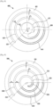
- FIG. 2 is a top view of the orbiting scroll 100 in the scroll compressor 1 according to an embodiment of the disclosure.
- an orbiting wrap shape of the orbiting scroll 100 will be described as an example. Due to characteristics of the scroll compressor 1, because a fixing wrap shape of the fixed scroll 20 corresponds to the orbiting wrap shape, the following descriptions may also be applicable to the fixing wrap 22 of the fixed scroll 20.
- the orbiting scroll 100 may include the second end plate 101, and an orbiting wrap protruding upward from the second end plate 101.
- the orbiting wrap may include a first circular arc portion 110 having a constant curvature, a second circular arc portion 120 positioned in an inside of the first circular arc portion 110 and having a constant curvature, and a connection portion 140 connecting the first circular arc portion 110 to the second circular arc portion 120.
- the first circular arc portion 110 may be in a shape of an arc having a preset radius.
- the second circular arc portion 120 may also be in a shape of a arc, like the first circular arc portion 110, wherein a center of the second circular arc portion 120 may be at the same location as that of the first circular arc portion 110 and the radius of the second circular arc portion 120 may be smaller than that of the first circular arc portion 110.
- the shaft coupling portion 130 may be positioned in an inside of the second circular arc portion 120.
- An outer surface of the shaft coupling portion 130 may form a third circular arc portion 131.
- a center of the third circular arc portion 131 may be at the same location as those of the first circular arc portion 110 and the second circular arc portion 120, and the third circular arc portion 131 may be in a shape of anarc of which a radius is smaller than that of the second circular arc portion 120.
- the first circular arc portion 110 may have a thickness t1
- the second circular arc portion 120 may have a thickness t2.
- each of the first circular arc portion 110 and the second circular arc portion 120 is formed in a shape of an arc which is a part of a circle having a constant radius, each of the first circular arc portion 110 and the second circular arc portion 120 may have a constant curvature.
- connection portion 140 connecting the first circular arc portion 110 to the second circular arc portion 120 may have a curvature changing from the first circular portion 110 to the second circular portion 120.
- the curvature of the connection portion 140 may change successively from the first circular arc portion 110 to the second circular arc portion 120.
- the connection portion 140 may be in any one shape of a cosine curve, a Bezier curve, a Hermite curve, or a B-spline curve. A detailed shape of the connection portion 140 will be described later.
- an included angle ⁇ of a line segment connecting one end of the connection portion 140 to a center of the orbiting scroll 100 and a line segment connecting the other end of the connection portion 140 to the center of the orbiting scroll 100 may be 135 °.
- the one end of the connection portion 140 may be a location at which the first circular arc portion 110 is connected to the connection portion 140, and the other end of the connection portion 140 may be a location at which the second circular arc portion 120 is connected to the connection portion 140.
- FIG. 3 schematically shows the orbiting scroll 100 shown in FIG. 2 .
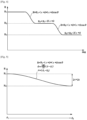
- FIG. 4 is a graph showing a distance from the center of the orbiting scroll 100 to the orbiting wrap 102 in the scroll compressor 1 according to an embodiment of the disclosure.
- FIG. 5 is a graph obtained by enlarging a portion of the graph shown in FIG. 4 .
- FIG. 3 shows an outer surface of the first circular arc portion 110, an outer surface of the second circular arc portion 120, and outer surfaces of the third circular arc portion 131 and the connection portion 140, in the orbiting scroll 100 shown in FIG. 2 .
- R 1 indicates a distance from the center of the orbiting scroll 100 to the first circular arc portion 110
- R 2 indicates a distance from the center of the orbiting scroll 100 to the second circular arc portion 120
- R indicates a distance from the center of the orbiting scroll 100 to the connection portion 140.
- ⁇ 1 indicates an angle of the one end of the connection portion 140 with respect to a preset reference line
- ⁇ 2 indicates an angle of the other end of the connection portion 140 with respect to the preset reference line
- ⁇ indicates an angle of a point of the connection portion 140 with respect to the preset reference line.
- the one end of the connection portion 140 may be a location at which the first circular arc portion 110 is connected to the connection portion 140
- the other end of the connection portion 140 may be a location at which the second circular arc portion 120 is connected to the connection portion 140.
- the distance R 1 from the center of the orbiting scroll 100 to the first circular arc portion 110 may be constant, and the distance R 2 from the center of the orbiting scroll 100 to the second circular arc portion 120 may also be constant.
- the connection portion 140 may connect the first circular arc portion 110 to the second circular arc portion 120 with a variable curvature, and a distance between the connection portion 140 and the center of the orbiting scroll 100 may change successively.
- FIG. 4 is a graph showing a distance from the center of the orbiting scroll 100 to the connection portion 140 according to a change of an angle.
- ⁇ indicates a distance by which the shaft center of the eccentric portion 42 is eccentric from the shaft center of the main shaft 41
- t indicates the thickness of the first circular arc portion 110 and the second circular arc portion 120.
- the distance R from the center of the orbiting scroll 100 to the connection portion 140 may satisfy the following equation.
- R R 1 ⁇ ⁇ + t + ⁇ + t cos ⁇
- connection portion 140 connecting the first circular arc portion 110 to the second circular arc portion 120 is referred to as a first connection portion and a connection portion connecting the second circular arc portion 120 to the third circular arc portion 131 is referred to as a second connection portion
- the distance R between the connection portion and the center of the orbiting scroll 100 from one end of the connection portion 140 to the other end of the connection portion 140 may satisfy the following equation.
- R R 1 ⁇ ⁇ + t + ⁇ + t cos ⁇
- ⁇ ⁇ 180 ⁇ cos ⁇ ⁇ ⁇ 1
- ⁇ ⁇ 1 ⁇ ⁇ 2
- connection portion is in a shape of a cosine curve. Also, it is seen that the connection portion is in a shape of a cosine curve ranging from 0 ° to 180 °, regardless of ⁇ .
- connection portion 140 may be in any one shape of a Bezier curve, a Hermite curve, or a B-spline curve.
- the above-mentioned curves may ensure curvature continuity, and have a high shape degree of freedom due to smooth changes of curvatures.
- FIG. 6 is a top view of an orbiting scroll in a scroll compressor according to another embodiment of the disclosure.
- an orbiting wrap shape of an orbiting scroll will be described as an example, however, the orbiting wrap shape of the orbiting scroll is also applicable to a fixing wrap of a fixed scroll.
- an orbiting scroll 200 may include an end plate 201, and an orbiting wrap protruding above the end plate 201.
- the orbiting wrap may include a first circular arc portion 210 having a constant curvature, a second circular arc portion 220 positioned in an inside of the first circular arc portion 210 and having a constant curvature, and a connection portion 240 connecting the first circular arc portion 210 to the second circular arc portion 220.
- a shaft coupling portion 230 may be positioned, and an outer surface of the shaft coupling portion 230 may form a third circular arc portion 231.
- the third circular arc portion 231 may be in a shape of a small arc of which a center is at the same location as those of the first circular arc portion 210 and the second circular arc portion 220 and which has a smaller radius than the second circular arc portion 220.
- a thickness of the first circular arc portion 210 may be t1.
- a thickness of the second circular arc portion 220 may be t2.
- an included angle ⁇ of a line segment connecting one end of the connection portion 240 to a center of an orbiting scroll 200 and a line segment connecting the other end of the connection portion 240 to the center of the orbiting scroll 200 may be 100 °
- the included angle ⁇ is shown to be 100 °, however, the included angle ⁇ of 100 ° is an example. According to an embodiment of the disclosure, the included angle ⁇ may be 100 ° or more.
- connection portion 240 may be in any one shape of a cosine curve, a Bezier curve, a Hermite curve, or a B-spline curve.
- FIG. 7 is a top view of an orbiting scroll in a scroll compressor according to another embodiment of the disclosure.
- each of a first circular arc portion 310 and a second circular arc portion 320 may include an outer surface and an inner surface. More specifically, the first circular arc portion 310 may include an outer surface 311 and an inner surface 312. The second circular arc portion 320 may include an outer surface 321 and an inner surface 322.
- connection portion may include a first connection portion 340 connecting the first circular arc portion 310 to the second circular arc portion 320, and a second connection portion 350 connecting the second circular arc portion 320 to a shaft coupling portion 330.
- the first connection portion 340 may include an outer surface 341 and an inner surface 342, and the second connection portion 350 may include an outer surface 351 and an inner surface 352.
- the outer surface 341 and the inner surface 342 of the first connection portion 340 may indicate a first connection surface and a second connection surface, respectively.
- the outer surface 351 of the second connection portion 350 may indicate a third connection surface.
- connection portion may include the first connection surface 341 connecting the outer surface 311 of the first circular arc portion 310 to the outer surface 321 of the second circular arc portion 320, the second connection surface 342 connecting the inner surface 312 of the first circular arc portion 310 to the inner surface 322 of the second circular arc portion 320, and the third connection surface 351 connecting the outer surface 321 of the second circular arc portion 320 to a third circular arc portion 331.
- connection portion may be in any one shape of a cosine curve, a Bezier curve, a Hermite curve, or a B-spline curve.
- an included angle of a line segment connecting one end of the first connection surface 341 to a center of an orbiting scroll 300 and a line segment connecting the other end of the first connection surface 341 to the center of the orbiting scroll 300 may be ⁇ 1 .
- an included angle of a line segment connecting one end of the second connection surface 342 to the center of the orbiting scroll 300 and a line segment connecting the other end of the second connection surface 342 to the center of the orbiting scroll 300 may be ⁇ 2 .
- an included angle of a line segment connecting one end of the third connection surface 351 to the center of the orbiting scroll 300 and a line segment connecting the other end of the third connection surface 343 to the center of the orbiting scroll 300 may be ⁇ 3 .
- the included angle ⁇ 1 , the included angle ⁇ 2 , and the included angle ⁇ 3 may be different from each other. More specifically, the included angle ⁇ 3 may be greater than the included angle ⁇ 2 , and the included angle ⁇ 2 may be greater than the included angle ⁇ 1 .
- the included angle ⁇ 1 may be 95 °
- the included angle ⁇ 2 may be 115 °
- the included angle ⁇ 3 may be 135 °.
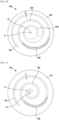
- FIG. 8 is a top view of an orbiting scroll in a scroll compressor according to another embodiment of the disclosure.
- an orbiting scroll 400 may include an end plate 401, and an orbiting wrap protruding above the end plate 401.
- the orbiting wrap may include a first circular arc portion 410 having a constant curvature, a second circular arc portion 420 positioned in an inside of the first circular arc portion 410 and having a constant curvature, and a connection portion 440 connecting the first circular arc portion 410 to the second circular arc portion 420.
- a shaft coupling portion 430 may be positioned, and an outer surface of the shaft coupling portion 430 may form a third circular arc portion 431.
- the third circular arc portion 431 may be in a shape of a small arc of which a center is at the same location as those of the first circular arc portion 410 and the second circular arc portion 420 and which has a smaller radius than the second circular arc portion 420.
- a thickness of the first circular arc portion 410 may be t1.
- a thickness of the second circular arc portion 420 may be t2.
- connection portion may be in any one shape of a cosine curve, a Bezier curve, a Hermite curve, or a B-spline curve.
- the shaft center of the eccentric portion 42 may be eccentric by a preset distance from a center of the orbiting scroll 400.
- the shaft center of the eccentric portion 42 may be eccentric by a distance e in an up direction from the center of the orbiting scroll 400, as shown in FIG. 8 .
- the scroll compressor according to another embodiment of the disclosure may reduce a size of a shaft coupling portion 430. Accordingly, a compression space of the scroll compressor may be expanded, and furthermore, a design volume ratio may increase.
- FIG. 9 is a top view of an orbiting scroll in a scroll compressor according to another embodiment of the disclosure.
- the scroll compressor may be a general scroll compressor, neither a semi shaft penetration scroll compressor nor a shaft penetration scroll compressor.
- the general scroll compressor may have a structure in which an eccentric portion of a rotation shaft is inserted in a boss portion protruding below an end plate 501 of an orbiting scroll 500, wherein an orbiting wrap may be formed over the entire upper area of the end plate 501 of the orbiting scroll 500.
- the general scroll compressor is advantageous in view of a compression space and a design volume ratio.
- the scroll compressor may have a general scroll compressor structure in which an orbiting wrap includes a plurality of circular arc portions 510, 520, and 530 having a constant curvature and connection portions 540, 550, and 560 connecting the circular arc portions 510, 520, and 530 to each other.
- the circular arc portions 510, 520, and 530 may include a first circular arc portion 510, a second circular arc portion 520 positioned in an inside of the first circular arc portion 510 and spaced from the first circular arc portion 510, and a third circular arc portion 530 positioned in an inside of the second circular arc portion 520 and spaced from the second circular arc portion 520.
- connection portions 540, 550, and 560 may include a first connection portion 540 connecting one end of the first circular arc portion 510 to one end of the second circular arc portion 520, a second connection portion 550 connecting the other end of the second circular arc portion 520 to one end of the third circular arc portion 530, and a third connection portion 560 extending from the other end of the third circular arc portion 530.
- Each of the connection portions 540, 550, and 560 may be in a shape of a part of a cosine curve, and have a curvature changing successively between the circular arc portions 510, 520, and 530.
- connection portions 540, 550, and 560 may be in any one shape of a Bezier curve, a Hermite curve, or a B-spline curve.
- a compression space may be expanded compared to a wrap of an involute structure, and a design volume ratio may increase.
- FIG. 10 is a top view of an orbiting scroll in a scroll compressor according to another embodiment of the disclosure.
- an orbiting scroll 600 may have a structure of a semi shaft penetration scroll compressor or a shaft penetration scroll compressor.
- the orbiting scroll 600 may include an end plate 601, and an orbiting wrap protruding above the end plate 601.
- the orbiting wrap may include a circular arc portion 610 having a constant curvature, a shaft coupling portion 620 which is positioned in an inside of the circular arc portion 610 and in which the eccentric portion 42 (see FIG. 1 ) is inserted, and a connection portion 630 connecting the circular arc portion 610 to the shaft coupling portion 620.
- the circular arc portion 610 may be in a shape of an arc having a preset radius.
- the shaft coupling portion 620 may be in a shape of an involute curve of which a center is off set.
- the shaft coupling portion 620 may be in a shape of an involute curve having a center c2 which is off set from a center c1 of the end plate 601 having a circular shape.
- the eccentric portion 42 may be inserted in a center portion of the shaft coupling portion 620.
- connection portion 630 may connect one end of the circular arc portion 610 to one end of the shaft coupling portion 620.
- the connection portion 630 may be in any one shape of a cosine curve, a Bezier curve, a Hermite curve, or a B-spline curve.
- the above-mentioned curves may ensure curvature continuity, and have a high shape degree of freedom due to smooth changes of curvatures.
- connection portion 630 may be in any one shape of a Bezier curve, a Hermite curve, or a B-spline curve.
- the Bezier curve, the Hermite curve, or the B-spline curve is also referred to as a connection curve.
- the thickness t of the orbiting wrap may be optimized by adjusting a weight of the connection curve.
- the connection curve may ensure curvature continuity, and have a high shape degree of freedom due to smooth changes of curvatures.
- FIG. 11 is a top view of an orbiting scroll in a scroll compressor according to another embodiment of the disclosure.
- an orbiting scroll 700 may have a general scroll compressor structure.
- the orbiting scroll 700 may include an end plate 701, and an orbiting wrap protruding above the end plate 701.
- the orbiting wrap may include a circular arc portion 710 having a constant curvature, a curved portion 720 positioned in an inside of the circular arc portion 710, and a connection portion 730 connecting the circular arc portion 710 to the curved portion 720.
- the circular arc portion 710 may be in a shape of an arc having a preset radius.
- the curved portion 720 may be in a shape of an involute curve of which a center is off set. In other words, the curved portion 720 may be in a shape of an involute curve having a center c2 which is off set from a center c1 of the end plate 701 having a circular shape.
- connection portion 730 may connect one end of the circular arc portion 710 to one end of the curved portion 720.
- the connection portion 730 may be in any one shape of a cosine curve, a Bezier curve, a Hermite curve, or a B-spline curve.
- the above-mentioned curves may ensure curvature continuity, and have a high shape degree of freedom due to smooth changes of curvatures.
- connection portion 730 may be in any one shape of a Bezier curve, a Hermite curve, or a B-spline curve.
- the Bezier curve, the Hermite curve, or the B-spline curve is also referred to as a connection curve.
- the thickness t of the orbiting wrap may be optimized by adjusting a weight of the connection curve.
- the wrap thickness t may be finely adjusted.
- the connection curve may ensure curvature continuity and have a high shape degree of freedom due to smooth changes of curvatures.
- the wrap thickness t may be easily optimized.
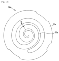
- FIG. 12 is a top view of a fixed scroll corresponding to an orbiting scroll shown in FIG. 11 .
- a fixed scroll 20a may include an end plate 21a being in a shape of a disk, and a fixing wrap 22a extending downward from the end plate 21a and forming a compression chamber 50 (see FIG. 1 ) together with an orbiting wrap.
- FIG. 12 is a top view showing the fixed wrap 20a of the fixed scroll 20a after being arranged to face upward.
- the thickness t of the fixed wrap 22a of the fixed scroll 20a may satisfy the following equation. 2 ⁇ T min ⁇ T max ⁇ 2 ⁇ T min + e
- e represents an eccentric distance
- the eccentric distance is a distance between a center of the rotation shaft 40 and a center of the eccentric portion 42 as shown in FIG. 1 .
- T min represents a minimum thickness of the fixed wrap 22a
- T max represents a maximum thickness of the fixed wrap 22a.
- a thickness of a fixed wrap of a fixed scroll corresponding to the orbiting scroll shown in FIG. 10 may satisfy the following equation. 2 ⁇ T min ⁇ T max ⁇ 2 ⁇ T min + e
- e represents an eccentric distance
- the eccentric distance is a distance between a center of the rotation shaft 40 and a center of the eccentric portion 42 as shown in FIG. 1 .
- T min represents a minimum thickness of the fixed wrap
- T max represents a maximum thickness of the fixed wrap.
Landscapes
- Engineering & Computer Science (AREA)
- Mechanical Engineering (AREA)
- General Engineering & Computer Science (AREA)
- Rotary Pumps (AREA)
Description
- The disclosure relates to a scroll compressor.
- A scroll compressor is a compressor including a fixed scroll having a fixing wrap and an orbiting scroll having an orbiting wrap corresponding to the fixing wrap of the fixed scroll, wherein the orbiting scroll orbits the fixed scroll to form a compression chamber moving continuously between the fixing wrap and the orbiting wrap to inhale and compress a refrigerant.
- The scroll compressor is excellent compared to other types of compressors in view of vibrations and noise that are generated during an operation, because inhalation, compression, and discharge are performed successively.
- In general, in an orbiting scroll of a scroll compressor, an orbiting wrap is formed on one side of a disk-shaped end plate, a boss portion is formed on the other side of the end plate where no orbiting wrap is formed, and a rotation shaft for driving the orbiting scroll is coupled to the boss portion. The scroll compressor is capable of reducing the diameter of the end plate because the orbiting wrap is formed over the entire area of the end plate. However, an action point at which a repulsive force of a refrigerant is applied upon compression is spaced from an action point at which a reaction force for cancelling the repulsive force is applied, so that the behavior of the orbiting scroll may become unstable upon an operation, and accordingly, the scroll compressor may cause great vibrations or noise.
- As an alternative to the scroll compressor described above, a shaft penetration scroll compressor or a semi shaft penetration scroll compressor in which an action point at which a repulsive force of a refrigerant is applied and an action point for cancelling the repulsive force is applied are at the same location has been disclosed. The shaft penetration scroll compressor or the semi shaft penetration scroll compressor prevents an orbiting scroll from being inclined with respect to a rotation shaft, because the action point of the repulsive force of the refrigerant and the action point of the reaction force are at the same location.
- However, the shaft penetration scroll compressor or the semi shaft penetration scroll compressor may not form an orbiting wrap over the entire area of an end plate because the rotation shaft needs to be inserted in the center portion of the end plate. Therefore, a compression space of a compression chamber is reduced, and furthermore, a design volume ratio of the scroll compressor is reduced.
- It is an aspect of the disclosure to provide a scroll compressor capable of increasing a design volume ratio by changing a shape of a wrap.
- It is another aspect of the disclosure to provide a scroll compressor capable of expanding a compression space by changing a shape of a wrap.
- It is another aspect of the disclosure to provide a shaft penetration scroll compressor or a semi shaft penetration scroll compressor capable of increasing a design volume ratio by including a new shape of a wrap structure.
-
- In accordance with the invention , a scroll compressor is provided as defined in
claim 1. - An included angle α of a first line segment connecting one end of the connection portion to a center of the compressing portion and a second line segment connecting the other end of the connection portion to the center of the compressing portion may be 100 ° or more.
- Each of the first circular arc portion and the second circular arc portion may have a constant thickness, and the thickness of the first circular arc portion may be the same as the thickness of the second circular arc portion.
- The compressing portion may further include a shaft coupling portion positioned in an inside of the second circular arc portion and spaced a preset distance from the second circular arc portion, wherein the eccentric portion is coupled to the shaft coupling portion.
- The shaft coupling portion may include a third circular arc portion forming an outer surface of the shaft coupling portion, wherein a curvature of the third circular arc portion is constant.
- A distance between the first circular arc portion and the second circular arc portion may be equal to a distance between the second circular arc portion and the third circular arc portion.
- The connection portion may include: a first connection portion connecting the first circular arc portion to the second circular arc portion, and a second connection portion connecting the second circular arc portion to the third circular arc portion, wherein a curvature of the second connection portion changes from the second circular arc portion to the third circular arc portion.
- Each of the first circular arc portion and the second circular arc portion may include an outer surface and an inner surface, and the third circular arc portion may include an outer surface.
- The first connection portion may include a first connection surface connecting the outer surface of the first circular arc portion to the outer surface of the second circular arc portion, and a second connection surface connecting the inner surface of the first circular arc portion to the inner surface of the second circular arc portion.
- The second connection portion may include a third connection surface connecting the outer surface of the second circular arc portion to the outer surface of the third circular arc portion.
- A first angle which is an included angle of a line segment connecting one end of the first connection surface to the center of the compressing portion and a line segment connecting the other end of the first connection surface to the center of the compressing portion, a second angle which is an included angle of a line segment connecting one end of the second connection surface to the center of the compressing portion and a line segment connecting the other end of the second connection surface to the center of the compressing portion, and a third angle which is an included angle of a line segment connecting one end of the third connection surface to the center of the compressing portion and a line segment connecting the other end of the third connection surface to the center of the compressing portion may be different from each other.
- The first angle may be 95 °, the second angle may be 115 °, and the third angle may be 135 °.
- A center of the shaft coupling portion may be out of a center of the compressing portion.
- The curved portion may be in a shape of an involute curve having a center which is off set from a center of the fixed scroll or the orbiting scroll.
- According to a concept of the disclosure, a scroll compressor capable of increasing a design volume ratio by changing a shape of a wrap may be provided.
- According to a concept of the disclosure, a scroll compressor capable of expanding a compression space by changing a shape of a wrap may be provided.
- According to a concept of the disclosure, a shaft penetration scroll compressor or a semi shaft penetration scroll compressor capable of increasing a design volume ratio by including a new shape of a wrap structure may be provided.
-
-
FIG. 1 is a longitudinal sectional view of a scroll compressor according to an embodiment of the invention ; -
FIG. 2 is a top view of an orbiting scroll in a scroll compressor according to an embodiment of the invention ; -
FIG. 3 schematically shows the orbiting scroll shown inFIG. 2 ; -
FIG. 4 is a graph showing a distance from a center of an orbiting scroll to an orbiting wrap in a scroll compressor according to an embodiment of the invention ; -
FIG. 5 is a graph obtained by enlarging a portion of the graph shown inFIG. 4 ; -
FIG. 6 is a top view of an orbiting scroll in a scroll compressor according to another embodiment of the invention ; -
FIG. 7 is a top view of an orbiting scroll in a scroll compressor according to another embodiment of the invention ; -
FIG. 8 is a top view of an orbiting scroll in a scroll compressor according to another embodiment of the invention ; -
FIG. 9 is a top view of an orbiting scroll in a scroll compressor according to another embodiment of the invention ; -
FIG. 10 is a top view of an orbiting scroll in a scroll compressor according to another embodiment of the invention ; and -
FIG. 11 is a top view of an orbiting scroll in a scroll compressor according to another embodiment of the invention. -
FIG. 12 is a top view of a fixed scroll corresponding to an orbiting scroll shown inFIG. 11 . - Configurations illustrated in the embodiments and the drawings described in the present specification are only the preferred embodiments of the invention , and thus it is to be understood that various modified examples may replace the embodiments and the drawings described in the present specification.
- Also, the terms used in the present specification are merely used to describe embodiments, and are not intended to limit and/or restrict the disclosure. An expression used in the singular encompasses the expression of the plural, unless it has a clearly different meaning in the context. In the present specification, it is to be understood that the terms such as "including" or "having," etc., are intended to indicate the existence of the features, numbers, operations, components, parts, or combinations thereof disclosed in the specification, and are not intended to preclude the possibility that one or more other features, numbers, operations, components, parts, or combinations thereof may exist or may be added.
- Also, it will be understood that, although the terms "first", "second", etc., may be used herein to describe various components, these components should not be limited by these terms. The above terms are used only to distinguish one component from another. For example, a first component discussed below could be termed a second component, and similarly, a second component may be termed a first component without departing from the scope of right of the disclosure.
- In the following description, the terms "front end", "rear end", "upper portion", "lower portion", "upper end", and "lower end" are defined based on the drawings, and the shapes and positions of the corresponding components are not limited by the terms.
- Throughout the disclosure, the expression "at least one of a, b or c" indicates only a, only b, only c, both a and b, both a and c, both b and c, all of a, b, and c, or variations thereof.
-
FIG. 1 is a longitudinal sectional view of a scroll compressor according to an embodiment of the invention. - A
scroll compressor 1 includes amain body 10, afixed scroll 20 fixed inside themain body 10, anorbiting scroll 100 orbiting thefixed scroll 20, compressingportions fixed scroll 20 and the orbitingscroll 100, and a drivingmotor 30 for driving the orbitingscroll 100. - The
main body 10 includes anupper cap 11 and alower cap 12 respectively mounted on a top end and a lower end of themain body 10 to seal an inside of themain body 10, asuction pipe 13 which a refrigerant enters, and adischarge pipe 14 for discharging the refrigerant entered thesuction pipe 13 to an outside of themain body 10 after the refrigerant is compressed. - The
fixed scroll 20 includes afirst end plate 21 being in a shape of a disk, and afixing wrap 22 extending downward from thefirst end plate 21 and forming a compression chamber together with anorbiting wrap 102 which will be described later. - The
orbiting scroll 100 includes asecond end plate 101 being opposite to thefirst end plate 21 and being in a shape of a disk, and theorbiting wrap 102 extending upward from thesecond end plate 101 and forming the compression chamber together with thefixing wrap 22. Also, the orbitingscroll 100 includes ashaft coupling portion 130 in which aneccentric portion 42 of arotation shaft 40 which will be described later is inserted. - Hereinafter, the compressing
portions orbiting scroll 100 and the fixingwrap 22 of the fixedscroll 20. That is, the compressingportions orbiting wrap 102 and the fixingwrap 22. - The fixing
wrap 22 of the fixedscroll 20 are engaged with the orbiting wrap 102 of theorbiting scroll 100 to form acompression chamber 50. Thecompression chamber 50 is formed by the fixedscroll 20 and theorbiting scroll 100, and a volume of thecompression chamber 50 is reduced by an orbiting motion of theorbiting scroll 100. Therefore, a refrigerant entered thecompression chamber 50 is compressed. - A refrigerant entered the
compression chamber 50 and compressed is discharged as a high-pressure refrigerant, and a refrigerant existing inside thecompression chamber 50 presses theorbiting scroll 100 in a direction in which theorbiting scroll 100 is away from the fixedscroll 20. - Because inside pressure of the
compression chamber 50 is applied in a direction in which theorbiting scroll 100 is away from the fixedscroll 20, aback pressure chamber 18 for transferring pressure in a direction in which theorbiting scroll 100 faces the fixedscroll 20 may be provided below theorbiting scroll 100. - A refrigerant may be filled in an inside of the
back pressure chamber 18. Theback pressure chamber 18 may be formed by amain frame 15, therotation shaft 40, and theorbiting scroll 100. - An Oldham's
ring 17 for orbiting theorbiting scroll 100 without revolving theorbiting scroll 100 may be provided between the orbitingscroll 100 and themain frame 15. - The
main frame 15 and asub frame 16 may be respectively fixed on upper and lower portions of an inner surface of themain body 10, and the drivingmotor 30 may be positioned between themain frame 15 and thesub frame 16. - The driving
motor 30 may include astator 31 and arotor 32. - The
stator 31 may include astator body 311, and acoil 312 wound around thestator body 311. - The
stator body 311 may be a laminate formed by stacking a plurality of electrical steel sheets, and may be substantially in a shape of a cylinder, wherein a diameter of an outer circumference surface of thestator body 311 may be larger than a diameter of an inner circumference surface of themain body 10, and therefore, thestator body 311 may be fitted in themain body 10 by interference fit. - The
stator body 311 may include a plurality of teeth (not shown) arranged in a circumference direction on the inner portion that is opposite to an outer circumference of therotor 32. Thecoil 312 may be positioned at a slot (not shown) existing between neighboring teeth. - The
rotor 32 may be a laminate formed by stacking a plurality of electrical steel sheets each being in a shape of a ring. A diameter of an inner circumference surface of therotor 32 may be smaller than a diameter of an outer circumference surface of therotation shaft 40. Therotation shaft 40 may be fitted in therotor 32 by interference fit. A method of fitting therotation shaft 40 in therotor 32 may be press-fit. Therefore, therotation shaft 40 may rotate together with therotor 32. - The
rotation shaft 40 includes amain shaft 41 inserted in therotor 32, and aneccentric portion 42 positioned at an upper portion of themain shaft 41 and having a shaft center being eccentric from a shaft center of themain shaft 41. - The
rotation shaft 40 may be installed between themain frame 15 and thesub frame 16 to transfer a rotation force generated by the drivingmotor 30 to theorbiting scroll 100. - An upper portion of the
rotation shaft 40 may be supported by themain frame 15 in such a way to be rotatable with respect to themain frame 15. Themain frame 15 may include amain bearing 15a for supporting rotations of therotation shaft 40. - A lower portion of the
rotation shaft 40 may be supported by thesub frame 16 in such a way to be rotatable with respect to thesub frame 16. Thesub frame 16 may include asub bearing 16a for supporting rotations of therotation shaft 40. - The
orbiting scroll 100 may include theshaft coupling portion 130 in which theeccentric portion 42 is inserted. According to an embodiment of the disclosure, theshaft coupling portion 130 may protrude upward from thesecond end plate 101 of theorbiting scroll 100. By the structure, theeccentric portion 42 may protrude upward from thesecond end plate 101, and theeccentric portion 42 may be positioned alongside theorbiting wrap 102 and the fixingwrap 22. - The
orbiting scroll 100 may include anorbiting bearing 42a positioned on an inner surface of theshaft coupling portion 130. Theorbiting bearing 42a may support rotations of theeccentric portion 42. - The above-described structure of the
orbiting scroll 100 is referred to as a semi shaft penetration structure, and hereinafter, a semi shaft penetration scroll compressor will be described as an example. However, the disclosure is not limited to the semi shaft penetration scroll compressor, and may be applied to a shaft penetration scroll compressor. - In the case of the semi shaft penetration scroll compressor or the shaft penetration scroll compressor, because an action point at which a repulsive force of a refrigerant is applied upon compression and an action point at which a reaction force for cancelling the repulsive force is applied are at the same location, vibrations or noise that may be caused by an inclination of an orbiting scroll may be prevented. However, in the case of the semi shaft penetration scroll compressor or the shaft penetration scroll compressor, a rotation shaft needs to be inserted in a center of an end plate of an orbiting scroll. Therefore, it is difficult to form an orbiting wrap over the entire area of the end plate, and accordingly, a compression space and a design volume ratio may be reduced. According to a concept of the disclosure, a scroll compressor capable of expanding a compression space and increasing a design volume ratio by improving a wrap shape while having a semi shaft penetration structure or a shaft penetration structure is disclosed.
-
FIG. 2 is a top view of theorbiting scroll 100 in thescroll compressor 1 according to an embodiment of the disclosure. - Hereinafter, an orbiting wrap shape of the
orbiting scroll 100 will be described as an example. Due to characteristics of thescroll compressor 1, because a fixing wrap shape of the fixedscroll 20 corresponds to the orbiting wrap shape, the following descriptions may also be applicable to the fixingwrap 22 of the fixedscroll 20. - Referring to
FIG. 2 , theorbiting scroll 100 according to an embodiment of the disclosure may include thesecond end plate 101, and an orbiting wrap protruding upward from thesecond end plate 101. - The orbiting wrap may include a first
circular arc portion 110 having a constant curvature, a secondcircular arc portion 120 positioned in an inside of the firstcircular arc portion 110 and having a constant curvature, and aconnection portion 140 connecting the firstcircular arc portion 110 to the secondcircular arc portion 120. - The first
circular arc portion 110 may be in a shape of an arc having a preset radius. The secondcircular arc portion 120 may also be in a shape of a arc, like the firstcircular arc portion 110, wherein a center of the secondcircular arc portion 120 may be at the same location as that of the firstcircular arc portion 110 and the radius of the secondcircular arc portion 120 may be smaller than that of the firstcircular arc portion 110. - In an inside of the second
circular arc portion 120, theshaft coupling portion 130 may be positioned. An outer surface of theshaft coupling portion 130 may form a thirdcircular arc portion 131. A center of the thirdcircular arc portion 131 may be at the same location as those of the firstcircular arc portion 110 and the secondcircular arc portion 120, and the thirdcircular arc portion 131 may be in a shape of anarc of which a radius is smaller than that of the secondcircular arc portion 120. - The first
circular arc portion 110 may have a thickness t1, and the secondcircular arc portion 120 may have a thickness t2. - According to an embodiment of the disclosure, the thickness t1 of the first
circular arc portion 110 may be the same as the thickness t2 of the secondcircular arc portion 120. Accordingly, t1 = t2. - Also, a distance d1 between the first
circular arc portion 110 and the secondcircular arc portion 120 may be equal to a distance d2 between the secondcircular arc portion 120 and the thirdcircular arc portion 131. Accordingly, d1 = d2. - Because each of the first
circular arc portion 110 and the secondcircular arc portion 120 is formed in a shape of an arc which is a part of a circle having a constant radius, each of the firstcircular arc portion 110 and the secondcircular arc portion 120 may have a constant curvature. - According to a concept of the disclosure, the
connection portion 140 connecting the firstcircular arc portion 110 to the secondcircular arc portion 120 may have a curvature changing from the firstcircular portion 110 to the secondcircular portion 120. The curvature of theconnection portion 140 may change successively from the firstcircular arc portion 110 to the secondcircular arc portion 120. Theconnection portion 140 may be in any one shape of a cosine curve, a Bezier curve, a Hermite curve, or a B-spline curve. A detailed shape of theconnection portion 140 will be described later. - According to an embodiment of the disclosure, an included angle α of a line segment connecting one end of the
connection portion 140 to a center of theorbiting scroll 100 and a line segment connecting the other end of theconnection portion 140 to the center of theorbiting scroll 100 may be 135 °. The one end of theconnection portion 140 may be a location at which the firstcircular arc portion 110 is connected to theconnection portion 140, and the other end of theconnection portion 140 may be a location at which the secondcircular arc portion 120 is connected to theconnection portion 140. -
FIG. 3 schematically shows theorbiting scroll 100 shown inFIG. 2 .FIG. 4 is a graph showing a distance from the center of theorbiting scroll 100 to theorbiting wrap 102 in thescroll compressor 1 according to an embodiment of the disclosure.FIG. 5 is a graph obtained by enlarging a portion of the graph shown inFIG. 4 . -
FIG. 3 shows an outer surface of the firstcircular arc portion 110, an outer surface of the secondcircular arc portion 120, and outer surfaces of the thirdcircular arc portion 131 and theconnection portion 140, in theorbiting scroll 100 shown inFIG. 2 . - In
FIG. 3 , R1 indicates a distance from the center of theorbiting scroll 100 to the firstcircular arc portion 110, R2 indicates a distance from the center of theorbiting scroll 100 to the secondcircular arc portion 120, and R indicates a distance from the center of theorbiting scroll 100 to theconnection portion 140. - Also, θ1 indicates an angle of the one end of the
connection portion 140 with respect to a preset reference line, θ2 indicates an angle of the other end of theconnection portion 140 with respect to the preset reference line, and θ indicates an angle of a point of theconnection portion 140 with respect to the preset reference line. The one end of theconnection portion 140 may be a location at which the firstcircular arc portion 110 is connected to theconnection portion 140, and the other end of theconnection portion 140 may be a location at which the secondcircular arc portion 120 is connected to theconnection portion 140. - Referring to
FIG. 3 , the distance R1 from the center of theorbiting scroll 100 to the firstcircular arc portion 110 may be constant, and the distance R2 from the center of theorbiting scroll 100 to the secondcircular arc portion 120 may also be constant. Theconnection portion 140 may connect the firstcircular arc portion 110 to the secondcircular arc portion 120 with a variable curvature, and a distance between theconnection portion 140 and the center of theorbiting scroll 100 may change successively. -
FIG. 4 is a graph showing a distance from the center of theorbiting scroll 100 to theconnection portion 140 according to a change of an angle. - In
FIG. 4 , ε indicates a distance by which the shaft center of theeccentric portion 42 is eccentric from the shaft center of themain shaft 41, and t indicates the thickness of the firstcircular arc portion 110 and the secondcircular arc portion 120. - As shown in
FIG. 4 , the distance R from the center of theorbiting scroll 100 to theconnection portion 140 may satisfy the following equation.
- When the
connection portion 140 connecting the firstcircular arc portion 110 to the secondcircular arc portion 120 is referred to as a first connection portion and a connection portion connecting the secondcircular arc portion 120 to the thirdcircular arc portion 131 is referred to as a second connection portion, a distance R between the second connection portion and the center of theorbiting scroll 100 may satisfy the following equation.
- More specifically, referring to
FIG. 5 , the distance R between the connection portion and the center of the orbiting scroll 100 from one end of theconnection portion 140 to the other end of theconnection portion 140 may satisfy the following equation.
- It is seen from the above equation that the connection portion is in a shape of a cosine curve. Also, it is seen that the connection portion is in a shape of a cosine curve ranging from 0 ° to 180 °, regardless of α.
- Although not shown in the drawings, according to another embodiment of the disclosure, the
connection portion 140 may be in any one shape of a Bezier curve, a Hermite curve, or a B-spline curve. The above-mentioned curves may ensure curvature continuity, and have a high shape degree of freedom due to smooth changes of curvatures. - Hereinafter, various embodiments of the disclosure will be described. In the following embodiments, descriptions about the same components as those described above in the above-described embodiments will be omitted.
-
FIG. 6 is a top view of an orbiting scroll in a scroll compressor according to another embodiment of the disclosure. As described above, an orbiting wrap shape of an orbiting scroll will be described as an example, however, the orbiting wrap shape of the orbiting scroll is also applicable to a fixing wrap of a fixed scroll. - Referring to
FIG. 6 , anorbiting scroll 200 may include anend plate 201, and an orbiting wrap protruding above theend plate 201. The orbiting wrap may include a firstcircular arc portion 210 having a constant curvature, a secondcircular arc portion 220 positioned in an inside of the firstcircular arc portion 210 and having a constant curvature, and aconnection portion 240 connecting the firstcircular arc portion 210 to the secondcircular arc portion 220. In an inside of the secondcircular arc portion 220, ashaft coupling portion 230 may be positioned, and an outer surface of theshaft coupling portion 230 may form a thirdcircular arc portion 231. The thirdcircular arc portion 231 may be in a shape of a small arc of which a center is at the same location as those of the firstcircular arc portion 210 and the secondcircular arc portion 220 and which has a smaller radius than the secondcircular arc portion 220. - A thickness of the first
circular arc portion 210 may be t1. A thickness of the secondcircular arc portion 220 may be t2. The thickness t1 of the firstcircular arc portion 210 may be equal to the thickness t2 of the secondcircular arc portion 220. Accordingly, t1=t2 may be satisfied. Also, a distance d1 between the firstcircular arc portion 210 and the secondcircular arc portion 220 may be equal to a distance d2 between the secondcircular arc portion 220 and the thirdcircular arc portion 231. Accordingly, d1=d2 may be satisfied. - According to another embodiment of the disclosure, an included angle α of a line segment connecting one end of the
connection portion 240 to a center of anorbiting scroll 200 and a line segment connecting the other end of theconnection portion 240 to the center of theorbiting scroll 200 may be 100 ° InFIG. 6 , the included angle α is shown to be 100 °, however, the included angle α of 100 ° is an example. According to an embodiment of the disclosure, the included angle α may be 100 ° or more. - The
connection portion 240 may be in any one shape of a cosine curve, a Bezier curve, a Hermite curve, or a B-spline curve.FIG. 7 is a top view of an orbiting scroll in a scroll compressor according to another embodiment of the disclosure. - Referring to
FIG. 7 , each of a firstcircular arc portion 310 and a secondcircular arc portion 320 may include an outer surface and an inner surface. More specifically, the firstcircular arc portion 310 may include anouter surface 311 and aninner surface 312. The secondcircular arc portion 320 may include anouter surface 321 and aninner surface 322. - Also, a connection portion may include a
first connection portion 340 connecting the firstcircular arc portion 310 to the secondcircular arc portion 320, and asecond connection portion 350 connecting the secondcircular arc portion 320 to ashaft coupling portion 330. - The
first connection portion 340 may include anouter surface 341 and aninner surface 342, and thesecond connection portion 350 may include anouter surface 351 and aninner surface 352. Hereinafter, theouter surface 341 and theinner surface 342 of thefirst connection portion 340 may indicate a first connection surface and a second connection surface, respectively. Theouter surface 351 of thesecond connection portion 350 may indicate a third connection surface. - According to another embodiment of the disclosure, the connection portion may include the
first connection surface 341 connecting theouter surface 311 of the firstcircular arc portion 310 to theouter surface 321 of the secondcircular arc portion 320, thesecond connection surface 342 connecting theinner surface 312 of the firstcircular arc portion 310 to theinner surface 322 of the secondcircular arc portion 320, and thethird connection surface 351 connecting theouter surface 321 of the secondcircular arc portion 320 to a thirdcircular arc portion 331. - The connection portion may be in any one shape of a cosine curve, a Bezier curve, a Hermite curve, or a B-spline curve.
- Referring to
FIG. 7 , an included angle of a line segment connecting one end of thefirst connection surface 341 to a center of anorbiting scroll 300 and a line segment connecting the other end of thefirst connection surface 341 to the center of theorbiting scroll 300 may be α1. Also, an included angle of a line segment connecting one end of thesecond connection surface 342 to the center of theorbiting scroll 300 and a line segment connecting the other end of thesecond connection surface 342 to the center of theorbiting scroll 300 may be α2. Also, an included angle of a line segment connecting one end of thethird connection surface 351 to the center of theorbiting scroll 300 and a line segment connecting the other end of the third connection surface 343 to the center of theorbiting scroll 300 may be α3. - According to another embodiment of the disclosure, the included angle α1, the included angle α2, and the included angle α3 may be different from each other. More specifically, the included angle α3 may be greater than the included angle α2, and the included angle α2 may be greater than the included angle α1. For example, as shown in
FIG. 7 , the included angle α1 may be 95 °, the included angle α2 may be 115 °, and the included angle α3 may be 135 °. -
FIG. 8 is a top view of an orbiting scroll in a scroll compressor according to another embodiment of the disclosure. - Referring to
FIG. 8 , anorbiting scroll 400 may include anend plate 401, and an orbiting wrap protruding above theend plate 401. The orbiting wrap may include a firstcircular arc portion 410 having a constant curvature, a secondcircular arc portion 420 positioned in an inside of the firstcircular arc portion 410 and having a constant curvature, and aconnection portion 440 connecting the firstcircular arc portion 410 to the secondcircular arc portion 420. In an inside of the secondcircular arc portion 420, ashaft coupling portion 430 may be positioned, and an outer surface of theshaft coupling portion 430 may form a thirdcircular arc portion 431. The thirdcircular arc portion 431 may be in a shape of a small arc of which a center is at the same location as those of the firstcircular arc portion 410 and the secondcircular arc portion 420 and which has a smaller radius than the secondcircular arc portion 420. - A thickness of the first
circular arc portion 410 may be t1. A thickness of the secondcircular arc portion 420 may be t2. The thickness t1 of the firstcircular arc portion 410 may be equal to the thickness t2 of the secondcircular arc portion 420. Accordingly, t1=t2 may be satisfied. Also, a distance d1 between the firstcircular arc portion 410 and the secondcircular arc portion 420 may be equal to a distance d2 between the secondcircular arc portion 420 and the thirdcircular arc portion 431. Accordingly, d1=d2 may be satisfied. - The connection portion may be in any one shape of a cosine curve, a Bezier curve, a Hermite curve, or a B-spline curve. Referring to
FIG. 8 , in the scroll compressor according to another embodiment of the disclosure, the shaft center of theeccentric portion 42 may be eccentric by a preset distance from a center of theorbiting scroll 400. For example, the shaft center of theeccentric portion 42 may be eccentric by a distance e in an up direction from the center of theorbiting scroll 400, as shown inFIG. 8 . Through the structure, the scroll compressor according to another embodiment of the disclosure may reduce a size of ashaft coupling portion 430. Accordingly, a compression space of the scroll compressor may be expanded, and furthermore, a design volume ratio may increase. -
FIG. 9 is a top view of an orbiting scroll in a scroll compressor according to another embodiment of the disclosure. - Referring to
FIG. 9 , according to another embodiment of the disclosure, the scroll compressor may be a general scroll compressor, neither a semi shaft penetration scroll compressor nor a shaft penetration scroll compressor. The general scroll compressor may have a structure in which an eccentric portion of a rotation shaft is inserted in a boss portion protruding below anend plate 501 of anorbiting scroll 500, wherein an orbiting wrap may be formed over the entire upper area of theend plate 501 of theorbiting scroll 500. The general scroll compressor is advantageous in view of a compression space and a design volume ratio. - According to another embodiment of the disclosure, the scroll compressor may have a general scroll compressor structure in which an orbiting wrap includes a plurality of
circular arc portions connection portions circular arc portions circular arc portions circular arc portion 510, a secondcircular arc portion 520 positioned in an inside of the firstcircular arc portion 510 and spaced from the firstcircular arc portion 510, and a thirdcircular arc portion 530 positioned in an inside of the secondcircular arc portion 520 and spaced from the secondcircular arc portion 520. Theconnection portions first connection portion 540 connecting one end of the firstcircular arc portion 510 to one end of the secondcircular arc portion 520, asecond connection portion 550 connecting the other end of the secondcircular arc portion 520 to one end of the thirdcircular arc portion 530, and athird connection portion 560 extending from the other end of the thirdcircular arc portion 530. Each of theconnection portions circular arc portions connection portions -
FIG. 10 is a top view of an orbiting scroll in a scroll compressor according to another embodiment of the disclosure. - Referring to
FIG. 10 , anorbiting scroll 600 may have a structure of a semi shaft penetration scroll compressor or a shaft penetration scroll compressor. Theorbiting scroll 600 may include anend plate 601, and an orbiting wrap protruding above theend plate 601. The orbiting wrap may include acircular arc portion 610 having a constant curvature, ashaft coupling portion 620 which is positioned in an inside of thecircular arc portion 610 and in which the eccentric portion 42 (seeFIG. 1 ) is inserted, and aconnection portion 630 connecting thecircular arc portion 610 to theshaft coupling portion 620. - The
circular arc portion 610 may be in a shape of an arc having a preset radius. Theshaft coupling portion 620 may be in a shape of an involute curve of which a center is off set. In other words, theshaft coupling portion 620 may be in a shape of an involute curve having a center c2 which is off set from a center c1 of theend plate 601 having a circular shape. Theeccentric portion 42 may be inserted in a center portion of theshaft coupling portion 620. - The
connection portion 630 may connect one end of thecircular arc portion 610 to one end of theshaft coupling portion 620. Theconnection portion 630 may be in any one shape of a cosine curve, a Bezier curve, a Hermite curve, or a B-spline curve. The above-mentioned curves may ensure curvature continuity, and have a high shape degree of freedom due to smooth changes of curvatures. - Also, as described above, the
connection portion 630 may be in any one shape of a Bezier curve, a Hermite curve, or a B-spline curve. Hereinafter, the Bezier curve, the Hermite curve, or the B-spline curve is also referred to as a connection curve. - According to another embodiment of the disclosure, because the
connection portion 630 is in a shape of a connection curve, the thickness t of the orbiting wrap may be optimized by adjusting a weight of the connection curve. In other words, by adjusting a weight of the connection curve in a process of optimizing the thickness of the orbiting wrap, the thickness t of the orbiting wrap may be finely adjusted. As described above, the connection curve may ensure curvature continuity, and have a high shape degree of freedom due to smooth changes of curvatures. By adjusting the weight using the characteristic of the connection curve, the wrap thickness t may be easily optimized. -
FIG. 11 is a top view of an orbiting scroll in a scroll compressor according to another embodiment of the disclosure. - Referring to
FIG. 11 , anorbiting scroll 700 may have a general scroll compressor structure. Theorbiting scroll 700 may include anend plate 701, and an orbiting wrap protruding above theend plate 701. The orbiting wrap may include acircular arc portion 710 having a constant curvature, acurved portion 720 positioned in an inside of thecircular arc portion 710, and aconnection portion 730 connecting thecircular arc portion 710 to thecurved portion 720. - The
circular arc portion 710 may be in a shape of an arc having a preset radius. Thecurved portion 720 may be in a shape of an involute curve of which a center is off set. In other words, thecurved portion 720 may be in a shape of an involute curve having a center c2 which is off set from a center c1 of theend plate 701 having a circular shape. - The
connection portion 730 may connect one end of thecircular arc portion 710 to one end of thecurved portion 720. Theconnection portion 730 may be in any one shape of a cosine curve, a Bezier curve, a Hermite curve, or a B-spline curve. The above-mentioned curves may ensure curvature continuity, and have a high shape degree of freedom due to smooth changes of curvatures. - Also, as described above, the
connection portion 730 may be in any one shape of a Bezier curve, a Hermite curve, or a B-spline curve. Hereinafter, the Bezier curve, the Hermite curve, or the B-spline curve is also referred to as a connection curve. - According to another embodiment of the disclosure, because the
connection portion 730 is in a shape of a connection curve, the thickness t of the orbiting wrap may be optimized by adjusting a weight of the connection curve. In other words, by adjusting a weight of the connection curve in a process of optimizing the thickness of the orbiting wrap, the wrap thickness t may be finely adjusted. As described above, the connection curve may ensure curvature continuity and have a high shape degree of freedom due to smooth changes of curvatures. By adjusting the weight using the characteristic of the connection curve, the wrap thickness t may be easily optimized. -
FIG. 12 is a top view of a fixed scroll corresponding to an orbiting scroll shown inFIG. 11 . - Referring to
FIG. 12 , afixed scroll 20a may include anend plate 21a being in a shape of a disk, and a fixingwrap 22a extending downward from theend plate 21a and forming a compression chamber 50 (seeFIG. 1 ) together with an orbiting wrap.FIG. 12 is a top view showing the fixedwrap 20a of the fixedscroll 20a after being arranged to face upward. - According to another embodiment of the disclosure, the thickness t of the fixed
wrap 22a of the fixedscroll 20a may satisfy the following equation.
- Herein, e represents an eccentric distance, and the eccentric distance is a distance between a center of the
rotation shaft 40 and a center of theeccentric portion 42 as shown inFIG. 1 . Also, Tmin represents a minimum thickness of the fixedwrap 22a, and Tmax represents a maximum thickness of the fixedwrap 22a. According to another embodiment of the disclosure, when the thickness t of the fixedwrap 22a satisfies the above equation, a technical effect of reductions of a trust area and trust loss through optimization of the fixed wrap thickness may be achieved. - Although not shown in the drawing, a thickness of a fixed wrap of a fixed scroll corresponding to the orbiting scroll shown in
FIG. 10 may satisfy the following equation.
- Herein, e represents an eccentric distance, and the eccentric distance is a distance between a center of the
rotation shaft 40 and a center of theeccentric portion 42 as shown inFIG. 1 . Also, Tmin represents a minimum thickness of the fixed wrap, and Tmax represents a maximum thickness of the fixed wrap. According to another embodiment of the disclosure, when the thickness t of the fixed wrap satisfies the above equation, a technical effect of reductions of a trust area and trust loss through optimization of the fixed wrap thickness may be achieved. - Although a few embodiments of the disclosure have been shown and described, it would be appreciated by those skilled in the art that changes may be made in these embodiments without departing from the principles of the invention the scope of which is defined in the appended claims.
Claims (12)
- A scroll compressor comprising:a main body (10);a fixed scroll (20) fixed inside the main body;an orbiting scroll (100) orbiting the fixed scroll;a plurality of compressing portions (22, 100) respectively provided in the fixed scroll and the orbiting scroll, anda rotation shaft (40) rotating with respect to a rotation axis and including an eccentric portion (42) being eccentric from the rotation axis, wherein the eccentric portion is positioned alongside the compressing portion in a direction crossing the rotation axis, andwherein each compressing portion comprisesa circular arc portion (110) of which a curvature is constant,a curved portion (120) positioned in an inside of the circular arc portion and spaced a preset distance from the circular arc portion, anda connection portion (140) connecting the circular arc portion to the curved portion, wherein a curvature of the connection portion changes from the circular arc portion to the curved portion,characterized in thatthe connection portion is in a shape of one of a cosine curve, a Bezier curve, a Hermite curve, and a B-spline curve, andwhen the curved portion is in a shape of an arc of which a curvature is constant, the circular arc portion is referred to as a first circular arc portion, and the curved portion is referred to as a second circular arc portion,wherein,when a distance from a center of the compressing portion to the connection portion is R,a distance from the center of the compressing portion to the first circular arc portion is R1,a distance from the center of the compressing portion to the second circular arc portion is R2, a thickness of the first circular arc portion is t,a distance by which a center of the eccentric portion is eccentric from a center of the rotation shaft is ε,an angle of one end of the first circular arc portion with respect to a preset reference line is θ1,an angle of one end of the second circular arc portion with respect to the preset reference line is θ2, andan angle of a point of the connection portion with respect to the preset reference line is θ,

- The scroll compressor of claim 1, wherein an included angle α of a first line segment connecting one end of the connection portion to a center of the compressing portion and a second line segment connecting the other end of the connection portion to the center of the compressing portion is 100 ° or more.
- The scroll compressor of claim 1, wherein each of the first circular arc portion and the second circular arc portion has a constant thickness, and
the thickness of the first circular arc portion is the same as the thickness of the second circular arc portion. - The scroll compressor of claim 1, wherein the compressing portion further comprises a shaft coupling portion (130) positioned in an inside of the second circular arc portion and spaced a preset distance from the second circular arc portion, wherein the eccentric portion is coupled to the shaft coupling portion,
wherein the shaft coupling portion (130) comprises a third circular arc portion forming an outer surface of the shaft coupling portion, wherein a curvature of the third circular arc portion is constant. - The scroll compressor of claim 4, wherein a distance between the first circular arc portion and the second circular arc portion is equal to a distance between the second circular arc portion and the third circular arc portion.
- The scroll compressor of claim 4, wherein the connection portion (140) comprises:a first connection portion connecting the first circular arc portion to the second circular arc portion, anda second connection portion connecting the second circular arc portion to the third circular arc portion, wherein a curvature of the second connection portion changes from the second circular arc portion to the third circular arc portion.
- The scroll compressor of claim 6, wherein each of the first circular arc portion and the second circular arc portion includes an outer surface and an inner surface, and
the third circular arc portion includes an outer surface. - The scroll compressor of claim 7, whereinthe first connection portion comprises a first connection surface connecting the outer surface of the first circular arc portion to the outer surface of the second circular arc portion, and a second connection surface connecting the inner surface of the first circular arc portion to the inner surface of the second circular arc portion, andthe second connection portion comprises a third connection surface connecting the outer surface of the second circular arc portion to the outer surface of the third circular arc portion.
- The scroll compressor of claim 8, wherein a first angle which is an included angle of a line segment connecting one end of the first connection surface to the center of the compressing portion and a line segment connecting the other end of the first connection surface to the center of the compressing portion,a second angle which is an included angle of a line segment connecting one end of the second connection surface to the center of the compressing portion and a line segment connecting the other end of the second connection surface to the center of the compressing portion, anda third angle which is an included angle of a line segment connecting one end of the third connection surface to the center of the compressing portion and a line segment connecting the other end of the third connection surface to the center of the compressing portion are different from each other.
- The scroll compressor of claim 9, wherein the first angle is 95 °, the second angle is 115 °, and the third angle is 135 °.
- The scroll compressor of claim 4, wherein a center of the shaft coupling portion (230) is out of a center of the compressing portion.
- The scroll compressor of claim 1, wherein the curved portion (120) is in a shape of an involute curve having a center which is off set from a center of the fixed scroll or the orbiting scroll.
Applications Claiming Priority (3)
| Application Number | Priority Date | Filing Date | Title |
|---|---|---|---|
| KR20190092268 | 2019-07-30 | ||
| KR1020200086090A KR102821449B1 (en) | 2019-07-30 | 2020-07-13 | Scroll compressor |
| PCT/KR2020/009919 WO2021020858A1 (en) | 2019-07-30 | 2020-07-28 | Scroll compressor |
Publications (3)
| Publication Number | Publication Date |
|---|---|
| EP3990785A1 EP3990785A1 (en) | 2022-05-04 |
| EP3990785A4 EP3990785A4 (en) | 2022-08-31 |
| EP3990785B1 true EP3990785B1 (en) | 2024-10-30 |
Family
ID=74228756
Family Applications (1)
| Application Number | Title | Priority Date | Filing Date |
|---|---|---|---|
| EP20847631.7A Active EP3990785B1 (en) | 2019-07-30 | 2020-07-28 | Scroll compressor |
Country Status (3)
| Country | Link |
|---|---|
| US (1) | US11454237B2 (en) |
| EP (1) | EP3990785B1 (en) |
| WO (1) | WO2021020858A1 (en) |
Families Citing this family (1)
| Publication number | Priority date | Publication date | Assignee | Title |
|---|---|---|---|---|
| JPWO2024257266A1 (en) * | 2023-06-14 | 2024-12-19 |
Family Cites Families (25)
| Publication number | Priority date | Publication date | Assignee | Title |
|---|---|---|---|---|
| JP2932013B2 (en) | 1991-06-27 | 1999-08-09 | 株式会社日立製作所 | Scroll compressor |
| TW253929B (en) * | 1992-08-14 | 1995-08-11 | Mind Tech Corp | |
| US5318424A (en) * | 1992-12-07 | 1994-06-07 | Carrier Corporation | Minimum diameter scroll component |
| JP3170111B2 (en) | 1993-09-24 | 2001-05-28 | 株式会社日立製作所 | Scroll compressor |
| JPH07310681A (en) * | 1994-05-19 | 1995-11-28 | Toyo A Tec Kk | Scroll type compressor |
| KR0136844B1 (en) * | 1994-11-21 | 1998-07-01 | 박기영 | Scroll Scroll Scroll |
| JP3708573B2 (en) | 1994-12-16 | 2005-10-19 | 株式会社日立製作所 | Shaft-through two-stage scroll compressor |
| JP3110970B2 (en) | 1995-02-24 | 2000-11-20 | 株式会社日立製作所 | Shaft penetrating scroll compressor |
| JP3194076B2 (en) * | 1995-12-13 | 2001-07-30 | 株式会社日立製作所 | Scroll type fluid machine |
| JP2001221169A (en) | 2000-09-09 | 2001-08-17 | 哲哉 ▲荒▼田 | Multiple connection type scroll compressor |
| KR100531833B1 (en) * | 2004-02-23 | 2005-11-30 | 엘지전자 주식회사 | Capacity changeable apparatus for scroll compressor |
| JP2012097677A (en) * | 2010-11-03 | 2012-05-24 | Denso Corp | Variable displacement scroll compressor |
| JP2012241631A (en) | 2011-05-20 | 2012-12-10 | Hitachi Appliances Inc | Shaft-through scroll compressor |
| JP5187418B2 (en) * | 2011-07-15 | 2013-04-24 | ダイキン工業株式会社 | Scroll compressor |
| KR101282227B1 (en) | 2011-09-21 | 2013-07-09 | 엘지전자 주식회사 | Scroll compressor |
| KR20130031734A (en) * | 2011-09-21 | 2013-03-29 | 엘지전자 주식회사 | Scroll compressor |
| KR20130031736A (en) | 2011-09-21 | 2013-03-29 | 엘지전자 주식회사 | Scroll compressor |
| KR101285618B1 (en) | 2011-09-28 | 2013-07-12 | 엘지전자 주식회사 | Scroll compressor |
| KR101285619B1 (en) | 2011-09-28 | 2013-07-12 | 엘지전자 주식회사 | Scroll compressor |
| JP5506839B2 (en) | 2012-02-29 | 2014-05-28 | 日立アプライアンス株式会社 | Scroll compressor and air conditioner |
| JP2013194721A (en) | 2012-03-23 | 2013-09-30 | Hitachi Appliances Inc | Shaft-through scroll compressor |
| KR102051095B1 (en) * | 2013-06-10 | 2019-12-02 | 엘지전자 주식회사 | Scroll compressor |
| KR102245438B1 (en) | 2014-08-19 | 2021-04-29 | 엘지전자 주식회사 | compressor |
| KR102481368B1 (en) * | 2016-04-26 | 2022-12-26 | 엘지전자 주식회사 | Scroll compressor |
| KR102385789B1 (en) * | 2017-09-01 | 2022-04-13 | 삼성전자주식회사 | Scroll compressor |
-
2020
- 2020-07-28 EP EP20847631.7A patent/EP3990785B1/en active Active
- 2020-07-28 WO PCT/KR2020/009919 patent/WO2021020858A1/en not_active Ceased
- 2020-07-29 US US16/942,190 patent/US11454237B2/en active Active
Also Published As
| Publication number | Publication date |
|---|---|
| EP3990785A4 (en) | 2022-08-31 |
| EP3990785A1 (en) | 2022-05-04 |
| US20210033092A1 (en) | 2021-02-04 |
| WO2021020858A1 (en) | 2021-02-04 |
| US11454237B2 (en) | 2022-09-27 |
Similar Documents
| Publication | Publication Date | Title |
|---|---|---|
| EP2497953B1 (en) | Scroll compressor | |
| EP2581605B1 (en) | Scroll compressor with bypass hole | |
| US9765781B2 (en) | Scroll compressor | |
| CN111033044B (en) | Scroll compressor having a discharge port | |
| CN103032323A (en) | Scroll compressor with oldham ring | |
| US7320579B2 (en) | Roots type fluid machine | |
| US20130078129A1 (en) | Scroll compressor | |
| US11454237B2 (en) | Scroll compressor | |
| US6808373B2 (en) | Scroll fluid machine having projections on a wrap peripheral surface | |
| EP3567212B1 (en) | Compressor having oldham's ring | |
| EP2806166B1 (en) | Scroll compressor | |
| US20130071277A1 (en) | Scroll compressor | |
| US20190010945A1 (en) | Compressor having improved discharge structure | |
| KR20200030390A (en) | Motor operated compressor | |
| JP4709400B2 (en) | Scroll compressor | |
| KR102821449B1 (en) | Scroll compressor | |
| JP4709402B2 (en) | Scroll compressor | |
| US8939741B2 (en) | Scroll compressor | |
| JPH08261170A (en) | Scroll compressor | |
| KR102859738B1 (en) | Scroll compressor | |
| EP4273401B1 (en) | Scroll compressor | |
| US20130078130A1 (en) | Scroll compressor | |
| EP2096310A1 (en) | Scroll compressor | |
| WO2024257266A1 (en) | Scroll compressor | |
| JPH033990A (en) | scroll fluid compressor |
Legal Events
| Date | Code | Title | Description |
|---|---|---|---|
| STAA | Information on the status of an ep patent application or granted ep patent |
Free format text: STATUS: THE INTERNATIONAL PUBLICATION HAS BEEN MADE |
|
| PUAI | Public reference made under article 153(3) epc to a published international application that has entered the european phase |
Free format text: ORIGINAL CODE: 0009012 |
|
| STAA | Information on the status of an ep patent application or granted ep patent |
Free format text: STATUS: REQUEST FOR EXAMINATION WAS MADE |
|
| 17P | Request for examination filed |
Effective date: 20220126 |
|
| AK | Designated contracting states |
Kind code of ref document: A1 Designated state(s): AL AT BE BG CH CY CZ DE DK EE ES FI FR GB GR HR HU IE IS IT LI LT LU LV MC MK MT NL NO PL PT RO RS SE SI SK SM TR |
|
| A4 | Supplementary search report drawn up and despatched |
Effective date: 20220803 |
|
| RIC1 | Information provided on ipc code assigned before grant |
Ipc: F04C 29/00 20060101ALI20220728BHEP Ipc: F04C 18/02 20060101AFI20220728BHEP |
|
| DAV | Request for validation of the european patent (deleted) | ||
| DAX | Request for extension of the european patent (deleted) | ||
| GRAP | Despatch of communication of intention to grant a patent |
Free format text: ORIGINAL CODE: EPIDOSNIGR1 |
|
| STAA | Information on the status of an ep patent application or granted ep patent |
Free format text: STATUS: GRANT OF PATENT IS INTENDED |
|
| INTG | Intention to grant announced |
Effective date: 20240605 |
|
| GRAS | Grant fee paid |
Free format text: ORIGINAL CODE: EPIDOSNIGR3 |
|
| GRAA | (expected) grant |
Free format text: ORIGINAL CODE: 0009210 |
|
| STAA | Information on the status of an ep patent application or granted ep patent |
Free format text: STATUS: THE PATENT HAS BEEN GRANTED |
|
| AK | Designated contracting states |
Kind code of ref document: B1 Designated state(s): AL AT BE BG CH CY CZ DE DK EE ES FI FR GB GR HR HU IE IS IT LI LT LU LV MC MK MT NL NO PL PT RO RS SE SI SK SM TR |
|
| REG | Reference to a national code |
Ref country code: GB Ref legal event code: FG4D |
|
| REG | Reference to a national code |
Ref country code: CH Ref legal event code: EP |
|
| REG | Reference to a national code |
Ref country code: IE Ref legal event code: FG4D |
|
| REG | Reference to a national code |
Ref country code: DE Ref legal event code: R096 Ref document number: 602020040490 Country of ref document: DE |
|
| REG | Reference to a national code |
Ref country code: LT Ref legal event code: MG9D |
|
| REG | Reference to a national code |
Ref country code: NL Ref legal event code: MP Effective date: 20241030 |
|
| PG25 | Lapsed in a contracting state [announced via postgrant information from national office to epo] |
Ref country code: IS Free format text: LAPSE BECAUSE OF FAILURE TO SUBMIT A TRANSLATION OF THE DESCRIPTION OR TO PAY THE FEE WITHIN THE PRESCRIBED TIME-LIMIT Effective date: 20250228 Ref country code: PT Free format text: LAPSE BECAUSE OF FAILURE TO SUBMIT A TRANSLATION OF THE DESCRIPTION OR TO PAY THE FEE WITHIN THE PRESCRIBED TIME-LIMIT Effective date: 20250228 Ref country code: HR Free format text: LAPSE BECAUSE OF FAILURE TO SUBMIT A TRANSLATION OF THE DESCRIPTION OR TO PAY THE FEE WITHIN THE PRESCRIBED TIME-LIMIT Effective date: 20241030 |
|
| PG25 | Lapsed in a contracting state [announced via postgrant information from national office to epo] |
Ref country code: FI Free format text: LAPSE BECAUSE OF FAILURE TO SUBMIT A TRANSLATION OF THE DESCRIPTION OR TO PAY THE FEE WITHIN THE PRESCRIBED TIME-LIMIT Effective date: 20241030 Ref country code: NL Free format text: LAPSE BECAUSE OF FAILURE TO SUBMIT A TRANSLATION OF THE DESCRIPTION OR TO PAY THE FEE WITHIN THE PRESCRIBED TIME-LIMIT Effective date: 20241030 |
|
| REG | Reference to a national code |
Ref country code: AT Ref legal event code: MK05 Ref document number: 1737099 Country of ref document: AT Kind code of ref document: T Effective date: 20241030 |
|
| PG25 | Lapsed in a contracting state [announced via postgrant information from national office to epo] |
Ref country code: BG Free format text: LAPSE BECAUSE OF FAILURE TO SUBMIT A TRANSLATION OF THE DESCRIPTION OR TO PAY THE FEE WITHIN THE PRESCRIBED TIME-LIMIT Effective date: 20241030 |
|
| PG25 | Lapsed in a contracting state [announced via postgrant information from national office to epo] |
Ref country code: ES Free format text: LAPSE BECAUSE OF FAILURE TO SUBMIT A TRANSLATION OF THE DESCRIPTION OR TO PAY THE FEE WITHIN THE PRESCRIBED TIME-LIMIT Effective date: 20241030 |
|
| PG25 | Lapsed in a contracting state [announced via postgrant information from national office to epo] |
Ref country code: NO Free format text: LAPSE BECAUSE OF FAILURE TO SUBMIT A TRANSLATION OF THE DESCRIPTION OR TO PAY THE FEE WITHIN THE PRESCRIBED TIME-LIMIT Effective date: 20250130 |
|
| PG25 | Lapsed in a contracting state [announced via postgrant information from national office to epo] |
Ref country code: LV Free format text: LAPSE BECAUSE OF FAILURE TO SUBMIT A TRANSLATION OF THE DESCRIPTION OR TO PAY THE FEE WITHIN THE PRESCRIBED TIME-LIMIT Effective date: 20241030 Ref country code: AT Free format text: LAPSE BECAUSE OF FAILURE TO SUBMIT A TRANSLATION OF THE DESCRIPTION OR TO PAY THE FEE WITHIN THE PRESCRIBED TIME-LIMIT Effective date: 20241030 Ref country code: GR Free format text: LAPSE BECAUSE OF FAILURE TO SUBMIT A TRANSLATION OF THE DESCRIPTION OR TO PAY THE FEE WITHIN THE PRESCRIBED TIME-LIMIT Effective date: 20250131 |
|
| PG25 | Lapsed in a contracting state [announced via postgrant information from national office to epo] |
Ref country code: PL Free format text: LAPSE BECAUSE OF FAILURE TO SUBMIT A TRANSLATION OF THE DESCRIPTION OR TO PAY THE FEE WITHIN THE PRESCRIBED TIME-LIMIT Effective date: 20241030 |
|
| PG25 | Lapsed in a contracting state [announced via postgrant information from national office to epo] |
Ref country code: RS Free format text: LAPSE BECAUSE OF FAILURE TO SUBMIT A TRANSLATION OF THE DESCRIPTION OR TO PAY THE FEE WITHIN THE PRESCRIBED TIME-LIMIT Effective date: 20250130 |
|
| PG25 | Lapsed in a contracting state [announced via postgrant information from national office to epo] |
Ref country code: SM Free format text: LAPSE BECAUSE OF FAILURE TO SUBMIT A TRANSLATION OF THE DESCRIPTION OR TO PAY THE FEE WITHIN THE PRESCRIBED TIME-LIMIT Effective date: 20241030 |
|
| PG25 | Lapsed in a contracting state [announced via postgrant information from national office to epo] |
Ref country code: DK Free format text: LAPSE BECAUSE OF FAILURE TO SUBMIT A TRANSLATION OF THE DESCRIPTION OR TO PAY THE FEE WITHIN THE PRESCRIBED TIME-LIMIT Effective date: 20241030 |
|
| PG25 | Lapsed in a contracting state [announced via postgrant information from national office to epo] |
Ref country code: EE Free format text: LAPSE BECAUSE OF FAILURE TO SUBMIT A TRANSLATION OF THE DESCRIPTION OR TO PAY THE FEE WITHIN THE PRESCRIBED TIME-LIMIT Effective date: 20241030 |
|
| PG25 | Lapsed in a contracting state [announced via postgrant information from national office to epo] |
Ref country code: RO Free format text: LAPSE BECAUSE OF FAILURE TO SUBMIT A TRANSLATION OF THE DESCRIPTION OR TO PAY THE FEE WITHIN THE PRESCRIBED TIME-LIMIT Effective date: 20241030 |
|
| PG25 | Lapsed in a contracting state [announced via postgrant information from national office to epo] |
Ref country code: SK Free format text: LAPSE BECAUSE OF FAILURE TO SUBMIT A TRANSLATION OF THE DESCRIPTION OR TO PAY THE FEE WITHIN THE PRESCRIBED TIME-LIMIT Effective date: 20241030 |
|
| PG25 | Lapsed in a contracting state [announced via postgrant information from national office to epo] |
Ref country code: CZ Free format text: LAPSE BECAUSE OF FAILURE TO SUBMIT A TRANSLATION OF THE DESCRIPTION OR TO PAY THE FEE WITHIN THE PRESCRIBED TIME-LIMIT Effective date: 20241030 |
|
| PG25 | Lapsed in a contracting state [announced via postgrant information from national office to epo] |
Ref country code: IT Free format text: LAPSE BECAUSE OF FAILURE TO SUBMIT A TRANSLATION OF THE DESCRIPTION OR TO PAY THE FEE WITHIN THE PRESCRIBED TIME-LIMIT Effective date: 20241030 |
|
| REG | Reference to a national code |
Ref country code: DE Ref legal event code: R097 Ref document number: 602020040490 Country of ref document: DE |
|
| PLBE | No opposition filed within time limit |
Free format text: ORIGINAL CODE: 0009261 |
|
| STAA | Information on the status of an ep patent application or granted ep patent |
Free format text: STATUS: NO OPPOSITION FILED WITHIN TIME LIMIT |
|
| PG25 | Lapsed in a contracting state [announced via postgrant information from national office to epo] |
Ref country code: SE Free format text: LAPSE BECAUSE OF FAILURE TO SUBMIT A TRANSLATION OF THE DESCRIPTION OR TO PAY THE FEE WITHIN THE PRESCRIBED TIME-LIMIT Effective date: 20241030 |
|
| 26N | No opposition filed |
Effective date: 20250731 |
|
| PGFP | Annual fee paid to national office [announced via postgrant information from national office to epo] |
Ref country code: DE Payment date: 20250624 Year of fee payment: 6 |
|
| REG | Reference to a national code |
Ref country code: CH Ref legal event code: H13 Free format text: ST27 STATUS EVENT CODE: U-0-0-H10-H13 (AS PROVIDED BY THE NATIONAL OFFICE) Effective date: 20260224 |
|
| PG25 | Lapsed in a contracting state [announced via postgrant information from national office to epo] |
Ref country code: LU Free format text: LAPSE BECAUSE OF NON-PAYMENT OF DUE FEES Effective date: 20250728 |
|
| GBPC | Gb: european patent ceased through non-payment of renewal fee |
Effective date: 20250728 |
|
| REG | Reference to a national code |
Ref country code: BE Ref legal event code: MM Effective date: 20250731 |
|
| PG25 | Lapsed in a contracting state [announced via postgrant information from national office to epo] |
Ref country code: GB Free format text: LAPSE BECAUSE OF NON-PAYMENT OF DUE FEES Effective date: 20250728 |
|
| PG25 | Lapsed in a contracting state [announced via postgrant information from national office to epo] |
Ref country code: BE Free format text: LAPSE BECAUSE OF NON-PAYMENT OF DUE FEES Effective date: 20250731 |
|
| PG25 | Lapsed in a contracting state [announced via postgrant information from national office to epo] |
Ref country code: FR Free format text: LAPSE BECAUSE OF NON-PAYMENT OF DUE FEES Effective date: 20250731 |
|
| PG25 | Lapsed in a contracting state [announced via postgrant information from national office to epo] |
Ref country code: CH Free format text: LAPSE BECAUSE OF NON-PAYMENT OF DUE FEES Effective date: 20250731 |