EP3990178B1 - Cartridge, electrowetting sample processing system and feeding thereof - Google Patents
Cartridge, electrowetting sample processing system and feeding thereof Download PDFInfo
- Publication number
- EP3990178B1 EP3990178B1 EP19742527.5A EP19742527A EP3990178B1 EP 3990178 B1 EP3990178 B1 EP 3990178B1 EP 19742527 A EP19742527 A EP 19742527A EP 3990178 B1 EP3990178 B1 EP 3990178B1
- Authority
- EP
- European Patent Office
- Prior art keywords
- liquid
- cartridge
- electrowetting
- input
- gap
- Prior art date
- Legal status (The legal status is an assumption and is not a legal conclusion. Google has not performed a legal analysis and makes no representation as to the accuracy of the status listed.)
- Active
Links
Images




Classifications
-
- B—PERFORMING OPERATIONS; TRANSPORTING
- B01—PHYSICAL OR CHEMICAL PROCESSES OR APPARATUS IN GENERAL
- B01L—CHEMICAL OR PHYSICAL LABORATORY APPARATUS FOR GENERAL USE
- B01L3/00—Containers or dishes for laboratory use, e.g. laboratory glassware; Droppers
- B01L3/50—Containers for the purpose of retaining a material to be analysed, e.g. test tubes
- B01L3/502—Containers for the purpose of retaining a material to be analysed, e.g. test tubes with fluid transport, e.g. in multi-compartment structures
- B01L3/5027—Containers for the purpose of retaining a material to be analysed, e.g. test tubes with fluid transport, e.g. in multi-compartment structures by integrated microfluidic structures, i.e. dimensions of channels and chambers are such that surface tension forces are important, e.g. lab-on-a-chip
- B01L3/502715—Containers for the purpose of retaining a material to be analysed, e.g. test tubes with fluid transport, e.g. in multi-compartment structures by integrated microfluidic structures, i.e. dimensions of channels and chambers are such that surface tension forces are important, e.g. lab-on-a-chip characterised by interfacing components, e.g. fluidic, electrical, optical or mechanical interfaces
-
- B—PERFORMING OPERATIONS; TRANSPORTING
- B01—PHYSICAL OR CHEMICAL PROCESSES OR APPARATUS IN GENERAL
- B01L—CHEMICAL OR PHYSICAL LABORATORY APPARATUS FOR GENERAL USE
- B01L3/00—Containers or dishes for laboratory use, e.g. laboratory glassware; Droppers
- B01L3/50—Containers for the purpose of retaining a material to be analysed, e.g. test tubes
- B01L3/502—Containers for the purpose of retaining a material to be analysed, e.g. test tubes with fluid transport, e.g. in multi-compartment structures
- B01L3/5027—Containers for the purpose of retaining a material to be analysed, e.g. test tubes with fluid transport, e.g. in multi-compartment structures by integrated microfluidic structures, i.e. dimensions of channels and chambers are such that surface tension forces are important, e.g. lab-on-a-chip
- B01L3/50273—Containers for the purpose of retaining a material to be analysed, e.g. test tubes with fluid transport, e.g. in multi-compartment structures by integrated microfluidic structures, i.e. dimensions of channels and chambers are such that surface tension forces are important, e.g. lab-on-a-chip characterised by the means or forces applied to move the fluids
-
- B—PERFORMING OPERATIONS; TRANSPORTING
- B01—PHYSICAL OR CHEMICAL PROCESSES OR APPARATUS IN GENERAL
- B01L—CHEMICAL OR PHYSICAL LABORATORY APPARATUS FOR GENERAL USE
- B01L3/00—Containers or dishes for laboratory use, e.g. laboratory glassware; Droppers
- B01L3/50—Containers for the purpose of retaining a material to be analysed, e.g. test tubes
- B01L3/502—Containers for the purpose of retaining a material to be analysed, e.g. test tubes with fluid transport, e.g. in multi-compartment structures
- B01L3/5027—Containers for the purpose of retaining a material to be analysed, e.g. test tubes with fluid transport, e.g. in multi-compartment structures by integrated microfluidic structures, i.e. dimensions of channels and chambers are such that surface tension forces are important, e.g. lab-on-a-chip
- B01L3/502769—Containers for the purpose of retaining a material to be analysed, e.g. test tubes with fluid transport, e.g. in multi-compartment structures by integrated microfluidic structures, i.e. dimensions of channels and chambers are such that surface tension forces are important, e.g. lab-on-a-chip characterised by multiphase flow arrangements
- B01L3/502784—Containers for the purpose of retaining a material to be analysed, e.g. test tubes with fluid transport, e.g. in multi-compartment structures by integrated microfluidic structures, i.e. dimensions of channels and chambers are such that surface tension forces are important, e.g. lab-on-a-chip characterised by multiphase flow arrangements specially adapted for droplet or plug flow, e.g. digital microfluidics
- B01L3/502792—Containers for the purpose of retaining a material to be analysed, e.g. test tubes with fluid transport, e.g. in multi-compartment structures by integrated microfluidic structures, i.e. dimensions of channels and chambers are such that surface tension forces are important, e.g. lab-on-a-chip characterised by multiphase flow arrangements specially adapted for droplet or plug flow, e.g. digital microfluidics for moving individual droplets on a plate, e.g. by locally altering surface tension
-
- G—PHYSICS
- G01—MEASURING; TESTING
- G01N—INVESTIGATING OR ANALYSING MATERIALS BY DETERMINING THEIR CHEMICAL OR PHYSICAL PROPERTIES
- G01N35/00—Automatic analysis not limited to methods or materials provided for in any single one of groups G01N1/00 - G01N33/00; Handling materials therefor
- G01N35/10—Devices for transferring samples or any liquids to, in, or from, the analysis apparatus, e.g. suction devices, injection devices
- G01N35/1095—Devices for transferring samples or any liquids to, in, or from, the analysis apparatus, e.g. suction devices, injection devices for supplying the samples to flow-through analysers
- G01N35/1097—Devices for transferring samples or any liquids to, in, or from, the analysis apparatus, e.g. suction devices, injection devices for supplying the samples to flow-through analysers characterised by the valves
-
- B—PERFORMING OPERATIONS; TRANSPORTING
- B01—PHYSICAL OR CHEMICAL PROCESSES OR APPARATUS IN GENERAL
- B01L—CHEMICAL OR PHYSICAL LABORATORY APPARATUS FOR GENERAL USE
- B01L2200/00—Solutions for specific problems relating to chemical or physical laboratory apparatus
- B01L2200/02—Adapting objects or devices to another
- B01L2200/026—Fluid interfacing between devices or objects, e.g. connectors, inlet details
- B01L2200/027—Fluid interfacing between devices or objects, e.g. connectors, inlet details for microfluidic devices
-
- B—PERFORMING OPERATIONS; TRANSPORTING
- B01—PHYSICAL OR CHEMICAL PROCESSES OR APPARATUS IN GENERAL
- B01L—CHEMICAL OR PHYSICAL LABORATORY APPARATUS FOR GENERAL USE
- B01L2200/00—Solutions for specific problems relating to chemical or physical laboratory apparatus
- B01L2200/06—Fluid handling related problems
- B01L2200/0673—Handling of plugs of fluid surrounded by immiscible fluid
-
- B—PERFORMING OPERATIONS; TRANSPORTING
- B01—PHYSICAL OR CHEMICAL PROCESSES OR APPARATUS IN GENERAL
- B01L—CHEMICAL OR PHYSICAL LABORATORY APPARATUS FOR GENERAL USE
- B01L2300/00—Additional constructional details
- B01L2300/08—Geometry, shape and general structure
- B01L2300/0809—Geometry, shape and general structure rectangular shaped
- B01L2300/0816—Cards, e.g. flat sample carriers usually with flow in two horizontal directions
-
- B—PERFORMING OPERATIONS; TRANSPORTING
- B01—PHYSICAL OR CHEMICAL PROCESSES OR APPARATUS IN GENERAL
- B01L—CHEMICAL OR PHYSICAL LABORATORY APPARATUS FOR GENERAL USE
- B01L2400/00—Moving or stopping fluids
- B01L2400/04—Moving fluids with specific forces or mechanical means
- B01L2400/0403—Moving fluids with specific forces or mechanical means specific forces
- B01L2400/0415—Moving fluids with specific forces or mechanical means specific forces electrical forces, e.g. electrokinetic
- B01L2400/0427—Electrowetting
-
- B—PERFORMING OPERATIONS; TRANSPORTING
- B01—PHYSICAL OR CHEMICAL PROCESSES OR APPARATUS IN GENERAL
- B01L—CHEMICAL OR PHYSICAL LABORATORY APPARATUS FOR GENERAL USE
- B01L2400/00—Moving or stopping fluids
- B01L2400/06—Valves, specific forms thereof
- B01L2400/0622—Valves, specific forms thereof distribution valves, valves having multiple inlets and/or outlets, e.g. metering valves, multi-way valves
Definitions
- the current invention relates to a cartridge, in particular a disposable cartridge for use in an electrowetting sample processing system, an electrowetting sample processing system, and a method for operating such a cartridge or system.
- WO 2014/108186 A1 describes a cartridge with a waste zone, such that the cartridge together with the waste is discarded after process completion.
- US 2010/062508 A1 shows a droplet actuator with discrete and continuous flow sections separated by a barrier and US 2015/144489 A1 concerns a self-containing disposable cartridge.
- a cartridge according to the invention namely a cartridge for use in an electrowetting sample processing system, comprises one or more inlet ports for introducing an input liquid into an internal gap of the cartridge.
- the gap comprises at least one hydrophobic surface for enabling an electrowetting induced movement of multiple microfluidic droplets separated from the input liquid.
- the cartridge further comprises at least one outlet port that is operably connected to the inlet port for providing a liquid flow through the cartridge, if a liquid driving force, in particular an electrowetting force or a pressure force, is applied to at least a part of the input liquid.
- the cartridge comprises a first part with the inlet port and a second part attached to the first part, such that the gap is formed between the first part and the second part, the second part comprising an electrode support element or a flexible film.
- the cartridge comprises a first part with the inlet port and a second part attached to the first part, such that the gap is formed between the first part and the second part.
- the second part comprises an electrode support element or a flexible film.
- the first part comprises a rigid body and/or the second part comprises or is a polymer film.
- the second part is attached to a peripheral side structure of the first part.
- the gap is defined by a spacer that is arranged between the first part and the second part and/or by the shape of at least one of the two parts of the cartridge, in particular by a flexible part or a rigid part of the cartridge.
- one or more of the following comprise an outlet port: the first part, the second part, the spacer, the peripheral side structure of the first part.
- the cartridge is configured to provide the flow through the cartridge as a continuous flow and/or to substantially maintain a volume equilibrium in the cartridge.
- the continuous flow may include periods of unbalanced pressure, for example an under-pressure or an over-pressure, which may result from differences of flow between the input flow and the output flow, i.e. differences in the pumping characteristic.
- the maximum length of the period of unbalanced pressure is 1 second, in particular 0.25 seconds.
- the cartridge comprises a plurality of electrodes, in particular an electrode array, for applying an electrowetting force to the microfluidic droplets.
- the second part of the cartridge in particular the electrode support element or the flexible film or the membrane, is reversibly attachable to the electrodes of the electrowetting sample processing system.
- At least two of the electrodes are connected to an electrical interface, in particular to an electrical connector or contact field.
- the cartridge comprises the inlet port as a single inlet port.
- the cartridge is configured as a disposable cartridge and/or as cartridge that is removably attachable to an electrowetting sample processing system.
- the input liquid comprises a carrier liquid and/or an electrowetting filler liquid, further in particular a silicone oil.
- the input liquid comprises a processing liquid that comprises at least one of:
- the cartridge comprises at least one liquid removal element, in particular a line removal and/or a removal zone, that is operably connected to the outlet port.
- the cartridge comprises a pressure compensation outlet and/or an air ventilation outlet for providing a fluid output arranged separate from the outlet port, in particular gas exhaust.
- An electrowetting sample processing system in particular a biological sample processing system, comprises a cartridge according to anyone of the above-mentioned embodiments.
- An electrowetting sample processing system comprises a cartridge (2) with an internal gap and one or more inlet ports for introducing an input liquid into the internal gap.
- the gap comprises at least one hydrophobic surface for enabling an electrowetting induced movement of multiple microfluidic droplets separated from the input liquid.
- the internal gap further comprises at least one outlet port that is in operable connection with the inlet port for providing a liquid flow through the internal gap, if a liquid driving force, in particular an electrowetting force or a pressure force, is applied to at least a part of the input liquid.
- the cartridge comprises a first part with the inlet port and a second part attached to the first part, such that the gap is formed between the first part and the second part.
- the electrowetting sample processing system comprises a plurality of electrodes for applying an electrowetting force to the microfluidic droplets, in particular an electrode array, further in particular a two-dimensional electrode array.
- At least two of the electrodes are connected to an electrical interface, in particular to an electrical connector or contact field.
- the electrowetting sample processing system comprises a cartridge, which is reversibly attachable to the electrodes of the electrowetting sample processing system, wherein in particular the cartridge comprises a electrode support element or a flexible second part, further in particular a flexible film or the membrane.
- the electrowetting sample processing system or the cartridge comprises a processing zone, which is configured for processing samples, in particular for processing biological sample, and/or which is operably connected to the delivery zone.
- the processing zone is configured for processing least one of:
- the processing zone is configured for processing a PCR (Polymerase chain reaction) process and/or a hybridization.
- PCR Polymerase chain reaction
- the electrowetting sample processing system comprises a liquid feeder operably connected to the inlet port by a tube, in particular a flexible tube, for feeding the input liquid to the inlet port.
- the liquid feeder is configured to provide the input liquid as sequential feed and/or alternating feed of a processing liquid and a carrier liquid.
- the liquid feeder is configured to provide the input liquid as feed of at least two processing liquids of different compositions separated by an carrier liquid.
- the liquid feeder comprises a T-shaped junction and/or a multi-port valve for providing the input liquid.
- the liquid feeder comprises a bypass that is controllable for flushing a tube of the feeder and/or for removing an access liquid from a feeding liquid and to providing the remaining part of the feeding liquid as the input liquid.
- the liquid feeder comprises a control element, in particular a pump and/or a multi-port valve, for introducing the input liquid into the internal gap and/or for removing an output liquid from the internal gap.
- a control element in particular a pump and/or a multi-port valve
- the liquid feeder is configured to operate independently and/or asynchronously from the operation of electrodes used for electrowetting.
- the input liquid comprises at least one of:
- the electrowetting sample processing system comprises a reagent detector for indicating the presence of processing liquid in the input liquid and/or for monitoring the amount of processing liquid in the input liquid, in particular in relation to a predetermined value.
- the invention further concerns a method for operating the cartridge according to the invention or the sample processing system according to the invention.
- the invention further concerns a method for operating a cartridge according to the invention or a sample processing system according to the invention that comprises an internal gap, which comprises one or more inlet ports, an outlet port and at least one hydrophobic surface enabling an electrowetting induced movement of microfluidic droplets separated from the input liquid.
- the method comprises:
- the driving force is provided by a plurality of electrodes, in particular by an electrode array, further in particular by a two-dimensional electrode array.
- the step of providing the flow through the internal gap as a substantially continuous flow and/or maintaining a volume equilibrium is provided.
- the method comprises inducing a movement of multiple microfluidic droplets by operating a plurality of electrodes, in particular an electrode array (9), for applying the electrowetting force to the microfluidic droplets.
- the input liquid comprises a carrier liquid and/or an electrowetting filler liquid, in particular a silicone oil.
- the input liquid comprises a processing liquid that comprises at least one of:
- the Figure 1 shows an overview over an electrowetting sample processing system exemplary shown as digital microfluidics system 1 that is equipped with a central control unit 14 and a base unit 7, with four cartridge accommodation sites 8 that each comprise an electrode array 9, and a cover plate 12.
- the digital microfluidics system 1 is configured for manipulating samples in liquid droplets 23 within cartridges designed as disposable cartridges 2.
- This digital microfluidics system 1 also comprises four board accommodation sites 40 for receiving an electrode board 41.
- the digital microfluidics system 1 comprises a base unit 7 with at least one cartridge accommodation site 8 that is configured for taking up a disposable cartridge 2.
- the digital microfluidics system 1 can be a standalone and immobile unit, on which a number of operators are working with cartridges 2 that they bring along.
- the digital microfluidics system 1 thus may comprise a number of cartridge accommodation sites 8 and a number of electrode arrays 9 at least some of which are located on electrode boards 41.
- digital microfluidics system 1 may be integrated into a liquid handling workstation or into a Freedom EVO ® robotic workstation, so that a pipetting robot can be utilized to transfer liquid portions and/or sample containing liquids to and from the cartridges 2.
- system 1 can be can be configured as a hand-held unit which only comprises and is able to work with a low number, e.g. a single disposable cartridge 2.
- a hand-held unit which only comprises and is able to work with a low number, e.g. a single disposable cartridge 2.
- the digital microfluidics system 1 also comprises at least one board accommodation site 40 for taking up an electrode board 41 which comprises an electrode array 9 that substantially extends in a first plane and that comprises a number of electrodes 10.
- an electrode board 41 preferably is located at each one of said cartridge accommodation sites 8 of the base unit 7.
- each electrode array 9 is supported by a bottom substrate 11.
- the digital microfluidics system 1 may also comprise at least one cover plate 12 with a top substrate; though providing of such cover plates 12 is particularly preferred, at least some of the cover plates may be dispensed with or may be re-placed by an alternative cover for holding a disposable cartridge 2 in place inside the base unit of the microfluidics system 1.
- at least one cover plate 12 may be located at one of said cartridge accommodation site 8.
- the cover plate 12 and the bottom substrate 11 with the electrode array 9 or PCB define a space or cartridge accommodation site 8 respectively.
- the cartridge accommodation sites 8 are configured for receiving a slidingly inserted disposable cartridge 2 that is movable in a direction substantially parallel with respect to the electrode array 9 of the respective cartridge accommodating site 8.
- Such front- or top-loading can be supported by a drawing-in automatism that, following a partial insertion of a disposable cartridge 2, transports the cartridge 2 to its final destination within the cartridge accommodation site 8, where the cartridge 2 is precisely seated.
- these cartridge accommodation sites 8 do not comprise a movable cover plate 12.
- the cartridge accommodation sites 8 comprise a cover plate 12 that is configured to be movable with respect to the electrode array 9 of the respective cartridge accommodating site 8.
- the cover plate 12 preferably is configured to be movable about one or more hinges 16 and/or in a direction that is substantially normal to the electrode array 9.
- Fig. 1 there is drawn only one electrode board 41 that slidingly can be inserted by front loading below the second cartridge accommodation site 8 (as counted from the left). All possible places for locating a board accommodation site 40 are indicated and pointed to by dashed arrows.
- the digital microfluidics system 1 also comprises a central control unit 14 for controlling the selection of the individual electrodes 10 of said at least one electrode array 9 and for providing these electrodes 10 with individual voltage pulses for manipulating liquid droplets within said cartridges 2 by electrowetting.
- a central control unit 14 for controlling the selection of the individual electrodes 10 of said at least one electrode array 9 and for providing these electrodes 10 with individual voltage pulses for manipulating liquid droplets within said cartridges 2 by electrowetting.
- every electrode 10 is operatively connected to the central control unit 14 and therefore can be independently or commonly addressed by this central control unit 14, which also comprises the appropriate sources for creating and providing the necessary electrical potentials in a way known in the art.
- the at least one cover plate 12 preferably comprises an electrically conductive material that extends in a second plane and substantially parallel to the electrode array 9 of the cartridge accommodation site 8 the at least one cover plate 12 is assigned to. It is particularly preferred that this electrically conductive material of the cover plate 12 is configured to be not connected to a source of an electrical ground potential.
- the cover plate 12 can be configured to be movable in any arbitrary direction and no electrical contacts have to be taken in into consideration when selecting a particularly preferred movement of the cover plate 12.
- the cover plate 12 may be configured to be also movable in a direction substantially parallel to the electrode array 9 and for carrying out a linear, circular or any arbitrary movement with respect to the respective electrode array 9 of the base unit 7.
- the Figure 2 shows a section view of one exemplary cartridge accommodation site 8 with the disposable cartridge 2 according to Fig. 1 accommodated therein.
- the disposable cartridge 2 comprises a bottom layer 3 as a second part of the cartridge 2, a top layer 4 as a first part of the cartridge 2, and a spacer 5 that defines a gap between the bottom and top layers 3,4 for manipulating samples in liquid droplets 23 in this gap 6.
- the cover plate 12 is mechanically connected with the base unit 7 of the digital microfluidics system 1 via a hinge 16; thus, the cover plate 12 can swing open and a disposable cartridge 2 can be placed on the cartridge accommodation site 8 via top-entry loading (see Fig. 1 ).
- An electrically conductive material 15 of the cover plate 12 is configured as a thin metal plate or metal foil that is attached to the top substrate 13.
- the electrically conductive material 15 of the cover plate 12 is configured as a metal layer that is deposited onto the top substrate 13. Such deposition of the conductive material 15 may be carried out by chemical or physical vapor deposition techniques as they are known per se.
- the cover plate 12 is configured to apply a force to a disposable cartridge 2 that is accommodated at the cartridge accommodation site 8 of the base unit 7. This force urges the disposable cartridge 2 against the electrode array 9 in order to position the bottom layer 3 of the cartridge as close as possible to the surface of the electrode array 9. This force also urges the disposable cartridge 2 into the perfect position on the electrode array 9 with respect to an optional piercing facility 18 of the cover plate 12.
- This piercing facility 18 is configured for introducing sample droplets into the gap 6 of the cartridge 2.
- the piercing facility 18 is configured as a through hole 19 that leads across the entire cover plate 12 and that enables a piercing pipette tip 20 to be pushed through and pierce the top layer 4 of the cartridge 2.
- the piercing pipette tip 20 may be a part of a handheld pipette (not shown) or of a pipetting robot (not shown).
- the electrode array 9 is covered by a dielectric layer 24.
- the electrode array 9 is fixed to a bottom substrate 11, this combination is also called PCB, and every individual electrode 10 is electrically and operationally connected with the central control unit 14 (only three connections of the ten electrodes 10 are drawn here).
- the electrodes may be commonly connected to an electrical interface, in particular to an electrical connector or an electrical contact field - which in turn is then electrically connected to a control unit 14.
- the bottom substrate 11 or the PCB that contains the electrode array 9 or the electrodes 10 has an electrical connector, which connects to a relay PCB, which is connected to a control PCB, wherein the control PCB is part of the central control unit 14.
- the electrode array 9 is located on an immovably fixed bottom substrate 11.
- the digital microfluidics system 1 is configured for manipulating samples in liquid droplets 23 within disposable cartridges 2 that contain a gap 6. Accordingly, the samples in liquid droplets 23 are manipulated in the gap 6 of the disposable cartridge 2.
- the disposable cartridge 2 comprises the bottom layer 3, the top layer 4, and the spacer 5 that defines the gap 6 between the bottom and top layers 3,4 for manipulating samples in liquid droplets 23 in this gap 6.
- the bottom layer 3 and the top layer 4 comprise a hydrophobic surface 17 that is exposed to the gap 6 of the cartridge 2.
- the bottom layer 3 and the top layer 4 of the cartridge 2 are entirely hydrophobic films or at least comprise a hydrophobic surface that is exposed to the gap 6 of the cartridge 2. It is clear from this Fig.
- the spacer 5 of the cartridge 2 may optionally be configured as a body that includes compartments 21 for reagents needed in an assay that is applied to the sample droplets in the gap 6 (dotted lines).
- Figure 3 shows a section view of a further exemplary cartridge accommodation site according to figure 2 with a cartridge 2, wherein - in contrast to figure 2 - the cartridge 2 comprises an electrode array 9' of individual electrodes 10.
- the cartridge 2 comprises an upper part 4, a spacer 5, a hydrophobic layer 3'', a support element 11' for the electrode array 9', an optional through hole 19, a liquid input port 19' and electrically conductive material.
- the upper part 4 and the spacer 5 may be provided as separate parts or in form of a single piece.
- the hydrophobic layer 3'', the electrode array 9' and the support element 11' form the lower part of the cartridge.
- the electrode array 9' is arranged between the hydrophobic layer 3'' and the support element 11' and the gap is formed between the upper part 4 and the hydrophobic layer 3''. Further, the hydrophobic layer 3'' is attached to a peripheral side structure of the upper part 4 resp. to the spacer 5.
- the support element 11' further comprises electrical connectors 14', which are connected via multiple electrical wires to the electrode array 9'.
- the electrical connectors 14' provide for a connection to a central control unit 14 such that the electrical connectors 14' implement an electrical interface between cartridge 2 and the digital microfluidics system 1.
- the electrical interface can also be implemented by a contact field, i.e. a plurality of electrically conductive, mutually insulated contact areas.
- FIG 4 shows section view of one cartridge accommodation site 8 with a disposable cartridge 2 according to a further embodiment accommodated therein.
- the electrodes 10 are arranged on and fixed to the bottom substrate 11.
- the disposable cartridge 2 comprises a bottom layer 3' and a top layer 4. Attached to the disposable cartridge 2 is a spacer 5 that defines a gap 6 between the bottom and top layer 3, 4 for manipulating samples in liquid droplets 23 in this gap 6.
- the bottom layer is a flexible bottom layer, for example a membrane 3', for example with a hydrophobic surface 17.
- the membrane 3' is an 8 to 50 ⁇ m thick polypropylene film.
- the bottom layer 3' is arranged between the top layer 4 and the spacer 5.
- the flexible bottom layer 3 is reversibly attached to the electrodes 10 in an electrowetting sample processing system 1.
- the spacer 5 may be a part of the cartridge 2 or a part of the electrowetting sample processing system 1.
- the spacer 5 comprises stainless steel, aluminum, hard plastic, in particular COP or ceramic.
- the spacer 5 may be designed to define the height of the gap 6.
- the spacer 5 may additionally serve as a gasket for sealing the gap 6.
- An inlet port 19' for introducing a liquid 60,61 into the gap 6 is provided in the top layer 4 of the cartridge 2.
- an outlet port 80 is provided for removing liquid from the gap 6 of the cartridge 2.
- the outlet port 80 is arranged in this case also in the top layer 4 of the cartridge 2.
- the top layer 4 comprises a rigid body when the inlet port 19' and/or an outlet port 80 are arranged within the top layer 4, to provide a certain stability to the ports 19',80. Stability is desired to ensure a sufficiently tight connection of tubes 87 of an outer liquid circuit to the ports, so that the liquid does not leak at the connection between the port(s) 19',80 of the cartridge 2 and the tubes 87.
- the inlet port 19' and the outlet port 80 are operably connected.
- a liquid flow is provided through the cartridge 2 if a liquid driving force is applied to at least a part of the input liquid 105.
- a liquid driving force may be a pressure force applied to at least a part of the input liquid 105 and/or an electrowetting force for example applied to at least a part of the input liquid 105 when it has been moved into the gap 6 of the cartridge 2.
- a vacuum supply line 92 is exemplarily shown in Figure 3 .
- the bottom layer 3' may be attached tightly to the surface of the electrodes 10.
- FIG. 5 shows a section view of an exemplary cartridge accommodation site with a disposable cartridge according to a further embodiment accommodated therein.
- this cartridge 2 comprises a flexible bottom layer 3' which is arranged on the electrodes 10.
- the top layer 4 comprises peripheral side structures 82 which define the gap 6.
- the peripheral side structures 82 are preferably rigid structures.
- the bottom layer 3' is attached to the peripheral side structures 82.
- the gap 6 is defined by the shape and dimensions of the top layer 4. It is possible to combine the use of spacer 5 with the shape of the top layer 4 or with a shape of the bottom layer 3 for defining the gap 6.
- An inlet port 19' is provided again in the top layer 4 of the cartridge 2.
- an input liquid 60,61 can be introduced into the cartridge 2.
- An inlet port 19' may also be arranged in the side structures of the cartridge 2, for example in a spacer 5 or in peripheral side structures 82 of the top layer 4, depending on the chosen structure of the cartridge 2.
- the inlet port 19' is located on the bottom layer and enters the spacer 5 and - after a 90 degree turn - enters into the side of the cartridge 2.
- the gap spacer that enables the liquid connection is located in the middle or a center part of the cartridge 2.
- two outlet ports 80 are provided in the cartridge 2: one outlet port 80 is arranged in the top layer 4, and one outlet port 80 is arranged in a peripheral side structure 82 of the top layer 4.
- a certain degree of rigidity of the top layer 4 and its side structure 82 ensures a dimensionally stable gap 6 and also dimensionally stable ports 19',80.
- the number of outlet ports 80 provided by a cartridge 2 may depend on the application for which the cartridge 2 is designed. According to the invention, at least one inlet port 19' and at least one outlet port 80 are provided, to enable a liquid flow throughout the cartridge 2. In another example multiple inlet ports 19' are used, which in particular provide input for different reagents or different classes of reagents, for example at least one bulk reagent via a first inlet port and at least one stoichiometric reagent via a second inlet port. In another example, the multiple inlet ports 19' are individually connected to a control element, in particular to a multi-port valve 90 and/or to a pump, to an individual input syringe pump 99 and/or an individual T-shaped junction 88.
- the inlet port 19' and one of the outlet ports 80 comprise a seal 81.
- a seal may help to achieve a tight connection between the cartridge 2 and an "outer" liquid circuit or tubing system.
- Figure 6 shows a schematic view of an exemplary embodiment of an inlet port 19'.
- a first connecting sleeve 83 is arranged at the top of the top layer 4.
- the first connecting sleeve 83 is formed integrally with the top layer 4.
- the first connecting sleeve 83 comprises a centering cone 94 at its inside, wherein the centering cone 94 faces away from the top layer 4 and widens with an increased distance to the top layer 4.
- a supply channel 50 is formed by a tube 87 and a second connecting sleeve 84 with a centering cone 95 at its inside. During the assembly, the tube 87 is centered by the centering cone 94 of the first connecting sleeve 83.
- the tube 87 When completely inserted, the tube 87 forms a tight connection with the first connecting sleeve 83 and the seal 81 provided by the centering sleeve 83.
- the centering cone 95 of the second connecting sleeve 84 faces the top layer 4 and widens with a reduced distance to the top layer 4.
- the inside of the second connecting sleeve 84 is bigger than the outside of the first connecting sleeve 83.
- the second connecting sleeve 84 is centered by the outside of the first connecting sleeve 83.
- the free inner space in the inlet port 19' forms the inlet channel 19".
- an inlet port 19' and/or an outlet port 80 may be a simple passage opening into which a tube of an outer liquid circuit may be mounted.
- the passage opening comprises a seal 81 for a tight connection.
- FIG. 7 shows a schematic overview over an exemplary embodiment of an electrowetting sample processing system 1 with a cartridge 2, an inlet port 19' and operably connected outlet ports.
- This particular embodiment comprises three distinct outlet ports 80, with which liquid 60,61, may be removed from the cartridge 2.
- the input liquid 105 may comprise a carrier liquid 60 and/or a processing liquid 61.
- a particular suitable carrier liquid 60 is an electrowetting filler liquid, for example a silicone oil.
- an additional carrier liquid for example a silicone oil may be used.
- An electrowetting filler liquid may be used for filling the gap 6, while a carrier liquid may be used to a liquid which segments droplets in the droplet generator.
- the electrowetting filler liquid and the carrier liquid may be the same liquid.
- the electrowetting filler liquid is a different liquid, for example a different oil than the liquid used as a carrier liquid.
- a processing liquid 61 can be any kind of liquid or liquid composition which is used for example in assay reactions or for analysis purposes or other applications carried out in the cartridge 2.
- a processing liquid 61 may be for example buffers, reaction liquids which comprise reactants required for a defined application, sample liquids which comprise a sample to be analyzed, diluent liquids, elution liquids, etc.
- Samples are for example DNA (Desoxyribonucleic acid), RNA (Ribonucleic Acid), derivatives thereof, proteins, cells, or other biologically or biochemically derived molecules or combinations thereof.
- the processing liquid 61 may in an embodiment comprise magnetic beads, to which for example one or more samples are bound.
- Apps which may be carried out using a cartridge 2 and an electrowetting sample processing system 1 are for example at least one of chemical reactions, washing processes, heating processes, polymerase chain reaction (PCR) processes, hybridization processes, mixing processes, dilution processes, and NGS (next-generation sequencing) library prep assays.
- PCR polymerase chain reaction
- the liquid flow through the cartridge 2 is realized by removing an amount of liquid as an output liquid 102 from the cartridge 2 via the outlet port 80 which is equivalent to the amount of input liquid 105 introduced into the cartridge 2.
- This operational linkage allows for example to maintain the level of liquid in the cartridge 2.
- droplets of a determined volume may be generated outside the gap 6 of the cartridge 2, which allows a more precise volume control.
- This further allows storage of input liquids outside the cartridge 2, which removes requirements on the design of the gap 6 and the electrode array concerning for example the temperature of delicate liquids or volume requirements for bulk amounts of liquid.
- the output liquid 102 may comprise at least a part of carrier liquid 60, processing liquid 61, sample containing liquid or any combinations thereof.
- the output liquid 102 may be treated as a waste liquid, which is discarded, or may be used for further processing.
- the delivery of the input liquid 105 through a liquid inlet port 19' into the gap 6 for an electrowetting induced movement is synchronized with the electrowetting control, to ensure a proper hand-off of droplets 23.
- other processes outside the cartridge 2 required beforehand of the delivery may be carried out independently from the operations of electrodes 10 used for electrowetting. Though some processes may be synchronized, others may be carried out asynchronously from the operation of the electrodes 10, as described in the following.
- the cartridge 2 comprises one liquid inlet port 19' and three outlet ports 80 for liquids.
- input liquid 105 may be introduced into the internal gap 6 of the cartridge 2.
- the input liquid 105 is provided from respective storage tubes 98.
- a multi-port valve 90 is in this case operably connected to the storage tubes 98, and additionally to the liquid inlet port 19', directly or via further elements such as a T-shaped junction.
- the connection is realized here by a tube 87 or a tube system comprising multiple tubes 87 that are in fluid connection to each other, so that the input liquid 105 is fed into the inlet port 19' from the storage place into the cartridge 2.
- the tube 87 is a flexible tube.
- the liquid feeder 86 comprises a multi-port valve 90 which allows for the movement of liquids 60,61 within the tubes 87 for introducing into the internal gap 6 of the cartridge 2, wherein in particular, the liquid feeder 86 comprises a liquid selector valve, for example a multiport valve, that works with an input syringe pump 99 for providing the liquid movement within the tubes. Because the inlet port 19' and the outlet ports 80 are connected operationally, liquid may additionally be removed from the gap 6 of the cartridge 2 by means of a further pump or the waste pump 103. Liquid 60,61 which has been removed from the cartridge 2 via the outlet port 80 is transported via tubes 87 for example to a waste collecting place. Tubes 87 which are involved in the removal of waste liquids are shown in light grey, the direction of liquid movement within the tubes 87 is indicated by dashed arrows.
- the movement of liquids within the tubes 87 may be supported by providing one or more additional pumps 99,103 operably connected to the tube(s) 87, e.g. via a bypass 97.
- additional pumps 99,103 operably connected to the tube(s) 87, e.g. via a bypass 97.
- the removal of waste liquids is supported by the right one of the syringe pumps, which acts as an outlet syringe pump 103 whereas the left input syringe pump 99 particularly supports the movement of the input liquid 105. Waste liquids may then be collected in distinct waste collection containers, for example.
- Waste management may further be supported by providing a removal line 91 within the cartridge 2.
- a removal line 91 is typically formed by a specific array of electrodes which guide input liquid 60,61 immediately from the inlet port 19' to an outlet port 80. This allows the immediate removal for example of wash fluid from the inlet port 19'.
- a removal zone 96 for example adjacent to the outlet port 80, may additionally be provided for collecting waste droplets prior their removal from the cartridge 2.
- the liquid feeder 86 of the embodiment of the electrowetting sample processing system 1 shown in Figure 7 further comprises a T-shaped junction 88 for providing a predetermined volume of input liquid 60,61 to the liquid inlet port 19'.
- the liquid feeder 86 may comprises a multi-port valve 89 as shown for example in Figures 7 and 11 .
- the cross-flow is used for generating droplets of a defined volume.
- an carrier liquid 60 is pumped towards the T-shaped junction 88 by the left syringe pump 99 in alternating coordination with a processing liquid 61 from the direction of the liquid feeder 86, which is pumped into the T-shaped junction 88 in a cross-flow direction.
- processing liquid 61 and carrier liquid 60 droplets of processing liquid 61 of controlled volume, separated by the carrier liquid 60, are generated.
- Two different processing liquids 61 of a defined volume are generated by the T-shaped junction 88, indicated by white and black droplets, and are transported towards the liquid inlet port 19'.
- the distinct volumes of processing liquid 61 are separated by specific volumes of carrier liquid 60, so that the processing liquids 61 may be fed to the inlet port 19' alternatingly with the carrier liquid 60.
- the liquid feeder 86 comprises a multi-port valve 90 and four separate storage tubes 98, which are in fluid connection with the multi-port valve 90, wherein in each storage tube 98 stores a different processing liquid 61.
- each storage tube 98 stores a different processing liquid 61.
- up to 8 in particular up to 20, separate storage tubes 98 with different processing liquids are in fluid connection with the multi-port valve 90.
- at least one storage tube 98 is provided and connected to the multi-port valve 90, however, multiple storage tubes 98 are preferred to provide sufficient storage space for different processing liquids 61.
- the carrier liquid 60 may be in fluid connection to the liquid feeder as well, as indicated for the supply tube 87 on the rightmost side of the multi-port valve 90.
- the carrier liquid 60 comprises the same material composition as the electrowetting filler liquid, namely a silicon oil.
- the carrier liquid 60 and the electrowetting filler liquid 60 may be different, e.g. silicon oil with different viscosities.
- the liquid feeder 86 additionally comprises a bypass 97 for removing access liquid from liquids which are to be provided as input liquid 105.
- Other liquids such as liquids for flushing one or more tubes 87 of the liquid feeder 86 may also be removed from the tubular connection with the inlet port 19' by using the bypass 87.
- the cartridge 2 further comprises an air ventilation outlet 85 for providing a fluid output that is arranged separate from the outlet port.
- the air ventilation outlet 85 serves as gas exhaust
- the pressure cartridge comprises a compensation outlet such as a liquid overflow.
- the electrowetting sample processing system 1 comprises a reagent detector 104 for indicating the presence of reagent liquid in the input liquid, for example by detecting at least one characteristic of the reagent liquid, in particular an optical characteristic such as transmissivity (resp. absorbance) or refraction index or an electrical characteristic such as resistance (resp. conductivity) or capacity.
- a reagent detector 104 for indicating the presence of reagent liquid in the input liquid, for example by detecting at least one characteristic of the reagent liquid, in particular an optical characteristic such as transmissivity (resp. absorbance) or refraction index or an electrical characteristic such as resistance (resp. conductivity) or capacity.
- Figure 8 shows a schematic overview over another exemplary embodiment of an electrowetting sample processing system 1.
- the overall elements correspond to the elements as described in Figure 7 .
- the embodiment of Figure 8 uses as a mechanism for storing and providing processing liquids a reagent carousel 100 in combination with one or more pipettes 101 for aspirating liquids from the storage place in the reagent carousel 100.
- the reagent carousel 100 preferably comprises a rotation mechanism for positioning a desired storage place in relation to the aspiration pipette 101.
- the aspiration pipette 101 is connected to the tube 87 for feeding the liquid inlet port 19' and may be configured to work automatically.
- the pipette 101 may be configured to be movable at least along a Z-axis of a Cartesian coordinate system.
- FIG. 9 shows exemplarily in a schematic view how at a T-shaped junction 88 a droplet of a processing liquid 61 is formed from a bulk droplet of that liquid, followed by a volume of carrier liquid 60.
- Flow directions of liquid 60,61 within the tube 87 are indicated by dashed arrows.
- a bulk droplet of a processing liquid 61 is moved for example by the input syringe pump 99 and the multi-port valve 90 of the liquid feeder 86 forwards into the T-shaped junction 88, while the flow of the carrier liquid 61 is stopped (see situation in A and B).
- this flow shears of an initial droplet of processing liquid 61 from the leading volume of the bulk droplet where the two fluid paths cross each other.
- a fluid path cross point as present in the T-shaped junction 88 serves as a shear location (see situation C).
- the generated droplet may be pumped within the tube 87 towards the liquid inlet port 19', or into an alternative tube 87, for example into the bypass 97.
- a train of droplets of processing liquid 61 and intermediate liquid parts of carrier liquid 60 is generated, which may be fed to the liquid inlet port 19' of the cartridge.
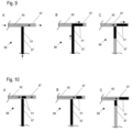
- FIG 10 shows a schematic view of T-shaped junctions 88 where droplets 23 of uniform volumes are generated.
- each droplet is sheared at both ends by using an alternating flow of two different liquids 60,61 at the T-shaped junction 88.
- the initial droplet which is generated from a bulk droplet at the shear location is sacrificed, so that the uncertainty of the position of the leading edge of the bulk droplet, which causes an uncertainty of the exact volume of the initial droplet generated, is removed.
- the flow directions of liquid 60,61 within the tube 87 are indicated by dashed arrows.
- a bulk droplet of processing liquid 61 is pumped into the T-shaped junction 88, and an initial volume of liquid 61 crosses the shear location.
- an initial droplet of processing liquid 61 is sheared of the bulk droplet at the shear point.
- the initial droplet of processing liquid 61 is discarded and may be pumped, for example by means of separate pump like a syringe pump 99, into a waste path for removal.
- the new leading edge of the bulk droplet of processing liquid 61 is now at a defined position within the T-shaped junction 88 (situation B), so that the following droplets may be generated under controlled conditions.
- the residual bulk droplet (situation C) is discarded as well to ensure that the last droplet is created by shearing on both ends.
- FIG 11 shows different views of a multi-port valve 89 which is configured for droplet generation independently from electrowetting processes in the cartridge 2.
- a number tubes 87 are connected for providing the carrier liquid 60 and/or different processing liquids 61 into the valve.
- a dashed arrow indicates in each situation A to E the direction of liquid flow in the tube 87 after droplet generation.
- Liquid flow may be controlled by a suction action of a syringe pump 99, for example, by the application of pressure using a syringe pump 99, or by other means for controlling the flow of liquids in a tubular system.
- the supply tubes 87 for the liquids are filled, and the carrier liquid 60, for example a silicone oil, is guided into the valve (situation A).
- the valve 89 is switched from oil to a processing liquid 61 (situation B), followed by switching back to the oil supply tube 87 (situation C), an alternating flow of carrier fluid 60 and processing fluid 61 is formed.
- FIG. 1 An example of moving liquid towards a waste removal processing is shown for the situations D and E.
- This process may be used when for example an air gap is located within the processing liquid 61 and the carrier liquid 60.
- reagents are pumped into the valve 89 with the air gap between the silicone oil and the processing liquid (situation D).
- the valve is switched to a tube 87 which is connected with the waste removal system, and the air is pumped to the waste removal processing place.
- Figure 12 shows a schematic view of an exemplary electrowetting sample processing system 1 comprising a multi-port valve 89 and a T-shaped junction 88 for droplet generation and another embodiment of tube arrangement and combination of elements for guiding liquids 60,61 into and from the cartridge 2.
- a multi-port valve 89 and a T-shaped junction 88 for droplet generation and another embodiment of tube arrangement and combination of elements for guiding liquids 60,61 into and from the cartridge 2.
- General details may be taken from the Figures 7 and 8 .
Landscapes
- Chemical & Material Sciences (AREA)
- Health & Medical Sciences (AREA)
- General Health & Medical Sciences (AREA)
- Dispersion Chemistry (AREA)
- Analytical Chemistry (AREA)
- Clinical Laboratory Science (AREA)
- Hematology (AREA)
- Chemical Kinetics & Catalysis (AREA)
- Biochemistry (AREA)
- General Physics & Mathematics (AREA)
- Immunology (AREA)
- Pathology (AREA)
- Life Sciences & Earth Sciences (AREA)
- Physics & Mathematics (AREA)
- Physical Or Chemical Processes And Apparatus (AREA)
- Automatic Analysis And Handling Materials Therefor (AREA)
Description
- The current invention relates to a cartridge, in particular a disposable cartridge for use in an electrowetting sample processing system, an electrowetting sample processing system, and a method for operating such a cartridge or system.
- The document
WO 2014/108186 A1 describes a cartridge with a waste zone, such that the cartridge together with the waste is discarded after process completion.US 2010/062508 A1 shows a droplet actuator with discrete and continuous flow sections separated by a barrier andUS 2015/144489 A1 concerns a self-containing disposable cartridge. - It is a task of the current invention to provide a cartridge that allows for a precise and versatile processing of microfluidic droplets.
- This task is solved by a cartridge with the features of
claim 1. Further embodiments of the cartridge, an electrowetting sample processing system with such a cartridge, as well as a method for operating such a cartridge or system are defined by the features of further claims. - A cartridge according to the invention, namely a cartridge for use in an electrowetting sample processing system, comprises one or more inlet ports for introducing an input liquid into an internal gap of the cartridge. The gap comprises at least one hydrophobic surface for enabling an electrowetting induced movement of multiple microfluidic droplets separated from the input liquid. The cartridge further comprises at least one outlet port that is operably connected to the inlet port for providing a liquid flow through the cartridge, if a liquid driving force, in particular an electrowetting force or a pressure force, is applied to at least a part of the input liquid. The cartridge comprises a first part with the inlet port and a second part attached to the first part, such that the gap is formed between the first part and the second part, the second part comprising an electrode support element or a flexible film.
- The cartridge comprises a first part with the inlet port and a second part attached to the first part, such that the gap is formed between the first part and the second part.
- The second part comprises an electrode support element or a flexible film.
- In a further embodiment, the first part comprises a rigid body and/or the second part comprises or is a polymer film. In particular, the second part is attached to a peripheral side structure of the first part.
- In a further embodiment, the gap is defined by a spacer that is arranged between the first part and the second part and/or by the shape of at least one of the two parts of the cartridge, in particular by a flexible part or a rigid part of the cartridge.
- In a further embodiment, one or more of the following comprise an outlet port: the first part, the second part, the spacer, the peripheral side structure of the first part.
- In a further embodiment, the cartridge is configured to provide the flow through the cartridge as a continuous flow and/or to substantially maintain a volume equilibrium in the cartridge. The continuous flow may include periods of unbalanced pressure, for example an under-pressure or an over-pressure, which may result from differences of flow between the input flow and the output flow, i.e. differences in the pumping characteristic. In one example, the maximum length of the period of unbalanced pressure is 1 second, in particular 0.25 seconds.
- In a further embodiment, the cartridge comprises a plurality of electrodes, in particular an electrode array, for applying an electrowetting force to the microfluidic droplets.
- In an embodiment, the second part of the cartridge, in particular the electrode support element or the flexible film or the membrane, is reversibly attachable to the electrodes of the electrowetting sample processing system.
- In a further embodiment, at least two of the electrodes are connected to an electrical interface, in particular to an electrical connector or contact field.
- In a further embodiment, the cartridge comprises the inlet port as a single inlet port.
- In a further embodiment, the cartridge is configured as a disposable cartridge and/or as cartridge that is removably attachable to an electrowetting sample processing system.
- In a further embodiment, the input liquid comprises a carrier liquid and/or an electrowetting filler liquid, further in particular a silicone oil.
- In a further embodiment, the input liquid comprises a processing liquid that comprises at least one of:
- a reagent,
- a buffer,
- a diluent,
- an extraction liquid,
- a washing liquid, and
- a suspension, which further in particular is a suspension of magnetic beads, single cells or cell aggregates.
- In a further embodiment, the cartridge comprises at least one liquid removal element, in particular a line removal and/or a removal zone, that is operably connected to the outlet port.
- In a further embodiment, the cartridge comprises a pressure compensation outlet and/or an air ventilation outlet for providing a fluid output arranged separate from the outlet port, in particular gas exhaust.
- The features of the above-mentioned embodiments of the cartridge can be used in any combination, unless they contradict each other.
- An electrowetting sample processing system according to the present invention, in particular a biological sample processing system, comprises a cartridge according to anyone of the above-mentioned embodiments.
- An electrowetting sample processing system according to the invention comprises a cartridge (2) with an internal gap and one or more inlet ports for introducing an input liquid into the internal gap. The gap comprises at least one hydrophobic surface for enabling an electrowetting induced movement of multiple microfluidic droplets separated from the input liquid. The internal gap further comprises at least one outlet port that is in operable connection with the inlet port for providing a liquid flow through the internal gap, if a liquid driving force, in particular an electrowetting force or a pressure force, is applied to at least a part of the input liquid. The cartridge comprises a first part with the inlet port and a second part attached to the first part, such that the gap is formed between the first part and the second part.
- In an embodiment, the electrowetting sample processing system comprises a plurality of electrodes for applying an electrowetting force to the microfluidic droplets, in particular an electrode array, further in particular a two-dimensional electrode array.
- In an embodiment, at least two of the electrodes are connected to an electrical interface, in particular to an electrical connector or contact field.
- In an embodiment, the electrowetting sample processing system comprises a cartridge, which is reversibly attachable to the electrodes of the electrowetting sample processing system, wherein in particular the cartridge comprises a electrode support element or a flexible second part, further in particular a flexible film or the membrane.
- In an embodiment, the electrowetting sample processing system or the cartridge comprises a processing zone, which is configured for processing samples, in particular for processing biological sample, and/or which is operably connected to the delivery zone.
- In an embodiment, the processing zone is configured for processing least one of:
- a chemical reaction,
- a washing process,
- a heating process,
- a mixing process,
- a dilution, and
- a hybridization.
- In an embodiment, the processing zone is configured for processing a PCR (Polymerase chain reaction) process and/or a hybridization.
- In an embodiment, the electrowetting sample processing system comprises a liquid feeder operably connected to the inlet port by a tube, in particular a flexible tube, for feeding the input liquid to the inlet port.
- In an embodiment, the liquid feeder is configured to provide the input liquid as sequential feed and/or alternating feed of a processing liquid and a carrier liquid.
- In an embodiment, the liquid feeder is configured to provide the input liquid as feed of at least two processing liquids of different compositions separated by an carrier liquid.
- In an embodiment, the liquid feeder comprises a T-shaped junction and/or a multi-port valve for providing the input liquid.
- In an embodiment, the liquid feeder comprises a bypass that is controllable for flushing a tube of the feeder and/or for removing an access liquid from a feeding liquid and to providing the remaining part of the feeding liquid as the input liquid.
- In an embodiment, the liquid feeder comprises a control element, in particular a pump and/or a multi-port valve, for introducing the input liquid into the internal gap and/or for removing an output liquid from the internal gap.
- In an embodiment, the liquid feeder is configured to operate independently and/or asynchronously from the operation of electrodes used for electrowetting.
- In an embodiment, the input liquid comprises at least one of:
- an electrowetting filler liquid, in particular a silicone oil,
- a carrier liquid, and
- a processing liquid, that in particular comprises at least one of:
- a reagent,
- a buffer,
- a diluent,
- an extraction liquid,
- a washing liquid, and
- a suspension, which further in particular is a suspension of magnetic beads, single cells or cell aggregates.
- In an embodiment, the electrowetting sample processing system comprises a reagent detector for indicating the presence of processing liquid in the input liquid and/or for monitoring the amount of processing liquid in the input liquid, in particular in relation to a predetermined value.
- The features of the above-mentioned embodiments of the electrowetting sample processing system can be used in any combination, unless they contradict each other.
- The invention further concerns a method for operating the cartridge according to the invention or the sample processing system according to the invention.
- The invention further concerns a method for operating a cartridge according to the invention or a sample processing system according to the invention that comprises an internal gap, which comprises one or more inlet ports, an outlet port and at least one hydrophobic surface enabling an electrowetting induced movement of microfluidic droplets separated from the input liquid. The method comprises:
- introducing an input liquid into an internal gap;
- providing a flow through the internal gap as a substantially continuous flow;
- transferring the liquid from the inlet port to the outlet port via the internal gap by applying a liquid driving force, in particular an electrowetting force or a pressure force, to at least a part of the input liquid; and
- removing the liquid from the internal gap (6) via the outlet port.
- In an embodiment, the driving force is provided by a plurality of electrodes, in particular by an electrode array, further in particular by a two-dimensional electrode array.
- In an embodiment, the step of providing the flow through the internal gap as a substantially continuous flow and/or maintaining a volume equilibrium.
- In an embodiment, the method comprises inducing a movement of multiple microfluidic droplets by operating a plurality of electrodes, in particular an electrode array (9), for applying the electrowetting force to the microfluidic droplets.
- In an embodiment, the input liquid comprises a carrier liquid and/or an electrowetting filler liquid, in particular a silicone oil. In a further embodiment, the input liquid comprises a processing liquid that comprises at least one of:
- a reagent,
- a buffer,
- a diluent,
- an extraction liquid,
- a washing liquid, and
- a suspension, which further in particular is a suspension of magnetic beads, single cells or cell aggregates.
- The features of the above-mentioned embodiments of the method can be used in any combination, unless they contradict each other.
- Embodiments of the current invention are described in more detail in the following with reference to the figures. These are for illustrative purposes only and are not to be construed as limiting. It shows
-
Fig. 1 an overview over an exemplary digital microfluidics system that is equipped with a central control unit and a base unit, with four cartridge accommodation sites and with four board accommodation sites for receiving an electrode board that each comprises an electrode array; -
Fig. 2 a section view of one cartridge accommodation site with a disposable cartridge according toFig. 1 ; the electrode array being located on a fixed bottom substrate; -
Fig. 3 a section view of a further exemplary cartridge accommodation site according toFig. 2 , wherein the electrode array is a part of the cartridge; -
Fig. 4 a section view of an exemplary cartridge accommodation site with a disposable cartridge according to a further embodiment accommodated therein; the cartridge comprising a flexible bottom layer; -
Fig. 5 a section view of an exemplary cartridge accommodation site with a disposable cartridge according to a further embodiment accommodated therein; also this cartridge comprising a flexible bottom layer; -
Fig. 6 a schematic view of an exemplary embodiment of an inlet port according to the invention; -
Fig. 7 a schematic overview over an exemplary embodiment of an electrowetting sample processing system with a cartridge, an inlet port and operably connected outlet ports; -
Fig. 8 a schematic overview over a further exemplary embodiment of an electrowetting sample processing system; -
Fig. 9 exemplarily in a schematic view how at a T-shaped junction a droplet of a processing liquid is formed; -
Fig. 10 a schematic view of a T-shaped junction, with which a high precision of a desired droplet volume may be achieved; -
Fig. 11 schematic views of multi-port valves for providing a predetermined volume of liquid droplets; and -
Fig. 12 a schematic view of an exemplary electrowetting sample processing system comprising a multi-port valve and a T-shaped junction for droplet generation. - The
Figure 1 shows an overview over an electrowetting sample processing system exemplary shown asdigital microfluidics system 1 that is equipped with acentral control unit 14 and abase unit 7, with fourcartridge accommodation sites 8 that each comprise anelectrode array 9, and acover plate 12. Thedigital microfluidics system 1 is configured for manipulating samples inliquid droplets 23 within cartridges designed asdisposable cartridges 2. Thisdigital microfluidics system 1 also comprises fourboard accommodation sites 40 for receiving anelectrode board 41. - The
digital microfluidics system 1 comprises abase unit 7 with at least onecartridge accommodation site 8 that is configured for taking up adisposable cartridge 2. Thedigital microfluidics system 1 can be a standalone and immobile unit, on which a number of operators are working withcartridges 2 that they bring along. Thedigital microfluidics system 1 thus may comprise a number ofcartridge accommodation sites 8 and a number ofelectrode arrays 9 at least some of which are located onelectrode boards 41. - It may be preferred to integrate the
digital microfluidics system 1 into a liquid handling workstation or into a Freedom EVO® robotic workstation, so that a pipetting robot can be utilized to transfer liquid portions and/or sample containing liquids to and from thecartridges 2. - Alternatively, the
system 1 can be can be configured as a hand-held unit which only comprises and is able to work with a low number, e.g. a singledisposable cartridge 2. Every person of skill will understand that intermediate solutions that are situated in-between the two extremes just mentioned will also operate and work within the gist of the present invention. - According to the present invention, the
digital microfluidics system 1 also comprises at least oneboard accommodation site 40 for taking up anelectrode board 41 which comprises anelectrode array 9 that substantially extends in a first plane and that comprises a number ofelectrodes 10. Such anelectrode board 41 preferably is located at each one of saidcartridge accommodation sites 8 of thebase unit 7. Preferably eachelectrode array 9 is supported by abottom substrate 11. It is noted that the expressions "electrode array", "electrode layout", and "printed circuit board (PCB)" are utilized herein as synonyms. - The
digital microfluidics system 1 may also comprise at least onecover plate 12 with a top substrate; though providing ofsuch cover plates 12 is particularly preferred, at least some of the cover plates may be dispensed with or may be re-placed by an alternative cover for holding adisposable cartridge 2 in place inside the base unit of themicrofluidics system 1. Thus, at least onecover plate 12 may be located at one of saidcartridge accommodation site 8. Thecover plate 12 and thebottom substrate 11 with theelectrode array 9 or PCB define a space orcartridge accommodation site 8 respectively. In a first variant (see the twocartridge accommodation sites 8 in the middle of thebase unit 7, thecartridge accommodation sites 8 are configured for receiving a slidingly inserteddisposable cartridge 2 that is movable in a direction substantially parallel with respect to theelectrode array 9 of the respective cartridgeaccommodating site 8. Such front- or top-loading can be supported by a drawing-in automatism that, following a partial insertion of adisposable cartridge 2, transports thecartridge 2 to its final destination within thecartridge accommodation site 8, where thecartridge 2 is precisely seated. Preferably, thesecartridge accommodation sites 8 do not comprise amovable cover plate 12. After carrying out all intended manipulations to the samples in liquid droplets, the usedcartridges 2 can be ejected by the drawingin automatism and transported to an analysis station or discarded. - In a second variant (see the two
cartridge accommodation sites 8 on the right and left of the base unit 7), thecartridge accommodation sites 8 comprise acover plate 12 that is configured to be movable with respect to theelectrode array 9 of the respective cartridgeaccommodating site 8. Thecover plate 12 preferably is configured to be movable about one or more hinges 16 and/or in a direction that is substantially normal to theelectrode array 9. - Similar to the possibilities for inserting a
disposable cartridge 2 into acartridge accommodation site 8, possibilities for inserting theelectrode board 41 into aboard accommodation site 40 comprise the following alternatives: - (a) vertically lowering the
electrode board 41 through the respectivecartridge accommodation site 8 and into theboard accommodation site 40; - (b) horizontally sliding the
electrode board 41 below the respectivecartridge accommodation site 8 and into theboard accommodation site 40; - (c) horizontally sliding the
electrode board 41 below the respectivecartridge accommodation site 8 and substantially vertically lifting into theboard accommodation site 40. - In
Fig. 1 , there is drawn only oneelectrode board 41 that slidingly can be inserted by front loading below the second cartridge accommodation site 8 (as counted from the left). All possible places for locating aboard accommodation site 40 are indicated and pointed to by dashed arrows. - The
digital microfluidics system 1 also comprises acentral control unit 14 for controlling the selection of theindividual electrodes 10 of said at least oneelectrode array 9 and for providing theseelectrodes 10 with individual voltage pulses for manipulating liquid droplets within saidcartridges 2 by electrowetting. As partly indicated inFig. 1 , everyelectrode 10 is operatively connected to thecentral control unit 14 and therefore can be independently or commonly addressed by thiscentral control unit 14, which also comprises the appropriate sources for creating and providing the necessary electrical potentials in a way known in the art. - The at least one
cover plate 12 preferably comprises an electrically conductive material that extends in a second plane and substantially parallel to theelectrode array 9 of thecartridge accommodation site 8 the at least onecover plate 12 is assigned to. It is particularly preferred that this electrically conductive material of thecover plate 12 is configured to be not connected to a source of an electrical ground potential. Thecover plate 12 can be configured to be movable in any arbitrary direction and no electrical contacts have to be taken in into consideration when selecting a particularly preferred movement of thecover plate 12. Thus, thecover plate 12 may be configured to be also movable in a direction substantially parallel to theelectrode array 9 and for carrying out a linear, circular or any arbitrary movement with respect to therespective electrode array 9 of thebase unit 7. - The
Figure 2 shows a section view of one exemplarycartridge accommodation site 8 with thedisposable cartridge 2 according toFig. 1 accommodated therein. Thedisposable cartridge 2 comprises abottom layer 3 as a second part of thecartridge 2, atop layer 4 as a first part of thecartridge 2, and aspacer 5 that defines a gap between the bottom andtop layers liquid droplets 23 in thisgap 6. - The
cover plate 12 is mechanically connected with thebase unit 7 of thedigital microfluidics system 1 via ahinge 16; thus, thecover plate 12 can swing open and adisposable cartridge 2 can be placed on thecartridge accommodation site 8 via top-entry loading (seeFig. 1 ). An electricallyconductive material 15 of thecover plate 12 is configured as a thin metal plate or metal foil that is attached to thetop substrate 13. Alternatively, the electricallyconductive material 15 of thecover plate 12 is configured as a metal layer that is deposited onto thetop substrate 13. Such deposition of theconductive material 15 may be carried out by chemical or physical vapor deposition techniques as they are known per se. - The
cover plate 12 is configured to apply a force to adisposable cartridge 2 that is accommodated at thecartridge accommodation site 8 of thebase unit 7. This force urges thedisposable cartridge 2 against theelectrode array 9 in order to position thebottom layer 3 of the cartridge as close as possible to the surface of theelectrode array 9. This force also urges thedisposable cartridge 2 into the perfect position on theelectrode array 9 with respect to an optional piercingfacility 18 of thecover plate 12. This piercingfacility 18 is configured for introducing sample droplets into thegap 6 of thecartridge 2. The piercingfacility 18 is configured as a throughhole 19 that leads across theentire cover plate 12 and that enables a piercingpipette tip 20 to be pushed through and pierce thetop layer 4 of thecartridge 2. The piercingpipette tip 20 may be a part of a handheld pipette (not shown) or of a pipetting robot (not shown). - In the case shown in
Fig. 2 , theelectrode array 9 is covered by adielectric layer 24. Theelectrode array 9 is fixed to abottom substrate 11, this combination is also called PCB, and everyindividual electrode 10 is electrically and operationally connected with the central control unit 14 (only three connections of the tenelectrodes 10 are drawn here). Alternatively, the electrodes may be commonly connected to an electrical interface, in particular to an electrical connector or an electrical contact field - which in turn is then electrically connected to acontrol unit 14. In one example, thebottom substrate 11 or the PCB that contains theelectrode array 9 or theelectrodes 10 has an electrical connector, which connects to a relay PCB, which is connected to a control PCB, wherein the control PCB is part of thecentral control unit 14. - The
electrode array 9 is located on an immovably fixedbottom substrate 11. Thedigital microfluidics system 1 is configured for manipulating samples inliquid droplets 23 withindisposable cartridges 2 that contain agap 6. Accordingly, the samples inliquid droplets 23 are manipulated in thegap 6 of thedisposable cartridge 2. Thedisposable cartridge 2 comprises thebottom layer 3, thetop layer 4, and thespacer 5 that defines thegap 6 between the bottom andtop layers liquid droplets 23 in thisgap 6. Thebottom layer 3 and thetop layer 4 comprise ahydrophobic surface 17 that is exposed to thegap 6 of thecartridge 2. Thebottom layer 3 and thetop layer 4 of thecartridge 2 are entirely hydrophobic films or at least comprise a hydrophobic surface that is exposed to thegap 6 of thecartridge 2. It is clear from thisFig. 2 , that thecartridge 2 does not have a conductive layer. Thespacer 5 of thecartridge 2 may optionally be configured as a body that includescompartments 21 for reagents needed in an assay that is applied to the sample droplets in the gap 6 (dotted lines). -
Figure 3 shows a section view of a further exemplary cartridge accommodation site according tofigure 2 with acartridge 2, wherein - in contrast tofigure 2 - thecartridge 2 comprises an electrode array 9' ofindividual electrodes 10. - Further the
cartridge 2 comprises anupper part 4, aspacer 5, a hydrophobic layer 3'', a support element 11' for the electrode array 9', an optional throughhole 19, a liquid input port 19' and electrically conductive material. Theupper part 4 and thespacer 5 may be provided as separate parts or in form of a single piece. The hydrophobic layer 3'', the electrode array 9' and the support element 11' form the lower part of the cartridge. The electrode array 9' is arranged between the hydrophobic layer 3'' and the support element 11' and the gap is formed between theupper part 4 and the hydrophobic layer 3''. Further, the hydrophobic layer 3'' is attached to a peripheral side structure of theupper part 4 resp. to thespacer 5. The support element 11' further comprises electrical connectors 14', which are connected via multiple electrical wires to the electrode array 9'. In turn, the electrical connectors 14' provide for a connection to acentral control unit 14 such that the electrical connectors 14' implement an electrical interface betweencartridge 2 and thedigital microfluidics system 1. The electrical interface can also be implemented by a contact field, i.e. a plurality of electrically conductive, mutually insulated contact areas. -
Figure 4 shows section view of onecartridge accommodation site 8 with adisposable cartridge 2 according to a further embodiment accommodated therein. Again, theelectrodes 10 are arranged on and fixed to thebottom substrate 11. Again, thedisposable cartridge 2 comprises a bottom layer 3' and atop layer 4. Attached to thedisposable cartridge 2 is aspacer 5 that defines agap 6 between the bottom andtop layer liquid droplets 23 in thisgap 6. In this embodiment, the bottom layer is a flexible bottom layer, for example a membrane 3', for example with ahydrophobic surface 17. For example, the membrane 3' is an 8 to 50 µm thick polypropylene film. The bottom layer 3' is arranged between thetop layer 4 and thespacer 5. - Preferably, the flexible
bottom layer 3 is reversibly attached to theelectrodes 10 in an electrowettingsample processing system 1. Thespacer 5 may be a part of thecartridge 2 or a part of the electrowettingsample processing system 1. In one example, thespacer 5 comprises stainless steel, aluminum, hard plastic, in particular COP or ceramic. Thespacer 5 may be designed to define the height of thegap 6. Thespacer 5 may additionally serve as a gasket for sealing thegap 6. - Preferred dimensions and materials are pointed to in table 1. These indications of materials and dimensions serve as preferred examples without limiting the scope of the present invention.
Table 1 Part No Material Dimensions and Shape Droplet 23 aqueous Volume: 0.1-5 µl Substrate 11 PCB; Synth. Polymer --- Electrodes 10 Al; Cu; Au; Pt Plating: 1.5 x 1.5 mm Film 3 Fluorinated ethylene propylene (FEP), Cyclo olefin polymer (COP), Polypropylene (PP) Thickness: 8-50 µm Hydrophobic surface 17 Teflon® (PTFE), COP, FEP, PP, Cytop Thickness: 8-50 µm Coating: 2-200 nm Spin coating: 5-500 nm, preferably 20 nm Rigid cover 4 Mylar®; acrylic; Polypropylene (PP) 65 x 85 mm; Plate: 0.5-25.0 mm, preferably 1.5 mm Gap 6 --- 0.2-2.0 mm, preferably 0.5 mm Pipetting orifice 19 --- Diameter: 0.3-3.0 mm Spacer, Gasket 5 Polypropylene (PP), Synthetic or natural rubber Frame: 0.2-2.0 mm, preferably 0.5 mm Electrowetting filler liquid Silicon oil Volume: 1-5 ml Carrier liquid for separating parts of processing liquid 60 e.g. Silicon oil Volume: 1-100 µl Processing liquid 61 Diverse, e.g. reagent liquid Volume: 1-100 µl - An inlet port 19' for introducing a liquid 60,61 into the
gap 6 is provided in thetop layer 4 of thecartridge 2. In addition, anoutlet port 80 is provided for removing liquid from thegap 6 of thecartridge 2. Theoutlet port 80 is arranged in this case also in thetop layer 4 of thecartridge 2. Preferably, thetop layer 4 comprises a rigid body when the inlet port 19' and/or anoutlet port 80 are arranged within thetop layer 4, to provide a certain stability to theports 19',80. Stability is desired to ensure a sufficiently tight connection oftubes 87 of an outer liquid circuit to the ports, so that the liquid does not leak at the connection between the port(s) 19',80 of thecartridge 2 and thetubes 87. - Preferably, the inlet port 19' and the
outlet port 80 are operably connected. By this, a liquid flow is provided through thecartridge 2 if a liquid driving force is applied to at least a part of theinput liquid 105. A liquid driving force may be a pressure force applied to at least a part of theinput liquid 105 and/or an electrowetting force for example applied to at least a part of theinput liquid 105 when it has been moved into thegap 6 of thecartridge 2. - In addition, a
vacuum supply line 92 is exemplarily shown inFigure 3 . By means of avacuum supply line 92, the bottom layer 3' may be attached tightly to the surface of theelectrodes 10. -
Figure 5 shows a section view of an exemplary cartridge accommodation site with a disposable cartridge according to a further embodiment accommodated therein. Also, thiscartridge 2 comprises a flexible bottom layer 3' which is arranged on theelectrodes 10. In this embodiment, thetop layer 4 comprisesperipheral side structures 82 which define thegap 6. For defining thegap 6, theperipheral side structures 82 are preferably rigid structures. The bottom layer 3' is attached to theperipheral side structures 82. Thus, in this embodiment shown, thegap 6 is defined by the shape and dimensions of thetop layer 4. It is possible to combine the use ofspacer 5 with the shape of thetop layer 4 or with a shape of thebottom layer 3 for defining thegap 6. - An inlet port 19' is provided again in the
top layer 4 of thecartridge 2. By means of the inlet port 19', aninput liquid cartridge 2. An inlet port 19' may also be arranged in the side structures of thecartridge 2, for example in aspacer 5 or inperipheral side structures 82 of thetop layer 4, depending on the chosen structure of thecartridge 2. In one example, the inlet port 19' is located on the bottom layer and enters thespacer 5 and - after a 90 degree turn - enters into the side of thecartridge 2. In another example the gap spacer that enables the liquid connection is located in the middle or a center part of thecartridge 2. - In the embodiment of
Figure 5 , twooutlet ports 80 are provided in the cartridge 2: oneoutlet port 80 is arranged in thetop layer 4, and oneoutlet port 80 is arranged in aperipheral side structure 82 of thetop layer 4. A certain degree of rigidity of thetop layer 4 and itsside structure 82 ensures a dimensionallystable gap 6 and also dimensionallystable ports 19',80. - The number of
outlet ports 80 provided by acartridge 2 may depend on the application for which thecartridge 2 is designed. According to the invention, at least one inlet port 19' and at least oneoutlet port 80 are provided, to enable a liquid flow throughout thecartridge 2. In another example multiple inlet ports 19' are used, which in particular provide input for different reagents or different classes of reagents, for example at least one bulk reagent via a first inlet port and at least one stoichiometric reagent via a second inlet port. In another example, the multiple inlet ports 19' are individually connected to a control element, in particular to amulti-port valve 90 and/or to a pump, to an individualinput syringe pump 99 and/or an individual T-shapedjunction 88. - In
Figure 5 , the inlet port 19' and one of theoutlet ports 80 comprise aseal 81. Such a seal may help to achieve a tight connection between thecartridge 2 and an "outer" liquid circuit or tubing system. -
Figure 6 shows a schematic view of an exemplary embodiment of an inlet port 19'. A first connectingsleeve 83 is arranged at the top of thetop layer 4. The first connectingsleeve 83 is formed integrally with thetop layer 4. The first connectingsleeve 83 comprises a centeringcone 94 at its inside, wherein the centeringcone 94 faces away from thetop layer 4 and widens with an increased distance to thetop layer 4. Asupply channel 50 is formed by atube 87 and a second connectingsleeve 84 with a centeringcone 95 at its inside. During the assembly, thetube 87 is centered by the centeringcone 94 of the first connectingsleeve 83. When completely inserted, thetube 87 forms a tight connection with the first connectingsleeve 83 and theseal 81 provided by the centeringsleeve 83. The centeringcone 95 of the second connectingsleeve 84 faces thetop layer 4 and widens with a reduced distance to thetop layer 4. The inside of the second connectingsleeve 84 is bigger than the outside of the first connectingsleeve 83. During the assembly, the second connectingsleeve 84 is centered by the outside of the first connectingsleeve 83. The free inner space in the inlet port 19' forms theinlet channel 19". - Alternatively, an inlet port 19' and/or an
outlet port 80 may be a simple passage opening into which a tube of an outer liquid circuit may be mounted. Preferably, the passage opening comprises aseal 81 for a tight connection. -
Figure 7 shows a schematic overview over an exemplary embodiment of an electrowettingsample processing system 1 with acartridge 2, an inlet port 19' and operably connected outlet ports. This particular embodiment comprises threedistinct outlet ports 80, with which liquid 60,61, may be removed from thecartridge 2. - By the operational connection of the inlet port 19' and the
outlet ports 80, a liquid flow through thecartridge 2 is provided, if a liquid driving force is applied to at least a part of theinput liquid 105. Theinput liquid 105 may comprise acarrier liquid 60 and/or aprocessing liquid 61. - A particular
suitable carrier liquid 60 is an electrowetting filler liquid, for example a silicone oil. In an embodiment, an additional carrier liquid, for example a silicone oil may be used. An electrowetting filler liquid may be used for filling thegap 6, while a carrier liquid may be used to a liquid which segments droplets in the droplet generator. In one embodiment, the electrowetting filler liquid and the carrier liquid may be the same liquid. In a further embodiment, the electrowetting filler liquid is a different liquid, for example a different oil than the liquid used as a carrier liquid. - A
processing liquid 61 can be any kind of liquid or liquid composition which is used for example in assay reactions or for analysis purposes or other applications carried out in thecartridge 2. Such aprocessing liquid 61 may be for example buffers, reaction liquids which comprise reactants required for a defined application, sample liquids which comprise a sample to be analyzed, diluent liquids, elution liquids, etc. Samples are for example DNA (Desoxyribonucleic acid), RNA (Ribonucleic Acid), derivatives thereof, proteins, cells, or other biologically or biochemically derived molecules or combinations thereof. Theprocessing liquid 61 may in an embodiment comprise magnetic beads, to which for example one or more samples are bound. - Applications which may be carried out using a
cartridge 2 and an electrowettingsample processing system 1 are for example at least one of chemical reactions, washing processes, heating processes, polymerase chain reaction (PCR) processes, hybridization processes, mixing processes, dilution processes, and NGS (next-generation sequencing) library prep assays. - The liquid flow through the
cartridge 2 is realized by removing an amount of liquid as anoutput liquid 102 from thecartridge 2 via theoutlet port 80 which is equivalent to the amount ofinput liquid 105 introduced into thecartridge 2. This operational linkage allows for example to maintain the level of liquid in thecartridge 2. Additionally, droplets of a determined volume may be generated outside thegap 6 of thecartridge 2, which allows a more precise volume control. This further allows storage of input liquids outside thecartridge 2, which removes requirements on the design of thegap 6 and the electrode array concerning for example the temperature of delicate liquids or volume requirements for bulk amounts of liquid. By removing such requirements from thecartridge 2, the design of the cartridge is more flexible, which allows the integration of more and/or more complex applications within onecartridge 2. Theoutput liquid 102 may comprise at least a part ofcarrier liquid 60, processingliquid 61, sample containing liquid or any combinations thereof. Theoutput liquid 102 may be treated as a waste liquid, which is discarded, or may be used for further processing. - Preferably, the delivery of the
input liquid 105 through a liquid inlet port 19' into thegap 6 for an electrowetting induced movement is synchronized with the electrowetting control, to ensure a proper hand-off ofdroplets 23. However, other processes outside thecartridge 2 required beforehand of the delivery may be carried out independently from the operations ofelectrodes 10 used for electrowetting. Though some processes may be synchronized, others may be carried out asynchronously from the operation of theelectrodes 10, as described in the following. - Possible liquid operations in connection with the liquid inlet port 19' and the outlet port(s) 80 are shown exemplarily in
Figure 7 : thecartridge 2 comprises one liquid inlet port 19' and threeoutlet ports 80 for liquids. Via the liquid inlet port 19',input liquid 105 may be introduced into theinternal gap 6 of thecartridge 2. Theinput liquid 105 is provided fromrespective storage tubes 98. Amulti-port valve 90 is in this case operably connected to thestorage tubes 98, and additionally to the liquid inlet port 19', directly or via further elements such as a T-shaped junction. The connection is realized here by atube 87 or a tube system comprisingmultiple tubes 87 that are in fluid connection to each other, so that theinput liquid 105 is fed into the inlet port 19' from the storage place into thecartridge 2. Preferably, thetube 87 is a flexible tube. - The
liquid feeder 86 comprises amulti-port valve 90 which allows for the movement ofliquids tubes 87 for introducing into theinternal gap 6 of thecartridge 2, wherein in particular, theliquid feeder 86 comprises a liquid selector valve, for example a multiport valve, that works with aninput syringe pump 99 for providing the liquid movement within the tubes. Because the inlet port 19' and theoutlet ports 80 are connected operationally, liquid may additionally be removed from thegap 6 of thecartridge 2 by means of a further pump or thewaste pump 103.Liquid cartridge 2 via theoutlet port 80 is transported viatubes 87 for example to a waste collecting place.Tubes 87 which are involved in the removal of waste liquids are shown in light grey, the direction of liquid movement within thetubes 87 is indicated by dashed arrows. - The movement of liquids within the
tubes 87 may be supported by providing one or more additional pumps 99,103 operably connected to the tube(s) 87, e.g. via abypass 97. In the embodiment of the electrowettingsample processing system 1 shown inFigure 6 , the removal of waste liquids is supported by the right one of the syringe pumps, which acts as anoutlet syringe pump 103 whereas the leftinput syringe pump 99 particularly supports the movement of theinput liquid 105. Waste liquids may then be collected in distinct waste collection containers, for example. - Waste management may further be supported by providing a
removal line 91 within thecartridge 2. Such aremoval line 91 is typically formed by a specific array of electrodes which guideinput liquid outlet port 80. This allows the immediate removal for example of wash fluid from the inlet port 19'. As shown inFigure 6 , aremoval zone 96, for example adjacent to theoutlet port 80, may additionally be provided for collecting waste droplets prior their removal from thecartridge 2. - The
liquid feeder 86 of the embodiment of the electrowettingsample processing system 1 shown inFigure 7 further comprises a T-shapedjunction 88 for providing a predetermined volume ofinput liquid liquid feeder 86 may comprises amulti-port valve 89 as shown for example inFigures 7 and11 . - At the T-shaped
junction 88 the cross-flow is used for generating droplets of a defined volume. In particular, ancarrier liquid 60 is pumped towards the T-shapedjunction 88 by theleft syringe pump 99 in alternating coordination with aprocessing liquid 61 from the direction of theliquid feeder 86, which is pumped into the T-shapedjunction 88 in a cross-flow direction. By alternating flows of processingliquid 61 andcarrier liquid 60, droplets of processingliquid 61 of controlled volume, separated by thecarrier liquid 60, are generated. - Two
different processing liquids 61 of a defined volume are generated by the T-shapedjunction 88, indicated by white and black droplets, and are transported towards the liquid inlet port 19'. The distinct volumes of processingliquid 61 are separated by specific volumes ofcarrier liquid 60, so that theprocessing liquids 61 may be fed to the inlet port 19' alternatingly with thecarrier liquid 60. Depending on the flow of thecarrier liquid 60 towards the T-shapedjunction 88 and the feeding ofdifferent processing liquids 61 into the tube towards thatjunction 88, it is also possible to provide theinput liquid 105 as a sequential feed of a single type ofprocessing liquid 61 or a sequential feed of two ormore processing liquids 61, which differ in their composition. - The
liquid feeder 86 comprises amulti-port valve 90 and fourseparate storage tubes 98, which are in fluid connection with themulti-port valve 90, wherein in eachstorage tube 98 stores adifferent processing liquid 61. In another example, up to 8, in particular up to 20,separate storage tubes 98 with different processing liquids are in fluid connection with themulti-port valve 90. Preferably, at least onestorage tube 98 is provided and connected to themulti-port valve 90, however,multiple storage tubes 98 are preferred to provide sufficient storage space fordifferent processing liquids 61. - In addition to the
processing liquid 61, thecarrier liquid 60 may be in fluid connection to the liquid feeder as well, as indicated for thesupply tube 87 on the rightmost side of themulti-port valve 90. - In the present embodiment, the
carrier liquid 60 comprises the same material composition as the electrowetting filler liquid, namely a silicon oil. In another example, thecarrier liquid 60 and theelectrowetting filler liquid 60 may be different, e.g. silicon oil with different viscosities. - The
liquid feeder 86 additionally comprises abypass 97 for removing access liquid from liquids which are to be provided asinput liquid 105. Other liquids such as liquids for flushing one ormore tubes 87 of theliquid feeder 86 may also be removed from the tubular connection with the inlet port 19' by using thebypass 87. - In this example, the
cartridge 2 further comprises anair ventilation outlet 85 for providing a fluid output that is arranged separate from the outlet port. Here, theair ventilation outlet 85 serves as gas exhaust, in another example, the pressure cartridge comprises a compensation outlet such as a liquid overflow. - In this embodiment, the electrowetting
sample processing system 1 comprises areagent detector 104 for indicating the presence of reagent liquid in the input liquid, for example by detecting at least one characteristic of the reagent liquid, in particular an optical characteristic such as transmissivity (resp. absorbance) or refraction index or an electrical characteristic such as resistance (resp. conductivity) or capacity. -
Figure 8 shows a schematic overview over another exemplary embodiment of an electrowettingsample processing system 1. The overall elements correspond to the elements as described inFigure 7 . The embodiment ofFigure 8 uses as a mechanism for storing and providing processing liquids areagent carousel 100 in combination with one ormore pipettes 101 for aspirating liquids from the storage place in thereagent carousel 100. Thereagent carousel 100 preferably comprises a rotation mechanism for positioning a desired storage place in relation to theaspiration pipette 101. Theaspiration pipette 101 is connected to thetube 87 for feeding the liquid inlet port 19' and may be configured to work automatically. For automatic aspiration of processingliquid 61, thepipette 101 may be configured to be movable at least along a Z-axis of a Cartesian coordinate system. -
Figure 9 shows exemplarily in a schematic view how at a T-shaped junction 88 a droplet of aprocessing liquid 61 is formed from a bulk droplet of that liquid, followed by a volume ofcarrier liquid 60. Flow directions ofliquid tube 87 are indicated by dashed arrows. A bulk droplet of aprocessing liquid 61 is moved for example by theinput syringe pump 99 and themulti-port valve 90 of theliquid feeder 86 forwards into the T-shapedjunction 88, while the flow of thecarrier liquid 61 is stopped (see situation in A and B). When the flow of thecarrier liquid 60 is started, this flow shears of an initial droplet of processing liquid 61 from the leading volume of the bulk droplet where the two fluid paths cross each other. A fluid path cross point as present in the T-shapedjunction 88 serves as a shear location (see situation C). The generated droplet may be pumped within thetube 87 towards the liquid inlet port 19', or into analternative tube 87, for example into thebypass 97. By repeating the alternating flow of processingliquid 61 andcarrier liquid 60 into the T-shapedjunction 88, a train of droplets of processingliquid 61 and intermediate liquid parts ofcarrier liquid 60 is generated, which may be fed to the liquid inlet port 19' of the cartridge. -
Figure 10 shows a schematic view of T-shapedjunctions 88 wheredroplets 23 of uniform volumes are generated. For this, each droplet is sheared at both ends by using an alternating flow of twodifferent liquids junction 88. The initial droplet which is generated from a bulk droplet at the shear location is sacrificed, so that the uncertainty of the position of the leading edge of the bulk droplet, which causes an uncertainty of the exact volume of the initial droplet generated, is removed. Again, the flow directions ofliquid tube 87 are indicated by dashed arrows. - As shown in situation A, a bulk droplet of processing
liquid 61 is pumped into the T-shapedjunction 88, and an initial volume ofliquid 61 crosses the shear location. By starting the flow of thecarrier liquid 60 towards the shear point in the T-shapedjunction 88, an initial droplet of processingliquid 61 is sheared of the bulk droplet at the shear point. The initial droplet of processingliquid 61 is discarded and may be pumped, for example by means of separate pump like asyringe pump 99, into a waste path for removal. The new leading edge of the bulk droplet of processingliquid 61 is now at a defined position within the T-shaped junction 88 (situation B), so that the following droplets may be generated under controlled conditions. The residual bulk droplet (situation C) is discarded as well to ensure that the last droplet is created by shearing on both ends. -
Figure 11 shows different views of amulti-port valve 89 which is configured for droplet generation independently from electrowetting processes in thecartridge 2. To themulti-port valve 89, anumber tubes 87 are connected for providing thecarrier liquid 60 and/ordifferent processing liquids 61 into the valve. A dashed arrow indicates in each situation A to E the direction of liquid flow in thetube 87 after droplet generation. Liquid flow may be controlled by a suction action of asyringe pump 99, for example, by the application of pressure using asyringe pump 99, or by other means for controlling the flow of liquids in a tubular system. For generating adroplet 23 of aprocessing liquid 61, which is embedded within acarrier liquid 60, thesupply tubes 87 for the liquids are filled, and thecarrier liquid 60, for example a silicone oil, is guided into the valve (situation A). Upon switching thevalve 89 from oil to a processing liquid 61 (situation B), followed by switching back to the oil supply tube 87 (situation C), an alternating flow ofcarrier fluid 60 andprocessing fluid 61 is formed. - An example of moving liquid towards a waste removal processing is shown for the situations D and E. This process may be used when for example an air gap is located within the
processing liquid 61 and thecarrier liquid 60. Using a syringe pump, reagents are pumped into thevalve 89 with the air gap between the silicone oil and the processing liquid (situation D). Then, the valve is switched to atube 87 which is connected with the waste removal system, and the air is pumped to the waste removal processing place. -
Figure 12 shows a schematic view of an exemplary electrowettingsample processing system 1 comprising amulti-port valve 89 and a T-shapedjunction 88 for droplet generation and another embodiment of tube arrangement and combination of elements for guidingliquids cartridge 2. General details may be taken from theFigures 7 and 8 .REFERENCE SIGNS LIST 1 electrowetting sample processing system digital microfluidics system 15 electrically conductive material 16 hinge 2 cartridge 17 hydrophobic surface 3 bottom layer 18 piercing facility 3' membrane 19 through hole 3'' hydrophobic layer 19' inlet port 19" channel 4 top layer 20 piercing pipette tip 5 spacer 21 compartment 6 gap between 3 and 4 22 additional piercing facility 7 base unit 8 cartridge accommodation site 23 liquid droplet 9,9' electrode array 24 dielectric layer 10 individual electrode 26 disposable pipette tip 27 piercing pin 11 bottom substrate 11' support element 40 board accommodation site 12 cover plate 41 electrode board 13 top substrate 50 supply channel 14 central control unit 60 carrier liquid 14' electrical connector 61 processing liquid 80 outlet port 81 seal 94 centering cone of first connection sleeve 82 peripheral side structure 83 first connecting sleeve 95 centering cone of second connection sleeve 84 second connecting sleeve 85 air ventilation outlet 96 removal zone 86 liquid feeder 97 bypass 87 tube 98 storage tube 88 T-shaped junction 99 input syringe pump 100 reagent carousel 89 multi-port valve 101 pipette 90 multi-port valve, pump 102 output liquid 91 removal line 103 output syringe pump 92 vacuum supply line 93 removal line 104 reagent detector 105 input liquid
Claims (15)
- A cartridge (2) for use in an electrowetting sample processing system, the cartridge comprising one or more inlet ports (19') for introducing an input liquid (105) into an internal gap (6) of the cartridge (2), which comprises at least one hydrophobic surface (17) for enabling an electrowetting induced movement of multiple microfluidic droplets (23) separated from the input liquid (105),wherein the cartridge (2) further comprises at least one outlet port (80) for removing liquid from the internal gap (6), wherein the at least one outlet port (80) is operably connected to the inlet port (19') for providing a continuous liquid flow through the internal gap (6), if a liquid driving force is applied to at least a part of the input liquid,characterized in that the cartridge (2) comprises a first part (4) with the inlet port (19') and a second part (3) attached to the first part (4), such that the gap (6) is formed between the first part (4) and the second part (3), the second part (3) comprising an electrode support element (11') or a flexible film (3').
- The cartridge (2) according to claim 1, wherein the first part (4) comprises a rigid body and/or the second part (3) comprises or is a polymer film, and wherein in particular the second part (4) is attached to a peripheral side structure (82) of the first part
- The cartridge (2) according to claim 1 or 2, wherein the gap (6) is defined by a spacer (5) that is arranged between the first part (4) and the second part (3,3') or by the shape of at least one of the two parts of the cartridge (2), in particular by a flexible part or a rigid part of the cartridge (2).
- The cartridge (2) according to anyone of the preceding claims, configured to substantially maintain a volume equilibrium in the cartridge (2).
- The cartridge (2) according to anyone of the preceding claims comprising a plurality of electrodes, in particular an electrode array (9), for applying an electrowetting force to the microfluidic droplets (23), wherein in particular at least two of the electrodes (10) are connected to an electrical interface (14'), in particular to an electrical connector or contact field.
- The cartridge (2) according to anyone of the preceding claims, configured as a disposable cartridge and/or as cartridge that is removably attachable to an electrowetting sample processing system (1).
- An electrowetting sample processing system (1) comprising a cartridge (2) according to anyone of the preceding claims.
- The electrowetting sample processing system (1) according to claim 7, comprising a plurality of electrodes (10) for applying an electrowetting force to the microfluidic droplets (23), in particular an electrode array (9;10), further in particular a two-dimensional electrode array.
- The electrowetting sample processing system (1) according to anyone of claims 7 to 8, comprising a liquid feeder (86) with a control element, the liquid feeder (86) being operably connected to the inlet port (19') by a tube (87) for feeding the input liquid (105) to the inlet port (19'), wherein in particular to the liquid feeder (86) at least one of the following applies:- is configured to provide the input liquid (105) as sequential feed and/or alternating feed of a processing liquid (61) and a carrier liquid (60)- is configured to provide the input liquid (105) as feed of at least two processing liquids (61) of different compositions separated by a carrier liquid (60), and- comprises a T-shaped junction (88) and/or a multi-port valve (89) for providing the input liquid.
- The electrowetting sample processing system (1) according to claim 9, wherein to the liquid feeder (86) at least one of the following applies:- comprises a bypass (97) that is controllable for flushing a tube of the feeder (86) and/or for removing an access liquid from a feeding liquid and to providing the remaining part of the feeding liquid as the input liquid (105),- comprises a control element, in particular a pump (99,103) or a multi-port valve (90), for introducing the input liquid (105) into the internal gap (6) and/or for removing an output liquid (102) from the internal gap (6), and- is configured to operate independently and/or asynchronously from the operation of electrodes (10) used for electrowetting.
- The electrowetting sample processing system (1) according to anyone of the claims 7 to 10, comprising a reagent detector (104) for indicating the presence of processing liquid in the input liquid (105) and/or for monitoring the amount of processing liquid in the input liquid (105), in particular in relation to a predetermined value.
- A method for operating a cartridge (2) that comprises a first part (4) with the inlet port (19') and a second part (3) attached to the first part (4), such that a gap (6) is formed between the first part (4) and the second part (3) and the second part (3) comprises an electrode support element (11') or a flexible film (3'), wherein the internal gap (6) comprises one or more inlet ports (19'), an outlet port (80) for removing liquid from the internal gap (6) of the cartridge (2) and at least one hydrophobic surface (17) for enabling an electrowetting induced movement of microfluidic droplets (23) separated from the input liquid, the method comprising:- introducing an input liquid (105) into an internal gap (6);- providing a flow through the internal gap (6) as a substantially continuous flow;- transferring the liquid from the inlet port (19') to the outlet port (80) via the internal gap (6) by applying a liquid driving force, in particular an electrowetting force or a pressure force, to at least a part of the input liquid (105); and- removing the liquid from the internal gap (6) via the outlet port (80).
- The method according to the claim 12, wherein the driving force is provided by a plurality of electrodes (10), in particular by an electrode array (9;10), further in particular by a two-dimensional electrode array.
- The method according to claim 12 or 13, wherein the method comprises:- the step of providing the flow through the internal gap (6) by maintaining a volume equilibrium, and/or- inducing a movement of multiple microfluidic droplets by operating a plurality of electrodes for applying the electrowetting force to the microfluidic droplets.
- The method according to anyone of the claims 12 to 14, wherein the input liquid (105) comprises a carrier liquid (60) and/or an electrowetting filler liquid, in particular a silicone oil and/or a processing liquid (61) that comprises at least one of:- a reagent,- a buffer,- a diluent,- an extraction liquid,- a washing liquid, and- a suspension, which further in particular is a suspension of magnetic beads, single cells or cell aggregates.
Applications Claiming Priority (1)
| Application Number | Priority Date | Filing Date | Title |
|---|---|---|---|
| PCT/EP2019/066935 WO2020259816A1 (en) | 2019-06-26 | 2019-06-26 | Cartridge, electrowetting sample processing system and feeding thereof |
Publications (2)
| Publication Number | Publication Date |
|---|---|
| EP3990178A1 EP3990178A1 (en) | 2022-05-04 |
| EP3990178B1 true EP3990178B1 (en) | 2025-05-21 |
Family
ID=67396906
Family Applications (1)
| Application Number | Title | Priority Date | Filing Date |
|---|---|---|---|
| EP19742527.5A Active EP3990178B1 (en) | 2019-06-26 | 2019-06-26 | Cartridge, electrowetting sample processing system and feeding thereof |
Country Status (3)
| Country | Link |
|---|---|
| EP (1) | EP3990178B1 (en) |
| CN (1) | CN114173925A (en) |
| WO (1) | WO2020259816A1 (en) |
Families Citing this family (1)
| Publication number | Priority date | Publication date | Assignee | Title |
|---|---|---|---|---|
| JP2022132968A (en) * | 2021-03-01 | 2022-09-13 | 株式会社サイダ・Fds | heat treatment equipment |
Family Cites Families (5)
| Publication number | Priority date | Publication date | Assignee | Title |
|---|---|---|---|---|
| US20040101444A1 (en) * | 2002-07-15 | 2004-05-27 | Xeotron Corporation | Apparatus and method for fluid delivery to a hybridization station |
| US20080085219A1 (en) * | 2006-10-05 | 2008-04-10 | Beebe David J | Microfluidic platform and method |
| EP2136920A2 (en) * | 2007-03-23 | 2009-12-30 | Advanced Liquid Logic, Inc. | Droplet actuator loading and target concentration |
| CN104994955B (en) | 2013-01-09 | 2017-09-26 | 泰肯贸易股份公司 | System for manipulating samples in droplets |
| JP6033959B2 (en) * | 2013-01-09 | 2016-11-30 | テカン・トレーディング・アクチェンゲゼルシャフトTECAN Trading AG | Disposable cartridge for microfluidic system |
-
2019
- 2019-06-26 EP EP19742527.5A patent/EP3990178B1/en active Active
- 2019-06-26 WO PCT/EP2019/066935 patent/WO2020259816A1/en not_active Ceased
- 2019-06-26 CN CN201980098871.2A patent/CN114173925A/en active Pending
Also Published As
| Publication number | Publication date |
|---|---|
| CN114173925A (en) | 2022-03-11 |
| EP3990178A1 (en) | 2022-05-04 |
| WO2020259816A1 (en) | 2020-12-30 |
Similar Documents
| Publication | Publication Date | Title |
|---|---|---|
| EP2999538B1 (en) | Digital microfluidics system with swappable pcb`s | |
| US10724988B2 (en) | Digital microfluidics system with swappable PCB's | |
| US8821705B2 (en) | Digital microfluidics system with disposable cartridges | |
| EP2869922B1 (en) | Disposable cartridge for microfluidics systems | |
| US11951482B2 (en) | Cartridge and electrowetting sample processing system with delivery zone | |
| CN108139418B (en) | Subject processing chip, subject processing apparatus, and subject processing method | |
| US20030230488A1 (en) | Microfluidic device preparation system | |
| US12115532B2 (en) | Cartridge, electrowetting sample processing system and bead manipulation method | |
| US20240118239A1 (en) | Cartridge, Electrowetting Sample Processing System and Feeding Thereof | |
| EP3990178A1 (en) | Cartridge, electrowetting sample processing system and feeding thereof | |
| US11933760B2 (en) | Cartridge, electrowetting sample processing system and droplet formation | |
| EP3990177B1 (en) | Cartridge and electrowetting sample processing system with delivery zone, and associated method | |
| EP4347099B1 (en) | Mixing liquids using an automated liquid handling system | |
| EP3956061A1 (en) | Cartridge, electrowetting sample processing system and droplet formation |
Legal Events
| Date | Code | Title | Description |
|---|---|---|---|
| STAA | Information on the status of an ep patent application or granted ep patent |
Free format text: STATUS: UNKNOWN |
|
| STAA | Information on the status of an ep patent application or granted ep patent |
Free format text: STATUS: THE INTERNATIONAL PUBLICATION HAS BEEN MADE |
|
| PUAI | Public reference made under article 153(3) epc to a published international application that has entered the european phase |
Free format text: ORIGINAL CODE: 0009012 |
|
| STAA | Information on the status of an ep patent application or granted ep patent |
Free format text: STATUS: REQUEST FOR EXAMINATION WAS MADE |
|
| 17P | Request for examination filed |
Effective date: 20211118 |
|
| AK | Designated contracting states |
Kind code of ref document: A1 Designated state(s): AL AT BE BG CH CY CZ DE DK EE ES FI FR GB GR HR HU IE IS IT LI LT LU LV MC MK MT NL NO PL PT RO RS SE SI SK SM TR |
|
| DAV | Request for validation of the european patent (deleted) | ||
| DAX | Request for extension of the european patent (deleted) | ||
| STAA | Information on the status of an ep patent application or granted ep patent |
Free format text: STATUS: EXAMINATION IS IN PROGRESS |
|
| 17Q | First examination report despatched |
Effective date: 20221006 |
|
| P01 | Opt-out of the competence of the unified patent court (upc) registered |
Effective date: 20230522 |
|
| GRAP | Despatch of communication of intention to grant a patent |
Free format text: ORIGINAL CODE: EPIDOSNIGR1 |
|
| STAA | Information on the status of an ep patent application or granted ep patent |
Free format text: STATUS: GRANT OF PATENT IS INTENDED |
|
| INTG | Intention to grant announced |
Effective date: 20241212 |
|
| GRAS | Grant fee paid |
Free format text: ORIGINAL CODE: EPIDOSNIGR3 |
|
| GRAA | (expected) grant |
Free format text: ORIGINAL CODE: 0009210 |
|
| STAA | Information on the status of an ep patent application or granted ep patent |
Free format text: STATUS: THE PATENT HAS BEEN GRANTED |
|
| AK | Designated contracting states |
Kind code of ref document: B1 Designated state(s): AL AT BE BG CH CY CZ DE DK EE ES FI FR GB GR HR HU IE IS IT LI LT LU LV MC MK MT NL NO PL PT RO RS SE SI SK SM TR |
|
| REG | Reference to a national code |
Ref country code: GB Ref legal event code: FG4D |
|
| REG | Reference to a national code |
Ref country code: CH Ref legal event code: EP |
|
| REG | Reference to a national code |
Ref country code: DE Ref legal event code: R096 Ref document number: 602019070236 Country of ref document: DE |
|
| REG | Reference to a national code |
Ref country code: IE Ref legal event code: FG4D |
|
| PGFP | Annual fee paid to national office [announced via postgrant information from national office to epo] |
Ref country code: DE Payment date: 20250611 Year of fee payment: 7 |
|
| PGFP | Annual fee paid to national office [announced via postgrant information from national office to epo] |
Ref country code: GB Payment date: 20250612 Year of fee payment: 7 |
|
| PGFP | Annual fee paid to national office [announced via postgrant information from national office to epo] |
Ref country code: FR Payment date: 20250610 Year of fee payment: 7 |
|
| REG | Reference to a national code |
Ref country code: NL Ref legal event code: MP Effective date: 20250521 |
|
| PG25 | Lapsed in a contracting state [announced via postgrant information from national office to epo] |
Ref country code: PT Free format text: LAPSE BECAUSE OF FAILURE TO SUBMIT A TRANSLATION OF THE DESCRIPTION OR TO PAY THE FEE WITHIN THE PRESCRIBED TIME-LIMIT Effective date: 20250922 Ref country code: ES Free format text: LAPSE BECAUSE OF FAILURE TO SUBMIT A TRANSLATION OF THE DESCRIPTION OR TO PAY THE FEE WITHIN THE PRESCRIBED TIME-LIMIT Effective date: 20250521 Ref country code: FI Free format text: LAPSE BECAUSE OF FAILURE TO SUBMIT A TRANSLATION OF THE DESCRIPTION OR TO PAY THE FEE WITHIN THE PRESCRIBED TIME-LIMIT Effective date: 20250521 |
|
| REG | Reference to a national code |
Ref country code: LT Ref legal event code: MG9D |
|
| PG25 | Lapsed in a contracting state [announced via postgrant information from national office to epo] |
Ref country code: NO Free format text: LAPSE BECAUSE OF FAILURE TO SUBMIT A TRANSLATION OF THE DESCRIPTION OR TO PAY THE FEE WITHIN THE PRESCRIBED TIME-LIMIT Effective date: 20250821 Ref country code: GR Free format text: LAPSE BECAUSE OF FAILURE TO SUBMIT A TRANSLATION OF THE DESCRIPTION OR TO PAY THE FEE WITHIN THE PRESCRIBED TIME-LIMIT Effective date: 20250822 |
|
| PG25 | Lapsed in a contracting state [announced via postgrant information from national office to epo] |
Ref country code: NL Free format text: LAPSE BECAUSE OF FAILURE TO SUBMIT A TRANSLATION OF THE DESCRIPTION OR TO PAY THE FEE WITHIN THE PRESCRIBED TIME-LIMIT Effective date: 20250521 Ref country code: PL Free format text: LAPSE BECAUSE OF FAILURE TO SUBMIT A TRANSLATION OF THE DESCRIPTION OR TO PAY THE FEE WITHIN THE PRESCRIBED TIME-LIMIT Effective date: 20250521 |
|
| PG25 | Lapsed in a contracting state [announced via postgrant information from national office to epo] |
Ref country code: BG Free format text: LAPSE BECAUSE OF FAILURE TO SUBMIT A TRANSLATION OF THE DESCRIPTION OR TO PAY THE FEE WITHIN THE PRESCRIBED TIME-LIMIT Effective date: 20250521 |
|
| PG25 | Lapsed in a contracting state [announced via postgrant information from national office to epo] |
Ref country code: HR Free format text: LAPSE BECAUSE OF FAILURE TO SUBMIT A TRANSLATION OF THE DESCRIPTION OR TO PAY THE FEE WITHIN THE PRESCRIBED TIME-LIMIT Effective date: 20250521 |
|
| PGFP | Annual fee paid to national office [announced via postgrant information from national office to epo] |
Ref country code: CH Payment date: 20250701 Year of fee payment: 7 |
|
| PG25 | Lapsed in a contracting state [announced via postgrant information from national office to epo] |
Ref country code: RS Free format text: LAPSE BECAUSE OF FAILURE TO SUBMIT A TRANSLATION OF THE DESCRIPTION OR TO PAY THE FEE WITHIN THE PRESCRIBED TIME-LIMIT Effective date: 20250821 |
|
| PG25 | Lapsed in a contracting state [announced via postgrant information from national office to epo] |
Ref country code: IS Free format text: LAPSE BECAUSE OF FAILURE TO SUBMIT A TRANSLATION OF THE DESCRIPTION OR TO PAY THE FEE WITHIN THE PRESCRIBED TIME-LIMIT Effective date: 20250921 |
|
| PG25 | Lapsed in a contracting state [announced via postgrant information from national office to epo] |
Ref country code: LV Free format text: LAPSE BECAUSE OF FAILURE TO SUBMIT A TRANSLATION OF THE DESCRIPTION OR TO PAY THE FEE WITHIN THE PRESCRIBED TIME-LIMIT Effective date: 20250521 |
|
| REG | Reference to a national code |
Ref country code: AT Ref legal event code: MK05 Ref document number: 1796339 Country of ref document: AT Kind code of ref document: T Effective date: 20250521 |
|
| PG25 | Lapsed in a contracting state [announced via postgrant information from national office to epo] |
Ref country code: AT Free format text: LAPSE BECAUSE OF FAILURE TO SUBMIT A TRANSLATION OF THE DESCRIPTION OR TO PAY THE FEE WITHIN THE PRESCRIBED TIME-LIMIT Effective date: 20250521 Ref country code: DK Free format text: LAPSE BECAUSE OF FAILURE TO SUBMIT A TRANSLATION OF THE DESCRIPTION OR TO PAY THE FEE WITHIN THE PRESCRIBED TIME-LIMIT Effective date: 20250521 Ref country code: SM Free format text: LAPSE BECAUSE OF FAILURE TO SUBMIT A TRANSLATION OF THE DESCRIPTION OR TO PAY THE FEE WITHIN THE PRESCRIBED TIME-LIMIT Effective date: 20250521 |
|
| PG25 | Lapsed in a contracting state [announced via postgrant information from national office to epo] |
Ref country code: CZ Free format text: LAPSE BECAUSE OF FAILURE TO SUBMIT A TRANSLATION OF THE DESCRIPTION OR TO PAY THE FEE WITHIN THE PRESCRIBED TIME-LIMIT Effective date: 20250521 |
|
| PG25 | Lapsed in a contracting state [announced via postgrant information from national office to epo] |
Ref country code: EE Free format text: LAPSE BECAUSE OF FAILURE TO SUBMIT A TRANSLATION OF THE DESCRIPTION OR TO PAY THE FEE WITHIN THE PRESCRIBED TIME-LIMIT Effective date: 20250521 |
|
| PG25 | Lapsed in a contracting state [announced via postgrant information from national office to epo] |
Ref country code: SK Free format text: LAPSE BECAUSE OF FAILURE TO SUBMIT A TRANSLATION OF THE DESCRIPTION OR TO PAY THE FEE WITHIN THE PRESCRIBED TIME-LIMIT Effective date: 20250521 Ref country code: RO Free format text: LAPSE BECAUSE OF FAILURE TO SUBMIT A TRANSLATION OF THE DESCRIPTION OR TO PAY THE FEE WITHIN THE PRESCRIBED TIME-LIMIT Effective date: 20250521 |
|
| PG25 | Lapsed in a contracting state [announced via postgrant information from national office to epo] |
Ref country code: IT Free format text: LAPSE BECAUSE OF FAILURE TO SUBMIT A TRANSLATION OF THE DESCRIPTION OR TO PAY THE FEE WITHIN THE PRESCRIBED TIME-LIMIT Effective date: 20250521 |
|
| PG25 | Lapsed in a contracting state [announced via postgrant information from national office to epo] |
Ref country code: LU Free format text: LAPSE BECAUSE OF NON-PAYMENT OF DUE FEES Effective date: 20250626 |
|
| PG25 | Lapsed in a contracting state [announced via postgrant information from national office to epo] |
Ref country code: MC Free format text: LAPSE BECAUSE OF FAILURE TO SUBMIT A TRANSLATION OF THE DESCRIPTION OR TO PAY THE FEE WITHIN THE PRESCRIBED TIME-LIMIT Effective date: 20250521 |
|
| REG | Reference to a national code |
Ref country code: DE Ref legal event code: R097 Ref document number: 602019070236 Country of ref document: DE |
|
| REG | Reference to a national code |
Ref country code: BE Ref legal event code: MM Effective date: 20250630 |
|
| PLBE | No opposition filed within time limit |
Free format text: ORIGINAL CODE: 0009261 |
|
| STAA | Information on the status of an ep patent application or granted ep patent |
Free format text: STATUS: NO OPPOSITION FILED WITHIN TIME LIMIT |
|
| REG | Reference to a national code |
Ref country code: CH Ref legal event code: L10 Free format text: ST27 STATUS EVENT CODE: U-0-0-L10-L00 (AS PROVIDED BY THE NATIONAL OFFICE) Effective date: 20260402 |
|
| PG25 | Lapsed in a contracting state [announced via postgrant information from national office to epo] |
Ref country code: IE Free format text: LAPSE BECAUSE OF NON-PAYMENT OF DUE FEES Effective date: 20250626 |
|
| PG25 | Lapsed in a contracting state [announced via postgrant information from national office to epo] |
Ref country code: BE Free format text: LAPSE BECAUSE OF NON-PAYMENT OF DUE FEES Effective date: 20250630 |
|
| 26N | No opposition filed |
Effective date: 20260224 |