EP3989677A1 - Additively manufactured heater - Google Patents
Additively manufactured heater Download PDFInfo
- Publication number
- EP3989677A1 EP3989677A1 EP21203409.4A EP21203409A EP3989677A1 EP 3989677 A1 EP3989677 A1 EP 3989677A1 EP 21203409 A EP21203409 A EP 21203409A EP 3989677 A1 EP3989677 A1 EP 3989677A1
- Authority
- EP
- European Patent Office
- Prior art keywords
- heater
- dielectric material
- heating zone
- wire
- heater wire
- Prior art date
- Legal status (The legal status is an assumption and is not a legal conclusion. Google has not performed a legal analysis and makes no representation as to the accuracy of the status listed.)
- Granted
Links
Images


Classifications
-
- H—ELECTRICITY
- H05—ELECTRIC TECHNIQUES NOT OTHERWISE PROVIDED FOR
- H05B—ELECTRIC HEATING; ELECTRIC LIGHT SOURCES NOT OTHERWISE PROVIDED FOR; CIRCUIT ARRANGEMENTS FOR ELECTRIC LIGHT SOURCES, IN GENERAL
- H05B3/00—Ohmic-resistance heating
- H05B3/20—Heating elements having extended surface area substantially in a two-dimensional [2D] plane, e.g. plate-heater
-
- B—PERFORMING OPERATIONS; TRANSPORTING
- B29—WORKING OF PLASTICS; WORKING OF SUBSTANCES IN A PLASTIC STATE IN GENERAL
- B29C—SHAPING OR JOINING OF PLASTICS; SHAPING OF MATERIAL IN A PLASTIC STATE, NOT OTHERWISE PROVIDED FOR; AFTER-TREATMENT OF THE SHAPED PRODUCTS, e.g. REPAIRING
- B29C64/00—Additive manufacturing, i.e. manufacturing of three-dimensional [3D] objects by additive deposition, additive agglomeration or additive layering, e.g. by 3D printing, stereolithography or selective laser sintering
- B29C64/10—Processes of additive manufacturing
- B29C64/106—Processes of additive manufacturing using only liquids or viscous materials, e.g. depositing a continuous bead of viscous material
- B29C64/118—Processes of additive manufacturing using only liquids or viscous materials, e.g. depositing a continuous bead of viscous material using filamentary material being melted, e.g. fused deposition modelling [FDM]
-
- B—PERFORMING OPERATIONS; TRANSPORTING
- B29—WORKING OF PLASTICS; WORKING OF SUBSTANCES IN A PLASTIC STATE IN GENERAL
- B29C—SHAPING OR JOINING OF PLASTICS; SHAPING OF MATERIAL IN A PLASTIC STATE, NOT OTHERWISE PROVIDED FOR; AFTER-TREATMENT OF THE SHAPED PRODUCTS, e.g. REPAIRING
- B29C64/00—Additive manufacturing, i.e. manufacturing of three-dimensional [3D] objects by additive deposition, additive agglomeration or additive layering, e.g. by 3D printing, stereolithography or selective laser sintering
- B29C64/20—Apparatus for additive manufacturing; Details thereof or accessories therefor
- B29C64/205—Means for applying layers
- B29C64/209—Heads; Nozzles
-
- B—PERFORMING OPERATIONS; TRANSPORTING
- B33—ADDITIVE MANUFACTURING TECHNOLOGY
- B33Y—ADDITIVE MANUFACTURING, i.e. MANUFACTURING OF THREE-DIMENSIONAL [3D] OBJECTS BY ADDITIVE DEPOSITION, ADDITIVE AGGLOMERATION OR ADDITIVE LAYERING, e.g. BY 3D PRINTING, STEREOLITHOGRAPHY OR SELECTIVE LASER SINTERING
- B33Y10/00—Processes of additive manufacturing
-
- B—PERFORMING OPERATIONS; TRANSPORTING
- B33—ADDITIVE MANUFACTURING TECHNOLOGY
- B33Y—ADDITIVE MANUFACTURING, i.e. MANUFACTURING OF THREE-DIMENSIONAL [3D] OBJECTS BY ADDITIVE DEPOSITION, ADDITIVE AGGLOMERATION OR ADDITIVE LAYERING, e.g. BY 3D PRINTING, STEREOLITHOGRAPHY OR SELECTIVE LASER SINTERING
- B33Y30/00—Apparatus for additive manufacturing; Details thereof or accessories therefor
-
- B—PERFORMING OPERATIONS; TRANSPORTING
- B33—ADDITIVE MANUFACTURING TECHNOLOGY
- B33Y—ADDITIVE MANUFACTURING, i.e. MANUFACTURING OF THREE-DIMENSIONAL [3D] OBJECTS BY ADDITIVE DEPOSITION, ADDITIVE AGGLOMERATION OR ADDITIVE LAYERING, e.g. BY 3D PRINTING, STEREOLITHOGRAPHY OR SELECTIVE LASER SINTERING
- B33Y70/00—Materials specially adapted for additive manufacturing
- B33Y70/10—Composites of different types of material, e.g. mixtures of ceramics and polymers or mixtures of metals and biomaterials
-
- B—PERFORMING OPERATIONS; TRANSPORTING
- B33—ADDITIVE MANUFACTURING TECHNOLOGY
- B33Y—ADDITIVE MANUFACTURING, i.e. MANUFACTURING OF THREE-DIMENSIONAL [3D] OBJECTS BY ADDITIVE DEPOSITION, ADDITIVE AGGLOMERATION OR ADDITIVE LAYERING, e.g. BY 3D PRINTING, STEREOLITHOGRAPHY OR SELECTIVE LASER SINTERING
- B33Y80/00—Products made by additive manufacturing
-
- B—PERFORMING OPERATIONS; TRANSPORTING
- B64—AIRCRAFT; AVIATION; COSMONAUTICS
- B64D—EQUIPMENT FOR FITTING IN OR TO AIRCRAFT; FLIGHT SUITS; PARACHUTES; ARRANGEMENT OR MOUNTING OF POWER PLANTS OR PROPULSION TRANSMISSIONS IN AIRCRAFT
- B64D15/00—De-icing or preventing icing on exterior surfaces of aircraft
- B64D15/12—De-icing or preventing icing on exterior surfaces of aircraft by electric heating
-
- G—PHYSICS
- G01—MEASURING; TESTING
- G01P—MEASURING LINEAR OR ANGULAR SPEED, ACCELERATION, DECELERATION, OR SHOCK; INDICATING PRESENCE, ABSENCE, OR DIRECTION, OF MOVEMENT
- G01P5/00—Measuring speed of fluids, e.g. of air stream; Measuring speed of bodies relative to fluids, e.g. of ship, of aircraft
- G01P5/14—Measuring speed of fluids, e.g. of air stream; Measuring speed of bodies relative to fluids, e.g. of ship, of aircraft by measuring differences of pressure in the fluid
- G01P5/16—Measuring speed of fluids, e.g. of air stream; Measuring speed of bodies relative to fluids, e.g. of ship, of aircraft by measuring differences of pressure in the fluid using Pitot tubes, e.g. Machmeter
- G01P5/165—Arrangements or constructions of Pitot tubes
-
- H—ELECTRICITY
- H05—ELECTRIC TECHNIQUES NOT OTHERWISE PROVIDED FOR
- H05B—ELECTRIC HEATING; ELECTRIC LIGHT SOURCES NOT OTHERWISE PROVIDED FOR; CIRCUIT ARRANGEMENTS FOR ELECTRIC LIGHT SOURCES, IN GENERAL
- H05B3/00—Ohmic-resistance heating
- H05B3/10—Heating elements characterised by the composition or nature of the materials or by the arrangement of the conductor
- H05B3/18—Heating elements characterised by the composition or nature of the materials or by the arrangement of the conductor the conductor being embedded in an insulating material
-
- B—PERFORMING OPERATIONS; TRANSPORTING
- B29—WORKING OF PLASTICS; WORKING OF SUBSTANCES IN A PLASTIC STATE IN GENERAL
- B29K—INDEXING SCHEME ASSOCIATED WITH SUBCLASSES B29B, B29C OR B29D, RELATING TO MOULDING MATERIALS OR TO MATERIALS FOR MOULDS, REINFORCEMENTS, FILLERS OR PREFORMED PARTS, e.g. INSERTS
- B29K2101/00—Use of unspecified macromolecular compounds as moulding material
- B29K2101/12—Thermoplastic materials
-
- B—PERFORMING OPERATIONS; TRANSPORTING
- B29—WORKING OF PLASTICS; WORKING OF SUBSTANCES IN A PLASTIC STATE IN GENERAL
- B29K—INDEXING SCHEME ASSOCIATED WITH SUBCLASSES B29B, B29C OR B29D, RELATING TO MOULDING MATERIALS OR TO MATERIALS FOR MOULDS, REINFORCEMENTS, FILLERS OR PREFORMED PARTS, e.g. INSERTS
- B29K2305/00—Use of metals, their alloys or their compounds, as reinforcement
- B29K2305/08—Transition metals
-
- B—PERFORMING OPERATIONS; TRANSPORTING
- B29—WORKING OF PLASTICS; WORKING OF SUBSTANCES IN A PLASTIC STATE IN GENERAL
- B29L—INDEXING SCHEME ASSOCIATED WITH SUBCLASS B29C, RELATING TO PARTICULAR ARTICLES
- B29L2031/00—Other particular articles
- B29L2031/779—Heating equipment
-
- H—ELECTRICITY
- H05—ELECTRIC TECHNIQUES NOT OTHERWISE PROVIDED FOR
- H05B—ELECTRIC HEATING; ELECTRIC LIGHT SOURCES NOT OTHERWISE PROVIDED FOR; CIRCUIT ARRANGEMENTS FOR ELECTRIC LIGHT SOURCES, IN GENERAL
- H05B2203/00—Aspects relating to Ohmic resistive heating covered by group H05B3/00
- H05B2203/014—Heaters using resistive wires or cables not provided for in H05B3/54
-
- H—ELECTRICITY
- H05—ELECTRIC TECHNIQUES NOT OTHERWISE PROVIDED FOR
- H05B—ELECTRIC HEATING; ELECTRIC LIGHT SOURCES NOT OTHERWISE PROVIDED FOR; CIRCUIT ARRANGEMENTS FOR ELECTRIC LIGHT SOURCES, IN GENERAL
- H05B2203/00—Aspects relating to Ohmic resistive heating covered by group H05B3/00
- H05B2203/016—Heaters using particular connecting means
-
- H—ELECTRICITY
- H05—ELECTRIC TECHNIQUES NOT OTHERWISE PROVIDED FOR
- H05B—ELECTRIC HEATING; ELECTRIC LIGHT SOURCES NOT OTHERWISE PROVIDED FOR; CIRCUIT ARRANGEMENTS FOR ELECTRIC LIGHT SOURCES, IN GENERAL
- H05B2203/00—Aspects relating to Ohmic resistive heating covered by group H05B3/00
- H05B2203/017—Manufacturing methods or apparatus for heaters
-
- H—ELECTRICITY
- H05—ELECTRIC TECHNIQUES NOT OTHERWISE PROVIDED FOR
- H05B—ELECTRIC HEATING; ELECTRIC LIGHT SOURCES NOT OTHERWISE PROVIDED FOR; CIRCUIT ARRANGEMENTS FOR ELECTRIC LIGHT SOURCES, IN GENERAL
- H05B2203/00—Aspects relating to Ohmic resistive heating covered by group H05B3/00
- H05B2203/037—Heaters with zones of different power density
-
- H—ELECTRICITY
- H05—ELECTRIC TECHNIQUES NOT OTHERWISE PROVIDED FOR
- H05B—ELECTRIC HEATING; ELECTRIC LIGHT SOURCES NOT OTHERWISE PROVIDED FOR; CIRCUIT ARRANGEMENTS FOR ELECTRIC LIGHT SOURCES, IN GENERAL
- H05B2214/00—Aspects relating to resistive heating, induction heating and heating using microwaves, covered by groups H05B3/00, H05B6/00
- H05B2214/02—Heaters specially designed for de-icing or protection against icing
Definitions
- the system of the preceding paragraph can optionally include, additionally and/or alternatively, any one or more of the following features, configurations and/or additional components:
Landscapes
- Engineering & Computer Science (AREA)
- Chemical & Material Sciences (AREA)
- Materials Engineering (AREA)
- Manufacturing & Machinery (AREA)
- Physics & Mathematics (AREA)
- Optics & Photonics (AREA)
- Mechanical Engineering (AREA)
- Aviation & Aerospace Engineering (AREA)
- Ceramic Engineering (AREA)
- Structural Engineering (AREA)
- Composite Materials (AREA)
- Civil Engineering (AREA)
- General Physics & Mathematics (AREA)
- Extrusion Moulding Of Plastics Or The Like (AREA)
Abstract
Description
- The present disclosure relates generally to heaters, and in particular, to heaters for air data probes.
- Air data probes are installed on aircraft to measure air data parameters. Air data parameters may include barometric static pressure, altitude, air speed, angle of attack, angle of sideslip, temperature, total air temperature, relative humidity, and/or any other parameter of interest. Examples of air data probes include pitot probes, total air temperature probes, or angle of attack sensors.
- Air data probes are mounted to an exterior of an aircraft in order to gain exposure to external airflow. Thus, air data probes are exposed to the environmental conditions exterior to the aircraft, which are often cold. As such, heaters are positioned within air data probes to ensure the air data probes function properly in liquid water, ice crystal, and mixed phase icing conditions. It can be difficult to form a heater for the air data probe.
- A method for forming a heater on a substrate includes feeding a heater wire into a heating zone, the heater wire being in contact with a dielectric material within the heating zone, and coaxially co-extruding the heater wire and the dielectric material from the heating zone through a nozzle and onto a substrate such that the heater wire and the dielectric material form a heater for heating the substrate.
- A system for forming a heater onto a substrate includes a heating zone configured to heat a heater wire and a dielectric material and a nozzle connected to the heating zone. The heater wire and the dielectric material are coaxially co-extruded from the heating zone through the nozzle and onto the substrate to form a heater for heating the substrate.
-
-
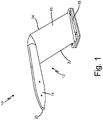
FIG. 1 is a perspective view of a pitot probe. -
FIG. 2 is a perspective view of a total air temperature probe. -
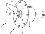
FIG. 3 is a perspective view of an angle of attack sensor. -
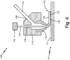
FIG. 4 is a schematic view of a system for forming an additively manufactured heater. -
FIG. 5 is a schematic view of a second embodiment of a system for forming an additively manufactured heater. - In general, the present disclosure describes a heater that is additively manufactured onto an air data probe by coaxially co-extruding a heater wire along with a dielectric material onto a substrate of the air data probe, which results in a single-step process that is simpler and more cost-effective while allowing for more tailored heating.
- The present disclosure relates to air data probes.
FIGS. 1-3 illustrate examples of different air data probes. InFIG. 1 , a pitot probe is discussed. InFIG. 2 , a total air temperature probe is discussed. InFIG. 3 , an angle of attack sensor is discussed. The present disclosure can be applied to any suitable air data probe. -
FIG. 1 is a perspective view ofpitot probe 10.Pitot probe 10 includesbody 12, formed byprobe head 14 andstrut 16, and mountingflange 18.Probe head 14 includestip 20. Strut 16 includes leadingedge 22 andtrailing edge 24. -
Pitot probe 10 may be a pitot-static probe or any other suitable air data probe.Body 12 ofpitot probe 10 is formed byprobe head 14 andstrut 16.Probe head 14 is the sensing head ofpitot probe 10.Probe head 14 is a forward portion ofpitot probe 10.Probe head 14 has one or more ports positioned inprobe head 14. Internal components ofpitot probe 10 are located withinprobe head 14.Probe head 14 is connected to a first end ofstrut 16. Probehead 14 and strut 16 make upbody 12 ofpitot probe 10.Strut 16 is blade-shaped. Internal components ofpitot probe 10 are located withinstrut 16.Strut 16 isadjacent mounting flange 18. A second end ofstrut 16 is connected to mountingflange 18. Mountingflange 18 makes up a mount ofpitot probe 10. Mountingflange 18 is connectable to an aircraft. -
Probe head 14 hastip 20 at a forward, or upstream, portion ofprobe head 14.Tip 20 is at the end ofprobe head 14 opposite the end ofprobe head 14 connected tostrut 16. Strut 16 has leadingedge 22 at a forward, or upstream, side ofstrut 16 andtrailing edge 24 at an aft, or downstream, side ofstrut 16.Leading edge 22 is oppositetrailing edge 24. -
Pitot probe 10 is configured to be installed on an aircraft.Pitot probe 10 may be mounted to a fuselage of the aircraft viamounting flange 18 and fasteners, such as screws or bolts. Strut 16 holdsprobe head 14 away from the fuselage of the aircraft to exposeprobe head 14 to external airflow.Probe head 14 takes in air from surrounding external airflow and communicates air pressures pneumatically through internal components and passages ofprobe head 14 andstrut 16. Pressure measurements are communicated to a flight computer and can be used to generate air data parameters related to the aircraft flight condition. -
FIG. 2 is a perspective view of totalair temperature probe 26. Totalair temperature probe 26 includesbody 28, formed byhead 30 andstrut 32, and mountingflange 34.Head 30 includesinlet scoop 36. Strut 32 includes leadingedge 38 andtrailing edge 40. -
Body 28 of totalair temperature probe 26 is formed byhead 30 andstrut 32.Head 30 is connected to a first end ofstrut 32. Head 30 andstrut 32 make upbody 28 of totalair temperature probe 26. Internal components of totalair temperature probe 26 are located withinstrut 32.Strut 32 isadjacent mounting flange 34. A second end ofstrut 32 is connected to mountingflange 34.Mounting flange 34 makes up a mount of totalair temperature probe 26. Mountingflange 34 is connectable to an aircraft. -
Head 30 hasinlet scoop 36, which is a forward portion of totalair temperature probe 26.Inlet scoop 36 is an opening in a forward, or upstream, end ofhead 30.Strut 32 has leadingedge 38 at a forward, or upstream, side ofstrut 32 and trailingedge 40 at an aft, or downstream, side ofstrut 32. Leadingedge 38 is opposite trailingedge 40. - Total
air temperature probe 26 is configured to be installed on an aircraft. Totalair temperature probe 26 may be mounted to a fuselage of the aircraft via mountingflange 34 and fasteners, such as screws or bolts.Strut 32 holdshead 30 away from the fuselage of the aircraft to exposehead 30 to external airflow. Air flows into totalair temperature probe 26 throughinlet scoop 36 ofhead 30. Air flows into an interior passage withinstrut 32 of totalair temperature probe 26, where sensing elements measure the total air temperature of the air. Total air temperature measurements of the air are communicated to a flight computer. Such measurements can be used to generate air data parameters related to the aircraft flight condition. -
FIG. 3 is a perspective view of angle ofattack sensor 42. Angle ofattack sensor 42 includesbody 44, formed byvane 46 andfaceplate 48, andhousing 50.Vane 46 includes leadingedge 52 and trailingedge 54. -
Body 44 of angle ofattack sensor 42 is formed byvane 46 andfaceplate 48.Vane 46 isadjacent faceplate 48.Vane 46 andfaceplate 48 make upbody 44 of angle of attack sensor.Faceplate 48 makes up a mount of angle ofattack sensor 42.Faceplate 48 is connectable to an aircraft.Faceplate 48 is positioned on and connected tohousing 50. Internal components of angle ofattack sensor 42 are located withinhousing 50.Vane 46 has leadingedge 52 at a forward, or upstream, side ofvane 46 and trailingedge 54 at an aft, or downstream, side ofvane 46. Leadingedge 52 is opposite trailingedge 54. - Angle of
attack sensor 42 is installed on an aircraft. Angle ofattack sensor 42 may be mounted to a fuselage of the aircraft viafaceplate 48 and fasteners, such as screws or bolts.Vane 46 extends outside an exterior of the aircraft and is exposed to external airflow, andhousing 50 extends within an interior of the aircraft. External airflow causesvane 46 to rotate with respect tofaceplate 48 via a series of bearings within angle ofattack sensor 42.Vane 46 rotates based on the angle at which the aircraft is flying relative to the external oncoming airflow.Vane 46 causes rotation of a vane base and vane shaft withinhousing 50. The vane shaft is coupled to a rotational sensor that measures the local angle of attack or angle of the airflow relative to the fixed aircraft structure. The measured angle of attack is communicated to a flight computer and can be used to generate air data parameters related to the aircraft flight condition. -
FIG. 4 is a schematic view ofsystem 100 for forming additively manufacturedelectric resistance heater 110 onbody 12 ofpitot probe 10.System 100 includes wire-cut mechanism 112,heating zone 114,nozzle 116,first channel 118, andsecond channel 120.Heater 110 includesheater wire 122 anddielectric material 124. -
Pitot probe 10 has the same structure and function as described with respect toFIG. 1 . In this embodiment,pitot probe 10 hasheater 110 onbody 12 ofpitot probe 10.Body 12 ofpitot probe 10 is a substrate onto whichheater 110 is formed viasystem 100.Body 12 ofpitot probe 10 may be formed using any manufacturing technique, such as casting, machining, or additive manufacturing. -
System 100 has wire-cut mechanism 112 connected toheating zone 114. In alternate embodiments,system 100 may have multiple wire-cut mechanisms 112.Heating zone 114 is a heating block.Nozzle 116 is connected toheating zone 114.Heating zone 114 is between wire-cut mechanism 112 andnozzle 116.Nozzle 116 is the extrusion head ofsystem 100.Nozzle 116 may be installed in a traditional additive manufacturing system or attached to a robotic arm for additional degrees of freedom.First channel 118 extends throughheating zone 114 from wire-cut mechanism tonozzle 116.First channel 118 also extends throughnozzle 116.Second channel 120 extends throughheating zone 114 intofirst channel 118. -
Heater wire 122 anddielectric material 124form heater 110.Heater wire 122 extends from wire-cut mechanism intofirst channel 118 such thatheater wire 122 extends intoheating zone 114.Heater wire 122 extends throughheating zone 114 withinfirst channel 118.Heater wire 122 may be made of copper, nickel, or any other suitable material.Dielectric material 124 entersheating zone 114 atsecond channel 120. In this embodiment,dielectric material 124 is a thermoplastic filament, such as ABS or Ultem. In alternate embodiments,dielectric material 124 may be any other suitable polymer (such as Teflon and silicone), one or two part epoxies that may require curing (such as thermal or UV curing) after extrusion, or any other suitable dielectric material. In alternate embodiments,dielectric material 124 may be pellets, resin, or composite materials such as ceramics.Dielectric material 124 extends throughheating zone 114 withinsecond channel 120 and intofirst channel 118. -
System 100forms heater 110 ontobody 12 ofpitot probe 10. During formation ofheater 110,pitot probe 10 may be mounted to a robotic arm to increase the complexity and degrees of freedom for applyingheater 110. Wire-cut mechanism 112cuts heater wire 122 at a pre-determined location.Heater wire 122 is fed intoheating zone 114 viafirst channel 118. One ormore heater wires 122 may be fed intoheating zone 114 and joined to change the density ofheater 110 alongbody 12. For example, the number ofheater wires 122 may be increased or decreased to vary heater wattage, mechanical crimps, or other factors for tailoring the heating ofheater 110.Dielectric material 124 is fed intoheating zone 114 viasecond channel 124.Heating zone 114heats heater wire 122 anddielectric material 124.Dielectric material 124 is heated to increase fluidity ofdielectric material 124. For example, heateddielectric material 124 is a molten polymer. In embodiments where dielectric material is a resin, heated dielectric material may be a liquid resin. Heated, or melted,dielectric material 124 entersfirst channel 118. As such,heater wire 122 anddielectric material 124 come into contact withinheating zone 114 such thatheater wire 122 is coaxially fed into heateddielectric material 124.Heater wire 122 anddielectric material 124 move intonozzle 116. -
Heater wire 122 anddielectric material 124 are coaxially co-extruded fromheating zone 114 throughnozzle 116 and ontobody 12, which formsheater 110. As such,heater 110 is formed byheater wire 122 anddielectric material 124.Heater wire 122 is fully encapsulated bydielectric material 124 asheater wire 122 anddielectric material 124exit nozzle 116.Heater 110 is deposited ontobody 12 along a pre-programmed path to achieve desired heating ofpitot probe 10. For example, the location and density ofheater 110 may be tailored to achieve more or less heat in various areas ofpitot probe 10.Heater 110 can have varying watt density and include cold leads and transitions to change the amount of heat produced byheater 110. The path for extrudingheater 110 onto body may be programmed using traditional or custom software. -
Pitot probe 10 is installed on an aircraft and subjected to icing conditions during flight.Heater 110 provides heat tobody 12 ofpitot probe 10 to prevent and remove ice growth. Different regions ofpitot probe 10 require different levels of heat.Heater 110 can be additively manufactured ontobody 12 exactly where needed to tailor heating ofpitot probe 10. For example,heater 110 can be formed closer to tip 20 (shown inFIG. 1 ). - Traditionally, heaters are brazed or installed into or onto air data probes. As such, manufacturing limitations affect where and how heaters can be placed on the air data probe. Additionally, traditional methods for installing heaters can be expensive and labor-intensive multistep processes.
- Additively
manufactured heater 110 provides more flexibility with respect to whereheater 110 can be formed onpitot probe 10 and allows for precise tailoring of heat fromheater 110 within areas ofpitot probe 10 where more or less heat is required.System 100 can be used to automate the method of installingheater 110. Coaxiallyco-extruding heater wire 122 encased withindielectric material 124 directly ontobody 12 allowsheater 110 to be formed, deposited, and adhered ontobody 12 in a single step. As a result, formingheater 110 is simpler, less labor-intensive, and more cost-effective. -
FIG. 5 is a schematic view ofsystem 200 for forming additively manufacturedelectric resistance heater 210 onbody 12 ofpitot probe 10.System 200 includes wire-cut mechanism 212,heating zone 214,nozzle 216,first channel 218, anddielectric pool 220.Heater 210 includesheater wire 222 anddielectric material 224. -
Pitot probe 10 has the same structure and function as described with respect toFIG. 1 . In this embodiment,pitot probe 10 hasheater 210 onbody 12 ofpitot probe 10.Body 12 ofpitot probe 10 is a substrate onto whichheater 210 is formed viasystem 200.Body 12 ofpitot probe 10 may be formed using any manufacturing technique, such as casting, machining, or additive manufacturing. -
System 200 has wire-cut mechanism 212 connected toheating zone 214. In alternate embodiments,system 200 may have multiple wire-cut mechanisms 212.Heating zone 214 is a heating block.Nozzle 216 is connected toheating zone 214.Heating zone 214 is between wire-cut mechanism 212 andnozzle 216.Nozzle 216 is the extrusion head ofsystem 200.Nozzle 216 may be installed in a traditional additive manufacturing system or attached to a robotic arm for additional degrees of freedom.First channel 218 extends throughheating zone 214.Dielectric pool 220 is positioned between wire-cut mechanism 212 andheating zone 214. As such, wire-cut mechanism 212 is connected toheating zone 214 viadielectric pool 220.First channel 218 extends throughheating zone 214 fromdielectric pool 220 tonozzle 216.First channel 218 also extends throughnozzle 216. -
Heater wire 222 anddielectric material 224form heater 210.Heater wire 222 extends from wire-cut mechanism throughdielectric pool 220 and intofirst channel 218 such thatheater wire 122 anddielectric material 224 extend intoheating zone 214.Heater wire 222 may be made of copper, nickel, or any other suitable material.Dielectric pool 220 containsdielectric material 224. In this embodiment,dielectric material 224 is liquid resin. In alternate embodiments,dielectric material 224 may be any suitable polymer (such as ABS, Ultem, Teflon, and silicone) anddielectric pool 220 may be heated, ordielectric material 224 may be any other suitable dielectric material. In alternate embodiments,dielectric material 224 may be pellets, filament, or composite materials such as ceramics.Heater wire 222 anddielectric material 224 enter at and extend throughheating zone 214 withinfirst channel 218. -
System 200forms heater 210 ontobody 12 ofpitot probe 10. During formation ofheater 210,pitot probe 10 may be mounted to a robotic arm to increase the complexity and degrees of freedom for applyingheater 210. Wire-cut mechanism 212cuts heater wire 222 at a pre-determined location.Heater wire 222 is run throughdielectric pool 220, andheater wire 222 is coated withdielectric material 224.Heater wire 222 is coaxially withindielectric material 224 whenheater wire 22 anddielectric material 224 exitdielectric pool 220. As such,heater wire 222 anddielectric material 224 are coaxially fed intoheating zone 214 viafirst channel 218. One ormore heater wires 222 may be joined and fed intodielectric pool 220 to change the density ofheater 210 alongbody 12. For example, the number ofheater wires 222 may be increased or decreased to vary heater wattage, mechanical crimps, or other factors for tailoring the heating ofheater 110.Heating zone 214heats heater wire 222 anddielectric material 224, andheater wire 222 anddielectric material 224 move intonozzle 216. -
Heater wire 222 anddielectric material 224 are coaxially co-extruded fromheating zone 214 throughnozzle 216 and ontobody 12, which formsheater 210. As such,heater 210 is formed byheater wire 222 anddielectric material 224.Heater wire 222 is fully encapsulated bydielectric material 224 asheater wire 222 anddielectric material 224exit nozzle 216.Heater 210 is deposited ontobody 12 along a pre-programmed path to achieve desired heating ofpitot probe 10. For example, the location and density ofheater 210 may be tailored to achieve more or less heat in various areas ofpitot probe 10.Heater 210 can have varying watt density and include cold leads and transitions to change the amount of heat produced byheater 210. The path for extrudingheater 210 onto body may be programmed using traditional or custom software. -
Pitot probe 10 is installed on an aircraft and subjected to icing conditions during flight.Heater 210 provides heat tobody 12 ofpitot probe 10 to prevent and remove ice growth. Different regions ofpitot probe 10 require different levels of heat.Heater 210 can be additively manufactured ontobody 12 exactly where needed to tailor heating ofpitot probe 10. For example,heater 210 can be formed closer to tip 20 (shown inFIG. 1 ). - Traditionally, heaters are brazed or installed into or onto air data probes. As such, manufacturing limitations affect where and how heaters can be placed on the air data probe. Additionally, traditional methods for installing heaters can be expensive and labor-intensive multistep processes.
- Additively
manufactured heater 210 provides more flexibility with respect to whereheater 210 can be formed onpitot probe 10 and allows for precise tailoring of heat fromheater 210 within areas ofpitot probe 10 where more or less heat is required.System 200 can be used to automate the method of installingheater 210. Coaxiallyco-extruding heater wire 222 encased withindielectric material 224 directly ontobody 12 allowsheater 210 to be formed, deposited, and adhered ontobody 12 in a single step. As a result, formingheater 210 is simpler, less labor-intensive, and more cost-effective. -
FIGS. 1-3 illustrate different types of air data probes on which additively manufacturedheaters heaters pitot probe 10, additively manufacturedheaters pitot probe 10, totalair temperature probe 26, angle ofattack sensor 42, or any other suitable air data probe.Heaters heaters FIG. 2 ), vane 46 (shown inFIG. 3 ), or leadingedges FIGS. 1-3 ) to provide more heat.Heaters edges FIGS. 1-3 ). Further,systems heater - The following are non-exclusive descriptions of possible embodiments of the present invention.
- A method for forming a heater on a substrate includes feeding a heater wire into a heating zone, the heater wire being in contact with a dielectric material within the heating zone; and coaxially co-extruding the heater wire and the dielectric material from the heating zone through a nozzle and onto a substrate such that the heater wire and the dielectric material form a heater for heating the substrate.
- The method of the preceding paragraph can optionally include, additionally and/or alternatively, any one or more of the following features, configurations and/or additional components:
- The heater wire is fully encapsulated by the dielectric material as the heater wire and the dielectric material exit the nozzle.
- Cutting the heater wire at a pre-determined location.
- Feeding a dielectric material into the heating zone.
- The dielectric material is a thermoplastic filament.
- Running the heater wire through a dielectric pool, the dielectric pool containing the dielectric material.
- The substrate is a body of an air data probe.
- The heater is additively manufactured onto the substrate in a single step.
- The heater has varying watt density.
- The heater includes cold leads.
- A system for forming a heater onto a substrate includes a heating zone configured to heat a heater wire and a dielectric material; and a nozzle connected to the heating zone; wherein the heater wire and the dielectric material are coaxially co-extruded from the heating zone through the nozzle and onto the substrate to form a heater for heating the substrate.
- The system of the preceding paragraph can optionally include, additionally and/or alternatively, any one or more of the following features, configurations and/or additional components:
- The heater wire is fully encapsulated by the dielectric material as the heater wire and the dielectric material exit the nozzle.
- A wire-cut mechanism connected to the heating zone, wherein the wire-cut mechanism is configured to cut the heater wire.
- A dielectric pool positioned between the wire-cut mechanism and the heating zone.
- A first channel extends through the heating zone, the heater wire extending through the heating zone within the first channel and a second channel extends through the heating zone, a dielectric material entering the heating zone within the second channel.
- The dielectric material is a thermoplastic filament.
- The substrate is a body of an air data probe.
- The heater is additively manufactured onto the substrate in a single step.
- The heater has varying watt density.
- The heater includes cold leads.
- While the invention has been described with reference to an exemplary embodiment(s), it will be understood by those skilled in the art that various changes may be made and equivalents may be substituted for elements thereof without departing from the scope of the invention as defined by the claims. In addition, many modifications may be made to adapt a particular situation or material to the teachings of the invention without departing from the scope thereof. Therefore, it is intended that the invention not be limited to the particular embodiments) disclosed, but that the invention will include all embodiments falling within the scope of the appended claims.
Claims (15)
- A method for forming a heater on a substrate, the method comprising:feeding a heater wire (122) into a heating zone (114), the heater wire being in contact with a dielectric material (124) within the heating zone; andcoaxially co-extruding the heater wire and the dielectric material from the heating zone through a nozzle (116) and onto a substrate such that the heater wire and the dielectric material form a heater for heating the substrate.
- The method of claim 1, wherein the heater wire (122) is fully encapsulated by the dielectric material (124) as the heater wire and the dielectric material exit the nozzle.
- The method of claim 1 or 2, further comprising cutting the heater wire at a pre-determined location.
- The method of any preceding claim, further comprising feeding a dielectric material into the heating zone, and optionally wherein the dielectric material is a thermoplastic filament.
- The method of any preceding claim, further comprising running the heater wire through a dielectric pool (220), the dielectric pool (220) containing the dielectric material.
- The method of any preceding claim, wherein the substrate is a body of an air data probe.
- The method of any preceding claim, wherein the heater is additively manufactured onto the substrate in a single step.
- The method of any preceding claim, wherein the heater has varying watt density, and/or wherein the heater includes cold leads.
- A system for forming a heater onto a substrate, the system comprising:a heating zone (114) configured to heat a heater wire (122) and a dielectric material (124); anda nozzle (116) connected to the heating zone;wherein the heater wire and the dielectric material are coaxially co-extruded from the heating zone through the nozzle and onto the substrate to form a heater for heating the substrate.
- The system of claim 9, wherein the heater wire is fully encapsulated by the dielectric material as the heater wire and the dielectric material exit the nozzle.
- The system of claim 9 or 10, further comprising a wire-cut mechanism (212) connected to the heating zone, wherein the wire-cut mechanism is configured to cut the heater wire, and optionally further comprising a dielectric pool (220) positioned between the wire-cut mechanism and the heating zone.
- The system of claim 9, 10 or 11, wherein a first channel (218) extends through the heating zone, the heater wire extending through the heating zone within the first channel and a second channel extends through the heating zone, a dielectric material entering the heating zone within the second channel., and optionally wherein the dielectric material is a thermoplastic filament.
- The system of any of claims 9 to 12, wherein the substrate is a body of an air data probe.
- The system of any of claims 9 to 13, wherein the heater has varying watt density.
- The system of any of claims 9 to 14, wherein the heater includes cold leads.
Applications Claiming Priority (1)
| Application Number | Priority Date | Filing Date | Title |
|---|---|---|---|
| US17/075,327 US11565463B2 (en) | 2020-10-20 | 2020-10-20 | Additively manufactured heater |
Publications (2)
| Publication Number | Publication Date |
|---|---|
| EP3989677A1 true EP3989677A1 (en) | 2022-04-27 |
| EP3989677B1 EP3989677B1 (en) | 2026-04-15 |
Family
ID=78592410
Family Applications (1)
| Application Number | Title | Priority Date | Filing Date |
|---|---|---|---|
| EP21203409.4A Active EP3989677B1 (en) | 2020-10-20 | 2021-10-19 | Additively manufactured heater |
Country Status (2)
| Country | Link |
|---|---|
| US (1) | US11565463B2 (en) |
| EP (1) | EP3989677B1 (en) |
Families Citing this family (4)
| Publication number | Priority date | Publication date | Assignee | Title |
|---|---|---|---|---|
| US12623784B2 (en) | 2022-06-17 | 2026-05-12 | Rosemount Aerospace Inc. | Additive material integrated heater deposited or embedded within magnetostrictive oscillating ice detector sensor |
| US12416485B2 (en) | 2022-06-17 | 2025-09-16 | Rosemont Aerospace Inc. | Additive material integrated heater deposited or embedded within an ice detector |
| US12479583B2 (en) | 2022-07-11 | 2025-11-25 | Rosemount Aerospace Inc. | Air data probe electronics housing with retention features |
| US12174149B2 (en) | 2022-08-18 | 2024-12-24 | Rosemount Aerospace Inc. | Variable shape sensing element of a magnetostrictive oscillating ice detector sensor for improved ice collection efficiency using additive manufacturing |
Citations (3)
| Publication number | Priority date | Publication date | Assignee | Title |
|---|---|---|---|---|
| US9126365B1 (en) * | 2013-03-22 | 2015-09-08 | Markforged, Inc. | Methods for composite filament fabrication in three dimensional printing |
| US20180186460A1 (en) * | 2017-01-03 | 2018-07-05 | Goodrich Corporation | Additive manufacturing of conformal deicing and boundary layer control surface for aircraft |
| US10254499B1 (en) * | 2016-08-05 | 2019-04-09 | Southern Methodist University | Additive manufacturing of active devices using dielectric, conductive and magnetic materials |
Family Cites Families (48)
| Publication number | Priority date | Publication date | Assignee | Title |
|---|---|---|---|---|
| US2984107A (en) | 1957-09-16 | 1961-05-16 | Us Industries Inc | Pitot static tube |
| JPS55126989A (en) | 1979-03-24 | 1980-10-01 | Kyoto Ceramic | Ceramic heater |
| US5127265A (en) | 1990-11-15 | 1992-07-07 | The Boeing Company | Flame resistant pitot probe cover |
| US5466067A (en) | 1993-09-17 | 1995-11-14 | The B. F. Goodrich Company | Multifunctional air data sensing probes |
| US5750958A (en) | 1993-09-20 | 1998-05-12 | Kyocera Corporation | Ceramic glow plug |
| JP3411498B2 (en) | 1997-04-23 | 2003-06-03 | 日本特殊陶業株式会社 | Ceramic heater, method of manufacturing the same, and ceramic glow plug |
| US6070475A (en) | 1997-10-15 | 2000-06-06 | Rosemont Aerospace Inc. | Air data probe with heater means within wall |
| US6236027B1 (en) | 1999-03-26 | 2001-05-22 | Ibiden Co., Ltd. | Ceramic heater |
| US6517240B1 (en) | 1999-11-05 | 2003-02-11 | Durametrics, Inc. | Ultrasonic thermometer system |
| US6892584B2 (en) | 2002-11-19 | 2005-05-17 | Rosemount Aerospace Inc. | Fabricated pitot probe assembly |
| US7132628B2 (en) * | 2004-03-10 | 2006-11-07 | Watlow Electric Manufacturing Company | Variable watt density layered heater |
| US8536496B2 (en) * | 2004-09-15 | 2013-09-17 | Watlow Electric Manufacturing Company | Adaptable layered heater system |
| ES2341794T3 (en) | 2005-08-25 | 2010-06-28 | Gkn Aerospace Services Limited | AUXILIARY WING OF THE WING ATTACK OF THE WING OF AN AIRPLANE. |
| US20070108047A1 (en) | 2005-11-16 | 2007-05-17 | Fenglian Chang | Sensing element and method of making the same |
| US7696455B2 (en) | 2006-05-03 | 2010-04-13 | Watlow Electric Manufacturing Company | Power terminals for ceramic heater and method of making the same |
| US20100032292A1 (en) | 2008-08-07 | 2010-02-11 | Da Yu Wang | Ammonia gas sensor |
| JP5261103B2 (en) | 2008-09-26 | 2013-08-14 | 京セラ株式会社 | Ceramic heater |
| US20120118076A1 (en) | 2010-07-19 | 2012-05-17 | Foster George B | Method of Detecting, Measuring, Correcting and Removal of Ice for a Pitot-Static Based Airspeed Detection Syeste for an Aircraft |
| KR101184780B1 (en) | 2010-12-20 | 2012-09-20 | 한국항공우주연구원 | Fabrication of deicing pitot-static probe using lamination method |
| KR101488751B1 (en) | 2011-03-31 | 2015-02-03 | 쿄세라 코포레이션 | Ceramic heater |
| US9097734B2 (en) | 2012-01-04 | 2015-08-04 | Amphenol Thermometrics, Inc. | Ceramic heating device |
| EP2717649B1 (en) | 2012-03-22 | 2016-07-27 | NGK Insulators, Ltd. | Heater |
| US20140042140A1 (en) | 2012-08-13 | 2014-02-13 | General Electric Company | Welding process for repair of thick sections |
| EP2728364B1 (en) | 2012-10-31 | 2019-04-17 | Rosemount Aerospace Inc. | Ice resistant pitot tube |
| US10562226B1 (en) * | 2013-03-15 | 2020-02-18 | Southern Methodist University | Additive manufacturing of active devices using dielectric, conductive, and magnetic materials |
| JP6038698B2 (en) | 2013-03-22 | 2016-12-07 | 日本碍子株式会社 | Ceramic member and member for semiconductor manufacturing equipment |
| FR3024124B1 (en) | 2014-07-22 | 2018-03-02 | Safran Nacelles | METHOD FOR SETTING A DEFROSTING SYSTEM ON AN AIRCRAFT COMPRISING THE DEPOSITION OF LAYERS OF MATERIALS IN THE SOLID CONDITION AND / OR FLUID |
| US20160304210A1 (en) | 2014-10-15 | 2016-10-20 | Rosemount Aerospace Inc. | One-piece air data probe |
| US10227139B2 (en) | 2015-03-23 | 2019-03-12 | Rosemount Aerospace Inc. | Heated air data probes |
| FR3039513B1 (en) | 2015-07-28 | 2017-09-01 | Thales Sa | PROCESS FOR THE ADDITIVE MANUFACTURE OF AERONAUTICAL EQUIPMENT |
| US9664542B2 (en) | 2015-08-20 | 2017-05-30 | Honeywell International Inc. | Systems and methods for additive manufacturing for air data probes |
| US9891083B2 (en) | 2016-01-08 | 2018-02-13 | Honeywell International Inc. | Probe tip for air data probe |
| EP3410819B1 (en) | 2016-01-27 | 2021-05-05 | Kyocera Corporation | Heater |
| US9719820B1 (en) | 2016-01-29 | 2017-08-01 | Goodrich Aerospace Services Private Limited | Hybrid material pitot tube |
| US10060948B2 (en) | 2016-08-12 | 2018-08-28 | Tiptek, LLC | Scanning probe and electron microscope probes and their manufacture |
| US10457412B2 (en) | 2016-09-16 | 2019-10-29 | Rosemount Aerospace Inc. | Electrical isolation of angle of attack vane bearings |
| US11297692B2 (en) | 2016-11-01 | 2022-04-05 | Goodrich Corporation | Multilayered panels |
| US10197588B2 (en) | 2016-11-09 | 2019-02-05 | Honeywell International Inc. | Thin film heating systems for air data probes |
| US11382181B2 (en) | 2016-12-02 | 2022-07-05 | Goodrich Corporation | Method to create carbon nanotube heaters with varying resistance |
| US11221346B2 (en) | 2017-03-13 | 2022-01-11 | Honeywell International Inc. | Ice prevention dam for, and method for forming, a pitot tube |
| US10889056B2 (en) | 2017-03-31 | 2021-01-12 | Purdue Research Foundation | Methods and apparatus for embedding heating circuits into articles made by additive manufacturing and articles made therefrom |
| GB2561393B (en) | 2017-04-13 | 2019-12-04 | Gkn Aerospace Services Ltd | Electrothermal heater |
| US10605675B2 (en) | 2017-06-22 | 2020-03-31 | Unison Industries, Llc | Air temperature sensor |
| US10578498B2 (en) | 2017-06-22 | 2020-03-03 | Unison Industries, Llc | Air temperature sensor |
| US10955433B2 (en) | 2018-03-23 | 2021-03-23 | Rosemount Aerospace Inc. | Hybrid material aircraft sensors having an encapsulated insert in a probe wall formed from a higher conductive material than the probe wall |
| US11130559B2 (en) | 2018-08-20 | 2021-09-28 | Goodrich Corporation | Heated panels with ballistic structures |
| US10884014B2 (en) | 2019-03-25 | 2021-01-05 | Rosemount Aerospace Inc. | Air data probe with fully-encapsulated heater |
| US11237031B2 (en) | 2019-08-20 | 2022-02-01 | Rosemount Aerospace Inc. | Additively manufactured heaters for air data probes having a heater layer and a dielectric layer on the air data probe body |
-
2020
- 2020-10-20 US US17/075,327 patent/US11565463B2/en active Active
-
2021
- 2021-10-19 EP EP21203409.4A patent/EP3989677B1/en active Active
Patent Citations (3)
| Publication number | Priority date | Publication date | Assignee | Title |
|---|---|---|---|---|
| US9126365B1 (en) * | 2013-03-22 | 2015-09-08 | Markforged, Inc. | Methods for composite filament fabrication in three dimensional printing |
| US10254499B1 (en) * | 2016-08-05 | 2019-04-09 | Southern Methodist University | Additive manufacturing of active devices using dielectric, conductive and magnetic materials |
| US20180186460A1 (en) * | 2017-01-03 | 2018-07-05 | Goodrich Corporation | Additive manufacturing of conformal deicing and boundary layer control surface for aircraft |
Also Published As
| Publication number | Publication date |
|---|---|
| EP3989677B1 (en) | 2026-04-15 |
| US11565463B2 (en) | 2023-01-31 |
| US20220118683A1 (en) | 2022-04-21 |
Similar Documents
| Publication | Publication Date | Title |
|---|---|---|
| EP3989677B1 (en) | Additively manufactured heater | |
| US12447502B2 (en) | Additively manufactured heaters for air data probes | |
| CA2927639C (en) | Sensor probe with anti-icing | |
| EP0932831B1 (en) | Heated air data probe | |
| EP3835793B1 (en) | Ceramic probe head for an air data probe | |
| US6070475A (en) | Air data probe with heater means within wall | |
| EP2863195B1 (en) | Total air temperature sensors | |
| EP3660281B1 (en) | Wear monitoring system, gas turbine engine and method of forming a wear monitoring system | |
| US11655726B2 (en) | Pressure and temperature sensors and related methods | |
| US9939247B1 (en) | Embedded sensor for in-situ monitoring of blade tip incursion | |
| US11668727B2 (en) | Inductive heating of air data probes | |
| US12180852B2 (en) | Pressure and temperature sensors and methods of removing ice from pressure and temperature sensors | |
| EP4160221B1 (en) | Air data probe with enhanced conduction integrated heater bore | |
| US20230375417A1 (en) | Methods for reducing acoustic noise on total air temperature sensors using additive manufacturing | |
| US6250801B1 (en) | Probed for measuring physical parameters of a fluid flow | |
| EP4304938B1 (en) | Anti-icing device for intake opening of the engine nacelle for turbojet or turbofan engines | |
| EP4111211B1 (en) | Angle of attack sensor vane geometry |
Legal Events
| Date | Code | Title | Description |
|---|---|---|---|
| PUAI | Public reference made under article 153(3) epc to a published international application that has entered the european phase |
Free format text: ORIGINAL CODE: 0009012 |
|
| STAA | Information on the status of an ep patent application or granted ep patent |
Free format text: STATUS: THE APPLICATION HAS BEEN PUBLISHED |
|
| AK | Designated contracting states |
Kind code of ref document: A1 Designated state(s): AL AT BE BG CH CY CZ DE DK EE ES FI FR GB GR HR HU IE IS IT LI LT LU LV MC MK MT NL NO PL PT RO RS SE SI SK SM TR |
|
| STAA | Information on the status of an ep patent application or granted ep patent |
Free format text: STATUS: REQUEST FOR EXAMINATION WAS MADE |
|
| 17P | Request for examination filed |
Effective date: 20221027 |
|
| RBV | Designated contracting states (corrected) |
Designated state(s): AL AT BE BG CH CY CZ DE DK EE ES FI FR GB GR HR HU IE IS IT LI LT LU LV MC MK MT NL NO PL PT RO RS SE SI SK SM TR |
|
| STAA | Information on the status of an ep patent application or granted ep patent |
Free format text: STATUS: EXAMINATION IS IN PROGRESS |
|
| 17Q | First examination report despatched |
Effective date: 20250624 |
|
| GRAP | Despatch of communication of intention to grant a patent |
Free format text: ORIGINAL CODE: EPIDOSNIGR1 |
|
| STAA | Information on the status of an ep patent application or granted ep patent |
Free format text: STATUS: GRANT OF PATENT IS INTENDED |
|
| INTG | Intention to grant announced |
Effective date: 20251121 |
|
| GRAS | Grant fee paid |
Free format text: ORIGINAL CODE: EPIDOSNIGR3 |
|
| GRAA | (expected) grant |
Free format text: ORIGINAL CODE: 0009210 |
|
| STAA | Information on the status of an ep patent application or granted ep patent |
Free format text: STATUS: THE PATENT HAS BEEN GRANTED |
|
| AK | Designated contracting states |
Kind code of ref document: B1 Designated state(s): AL AT BE BG CH CY CZ DE DK EE ES FI FR GB GR HR HU IE IS IT LI LT LU LV MC MK MT NL NO PL PT RO RS SE SI SK SM TR |
|
| REG | Reference to a national code |
Ref country code: CH Ref legal event code: F10 Free format text: ST27 STATUS EVENT CODE: U-0-0-F10-F00 (AS PROVIDED BY THE NATIONAL OFFICE) Effective date: 20260415 |
|
| REG | Reference to a national code |
Ref country code: DE Ref legal event code: R096 Ref document number: 602021052027 Country of ref document: DE |