EP3989372A2 - Anti-vibration stabilized connected system with selfrejecting ergonomic feedback mechanism - Google Patents
Anti-vibration stabilized connected system with selfrejecting ergonomic feedback mechanism Download PDFInfo
- Publication number
- EP3989372A2 EP3989372A2 EP21203864.0A EP21203864A EP3989372A2 EP 3989372 A2 EP3989372 A2 EP 3989372A2 EP 21203864 A EP21203864 A EP 21203864A EP 3989372 A2 EP3989372 A2 EP 3989372A2
- Authority
- EP
- European Patent Office
- Prior art keywords
- connector body
- stage position
- cpa
- full
- corresponding mating
- Prior art date
- Legal status (The legal status is an assumption and is not a legal conclusion. Google has not performed a legal analysis and makes no representation as to the accuracy of the status listed.)
- Pending
Links
Images


Classifications
-
- H—ELECTRICITY
- H01—ELECTRIC ELEMENTS
- H01R—ELECTRICALLY-CONDUCTIVE CONNECTIONS; STRUCTURAL ASSOCIATIONS OF A PLURALITY OF MUTUALLY-INSULATED ELECTRICAL CONNECTING ELEMENTS; COUPLING DEVICES; CURRENT COLLECTORS
- H01R13/00—Details of coupling devices of the kinds covered by groups H01R12/70 or H01R24/00 - H01R33/00
- H01R13/62—Means for facilitating engagement or disengagement of coupling parts or for holding them in engagement
- H01R13/627—Snap or like fastening
- H01R13/6271—Latching means integral with the housing
- H01R13/6272—Latching means integral with the housing comprising a single latching arm
-
- H—ELECTRICITY
- H01—ELECTRIC ELEMENTS
- H01R—ELECTRICALLY-CONDUCTIVE CONNECTIONS; STRUCTURAL ASSOCIATIONS OF A PLURALITY OF MUTUALLY-INSULATED ELECTRICAL CONNECTING ELEMENTS; COUPLING DEVICES; CURRENT COLLECTORS
- H01R13/00—Details of coupling devices of the kinds covered by groups H01R12/70 or H01R24/00 - H01R33/00
- H01R13/46—Bases; Cases
- H01R13/516—Means for holding or embracing insulating body, e.g. casing, hoods
-
- H—ELECTRICITY
- H01—ELECTRIC ELEMENTS
- H01R—ELECTRICALLY-CONDUCTIVE CONNECTIONS; STRUCTURAL ASSOCIATIONS OF A PLURALITY OF MUTUALLY-INSULATED ELECTRICAL CONNECTING ELEMENTS; COUPLING DEVICES; CURRENT COLLECTORS
- H01R13/00—Details of coupling devices of the kinds covered by groups H01R12/70 or H01R24/00 - H01R33/00
- H01R13/46—Bases; Cases
- H01R13/502—Bases; Cases composed of different pieces
- H01R13/506—Bases; Cases composed of different pieces assembled by snap action of the parts
-
- H—ELECTRICITY
- H01—ELECTRIC ELEMENTS
- H01R—ELECTRICALLY-CONDUCTIVE CONNECTIONS; STRUCTURAL ASSOCIATIONS OF A PLURALITY OF MUTUALLY-INSULATED ELECTRICAL CONNECTING ELEMENTS; COUPLING DEVICES; CURRENT COLLECTORS
- H01R13/00—Details of coupling devices of the kinds covered by groups H01R12/70 or H01R24/00 - H01R33/00
- H01R13/62—Means for facilitating engagement or disengagement of coupling parts or for holding them in engagement
- H01R13/639—Additional means for holding or locking coupling parts together, after engagement, e.g. separate keylock, retainer strap
-
- H—ELECTRICITY
- H01—ELECTRIC ELEMENTS
- H01R—ELECTRICALLY-CONDUCTIVE CONNECTIONS; STRUCTURAL ASSOCIATIONS OF A PLURALITY OF MUTUALLY-INSULATED ELECTRICAL CONNECTING ELEMENTS; COUPLING DEVICES; CURRENT COLLECTORS
- H01R13/00—Details of coupling devices of the kinds covered by groups H01R12/70 or H01R24/00 - H01R33/00
- H01R13/64—Means for preventing incorrect coupling
- H01R13/641—Means for preventing incorrect coupling by indicating incorrect coupling; by indicating correct or full engagement
-
- H—ELECTRICITY
- H01—ELECTRIC ELEMENTS
- H01R—ELECTRICALLY-CONDUCTIVE CONNECTIONS; STRUCTURAL ASSOCIATIONS OF A PLURALITY OF MUTUALLY-INSULATED ELECTRICAL CONNECTING ELEMENTS; COUPLING DEVICES; CURRENT COLLECTORS
- H01R13/00—Details of coupling devices of the kinds covered by groups H01R12/70 or H01R24/00 - H01R33/00
- H01R13/46—Bases; Cases
- H01R13/533—Bases, cases made for use in extreme conditions, e.g. high temperature, radiation, vibration, corrosive environment, pressure
Definitions
- the present invention relates generally to electrical connectors and in particular to a connector position assurance feature that limits vibration.
- a connector body typically includes a latch or retention assembly utilized to maintain connector halves (i.e., male connector and a female connector) in a fully mated position.
- connector position assurance (CPA) features are utilized to ensure that the connectors are fully mated.
- CPA connector position assurance
- a CPA is a feature that can be moved to a closed position only when the connector halves are fully mated with one another. In this way, a closed CPA provides visual assurance that the connector halves are fully mated.
- a connector assembly includes a connector body, a corresponding mating connector body, and a connection position assurance (CPA) device.
- the connector body includes a deflectable latching member and at least one outer detent feature located on an outer surface of the connector body.
- the corresponding mating connector body is configured to be removably connected with the connector body, wherein the deflectable latching member is configured to secure the connector body to the corresponding mating connector body.
- connection position assurance (CPA) device is slidably positioned adjacent the connector body and moveable from a pre-stage position to a full-stage position, wherein the CPA device interacts with the at least one outer detent feature located on the outer surface of the connector body to deflect the connector body towards the corresponding mating connector body.
- a method of operating a connector assembly includes mating a connector body with a corresponding mating connector body, wherein the connector body includes a deflectable latching member configured to interact with a latching nib located on the corresponding mating connector body.
- a connector position assurance (CPA) device is moved from a pre-stage position that allows the latching member to deflect to a full-stage position that prevents the latching member from deflecting, wherein the CPA device interacts with an outer detent feature located on the outer surface of the connector body to deflect the connector body towards the corresponding mating connector body in the full-stage position.
- CPA connector position assurance
- a connector assembly includes a connector body, a corresponding mating connector body, and a connection position assurance (CPA) device.
- the connector body includes a deflectable latching member and at least one outer detent feature located on an outer surface of the connector body.
- the corresponding mating connector body is configured to be removably connected with the connector body, wherein the deflectable latching member is configured to secure the connector body to the corresponding mating connector body.
- the connection position assurance (CPA) device includes a spring over stress protection feature and a hoop spring surrounding the spring over stress protection feature, wherein the hoop spring is deflected by the latching member as the CPA device is moved from a pre-stage position to a full-stage position. The hoop spring snaps over the deflectable latching member when in the full-stage position and the spring over stress protection feature interacts with the deflectable latching member to prevent deflecting of the latching member.
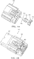
- Figure 1A and 1B is a perspective view of a connector assembly 100 having a sliding connector position assurance (CPA) sleeve 106 according to some embodiments
- 1B is a perspective view of a connector body having a sliding CPA sleeve according to some embodiments.
- CPA connector position assurance
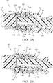
- Figures 2A and 2B are cross-sectional views that illustrate the sliding CPA sleeve in an open position and a mated position, respectively, according to some embodiments.
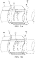
- Figures 3A and 3B are perspective views of a connector body having a sliding CPA sleeve and a spring element configured to provide a spring back function if the connector assembly is not fully mated according to some embodiments.
- Figures 4A and 4B are perspective views of a connector assembly that includes a self-rejecting CPA spring according to some embodiments;
- Figures 4C and 4D are cross-sectional views of a connector assembly that includes a self-rejecting CPA spring according to some embodiments.
- the present invention is directed generally to a connector assembly that includes connector body, a corresponding mating connector body, and a connector position assurance (CPA) device.
- the connector body is mated with the corresponding mating connector body.
- the CPA device is utilized to ensure that the connector bodies are fully engaged with one another by sliding the CPA device from a first pre-stage position to a second, full-stage position.
- the CPA device provides tactile feedback to an operator indicating whether the CPA device has been fully closed or seated in the full-stage position.
- the CPA device deflects the connector body toward the corresponding mating connector body, essentially "cinching" the connectors together to reduce the impact of vibration on the connector assembly.
- additional features such as self-rejecting spring features may be utilized to provide additional, visual feedback that the CPA device is not fully seated in the full-stage position.
- a connector assembly 100 that includes a sliding connection position assurance (CPA) sleeve 106 according to some embodiments.
- Connector assembly 100 includes a connector body 104 and a corresponding mating connector body 102 configured to be removably connected with the connector body 104.
- connector body 104 includes a plurality of walls - including top wall 108, side walls 110 and 114, and bottom wall 112 that defines a cavity for receiving the corresponding mating connector body 102.
- one or more of the walls includes a deflectable latch (not shown) that is utilized to secure the connector body 104 to the corresponding mating connector body 102.
- corresponding mating connector body 102 comprises a plurality of walls - including side walls 130, 132, top wall 134 and a bottom wall 136.
- the corresponding mating connector body 102 further includes a pair of guide walls 138 and 141 extending vertically from the top wall 134.
- Corresponding mating connector body 102 is configured to fit within the cavity defined by the plurality of walls associated with connector body 104.
- connector body 104 includes one or more deflectable latching members (e.g., deflectable latching member 116 located on the top wall 108) configured to interact with a corresponding feature (e.g., not shown in this embodiment) located on the corresponding mating connector body 102.
- the deflectable latching member 116 is deflected in response to engagement of the connector body 104 with the corresponding feature on the corresponding mating connector body 102. When fully engaged the deflectable latching member 116 captures the corresponding feature on the corresponding mating connector body 102, providing a mechanical connection between the connector body 104 and the corresponding mating connector body 102.
- the deflectable latching member 116 is located on the top wall 108 of the connector body 104 and the corresponding feature is located on the top wall 134 of the corresponding mating connector body 102.
- At least one of the plurality of walls 108, 110, 112, and/or 114 includes an inertial detent feature that interacts with the sliding CPA sleeve 106.
- each of the plurality of walls 108, 110, 112, and 114 includes an inertial detent feature.
- an inertial detent feature is associated with deflectable latching member 116.
- another inertial detent feature 118 is visible on side wall 110.
- the inertial detent features 118 includes a raised portion that extends or protrudes from the surface of the corresponding wall.
- the inertial detent features include a ramp on the side facing the CPA sleeve 106 that interacts with corresponding inertial detent features located on an inner surface of the CPA sleeve 106 to allow movement between the respective inertial detent features.
- CPA sleeve 106 is utilized to ensure that the connector body 104 is fully engaged and connected with the corresponding mating connector body 102.
- CPA sleeve 106 is slidably positioned adjacent to the connector body 104 and is moveable in a longitudinal direction from a pre-stage position to a full-stage position.
- the purpose of the CPA sleeve 106 is to provide both tactile, audio, and/or visual confirmation that the connector body 104 and corresponding mating connector body 102 are fully engaged.
- the CPA sleeve 106 can only be placed in the full-stage position when the connector bodies are fully engaged. In the event the connector bodies are not fully engaged, the CPA sleeve 106 will not be slidable to the full-stage position.
- the CPA sleeve 106 further includes one or more ergonomic grips 120, 122 utilized by an operator to slide the CPA sleeve 106 from the pre-stage position to the full-stage position.
- an additional ergonomic rib 124 is located on an outer surface of the CPA sleeve 106 and can be utilized by an operator to push the CPA sleeve from the pre-stage position to the full-stage position (or vice versa).
- the CPA sleeve 106 is positioned to surround the connector body 104.
- the connector body 104 includes a plurality of walls 108, 110, 112, and 114, wherein CPA sleeve 106 surrounds the plurality of walls making up the connector body 104.
- CPA sleeve 106 slides in a longitudinal direction between a pre-stage position and a full-stage position.
- Figure 1B illustrates the CPA sleeve 106 in a pre-stage position.
- the deflectable latching member 116 can be deflected via engagement with the corresponding feature located on the corresponding mating connector body 102.
- the CPA sleeve 106 includes a plurality of corresponding inertial detent features that interact with the inertial detent features (e.g., inertial detent features 118) located on the outer surface of one or more of the plurality of walls during transition from the pre-stage position to the full-stage position.
- the interaction between the inertial detent features located on one or more of the plurality of walls with the corresponding inertial detent features located on the CPA sleeve 106 presents a resistance to the sliding of the CPA sleeve 106 that must be overcome by a threshold level of force from the operator/technician to cause the inertial detent features to slide past one another to the full-stage position.
- the resistance provided by the interaction of the inertial detents and corresponding release when they move past one another provides a tactile response (e.g., ergonomic "inertial release") that is detectable by the operator, confirming that the CPA sleeve 106 is fully seated in the full-stage position.
- the CPA sleeve 106 causes the one or more walls of the connector body 104 to deflect inward toward the walls of the corresponding mating connector body 102. This deflection of the one or more walls of the connector body 104 towards the walls of the corresponding mating connector body 102 provides an additional force (e.g., a cinching force) that reduces vibration between the respective connectors.
- the CPA sleeve 106 is manufactured using additive manufacturing (i.e., 3D printing techniques) that allow the CPA sleeve 106 to be built surrounding the connector body 104.
- the materials and/or size of the CPA sleeve 106 is selected to provide increased rigidity relative to the walls of the connector body 104. This ensures that force applied by the CPA sleeve 106 results in deflection of one or more walls of the connector body 104 towards the corresponding mating connector body 102 rather than resulting in a deflection of the CPA sleeve 106.
- the CPA sleeve 106 completely surrounds the connector body 104. In other embodiments, the CPA sleeve 106 only partially surrounds the connector body 104.
- the corresponding mating connector body 102 includes side walls 130 and 132 located opposite one another.
- coupling of connector body 104 with the corresponding mating connector body 102 includes sliding the side walls 130 and 132 within the cavity defined - at least in part - by side walls 110 and 114 of the connector body 104.
- one or more seals 128 located within the interior cavity of the connector body 104 engage the inner surface of side walls 130 and 132 to prevent liquid and/or debris from degrading the performance of the connector.
- one or more deflectable latching members located on one or more of the plurality of walls associated with the connector body 104 would engage with one or more corresponding latching nib features (e.g., shark fin feature) associated with the corresponding mating connector body 102.
- latching nib features e.g., shark fin feature
- the CPA sleeve 106 is in the pre-stage position.
- the CPA sleeve 106 surrounds the connector body 104, and is configured to allow the CPA sleeve 106 to slide in a longitudinal direction.
- the connector body 104 includes one or more inertial detent features 118 protruding from an outer surface of one or more of the plurality of walls (e.g., side walls 110 and/or 114).
- CPA sleeve 106 includes one or more corresponding inertial detent features 126 extending from an inner surface of the toward the connector body 104.
- the inertial detent feature 118 does not interact with the corresponding inertial detent feature 126.
- the inertial detent feature 118 is located adjacent to or outside of CPA sleeve 106.
- the connector body 104 may further include a recessed feature 140 that corresponds with the position of the inertial detent feature 126 in the pre-stage position.
- the alignment between the inertial detent feature 126 and the recessed feature 140 prevents the CPA sleeve 106 from deflecting or otherwise cinching the one or more walls associated with the connector body 104. This allows the corresponding mating connector body 102 to be coupled with the connector body 104.
- the CPA sleeve 106 may be slid longitudinally along the axis of the connector assembly from the pre-stage position (shown in Figure 2A ) to the full-stage position (shown in Figure 2B ).
- the interaction between the inertial detent feature 118 associated with the outer surface of the connector body 104 and the corresponding inertial detent feature 126 associated with the interior surface of the CPA sleeve 106 provides an ergonomic resistance to the sliding of the CPA sleeve 106. That is, the operator sliding the CPA sleeve 106 will be required to exert a detectable level of force in engaging the respective detent features.
- the inertial detent feature 118 includes a ramp that allows the corresponding inertial detent feature to slide over the inertial detent feature 118.
- the force exerted by the CPA sleeve 106 causes the one or more walls associated with the connector body 104 to deflect inward. The deflection of the one or more walls results in the storing of spring energy.
- the CPA sleeve 106 reaches the full-stage position when the corresponding inertial detent feature 126 is slid to the opposite side of the inertial detent feature 118.
- the inertial detent feature 126 associated with the CPA sleeve 106 remains engaged with the outer surface of the connector body 104.
- an "inertial release” is detectable by the operator. This "inertial release” provides tactile feedback to the operator indicating that the CPA sleeve 106 is in the full-stage position.
- the corresponding inertial detent feature 126 remains in contact with the outer surface of the connector body 104.
- contact between the inertial detent feature 126 and the outer surface of the connector body 104 in the full-stage position provides at least some deflection of the one or more walls associated with the connector body 104.
- the plurality of walls associated with the connector body 104 are deflected toward the corresponding mating connector body 102 - in effect cinching the connector body 104 with the corresponding mating connector body 102.
- One of the benefits of cinching the connector body 104 with the corresponding mating connector body 102 is the limiting of vibration between the connector body 104 and the corresponding mating connector body 102 during operation.
- inertial detent features are located on each of the plurality of walls associated with the connector body 104 and correspondingly with the CPA sleeve 106 such that each of the plurality of walls are deflected inward to cinch the connector body 104 against the corresponding mating connector body 102.
- inertial detent features are not required on each of the plurality of walls.
- inertial detent features are located on only two of the plurality of walls.
- CPA sleeve 106 may not be required to completely surround the connector body 104.
- the CPA sleeve 106 may only partially surround the connector body, so long as the same functional interaction between the CPA sleeve 106 and the connector body 104 is achieved.
- FIGS 3A and 3B are perspective views of a connector assembly 300 according to some embodiments.
- Connector assembly 300 includes connector body 304, corresponding mating connector body 302, and CPA sleeve 306.
- CPA sleeve 306 is slidingly engaged with connector body 304, and slides longitudinally between a pre-stage position and a full-stage position. In the pre-stage position, corresponding mating connector body 302 is engaged with connector body 304. Once engaged, CPA sleeve 306 is slid in a longitudinal direction indicated by arrow 310 from the pre-stage position to a full-stage position.
- One or more inertial detent features located on an outer surface of the connector body 304 interact with one or more corresponding inertial detent features (also not shown in this view) to provide an ergonomic resistance to the sliding of the CPA sleeve 306. That is, the operator sliding the CPA sleeve 306 will be required to exert a detectable level of force in engaging the respective detent features. Interaction of the inertial detent features causes the plurality of walls associated with the connector body 304 to deflect inward, storing spring energy as a result. The full-stage position is reached when the inertial detent feature associated with the CPA sleeve 306 slides past the inertial detent feature associated with the connector body 304.
- the respective inertial detents prevent the CPA sleeve 306 from being disengaged (i.e., moved from the full-stage position to the pre-stage position).
- the inertial detent feature associated with the CPA sleeve 306 may remain in contact with the outer surface of the connector body 304, providing continued deflection of one or more of the plurality of walls associated with the connector body 304 toward the corresponding mating connector body 302. This provides a "cinching" of the connector body 304 with the corresponding mating connector body 302 that reduces motion between the respective bodies caused by vibration.
- the connector body 304 further includes a spring element 308 that interacts with the CPA sleeve 306 during closing of the CPA sleeve 306 (i.e., movement of the CPA sleeve 306 from the pre-stage position to the full-stage position).
- the spring element 308 acts to self-reject improper or partial closure of the CPA sleeve 306. As shown in Figure 3A , as the CPA sleeve 306 is moved towards the full-stage position, the spring element 308 is deformed - thereby storing elastic energy.
- the spring element 308 snaps over or releases the stored energy (as shown in Figure 3B ) in response to the CPA sleeve 306 reaching the full-stage position. However, prior to reaching the full-stage position, if the CPA sleeve 306 is released by the operator, the energy stored in the spring element 308 rejects the CPA sleeve 306, causing the CPA sleeve to return to the pre-stage position. That is, the spring element 308 causes a spring-back back of the CPA sleeve 306 if the CPA sleeve 306 is not fully engaged in the full-stage position.
- Interaction between the CPA sleeve 306 and the spring element 308 located on the connector body 304 may utilize corresponding detent features (a first detent located on the spring element 308 and a second detent feature located on the inner surface of the CPA sleeve 306).
- the force applied by moving the CPA sleeve 306 to the full-stage position overcomes the spring force exerted by the spring element 308, allowing the CPA sleeve 306 to snap over the spring element 308 as shown in Figure 3B .
- the spring element is no longer deflected, and therefore no longer stores any elastic energy.
- a benefit of the embodiment shown in Figures 3A and 3B is that it CPA sleeve 306 is self-rejected, in that if the respective connector bodies are not fully engaged and the CPA sleeve 306 is not fully engaged in the full-stage position, the CPA sleeve is sprung back to the pre-stage position (or approximately to the pre-stage position). This provides visual feedback to the operator regarding the status of the CPA sleeve 306 (i.e., whether it is fully engaged or not).
- the connector assembly 400 further includes a connector body 404 (e.g., female connector) and a corresponding mating connector body 402 (e.g., male connector) that interacts with the connector body 404.
- Connector body 404 is comprised of a plurality of walls that form a cavity for receiving the corresponding mating connector body 402 (shown in Figure 4B ).
- the connector body 404 includes a deflectable latching member 410 (shown in Figures 4C and 4D ) configured to interact with a corresponding latching nib feature 411 (e.g., shark fin, shown in Figures 4C and 4D ) to engage/lock the connector body 404 to the corresponding mating connector body 402.
- a deflectable latching member 410 is secured on the opposite side of corresponding latching nib feature 411 to prevent the respective connector bodies from becoming detached.
- the self-rejecting CPA device 406 is utilized to ensure proper engagement between the connector body 104 and the corresponding mating connector body 102.
- the self-rejecting CPA 406 includes an inner arm 412 (sometimes referred to as an over stress protection feature), a hoop spring 414, and a tab 416 for use by an operator to push the self-rejecting CPA device 406 from a pre-stage position to a full-stage position.
- the inner arm 412 extends into the interior portion of the hoop spring 414, which surrounds the inner arm 412.
- the distal end of the hoop spring 414 includes a detent feature 418 that interacts with connector body 404 during engagement of the CPA device 406 from the pre-stage position to the full-stage position.
- connector body 404 is fully engaged with corresponding mating connector body 402.
- deflectable latching member 410 associated with connector body 404 is positioned on the opposite side of the corresponding latching nib feature 411 utilized to deflect and capture the deflectable latching member 410.
- the deflectable latching member 410 would remain in a deflected position that would interfere and prevent the CPA device 406 from moving to the full-stage position.
- the detent feature 418 located at the distal end of the hoop spring 414 - is able to slide over the corresponding latching nib feature 411 as shown in Figure 4D .
- Interaction between the detent feature 418 and the corresponding latching nib feature 411 causes the hoop spring 414 to deflect.
- the detent feature 418 clears the latching nib feature 411 and deflectable latching member 410, the energy stored in the deflected hoop spring 414 causes it to snap over. In this way, the hoop spring 414 provides audible feedback to the operator assuring the operator that the CPA device 406 is in the full-stage position.
- elastic energy stored in the hoop spring as it is deflected provides self-rejecting functionality to the CPA device 406. For example, if an operator engages the CPA device 406 only partially from the pre-stage position to the full-stage position, the elastic energy stored in the hoop spring 414 causes the CPA device 406 to move back to the pre-stage position if released by the operator.
- the CPA device 406 also provides easy visual confirmation that the connectors are fully engaged, as the CPA device 406 will either be in the full-stage position or rejected and pushed to the pre-stage position.
- a connector assembly includes a connector body, a corresponding mating connector body, and a connection position assurance (CPA) device.
- the connector body includes a deflectable latching member and at least one outer detent feature located on an outer surface of the connector body.
- the corresponding mating connector body is configured to be removably connected with the connector body, wherein the deflectable latching member is configured to secure the connector body to the corresponding mating connector body.
- connection position assurance (CPA) device is slidably positioned adjacent the connector body and moveable from a pre-stage position to a full-stage position, wherein the CPA device interacts with the at least one outer detent feature located on the outer surface of the connector body to deflect the connector body towards the corresponding mating connector body.
- the connector assembly of the preceding paragraph can optionally include, additionally and/or alternatively any, one or more of the following features, configurations, and/or additional components.
- the CPA device may include an inner detent feature located on an inner surface of the CPA device that interacts with the outer detent feature located on the outer surface of the connector body, wherein the inner detent feature interacts with the outer detent feature when moving from the -pre-stage position to the full-stage position.
- the CPA device may be a sleeve that surrounds the connector body.
- the corresponding mating connector body may include a latching nib, wherein the deflectable latching member is deflected by engagement with the latching nib.
- the deflectable latching member and the latching nib may inhibit movement of the CPA device from the pre-stage position to the full-stage position until the connector body is fully mated with the corresponding mating connector body.
- the CPA device may prevent deflection of the deflectable latching member when in the full-stage position.
- the connector body may further includes at least one spring element that is deflected in response to the CPA device slidably moving from the pre-stage position to the full-stage position, wherein the spring element snaps over in response to the CPA device reaching the full-stage position.
- the at least one spring element may store energy in response to the CPA device moving longitudinally from the pre-stage position to the full-stage position, wherein the energy stored in the spring element causes the CPA device to spring back if not in the full-stage position.
- the connector body may include a first plurality of walls and wherein outer detent features are located on one or more of the first plurality of walls.
- the corresponding mating connector body may include a second plurality of walls located inward of the first plurality of walls when the corresponding mating connector body is connected with the connector body, wherein movement of the CPA device from the pre-stage position to the full-stage position causes one or more of the first plurality of walls to deflect towards the second plurality of walls.
- a method for operating a connector assembly includes mating a connector body with a corresponding mating connector body, wherein the connector body includes a deflectable latching member configured to interact with a latching nib located on the corresponding mating connector body.
- the method further includes moving a connector position assurance (CPA) device from a pre-stage position that allows the latching member to deflect to a full-stage position that prevents the latching member from deflecting, wherein the CPA device interacts with an outer detent feature located on the outer surface of the connector body to deflect the connector body towards the corresponding mating connector body in the full-stage position.
- CPA connector position assurance
- the method of the preceding paragraph can optionally include, additionally and/or alternatively any, one or more of the following features, configurations and/or additional components.
- the method may further include providing tactile feedback to an operator based on interaction of the CPA device with the outer detent feature of the connector body, wherein the tactile feedback indicates whether the CPA device is in the full-stage position.
- the method may further include providing visual feedback to an operator based on a position of the CPA device.
- the CPA device may be a sleeve that surrounds the connector body.
- the connector body may be a female connector and the corresponding mating connector body may be a male connector.
- a self-rejecting feature located on the connector body may interact with the CPA device to cause the CPA device to spring back to the pre-stage position if not moved fully to the full-stage position.
- the self-rejecting feature may be a spring located on an outer surface of the connector body, wherein the spring stores energy when moving the CPA device from the pre-stage position to the full-stage position, wherein the springs snaps over when the CPA device is fully moved to the full-stage position.
- a connector assembly includes a connector body, a corresponding mating connector body, and a connection position assurance (CPA) device.
- the connector body includes a deflectable latching member and at least one outer detent feature located on an outer surface of the connector body.
- the corresponding mating connector body is configured to be removably connected with the connector body, wherein the deflectable latching member is configured to secure the connector body to the corresponding mating connector body.
- the connection position assurance (CPA) device includes a spring over stress protection feature and a hoop spring surrounding the spring over stress protection feature, wherein the hoop spring is deflected by the latching member as the CPA device is moved from a pre-stage position to a full-stage position. The hoop spring snaps over the deflectable latching member when in the full-stage position and the spring over stress protection feature interacts with the deflectable latching member to prevent deflecting of the latching member.
- the connector assembly of the preceding paragraph can optionally include, additionally and/or alternatively any, one or more of the following features, configurations, and/or additional components.
- the hoop spring may provide an audible feedback in response to the CPA device reaching the full-stage position.
- the CPA device may provide visual feedback in response to the CPA device reaching the full-stage position.
Landscapes
- Details Of Connecting Devices For Male And Female Coupling (AREA)
- Connector Housings Or Holding Contact Members (AREA)
Abstract
Description
- The present invention relates generally to electrical connectors and in particular to a connector position assurance feature that limits vibration.
- Electrical connectors are used prominently in automotive applications. Typically, a connector body includes a latch or retention assembly utilized to maintain connector halves (i.e., male connector and a female connector) in a fully mated position. In some applications, connector position assurance (CPA) features are utilized to ensure that the connectors are fully mated. In general, a CPA is a feature that can be moved to a closed position only when the connector halves are fully mated with one another. In this way, a closed CPA provides visual assurance that the connector halves are fully mated.
- According to one aspect, a connector assembly is provided that includes a connector body, a corresponding mating connector body, and a connection position assurance (CPA) device. The connector body includes a deflectable latching member and at least one outer detent feature located on an outer surface of the connector body. The corresponding mating connector body is configured to be removably connected with the connector body, wherein the deflectable latching member is configured to secure the connector body to the corresponding mating connector body. The connection position assurance (CPA) device is slidably positioned adjacent the connector body and moveable from a pre-stage position to a full-stage position, wherein the CPA device interacts with the at least one outer detent feature located on the outer surface of the connector body to deflect the connector body towards the corresponding mating connector body.
- According to another aspect, a method of operating a connector assembly includes mating a connector body with a corresponding mating connector body, wherein the connector body includes a deflectable latching member configured to interact with a latching nib located on the corresponding mating connector body. A connector position assurance (CPA) device is moved from a pre-stage position that allows the latching member to deflect to a full-stage position that prevents the latching member from deflecting, wherein the CPA device interacts with an outer detent feature located on the outer surface of the connector body to deflect the connector body towards the corresponding mating connector body in the full-stage position.
- According to another aspect, a connector assembly includes a connector body, a corresponding mating connector body, and a connection position assurance (CPA) device. The connector body includes a deflectable latching member and at least one outer detent feature located on an outer surface of the connector body. The corresponding mating connector body is configured to be removably connected with the connector body, wherein the deflectable latching member is configured to secure the connector body to the corresponding mating connector body. The connection position assurance (CPA) device includes a spring over stress protection feature and a hoop spring surrounding the spring over stress protection feature, wherein the hoop spring is deflected by the latching member as the CPA device is moved from a pre-stage position to a full-stage position. The hoop spring snaps over the deflectable latching member when in the full-stage position and the spring over stress protection feature interacts with the deflectable latching member to prevent deflecting of the latching member.
-
Figure 1A and 1B is a perspective view of aconnector assembly 100 having a sliding connector position assurance (CPA)sleeve 106 according to some embodiments 1B is a perspective view of a connector body having a sliding CPA sleeve according to some embodiments. -
Figures 2A and 2B are cross-sectional views that illustrate the sliding CPA sleeve in an open position and a mated position, respectively, according to some embodiments. -
Figures 3A and 3B are perspective views of a connector body having a sliding CPA sleeve and a spring element configured to provide a spring back function if the connector assembly is not fully mated according to some embodiments. -
Figures 4A and 4B are perspective views of a connector assembly that includes a self-rejecting CPA spring according to some embodiments;Figures 4C and 4D are cross-sectional views of a connector assembly that includes a self-rejecting CPA spring according to some embodiments. - The present invention is directed generally to a connector assembly that includes connector body, a corresponding mating connector body, and a connector position assurance (CPA) device. The connector body is mated with the corresponding mating connector body. The CPA device is utilized to ensure that the connector bodies are fully engaged with one another by sliding the CPA device from a first pre-stage position to a second, full-stage position. In particular, the CPA device provides tactile feedback to an operator indicating whether the CPA device has been fully closed or seated in the full-stage position. In addition, in some embodiments the CPA device deflects the connector body toward the corresponding mating connector body, essentially "cinching" the connectors together to reduce the impact of vibration on the connector assembly. In some embodiments, additional features such as self-rejecting spring features may be utilized to provide additional, visual feedback that the CPA device is not fully seated in the full-stage position.
- Referring now to
Figures 1A and 1B , aconnector assembly 100 is provided that includes a sliding connection position assurance (CPA)sleeve 106 according to some embodiments.Connector assembly 100 includes aconnector body 104 and a correspondingmating connector body 102 configured to be removably connected with theconnector body 104. In the embodiment shown inFigure 1B ,connector body 104 includes a plurality of walls - includingtop wall 108,side walls bottom wall 112 that defines a cavity for receiving the correspondingmating connector body 102. In some embodiments, one or more of the walls includes a deflectable latch (not shown) that is utilized to secure theconnector body 104 to the correspondingmating connector body 102. Likewise, correspondingmating connector body 102 comprises a plurality of walls - includingside walls top wall 134 and abottom wall 136. In some embodiments, the correspondingmating connector body 102 further includes a pair ofguide walls top wall 134. Correspondingmating connector body 102 is configured to fit within the cavity defined by the plurality of walls associated withconnector body 104. - In addition,
connector body 104 includes one or more deflectable latching members (e.g.,deflectable latching member 116 located on the top wall 108) configured to interact with a corresponding feature (e.g., not shown in this embodiment) located on the correspondingmating connector body 102. Thedeflectable latching member 116 is deflected in response to engagement of theconnector body 104 with the corresponding feature on the correspondingmating connector body 102. When fully engaged thedeflectable latching member 116 captures the corresponding feature on the correspondingmating connector body 102, providing a mechanical connection between theconnector body 104 and the correspondingmating connector body 102. For example, in some embodiments thedeflectable latching member 116 is located on thetop wall 108 of theconnector body 104 and the corresponding feature is located on thetop wall 134 of the correspondingmating connector body 102. - In some embodiments, at least one of the plurality of
walls sliding CPA sleeve 106. For example, in the embodiment shown inFigure 1B each of the plurality ofwalls Figure 1B , an inertial detent feature is associated withdeflectable latching member 116. In addition, another inertialdetent feature 118 is visible onside wall 110. The inertialdetent features 118 includes a raised portion that extends or protrudes from the surface of the corresponding wall. In some embodiments, the inertial detent features include a ramp on the side facing theCPA sleeve 106 that interacts with corresponding inertial detent features located on an inner surface of theCPA sleeve 106 to allow movement between the respective inertial detent features. -
CPA sleeve 106 is utilized to ensure that theconnector body 104 is fully engaged and connected with the correspondingmating connector body 102. In some embodiments,CPA sleeve 106 is slidably positioned adjacent to theconnector body 104 and is moveable in a longitudinal direction from a pre-stage position to a full-stage position. In general, the purpose of theCPA sleeve 106 is to provide both tactile, audio, and/or visual confirmation that theconnector body 104 and correspondingmating connector body 102 are fully engaged. To that end, theCPA sleeve 106 can only be placed in the full-stage position when the connector bodies are fully engaged. In the event the connector bodies are not fully engaged, theCPA sleeve 106 will not be slidable to the full-stage position. - In some embodiments, the
CPA sleeve 106 further includes one or moreergonomic grips CPA sleeve 106 from the pre-stage position to the full-stage position. In some embodiments, an additionalergonomic rib 124 is located on an outer surface of theCPA sleeve 106 and can be utilized by an operator to push the CPA sleeve from the pre-stage position to the full-stage position (or vice versa). In some embodiments, theCPA sleeve 106 is positioned to surround theconnector body 104. For example, theconnector body 104 includes a plurality ofwalls CPA sleeve 106 surrounds the plurality of walls making up theconnector body 104. In some embodiments, CPA sleeve 106 slides in a longitudinal direction between a pre-stage position and a full-stage position.Figure 1B illustrates theCPA sleeve 106 in a pre-stage position. As discussed in more detail below, when in the pre-stage position thedeflectable latching member 116 can be deflected via engagement with the corresponding feature located on the correspondingmating connector body 102. Slidably moving theCPA sleeve 106 from the pre-stage position to the full-stage position requires full engagement between theconnector body 104 and the correspondingmating connector body 102. If not fully engaged with one another, theCPA sleeve 106 is prevented from moving longitudinally by the deflectedlatching member 116. When in the full-stage position theCPA sleeve 106 prevents thedeflectable latching member 116 from being deflected, and therefore prevents theconnector body 104 from being disconnected from the correspondingmating connector body 102. - In addition, the
CPA sleeve 106 includes a plurality of corresponding inertial detent features that interact with the inertial detent features (e.g., inertial detent features 118) located on the outer surface of one or more of the plurality of walls during transition from the pre-stage position to the full-stage position. The interaction between the inertial detent features located on one or more of the plurality of walls with the corresponding inertial detent features located on theCPA sleeve 106 presents a resistance to the sliding of theCPA sleeve 106 that must be overcome by a threshold level of force from the operator/technician to cause the inertial detent features to slide past one another to the full-stage position. The resistance provided by the interaction of the inertial detents and corresponding release when they move past one another provides a tactile response (e.g., ergonomic "inertial release") that is detectable by the operator, confirming that theCPA sleeve 106 is fully seated in the full-stage position. In addition, when theCPA sleeve 106 is fully seated in the full-stage position, theCPA sleeve 106 causes the one or more walls of theconnector body 104 to deflect inward toward the walls of the correspondingmating connector body 102. This deflection of the one or more walls of theconnector body 104 towards the walls of the correspondingmating connector body 102 provides an additional force (e.g., a cinching force) that reduces vibration between the respective connectors. - In some embodiments, the
CPA sleeve 106 is manufactured using additive manufacturing (i.e., 3D printing techniques) that allow theCPA sleeve 106 to be built surrounding theconnector body 104. In some embodiments, the materials and/or size of theCPA sleeve 106 is selected to provide increased rigidity relative to the walls of theconnector body 104. This ensures that force applied by theCPA sleeve 106 results in deflection of one or more walls of theconnector body 104 towards the correspondingmating connector body 102 rather than resulting in a deflection of theCPA sleeve 106. In some embodiments, theCPA sleeve 106 completely surrounds theconnector body 104. In other embodiments, theCPA sleeve 106 only partially surrounds theconnector body 104. - Referring now to
Figures 2A and 2B , a cross-sectional view of theconnector assembly 100 is taken along a horizontal plane. In the embodiment shown inFigures 2A and 2B , the correspondingmating connector body 102 includesside walls connector body 104 with the correspondingmating connector body 102 includes sliding theside walls side walls connector body 104. In some embodiments, one ormore seals 128 located within the interior cavity of theconnector body 104 engage the inner surface ofside walls Figure 2A or 2B , one or more deflectable latching members located on one or more of the plurality of walls associated with theconnector body 104 would engage with one or more corresponding latching nib features (e.g., shark fin feature) associated with the correspondingmating connector body 102. - In the embodiment shown in
Figure 2A , theCPA sleeve 106 is in the pre-stage position. In some embodiments, theCPA sleeve 106 surrounds theconnector body 104, and is configured to allow theCPA sleeve 106 to slide in a longitudinal direction. As discussed above, in some embodiments theconnector body 104 includes one or more inertial detent features 118 protruding from an outer surface of one or more of the plurality of walls (e.g.,side walls 110 and/or 114). Likewise,CPA sleeve 106 includes one or more corresponding inertial detent features 126 extending from an inner surface of the toward theconnector body 104. In the pre-stage position, theinertial detent feature 118 does not interact with the correspondinginertial detent feature 126. For example, as shown inFigure 2A , theinertial detent feature 118 is located adjacent to or outside ofCPA sleeve 106. - In some embodiments, the
connector body 104 may further include a recessedfeature 140 that corresponds with the position of theinertial detent feature 126 in the pre-stage position. The alignment between theinertial detent feature 126 and the recessedfeature 140 prevents theCPA sleeve 106 from deflecting or otherwise cinching the one or more walls associated with theconnector body 104. This allows the correspondingmating connector body 102 to be coupled with theconnector body 104. - Having secured the corresponding
mating connector body 102 to theconnector body 104, theCPA sleeve 106 may be slid longitudinally along the axis of the connector assembly from the pre-stage position (shown inFigure 2A ) to the full-stage position (shown inFigure 2B ). In some embodiments, the interaction between theinertial detent feature 118 associated with the outer surface of theconnector body 104 and the correspondinginertial detent feature 126 associated with the interior surface of theCPA sleeve 106 provides an ergonomic resistance to the sliding of theCPA sleeve 106. That is, the operator sliding theCPA sleeve 106 will be required to exert a detectable level of force in engaging the respective detent features. In some embodiments, theinertial detent feature 118 includes a ramp that allows the corresponding inertial detent feature to slide over theinertial detent feature 118. As theinertial detent feature 118 interacts with the correspondinginertial detent feature 126, the force exerted by theCPA sleeve 106 causes the one or more walls associated with theconnector body 104 to deflect inward. The deflection of the one or more walls results in the storing of spring energy. - As shown in
Figure 2B , theCPA sleeve 106 reaches the full-stage position when the correspondinginertial detent feature 126 is slid to the opposite side of theinertial detent feature 118. Theinertial detent feature 126 associated with theCPA sleeve 106 remains engaged with the outer surface of theconnector body 104. However, when the correspondinginertial detent feature 126 slides past theinertial detent feature 118, an "inertial release" is detectable by the operator. This "inertial release" provides tactile feedback to the operator indicating that theCPA sleeve 106 is in the full-stage position. In some embodiments, the correspondinginertial detent feature 126 remains in contact with the outer surface of theconnector body 104. In some embodiments, contact between theinertial detent feature 126 and the outer surface of theconnector body 104 in the full-stage position provides at least some deflection of the one or more walls associated with theconnector body 104. As a result, the plurality of walls associated with theconnector body 104 are deflected toward the corresponding mating connector body 102 - in effect cinching theconnector body 104 with the correspondingmating connector body 102. One of the benefits of cinching theconnector body 104 with the correspondingmating connector body 102 is the limiting of vibration between theconnector body 104 and the correspondingmating connector body 102 during operation. - In some embodiments, inertial detent features are located on each of the plurality of walls associated with the
connector body 104 and correspondingly with theCPA sleeve 106 such that each of the plurality of walls are deflected inward to cinch theconnector body 104 against the correspondingmating connector body 102. In other embodiments, however, inertial detent features are not required on each of the plurality of walls. For example, in some embodiments inertial detent features are located on only two of the plurality of walls. In some embodiments, it may be beneficial for the inertial detent features to be on opposing walls (and correspondingly on opposing sides of the CPA sleeve 106) to ensure deflection of one side is met by deflection of the opposite side. In other embodiments,CPA sleeve 106 may not be required to completely surround theconnector body 104. For example, theCPA sleeve 106 may only partially surround the connector body, so long as the same functional interaction between theCPA sleeve 106 and theconnector body 104 is achieved. -
Figures 3A and 3B are perspective views of a connector assembly 300 according to some embodiments. Connector assembly 300 includesconnector body 304, correspondingmating connector body 302, andCPA sleeve 306. As discussed above,CPA sleeve 306 is slidingly engaged withconnector body 304, and slides longitudinally between a pre-stage position and a full-stage position. In the pre-stage position, correspondingmating connector body 302 is engaged withconnector body 304. Once engaged,CPA sleeve 306 is slid in a longitudinal direction indicated by arrow 310 from the pre-stage position to a full-stage position. One or more inertial detent features (not shown in this view) located on an outer surface of theconnector body 304 interact with one or more corresponding inertial detent features (also not shown in this view) to provide an ergonomic resistance to the sliding of theCPA sleeve 306. That is, the operator sliding theCPA sleeve 306 will be required to exert a detectable level of force in engaging the respective detent features. Interaction of the inertial detent features causes the plurality of walls associated with theconnector body 304 to deflect inward, storing spring energy as a result. The full-stage position is reached when the inertial detent feature associated with theCPA sleeve 306 slides past the inertial detent feature associated with theconnector body 304. At least some of the energy stored in the deflected walls of theconnector body 304 is released, providing ergonomic "inertial release" tactile response that indicates to the operator that theCPA sleeve 306 is fully engaged (i.e., reached the full-stage position). In the full-stage position, the respective inertial detents prevent theCPA sleeve 306 from being disengaged (i.e., moved from the full-stage position to the pre-stage position). In addition, the inertial detent feature associated with theCPA sleeve 306 may remain in contact with the outer surface of theconnector body 304, providing continued deflection of one or more of the plurality of walls associated with theconnector body 304 toward the correspondingmating connector body 302. This provides a "cinching" of theconnector body 304 with the correspondingmating connector body 302 that reduces motion between the respective bodies caused by vibration. - In the embodiment shown in
Figures 3A and 3B , theconnector body 304 further includes aspring element 308 that interacts with theCPA sleeve 306 during closing of the CPA sleeve 306 (i.e., movement of theCPA sleeve 306 from the pre-stage position to the full-stage position). In some embodiments, thespring element 308 acts to self-reject improper or partial closure of theCPA sleeve 306. As shown inFigure 3A , as theCPA sleeve 306 is moved towards the full-stage position, thespring element 308 is deformed - thereby storing elastic energy. Thespring element 308 snaps over or releases the stored energy (as shown inFigure 3B ) in response to theCPA sleeve 306 reaching the full-stage position. However, prior to reaching the full-stage position, if theCPA sleeve 306 is released by the operator, the energy stored in thespring element 308 rejects theCPA sleeve 306, causing the CPA sleeve to return to the pre-stage position. That is, thespring element 308 causes a spring-back back of theCPA sleeve 306 if theCPA sleeve 306 is not fully engaged in the full-stage position. Interaction between theCPA sleeve 306 and thespring element 308 located on theconnector body 304 may utilize corresponding detent features (a first detent located on thespring element 308 and a second detent feature located on the inner surface of the CPA sleeve 306). The force applied by moving theCPA sleeve 306 to the full-stage position overcomes the spring force exerted by thespring element 308, allowing theCPA sleeve 306 to snap over thespring element 308 as shown inFigure 3B . As shown inFigure 3B , the spring element is no longer deflected, and therefore no longer stores any elastic energy. - A benefit of the embodiment shown in
Figures 3A and 3B is that itCPA sleeve 306 is self-rejected, in that if the respective connector bodies are not fully engaged and theCPA sleeve 306 is not fully engaged in the full-stage position, the CPA sleeve is sprung back to the pre-stage position (or approximately to the pre-stage position). This provides visual feedback to the operator regarding the status of the CPA sleeve 306 (i.e., whether it is fully engaged or not). - Referring now to
Figures 4A-4D , aconnector assembly 400 having a self-rejectingCPA 406 is provided. Theconnector assembly 400 further includes a connector body 404 (e.g., female connector) and a corresponding mating connector body 402 (e.g., male connector) that interacts with theconnector body 404.Connector body 404 is comprised of a plurality of walls that form a cavity for receiving the corresponding mating connector body 402 (shown inFigure 4B ). In some embodiments, theconnector body 404 includes a deflectable latching member 410 (shown inFigures 4C and 4D ) configured to interact with a corresponding latching nib feature 411 (e.g., shark fin, shown inFigures 4C and 4D ) to engage/lock theconnector body 404 to the correspondingmating connector body 402. For example, in the embodiment shown inFigures 4C and 4D ,deflectable latching member 410 is secured on the opposite side of corresponding latchingnib feature 411 to prevent the respective connector bodies from becoming detached. - The self-rejecting
CPA device 406 is utilized to ensure proper engagement between theconnector body 104 and the correspondingmating connector body 102. The self-rejectingCPA 406 includes an inner arm 412 (sometimes referred to as an over stress protection feature), ahoop spring 414, and atab 416 for use by an operator to push the self-rejectingCPA device 406 from a pre-stage position to a full-stage position. As shown inFigure 4A , theinner arm 412 extends into the interior portion of thehoop spring 414, which surrounds theinner arm 412. The distal end of thehoop spring 414 includes adetent feature 418 that interacts withconnector body 404 during engagement of theCPA device 406 from the pre-stage position to the full-stage position. - Referring now to the cross-sectional views shown in
Figures 4C and 4D , the interaction between theCPA device 406 and theconnector body 404 is illustrated in more detail. In the embodiment shown inFigure 4C ,connector body 404 is fully engaged with correspondingmating connector body 402. In particular, deflectable latchingmember 410 associated withconnector body 404 is positioned on the opposite side of the correspondinglatching nib feature 411 utilized to deflect and capture thedeflectable latching member 410. In the event that theconnector body 404 is not fully mated with the correspondingmating connector body 402, then thedeflectable latching member 410 would remain in a deflected position that would interfere and prevent theCPA device 406 from moving to the full-stage position. However, when fully coupled the CPA device 406 - and in particular thedetent feature 418 located at the distal end of the hoop spring 414 - is able to slide over the corresponding latchingnib feature 411 as shown inFigure 4D . Interaction between thedetent feature 418 and the correspondinglatching nib feature 411 causes thehoop spring 414 to deflect. When thedetent feature 418 clears the latchingnib feature 411 anddeflectable latching member 410, the energy stored in the deflectedhoop spring 414 causes it to snap over. In this way, thehoop spring 414 provides audible feedback to the operator assuring the operator that theCPA device 406 is in the full-stage position. In addition, elastic energy stored in the hoop spring as it is deflected provides self-rejecting functionality to theCPA device 406. For example, if an operator engages theCPA device 406 only partially from the pre-stage position to the full-stage position, the elastic energy stored in thehoop spring 414 causes theCPA device 406 to move back to the pre-stage position if released by the operator. Thus, theCPA device 406 also provides easy visual confirmation that the connectors are fully engaged, as theCPA device 406 will either be in the full-stage position or rejected and pushed to the pre-stage position. - While the invention has been described with reference to an exemplary embodiment(s), it will be understood by those skilled in the art that various changes may be made and equivalents may be substituted for elements thereof without departing from the scope of the invention. In addition, many modifications may be made to adapt a particular situation or material to the teachings of the invention without departing from the essential scope thereof. Therefore, it is intended that the invention not be limited to the particular embodiment(s) disclosed, but that the invention will include all embodiments falling within the scope of the appended claims.
- The following are non-exclusive descriptions of possible embodiments of the present invention.
- According to one aspect, a connector assembly is provided that includes a connector body, a corresponding mating connector body, and a connection position assurance (CPA) device. The connector body includes a deflectable latching member and at least one outer detent feature located on an outer surface of the connector body. The corresponding mating connector body is configured to be removably connected with the connector body, wherein the deflectable latching member is configured to secure the connector body to the corresponding mating connector body. The connection position assurance (CPA) device is slidably positioned adjacent the connector body and moveable from a pre-stage position to a full-stage position, wherein the CPA device interacts with the at least one outer detent feature located on the outer surface of the connector body to deflect the connector body towards the corresponding mating connector body.
- The connector assembly of the preceding paragraph can optionally include, additionally and/or alternatively any, one or more of the following features, configurations, and/or additional components.
- For example, in some embodiments the CPA device may include an inner detent feature located on an inner surface of the CPA device that interacts with the outer detent feature located on the outer surface of the connector body, wherein the inner detent feature interacts with the outer detent feature when moving from the -pre-stage position to the full-stage position.
- In some embodiments, the CPA device may be a sleeve that surrounds the connector body.
- In some embodiments, the corresponding mating connector body may include a latching nib, wherein the deflectable latching member is deflected by engagement with the latching nib.
- In some embodiments, the deflectable latching member and the latching nib may inhibit movement of the CPA device from the pre-stage position to the full-stage position until the connector body is fully mated with the corresponding mating connector body.
- In some embodiments, the CPA device may prevent deflection of the deflectable latching member when in the full-stage position.
- In some embodiments, the connector body may further includes at least one spring element that is deflected in response to the CPA device slidably moving from the pre-stage position to the full-stage position, wherein the spring element snaps over in response to the CPA device reaching the full-stage position.
- In some embodiments, wherein the at least one spring element may store energy in response to the CPA device moving longitudinally from the pre-stage position to the full-stage position, wherein the energy stored in the spring element causes the CPA device to spring back if not in the full-stage position.
- In some embodiments, the connector body may include a first plurality of walls and wherein outer detent features are located on one or more of the first plurality of walls.
- In some embodiments, the corresponding mating connector body may include a second plurality of walls located inward of the first plurality of walls when the corresponding mating connector body is connected with the connector body, wherein movement of the CPA device from the pre-stage position to the full-stage position causes one or more of the first plurality of walls to deflect towards the second plurality of walls.
- According to another aspect, a method for operating a connector assembly includes mating a connector body with a corresponding mating connector body, wherein the connector body includes a deflectable latching member configured to interact with a latching nib located on the corresponding mating connector body. The method further includes moving a connector position assurance (CPA) device from a pre-stage position that allows the latching member to deflect to a full-stage position that prevents the latching member from deflecting, wherein the CPA device interacts with an outer detent feature located on the outer surface of the connector body to deflect the connector body towards the corresponding mating connector body in the full-stage position.
- The method of the preceding paragraph can optionally include, additionally and/or alternatively any, one or more of the following features, configurations and/or additional components.
- For example, in some embodiments the method may further include providing tactile feedback to an operator based on interaction of the CPA device with the outer detent feature of the connector body, wherein the tactile feedback indicates whether the CPA device is in the full-stage position.
- In some embodiments, the method may further include providing visual feedback to an operator based on a position of the CPA device.
- In some embodiments, the CPA device may be a sleeve that surrounds the connector body.
- In some embodiments, the connector body may be a female connector and the corresponding mating connector body may be a male connector.
- In some embodiments, a self-rejecting feature located on the connector body may interact with the CPA device to cause the CPA device to spring back to the pre-stage position if not moved fully to the full-stage position.
- In some embodiments, the self-rejecting feature may be a spring located on an outer surface of the connector body, wherein the spring stores energy when moving the CPA device from the pre-stage position to the full-stage position, wherein the springs snaps over when the CPA device is fully moved to the full-stage position.
- According to another aspect, a connector assembly includes a connector body, a corresponding mating connector body, and a connection position assurance (CPA) device. The connector body includes a deflectable latching member and at least one outer detent feature located on an outer surface of the connector body. The corresponding mating connector body is configured to be removably connected with the connector body, wherein the deflectable latching member is configured to secure the connector body to the corresponding mating connector body. The connection position assurance (CPA) device includes a spring over stress protection feature and a hoop spring surrounding the spring over stress protection feature, wherein the hoop spring is deflected by the latching member as the CPA device is moved from a pre-stage position to a full-stage position. The hoop spring snaps over the deflectable latching member when in the full-stage position and the spring over stress protection feature interacts with the deflectable latching member to prevent deflecting of the latching member.
- The connector assembly of the preceding paragraph can optionally include, additionally and/or alternatively any, one or more of the following features, configurations, and/or additional components.
- For example, in some embodiments the hoop spring may provide an audible feedback in response to the CPA device reaching the full-stage position.
- In some embodiments, the CPA device may provide visual feedback in response to the CPA device reaching the full-stage position.
Claims (15)
- A connector assembly (100), comprising:a connector body (104) having a deflectable latching member (116) and at least one outer detent feature (118) located on an outer surface of the connector body (104);a corresponding mating connector body (102) configured to be removably connected with the connector body (104), wherein the deflectable latching member (116) is configured to secure the connector body (104) to the corresponding mating connector body (102); anda connection position assurance (CPA) device (106) slidably positioned adjacent the connector body (104) and moveable from a pre-stage position to a full-stage position, wherein the CPA device (106) interacts with the at least one outer detent feature (118) located on the outer surface of the connector body (104) to deflect the connector body (104) towards the corresponding mating connector body (102).
- The connector assembly of claim 1, wherein the CPA device (106) includes an inner detent feature (126) located on an inner surface of the CPA device (106) that interacts with the outer detent feature (118) located on the outer surface of the connector body (104), wherein the inner detent feature (126) interacts with the outer detent feature (118) when moving from the -pre-stage position to the full-stage position.
- The connector assembly of claim 1 or 2, wherein the CPA device (106) is a sleeve that surrounds the connector body (104).
- The connector assembly of any one of claims 1 to 3, wherein the corresponding mating connector body (102) includes a latching nib (not shown), wherein the deflectable latching member (116) is deflected by engagement with the latching nib (not shown).
- The connector assembly of claim 4, wherein the deflectable latching member (116) and the latching nib (not shown) inhibit movement of the CPA device (106) from the pre-stage position to the full-stage position until the connector body (104) is fully mated with the corresponding mating connector body (102).
- The connector assembly of claim 5, wherein the CPA device (106) prevents deflection of the deflectable latching member (116) when in the full-stage position.
- The connector assembly of any one of claims 1 to 6, wherein the connector body (104) further includes at least one spring element (308) that is deflected in response to the CPA device (306) slidably moving from the pre-stage position to the full-stage position, wherein the spring element (308) snaps over in response to the CPA device (306) reaching the full-stage position.
- The connector assembly of claim 7, wherein the at least one spring element (308) stores energy in response to the CPA device (306) moving longitudinally from the pre-stage position to the full-stage position, wherein the energy stored in the spring element (308) causes the CPA device (306) to spring back if not in the full-stage position.
- A method for operating a connector assembly (100), the method comprising:mating a connector body (104) with a corresponding mating connector body (102), wherein the connector body (104) includes a deflectable latching member (116) configured to interact with a latching nib (not shown) located on the corresponding mating connector body (102);moving a connector position assurance (CPA) device (106) from a pre-stage position that allows the latching member (116) to deflect to a full-stage position that prevents the latching member (116) from deflecting, wherein the CPA device (106) interacts with an outer detent feature (118) located on the outer surface of the connector body (104) to deflect the connector body (104) towards the corresponding mating connector body (102) in the full-stage position.
- The method of claim 9, wherein the CPA device (106) is a sleeve that surrounds the connector body (104).
- The method of claim 9 or 10, wherein the connector body (104) is a female connector and the corresponding mating connector body (102) is a male connector.
- The method of any one of claims 9 to 11, wherein a self-rejecting feature (308) located on the connector body (306) interacts with the CPA device (306) to cause the CPA device (306) to spring back to the pre-stage position if not moved fully to the full-stage position.
- The method of claim 12, wherein the self-rejecting feature (308) is a spring located on an outer surface of the connector body (304), wherein the spring (308) stores energy when moving the CPA device (306) from the pre-stage position to the full-stage position, wherein the springs (308) snaps over when the CPA device (306) is fully moved to the full-stage position.
- A connector assembly (400), comprising:a connector body (404) having a deflectable latching member (408) and at least one outer detent feature (422) located on an outer surface of the connector body (404);a corresponding mating connector body (402) configured to be removably connected with the connector body (404), wherein the deflectable latching member (408) is configured to secure the connector body (404) to the corresponding mating connector body (402); anda connection position assurance (CPA) device (406) having a spring over stress protection feature (412) and a hoop spring (414) surrounding the spring over stress protection feature (412), wherein the hoop spring (414) is deflected by the latching member (408) as the CPA device (406) is moved from a pre-stage position to a full-stage position, wherein the hoop spring (414) snaps over the deflectable latching member (408) when in the full-stage position and the spring over stress protection feature (412) interacts with the deflectable latching member (408) to prevent deflecting of the latching member (408).
- The connector assembly of claim 14, wherein the hoop spring (414) provides an audible feedback in response to the CPA device reaching the full-stage position.
Applications Claiming Priority (1)
| Application Number | Priority Date | Filing Date | Title |
|---|---|---|---|
| US17/075,988 US11309660B1 (en) | 2020-10-21 | 2020-10-21 | Anti-vibration stabilized connected system with self-rejecting ergonomic feedback mechanism |
Publications (2)
| Publication Number | Publication Date |
|---|---|
| EP3989372A2 true EP3989372A2 (en) | 2022-04-27 |
| EP3989372A3 EP3989372A3 (en) | 2022-07-13 |
Family
ID=80810167
Family Applications (1)
| Application Number | Title | Priority Date | Filing Date |
|---|---|---|---|
| EP21203864.0A Pending EP3989372A3 (en) | 2020-10-21 | 2021-10-21 | Anti-vibration stabilized connected system with selfrejecting ergonomic feedback mechanism |
Country Status (3)
| Country | Link |
|---|---|
| US (1) | US11309660B1 (en) |
| EP (1) | EP3989372A3 (en) |
| CN (1) | CN114389090B (en) |
Family Cites Families (11)
| Publication number | Priority date | Publication date | Assignee | Title |
|---|---|---|---|---|
| US5720623A (en) * | 1996-06-10 | 1998-02-24 | General Motors Corporation | Position assurance electrical connector |
| JP3534013B2 (en) * | 1999-10-06 | 2004-06-07 | 住友電装株式会社 | connector |
| JP3920055B2 (en) * | 2001-04-12 | 2007-05-30 | 矢崎総業株式会社 | Method of assembling half-fitting prevention connector and half-fitting prevention connector |
| JP3813836B2 (en) * | 2001-05-18 | 2006-08-23 | 矢崎総業株式会社 | Half-mating prevention connector |
| JP3810285B2 (en) * | 2001-06-12 | 2006-08-16 | 矢崎総業株式会社 | Half-mating prevention connector |
| JP3976134B2 (en) * | 2001-09-05 | 2007-09-12 | 矢崎総業株式会社 | Half-mating prevention connector |
| US6716052B2 (en) * | 2002-02-21 | 2004-04-06 | Tyco Electronics Corporation | Connector position assurance device and latch |
| JP5768802B2 (en) * | 2012-11-14 | 2015-08-26 | 住友電装株式会社 | connector |
| WO2016186677A1 (en) * | 2015-05-21 | 2016-11-24 | Hewlett-Packard Development Company, L.P. | Holder to constrain elastic members of a receptacle |
| US9350116B1 (en) * | 2015-06-10 | 2016-05-24 | Delphi Technologies, Inc. | Connector system with connector position assurance device |
| US9929509B1 (en) * | 2017-06-12 | 2018-03-27 | Delphi Technologies, Inc. | Connector system with low profile connector position assurance device |
-
2020
- 2020-10-21 US US17/075,988 patent/US11309660B1/en active Active
-
2021
- 2021-10-21 EP EP21203864.0A patent/EP3989372A3/en active Pending
- 2021-10-21 CN CN202111228388.7A patent/CN114389090B/en active Active
Also Published As
| Publication number | Publication date |
|---|---|
| CN114389090A (en) | 2022-04-22 |
| CN114389090B (en) | 2025-08-29 |
| EP3989372A3 (en) | 2022-07-13 |
| US20220123499A1 (en) | 2022-04-21 |
| US11309660B1 (en) | 2022-04-19 |
Similar Documents
| Publication | Publication Date | Title |
|---|---|---|
| JP6865725B2 (en) | connector | |
| US9270055B2 (en) | Connector with vibratory connection feedback | |
| JP5751196B2 (en) | connector | |
| US7637757B2 (en) | Lever fitting type connector | |
| US5919056A (en) | Connector disengaging mechanism | |
| JP6401752B2 (en) | connector | |
| JP2003007390A (en) | Connector | |
| CN107851934B (en) | Electrical connection device with mating detection function | |
| CN114080734A (en) | Connector with a locking member | |
| US8769782B2 (en) | Resin molded parts lock mechanism | |
| JP5947662B2 (en) | connector | |
| JP5211967B2 (en) | connector | |
| US11309660B1 (en) | Anti-vibration stabilized connected system with self-rejecting ergonomic feedback mechanism | |
| US6722913B2 (en) | Connector | |
| JP5947684B2 (en) | Locking mechanism for resin molded parts | |
| CN111146651A (en) | Electrical connector with connector position assurance member for hooded latch | |
| WO2019045038A1 (en) | Connector and connector unit | |
| WO2005027268A2 (en) | Electric connector | |
| JP5947661B2 (en) | connector | |
| CN115441225A (en) | Electrical connector with connector position assurance member and mechanical assist member | |
| KR101723327B1 (en) | Connector | |
| EP2846416A1 (en) | Connector housing with a monolithically integrated terminal positioning assurance device | |
| JP2015201263A (en) | connector | |
| CN111755906B (en) | Connector with a locking member | |
| JP4056489B2 (en) | Connector lock structure |
Legal Events
| Date | Code | Title | Description |
|---|---|---|---|
| PUAI | Public reference made under article 153(3) epc to a published international application that has entered the european phase |
Free format text: ORIGINAL CODE: 0009012 |
|
| STAA | Information on the status of an ep patent application or granted ep patent |
Free format text: STATUS: THE APPLICATION HAS BEEN PUBLISHED |
|
| AK | Designated contracting states |
Kind code of ref document: A2 Designated state(s): AL AT BE BG CH CY CZ DE DK EE ES FI FR GB GR HR HU IE IS IT LI LT LU LV MC MK MT NL NO PL PT RO RS SE SI SK SM TR |
|
| PUAL | Search report despatched |
Free format text: ORIGINAL CODE: 0009013 |
|
| AK | Designated contracting states |
Kind code of ref document: A3 Designated state(s): AL AT BE BG CH CY CZ DE DK EE ES FI FR GB GR HR HU IE IS IT LI LT LU LV MC MK MT NL NO PL PT RO RS SE SI SK SM TR |
|
| RIC1 | Information provided on ipc code assigned before grant |
Ipc: H01R 13/639 20060101ALN20220609BHEP Ipc: H01R 13/641 20060101ALI20220609BHEP Ipc: H01R 13/627 20060101AFI20220609BHEP |
|
| STAA | Information on the status of an ep patent application or granted ep patent |
Free format text: STATUS: REQUEST FOR EXAMINATION WAS MADE |
|
| 17P | Request for examination filed |
Effective date: 20230112 |
|
| RBV | Designated contracting states (corrected) |
Designated state(s): AL AT BE BG CH CY CZ DE DK EE ES FI FR GB GR HR HU IE IS IT LI LT LU LV MC MK MT NL NO PL PT RO RS SE SI SK SM TR |
|
| RAP3 | Party data changed (applicant data changed or rights of an application transferred) |
Owner name: APTIV TECHNOLOGIES LIMITED |
|
| RAP1 | Party data changed (applicant data changed or rights of an application transferred) |
Owner name: APTIV TECHNOLOGIES AG |
|
| STAA | Information on the status of an ep patent application or granted ep patent |
Free format text: STATUS: EXAMINATION IS IN PROGRESS |
|
| 17Q | First examination report despatched |
Effective date: 20240628 |
|
| RAP3 | Party data changed (applicant data changed or rights of an application transferred) |
Owner name: APTIV TECHNOLOGIES AG |