EP3989366B1 - Electrical control panel for connector terminals, electrical control cabinet, and air conditioner - Google Patents
Electrical control panel for connector terminals, electrical control cabinet, and air conditioner Download PDFInfo
- Publication number
- EP3989366B1 EP3989366B1 EP21202222.2A EP21202222A EP3989366B1 EP 3989366 B1 EP3989366 B1 EP 3989366B1 EP 21202222 A EP21202222 A EP 21202222A EP 3989366 B1 EP3989366 B1 EP 3989366B1
- Authority
- EP
- European Patent Office
- Prior art keywords
- electrical control
- current area
- disposed
- connector terminal
- motherboard
- Prior art date
- Legal status (The legal status is an assumption and is not a legal conclusion. Google has not performed a legal analysis and makes no representation as to the accuracy of the status listed.)
- Active
Links
Images




Classifications
-
- H—ELECTRICITY
- H05—ELECTRIC TECHNIQUES NOT OTHERWISE PROVIDED FOR
- H05K—PRINTED CIRCUITS; CASINGS OR CONSTRUCTIONAL DETAILS OF ELECTRIC APPARATUS; MANUFACTURE OF ASSEMBLAGES OF ELECTRICAL COMPONENTS
- H05K1/00—Printed circuits
- H05K1/18—Printed circuits structurally associated with non-printed electric components
- H05K1/181—Printed circuits structurally associated with non-printed electric components associated with surface mounted components
-
- F—MECHANICAL ENGINEERING; LIGHTING; HEATING; WEAPONS; BLASTING
- F24—HEATING; RANGES; VENTILATING
- F24F—AIR-CONDITIONING; AIR-HUMIDIFICATION; VENTILATION; USE OF AIR CURRENTS FOR SCREENING
- F24F11/00—Control or safety arrangements
- F24F11/30—Control or safety arrangements for purposes related to the operation of the system, e.g. for safety or monitoring
-
- F—MECHANICAL ENGINEERING; LIGHTING; HEATING; WEAPONS; BLASTING
- F24—HEATING; RANGES; VENTILATING
- F24F—AIR-CONDITIONING; AIR-HUMIDIFICATION; VENTILATION; USE OF AIR CURRENTS FOR SCREENING
- F24F11/00—Control or safety arrangements
- F24F11/88—Electrical aspects, e.g. circuits
-
- F—MECHANICAL ENGINEERING; LIGHTING; HEATING; WEAPONS; BLASTING
- F24—HEATING; RANGES; VENTILATING
- F24F—AIR-CONDITIONING; AIR-HUMIDIFICATION; VENTILATION; USE OF AIR CURRENTS FOR SCREENING
- F24F11/00—Control or safety arrangements
- F24F11/89—Arrangement or mounting of control or safety devices
-
- F—MECHANICAL ENGINEERING; LIGHTING; HEATING; WEAPONS; BLASTING
- F24—HEATING; RANGES; VENTILATING
- F24F—AIR-CONDITIONING; AIR-HUMIDIFICATION; VENTILATION; USE OF AIR CURRENTS FOR SCREENING
- F24F13/00—Details common to, or for air-conditioning, air-humidification, ventilation or use of air currents for screening
- F24F13/20—Casings or covers
-
- F—MECHANICAL ENGINEERING; LIGHTING; HEATING; WEAPONS; BLASTING
- F24—HEATING; RANGES; VENTILATING
- F24F—AIR-CONDITIONING; AIR-HUMIDIFICATION; VENTILATION; USE OF AIR CURRENTS FOR SCREENING
- F24F13/00—Details common to, or for air-conditioning, air-humidification, ventilation or use of air currents for screening
- F24F13/20—Casings or covers
- F24F2013/207—Casings or covers with control knobs; Mounting controlling members or control units therein
-
- H—ELECTRICITY
- H01—ELECTRIC ELEMENTS
- H01R—ELECTRICALLY-CONDUCTIVE CONNECTIONS; STRUCTURAL ASSOCIATIONS OF A PLURALITY OF MUTUALLY-INSULATED ELECTRICAL CONNECTING ELEMENTS; COUPLING DEVICES; CURRENT COLLECTORS
- H01R12/00—Structural associations of a plurality of mutually-insulated electrical connecting elements, specially adapted for printed circuits, e.g. printed circuit boards [PCB], flat or ribbon cables, or like generally planar structures, e.g. terminal strips, terminal blocks; Coupling devices specially adapted for printed circuits, flat or ribbon cables, or like generally planar structures; Terminals specially adapted for contact with, or insertion into, printed circuits, flat or ribbon cables, or like generally planar structures
- H01R12/50—Fixed connections
- H01R12/51—Fixed connections for rigid printed circuits or like structures
- H01R12/515—Terminal blocks providing connections to wires or cables
-
- H—ELECTRICITY
- H05—ELECTRIC TECHNIQUES NOT OTHERWISE PROVIDED FOR
- H05K—PRINTED CIRCUITS; CASINGS OR CONSTRUCTIONAL DETAILS OF ELECTRIC APPARATUS; MANUFACTURE OF ASSEMBLAGES OF ELECTRICAL COMPONENTS
- H05K2201/00—Indexing scheme relating to printed circuits covered by H05K1/00
- H05K2201/09—Shape and layout
- H05K2201/09818—Shape or layout details not covered by a single group of H05K2201/09009 - H05K2201/09809
- H05K2201/09972—Partitioned, e.g. portions of a PCB dedicated to different functions; Boundary lines therefore; Portions of a PCB being processed separately or differently
-
- H—ELECTRICITY
- H05—ELECTRIC TECHNIQUES NOT OTHERWISE PROVIDED FOR
- H05K—PRINTED CIRCUITS; CASINGS OR CONSTRUCTIONAL DETAILS OF ELECTRIC APPARATUS; MANUFACTURE OF ASSEMBLAGES OF ELECTRICAL COMPONENTS
- H05K2201/00—Indexing scheme relating to printed circuits covered by H05K1/00
- H05K2201/10—Details of components or other objects attached to or integrated in a printed circuit board
- H05K2201/10007—Types of components
- H05K2201/10189—Non-printed connector
-
- H—ELECTRICITY
- H05—ELECTRIC TECHNIQUES NOT OTHERWISE PROVIDED FOR
- H05K—PRINTED CIRCUITS; CASINGS OR CONSTRUCTIONAL DETAILS OF ELECTRIC APPARATUS; MANUFACTURE OF ASSEMBLAGES OF ELECTRICAL COMPONENTS
- H05K3/00—Apparatus or processes for manufacturing printed circuits
- H05K3/30—Assembling printed circuits with electric components, e.g. with resistors
- H05K3/32—Assembling printed circuits with electric components, e.g. with resistors electrically connecting electric components or wires to printed circuits
- H05K3/34—Assembling printed circuits with electric components, e.g. with resistors electrically connecting electric components or wires to printed circuits by soldering
-
- Y—GENERAL TAGGING OF NEW TECHNOLOGICAL DEVELOPMENTS; GENERAL TAGGING OF CROSS-SECTIONAL TECHNOLOGIES SPANNING OVER SEVERAL SECTIONS OF THE IPC; TECHNICAL SUBJECTS COVERED BY FORMER USPC CROSS-REFERENCE ART COLLECTIONS [XRACs] AND DIGESTS
- Y02—TECHNOLOGIES OR APPLICATIONS FOR MITIGATION OR ADAPTATION AGAINST CLIMATE CHANGE
- Y02P—CLIMATE CHANGE MITIGATION TECHNOLOGIES IN THE PRODUCTION OR PROCESSING OF GOODS
- Y02P70/00—Climate change mitigation technologies in the production process for final industrial or consumer products
- Y02P70/50—Manufacturing or production processes characterised by the final manufactured product
Definitions
- the present invention relates to the technical field of air conditioning systems, and in particular to an electrical control panel for connector terminals, an electrical control cabinet, and an air conditioner.
- Air conditioning refers to devices regulating and controlling parameters such as the temperature, humidity, and flow of the air in a building or structure by man-made means.
- Air conditioners are composed of four parts: a cooling system, an air duct system, an electrical system, and a cabinet and a panel.
- the cooling system is the refrigeration and cooling part of the air conditioner, and it is a sealed refrigeration cycle composed of a refrigeration compressor, a condenser, capillary tubes, an evaporator, a solenoid directional valve, a filter, and refrigerant.
- the air duct system is the part of the air conditioner that accelerates the heat exchange of air, and it is composed of devices such as a centrifugal blower and an axial flow fan.
- the electrical system is the part in the air conditioner that controls the temperature and causes the compressor and fan to operate safely, and it is composed of a motor, a thermostat, a relay, a capacitor, and a heater.
- the cabinet and panel are the air conditioner's framework, various components and supports, and parts directing the airflow, and they are composed of a cabinet, a panel, and louvers.
- the sockets disposed on the motherboard body of a traditional air conditioner require providing extra terminal blocks matched to the sockets, and they require custom-made wiring sets to connect the sockets to the terminal blocks.
- the addition of terminal blocks means increased electrical control cabinet volume, which leads to additional costs.
- An objective of at least the example embodiments of this invention is: to provide an electrical control panel for connector terminals, an electrical control cabinet, and an air conditioner, with the aim of resolving the problem of the sockets disposed on the motherboard body of traditional air conditioners requiring the addition of extra terminal blocks and requiring custom-made wiring sets, increasing electrical control cabinet volume and thereby increasing costs.
- the invention is defined by the subject-matter of claim 1.
- an electrical control cabinet including a cabinet body and an electrical control panel according to the subject-matter of claim 1.
- a strong current area and/or weak current area are disposed on the motherboard body, and if the strong current area and the weak current area are simultaneously present, the strong current area and the weak current area are spaced apart, and the strong current area and the weak current area each have a connector terminal body.
- a strong current wire terminal is disposed on the strong current area, and a weak current wire terminal is disposed on the weak current area.
- control switches on the connector terminal body may be lever-style switches, the connector terminal body has an in-use position and an idle position, when the control switches are in the in-use position, the wires inserted into the connector terminal are in a compressed state, and when the control switches are in the idle position, the wires inserted into the connector terminal are in a loosened state.
- springs are disposed within the sliding grooves, and the ends of the spring are connected to the sliding groove and the first clamping block.
- an air conditioner is provided according to the subject-matter of claim 6.
- Prior art document GB2164803A discloses an electrical control cabinet with electrical control panels.
- a connector terminal body is disposed on the motherboard body of this invention, and the control switch can compress or loosen the conducting wire inserted into the connection port, reducing the number of hard connections, reducing the volume of the electrical control cabinet, lowering material costs, simplifying wiring, saving time, and reducing the cost of labor.
- weak current may be electricity meeting certain safety criteria.
- the references to weak current may be understood to define electricity used for information transmission. This is in contrast to strong current, which may for example be electricity used for power transmission.
- Weak current may be DC, and/or may be below 24 volts.
- Strong current may be AC and/or may be 100 volts or higher.
- Figure 1 is a schematic diagram of an electrical control panel for connector terminals, an electrical control cabinet and an air conditioner.
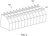
- Figure 2 is a schematic diagram of the body of the electrical control panel for connector terminals, the electrical control cabinet and the body of the connector terminals of the air conditioner.
- Figure 3 is a schematic diagram of a clamping block of the control panel for connector terminals, the electrical control cabinet and the air conditioner.
- Figure 4 is a schematic diagram, from another angle, of the clamping block of the control panel for connector terminals, the electrical control cabinet and the air conditioner.
- 100 motherboard body; 200, connector terminal body; 201, connection port; 202, control switch; 300, electrical control cabinet; 301, clamping slot; 302, sliding groove; 303, clamping block.
- the terms "linked”, “connected”, and “fixed” should be broadly interpreted. For example, it can be a fixed connection or a detachable connection, or it can form one integrated body. It can be a mechanical connection or an electrical connection. It can be direct linkage or indirectly through an intermediary element. It can be the internal linkage of two elements or an interactive relationship between two elements. For persons having ordinary skill in the art, the specific meaning of these terms in this invention can be understood based on the specific circumstances.
- first feature when a first feature is “above” or “below” a second feature, it can include direct contact between the first and second features, and it can also include the first and second feature not being in direct contact but being in contact through another feature between them.
- a first feature being “on top of', “on”, and “above” a second feature includes the first feature being directly above and diagonally above the second feature, or it merely indicates that the height of the first feature is higher than the second feature.
- the first feature being “beneath”, “under” and “below” the second feature includes the first feature being directly below and diagonally below the second feature, or it merely indicates that the height of the first feature is lower than the second feature.
- the sockets disposed on the motherboard body of a traditional air conditioner require extra terminal blocks matched to the sockets, and they require custom-made wiring sets to connect the sockets to the terminal blocks.
- the addition of terminal blocks means increased electrical control cabinet volume, which leads to additional costs.
- This invention replaces sockets connected to terminal blocks with a connector terminal body 200, and the control switch 202 can compress or loosen the conducting wire inserted into the connection port 201, reducing the number of hard connections, reducing the volume of the electrical control cabinet 300, lowering material costs, simplifying wiring, saving time, and reducing the cost of labor.
- Figure 1 is a schematic diagram of an electrical control panel for connector terminals, an electrical control cabinet 300 and the air conditioner
- Figure 2 is a schematic diagram of the connector terminal body 200 of the control panel for connector terminals, the electrical control cabinet 300 and the air conditioner body
- Figure 3 is a schematic diagram of the clamping block 303 of the control panel for connector terminals, the electrical control cabinet 300 and the air conditioner
- Figure 4 is a schematic diagram, from another angle, of the clamping block 303 of the control panel for connector terminals, the electrical control cabinet 300 and the air conditioner.
- this embodiment provides an electrical control panel for connector terminals, including:
- the preferred model of the connector terminal body 200 is HP-T6003, rated 300V, 8A; the diameter of the conducting wire inserted into the connection port 201 is 0.3 ⁇ 0.75mm; PA66 is used as the material of the connector terminal body 200.
- the connector terminal body 200 is soldered to the motherboard body 100, the connector terminal body 200 employs a base plate-style terminal block, the connection port 201 on the connector terminal body 200 corresponds to the control switch 202, the connector terminal body 200 has an in-use position and an idle position, when the control switch 202 is in the in-use position, the conducting wire inserted into the connection port 201 is in a compressed state, and when the control switch 202 is in the idle position, the conducting wire inserted into access the connection port 201 is in a loosened state.
- the connector terminal body 200 When the connector terminal body 200 is disposed axially or longitudinally along the motherboard body 100, and it is correspondingly connected to the components on the motherboard body 100, it can be understood that compared to having sockets on a traditional motherboard body 100, wherein the sockets must be equipped with matching terminal blocks, the connector terminal is characterized by reducing the number of hard connections, reducing the size of the electrical control cabinet 300, lowering material costs, simplifying wiring, saving time, and reducing the cost of labor.
- a strong current area and/or weak current area are disposed on the motherboard body 100, and if both the strong current area and the weak current area are present, the strong current area and the weak current area are spaced apart, and the strong current area and the weak current area each has a connector terminal body 200.
- maximizing the distance between the strong current area and the weak current area can achieve the separation of the strong current area and the weak current area connected to the motherboard body 100, thereby avoiding signal interference, improving the stability of the air conditioner's operation, and eliminating safety hazards.
- a strong current wire terminal is disposed on the strong current area
- a weak current wire terminal is disposed on the weak current area.
- the strong current area has other components such as relays
- the weak current area has circuits or components such as communication circuits
- the strong current wire terminal and weak current wire terminal have corresponding connector terminals; the strong current wire terminal and weak current wire terminal are spaced apart, to avoid interference between the strong and weak current elements and improve operational stability.
- control switch 202 on the connector terminal body 200 may be a lever-style switch, the connector terminal body 200 has an in-use position and an idle position, when the control switch 202 is in the in-use position, the wire inserted into the connector terminal is in a compressed state, and when the control switch 202 is in the idle position, the wire inserted into the connector terminal is in a loosened state
- the connector terminal body 200 must be able to withstand high temperatures in the preheating zone and temperatures conducted to the connector terminal body 200 through wave soldering throughout the entire assembly process; solder must not affect the connector terminal body 200, it must be easily removed, and there must be no residue.
- An electrical control cabinet 300 includes a cabinet body and the electrical control panel for connector terminals according to any of the above items; the cabinet body has a holding cavity, a plurality of clamping blocks are disposed on the inner wall of the holding cavity 303, and the plurality of clamping blocks 303 are distributed around the motherboard body 100 and are fitted with the motherboard body 100, such that the motherboard body 100 is connected to the cabinet body.
- the clamping blocks 303 are disposed on the inner walls of the side plates of the holding cavity. In this embodiment, there can be four clamping blocks 303, and the four clamping blocks 303 are positioned at the four corners of the motherboard body 100.
- clamping blocks 303 there can also be three clamping blocks 303, with the three clamping blocks 303 disposed around the motherboard body 100, and the clamping blocks 303 disposed at the side walls of the motherboard body 100.
- One clamping block 303 can be disposed at the middle of the upper end of the motherboard body 100, and two clamping blocks 303 can be disposed at the lower end of the motherboard body 100.
- the distance between the clamping block 303 located at the upper end of the motherboard body 100 and the clamping blocks 303 located at the lower end of the motherboard body 100 is not greater than the distance between the upper and lower ends of the motherboard body 100, ensuring that the clamping block 303 can clamp the motherboard body 100 inside the electrical control cabinet 300.
- the clamping blocks 303 include a first clamping block and a second clamping block located at opposite ends of the motherboard body 100, the clamping blocks 303 have clamping slots 301, and the side walls of the motherboard body 100 are clamped inside the clamping slots 301.
- the first clamping block and the second clamping block both have a clamping slot 301, the clamping slot 301 is U-shaped, and the opening of the clamping slot 301 is disposed in the direction of the side wall of the motherboard body 100.
- the radius of the opening of the clamping slot 301 is not less than the thickness of the motherboard body 100, and when the motherboard body 100 is disposed within the clamping slot 301, there is a certain space between the motherboard body 100 and the inner walls of the electrical control cabinet 300, ensuring the safe use of the motherboard body 100 and anti-interference capability.
- sliding grooves 302 are disposed on the inner wall of the holding cavity, the sliding grooves 302 are distributed along the axis of the holding cavity, and the first clamping block is slidably connected inside the sliding grooves 302.
- the number of sliding grooves 302 is set as needed, and there can be one or two.
- two sliding grooves 302 are employed, and the two sliding grooves 302 located on the same side of the motherboard body 100 are positioned on the same horizontal line.
- clamping blocks 303 located on the same side of the motherboard body 100 are both positioned on the same horizontal line, such that when the motherboard body 100 is disposed within the clamping slots 301, it will not tilt.
- springs are disposed within the sliding grooves 302, and the ends of the springs are connected to the sliding grooves (302) and the first clamping block.
- the springs when there are springs between the sliding grooves 302 and the first clamping block, the springs are in their original state or a slightly compressed state. In a more advantageous scheme, when there are springs between the sliding grooves 302 and the first clamping block, the springs are in a slightly compressed state, which can more tightly clamp the motherboard body 100.
- An air conditioner includes:
- the reference terms "one embodiment” and “example” mean that a specific characteristic, structure, material, or feature described by the embodiment or example is contained within at least one embodiment or example of this invention. In this Specification, illustrative expressions of these terms do not necessarily refer to the same embodiment or example.
Landscapes
- Engineering & Computer Science (AREA)
- Chemical & Material Sciences (AREA)
- Combustion & Propulsion (AREA)
- Mechanical Engineering (AREA)
- General Engineering & Computer Science (AREA)
- Microelectronics & Electronic Packaging (AREA)
- Air Filters, Heat-Exchange Apparatuses, And Housings Of Air-Conditioning Units (AREA)
Description
- The present invention relates to the technical field of air conditioning systems, and in particular to an electrical control panel for connector terminals, an electrical control cabinet, and an air conditioner.
- Air conditioning, or air conditioners, refer to devices regulating and controlling parameters such as the temperature, humidity, and flow of the air in a building or structure by man-made means.
- Air conditioners are composed of four parts: a cooling system, an air duct system, an electrical system, and a cabinet and a panel. The cooling system is the refrigeration and cooling part of the air conditioner, and it is a sealed refrigeration cycle composed of a refrigeration compressor, a condenser, capillary tubes, an evaporator, a solenoid directional valve, a filter, and refrigerant. The air duct system is the part of the air conditioner that accelerates the heat exchange of air, and it is composed of devices such as a centrifugal blower and an axial flow fan. The electrical system is the part in the air conditioner that controls the temperature and causes the compressor and fan to operate safely, and it is composed of a motor, a thermostat, a relay, a capacitor, and a heater. The cabinet and panel are the air conditioner's framework, various components and supports, and parts directing the airflow, and they are composed of a cabinet, a panel, and louvers.
- However, the sockets disposed on the motherboard body of a traditional air conditioner require providing extra terminal blocks matched to the sockets, and they require custom-made wiring sets to connect the sockets to the terminal blocks. The addition of terminal blocks means increased electrical control cabinet volume, which leads to additional costs.
- An objective of at least the example embodiments of this invention is: to provide an electrical control panel for connector terminals, an electrical control cabinet, and an air conditioner, with the aim of resolving the problem of the sockets disposed on the motherboard body of traditional air conditioners requiring the addition of extra terminal blocks and requiring custom-made wiring sets, increasing electrical control cabinet volume and thereby increasing costs. The invention is defined by the subject-matter of
claim 1. - According to the invention, there is provided an electrical control cabinet including a cabinet body and an electrical control panel according to the subject-matter of
claim 1. - Optionally, a strong current area and/or weak current area are disposed on the motherboard body, and if the strong current area and the weak current area are simultaneously present, the strong current area and the weak current area are spaced apart, and the strong current area and the weak current area each have a connector terminal body.
- Optionally, a strong current wire terminal is disposed on the strong current area, and a weak current wire terminal is disposed on the weak current area.
- Optionally, the control switches on the connector terminal body may be lever-style switches, the connector terminal body has an in-use position and an idle position, when the control switches are in the in-use position, the wires inserted into the connector terminal are in a compressed state, and when the control switches are in the idle position, the wires inserted into the connector terminal are in a loosened state.
- Optionally, springs are disposed within the sliding grooves, and the ends of the spring are connected to the sliding groove and the first clamping block.
- According to a third aspect, an air conditioner is provided according to the subject-matter of
claim 6. - Prior art document
GB2164803A - Compared to prior art, the benefits of this invention are: a connector terminal body is disposed on the motherboard body of this invention, and the control switch can compress or loosen the conducting wire inserted into the connection port, reducing the number of hard connections, reducing the volume of the electrical control cabinet, lowering material costs, simplifying wiring, saving time, and reducing the cost of labor.
- In the above discussion, weak current may be electricity meeting certain safety criteria. The references to weak current may be understood to define electricity used for information transmission. This is in contrast to strong current, which may for example be electricity used for power transmission. Weak current may be DC, and/or may be below 24 volts. Strong current may be AC and/or may be 100 volts or higher.
- The following is a more detailed exemplary description of this invention provided by way of example only, based on the drawings and embodiments.
-
Figure 1 is a schematic diagram of an electrical control panel for connector terminals, an electrical control cabinet and an air conditioner. -
Figure 2 is a schematic diagram of the body of the electrical control panel for connector terminals, the electrical control cabinet and the body of the connector terminals of the air conditioner. -
Figure 3 is a schematic diagram of a clamping block of the control panel for connector terminals, the electrical control cabinet and the air conditioner. -
Figure 4 is a schematic diagram, from another angle, of the clamping block of the control panel for connector terminals, the electrical control cabinet and the air conditioner. - In the figures:
100, motherboard body; 200, connector terminal body; 201, connection port; 202, control switch; 300, electrical control cabinet; 301, clamping slot; 302, sliding groove; 303, clamping block. - In order to clarify the technical problem addressed, the technical schemes employed, and the technical effects achieved by this invention, the technical schemes of the embodiments of this invention are described in further detail below. Clearly, the embodiments described are merely a portion of the embodiments of this invention, and are not all of the embodiments. All other embodiments based on the claims of this invention and obtained by a person skilled in the art without the expenditure of creative labor shall fall within the scope of protection of this invention as defined by the claims.
- In the descriptions of this invention, unless otherwise explicitly stipulated and defined, the terms "linked", "connected", and "fixed" should be broadly interpreted. For example, it can be a fixed connection or a detachable connection, or it can form one integrated body. It can be a mechanical connection or an electrical connection. It can be direct linkage or indirectly through an intermediary element. It can be the internal linkage of two elements or an interactive relationship between two elements. For persons having ordinary skill in the art, the specific meaning of these terms in this invention can be understood based on the specific circumstances.
- In this invention, unless otherwise explicitly stipulated and defined, when a first feature is "above" or "below" a second feature, it can include direct contact between the first and second features, and it can also include the first and second feature not being in direct contact but being in contact through another feature between them. Also, a first feature being "on top of', "on", and "above" a second feature includes the first feature being directly above and diagonally above the second feature, or it merely indicates that the height of the first feature is higher than the second feature. The first feature being "beneath", "under" and "below" the second feature includes the first feature being directly below and diagonally below the second feature, or it merely indicates that the height of the first feature is lower than the second feature.
- The sockets disposed on the motherboard body of a traditional air conditioner require extra terminal blocks matched to the sockets, and they require custom-made wiring sets to connect the sockets to the terminal blocks. The addition of terminal blocks means increased electrical control cabinet volume, which leads to additional costs.
- This invention replaces sockets connected to terminal blocks with a connector
terminal body 200, and thecontrol switch 202 can compress or loosen the conducting wire inserted into theconnection port 201, reducing the number of hard connections, reducing the volume of theelectrical control cabinet 300, lowering material costs, simplifying wiring, saving time, and reducing the cost of labor. - In this invention,
Figure 1 is a schematic diagram of an electrical control panel for connector terminals, anelectrical control cabinet 300 and the air conditioner;Figure 2 is a schematic diagram of theconnector terminal body 200 of the control panel for connector terminals, theelectrical control cabinet 300 and the air conditioner body;Figure 3 is a schematic diagram of theclamping block 303 of the control panel for connector terminals, theelectrical control cabinet 300 and the air conditioner;Figure 4 is a schematic diagram, from another angle, of theclamping block 303 of the control panel for connector terminals, theelectrical control cabinet 300 and the air conditioner. - As shown in
Figure 1 , this embodiment provides an electrical control panel for connector terminals, including: - a
motherboard body 100; - a
connector terminal body 200, wherein theconnector terminal body 200 is disposed on themotherboard body 100, there is at least oneconnector terminal body 200, a plurality ofconnection ports 201 andcontrol switches 202 corresponding to theconnection ports 201 are disposed on theconnector terminal body 200, theconnection ports 201 are connected to the components of themotherboard body 100, and thecontrol switches 202 act to compress or loosen conducting wires. - In this invention, the preferred model of the
connector terminal body 200 is HP-T6003, rated 300V, 8A; the diameter of the conducting wire inserted into theconnection port 201 is 0.3~0.75mm; PA66 is used as the material of theconnector terminal body 200. - It can be understood that the connector
terminal body 200 is soldered to themotherboard body 100, theconnector terminal body 200 employs a base plate-style terminal block, theconnection port 201 on theconnector terminal body 200 corresponds to thecontrol switch 202, theconnector terminal body 200 has an in-use position and an idle position, when thecontrol switch 202 is in the in-use position, the conducting wire inserted into theconnection port 201 is in a compressed state, and when thecontrol switch 202 is in the idle position, the conducting wire inserted into access theconnection port 201 is in a loosened state. - When the connector
terminal body 200 is disposed axially or longitudinally along themotherboard body 100, and it is correspondingly connected to the components on themotherboard body 100, it can be understood that compared to having sockets on atraditional motherboard body 100, wherein the sockets must be equipped with matching terminal blocks, the connector terminal is characterized by reducing the number of hard connections, reducing the size of theelectrical control cabinet 300, lowering material costs, simplifying wiring, saving time, and reducing the cost of labor. - In this invention, a strong current area and/or weak current area are disposed on the
motherboard body 100, and if both the strong current area and the weak current area are present, the strong current area and the weak current area are spaced apart, and the strong current area and the weak current area each has aconnector terminal body 200. - When a strong current area and a weak current area are disposed on the
motherboard body 100, maximizing the distance between the strong current area and the weak current area can achieve the separation of the strong current area and the weak current area connected to themotherboard body 100, thereby avoiding signal interference, improving the stability of the air conditioner's operation, and eliminating safety hazards. - Furthermore, a strong current wire terminal is disposed on the strong current area, and a weak current wire terminal is disposed on the weak current area.
- Specifically, the strong current area has other components such as relays, the weak current area has circuits or components such as communication circuits, and the strong current wire terminal and weak current wire terminal have corresponding connector terminals; the strong current wire terminal and weak current wire terminal are spaced apart, to avoid interference between the strong and weak current elements and improve operational stability.
- Here, the
control switch 202 on theconnector terminal body 200 may be a lever-style switch, theconnector terminal body 200 has an in-use position and an idle position, when thecontrol switch 202 is in the in-use position, the wire inserted into the connector terminal is in a compressed state, and when thecontrol switch 202 is in the idle position, the wire inserted into the connector terminal is in a loosened state - It can be understood that the
connector terminal body 200 must be able to withstand high temperatures in the preheating zone and temperatures conducted to theconnector terminal body 200 through wave soldering throughout the entire assembly process; solder must not affect theconnector terminal body 200, it must be easily removed, and there must be no residue. - An
electrical control cabinet 300 includes a cabinet body and the electrical control panel for connector terminals according to any of the above items; the cabinet body has a holding cavity, a plurality of clamping blocks are disposed on the inner wall of theholding cavity 303, and the plurality ofclamping blocks 303 are distributed around themotherboard body 100 and are fitted with themotherboard body 100, such that themotherboard body 100 is connected to the cabinet body. - The
clamping blocks 303 are disposed on the inner walls of the side plates of the holding cavity. In this embodiment, there can be fourclamping blocks 303, and the fourclamping blocks 303 are positioned at the four corners of themotherboard body 100. - It can be understood that there can also be three
clamping blocks 303, with the threeclamping blocks 303 disposed around themotherboard body 100, and theclamping blocks 303 disposed at the side walls of themotherboard body 100. Oneclamping block 303 can be disposed at the middle of the upper end of themotherboard body 100, and twoclamping blocks 303 can be disposed at the lower end of themotherboard body 100. - The distance between the
clamping block 303 located at the upper end of themotherboard body 100 and theclamping blocks 303 located at the lower end of themotherboard body 100 is not greater than the distance between the upper and lower ends of themotherboard body 100, ensuring that theclamping block 303 can clamp themotherboard body 100 inside theelectrical control cabinet 300. - Furthermore, the clamping blocks 303 include a first clamping block and a second clamping block located at opposite ends of the
motherboard body 100, the clamping blocks 303 have clampingslots 301, and the side walls of themotherboard body 100 are clamped inside the clampingslots 301. - Specifically, the first clamping block and the second clamping block both have a
clamping slot 301, theclamping slot 301 is U-shaped, and the opening of theclamping slot 301 is disposed in the direction of the side wall of themotherboard body 100. - The radius of the opening of the
clamping slot 301 is not less than the thickness of themotherboard body 100, and when themotherboard body 100 is disposed within theclamping slot 301, there is a certain space between themotherboard body 100 and the inner walls of theelectrical control cabinet 300, ensuring the safe use of themotherboard body 100 and anti-interference capability. - In this invention, sliding
grooves 302 are disposed on the inner wall of the holding cavity, the slidinggrooves 302 are distributed along the axis of the holding cavity, and the first clamping block is slidably connected inside the slidinggrooves 302. - As shown in
Figure 3 , the number of slidinggrooves 302 is set as needed, and there can be one or two. In this embodiment, two slidinggrooves 302 are employed, and the two slidinggrooves 302 located on the same side of themotherboard body 100 are positioned on the same horizontal line. - It can be understood that the clamping blocks 303 located on the same side of the
motherboard body 100 are both positioned on the same horizontal line, such that when themotherboard body 100 is disposed within the clampingslots 301, it will not tilt. - Furthermore, springs are disposed within the sliding
grooves 302, and the ends of the springs are connected to the sliding grooves (302) and the first clamping block. - Specifically, when there are springs between the sliding
grooves 302 and the first clamping block, the springs are in their original state or a slightly compressed state. In a more advantageous scheme, when there are springs between the slidinggrooves 302 and the first clamping block, the springs are in a slightly compressed state, which can more tightly clamp themotherboard body 100. - An air conditioner, includes:
- a plurality of connector terminal electrical control panels according to any of the above items, and;
- a plurality of
electrical control cabinets 300 according to any of the above items. - In the descriptions herein, it must be understood that terms of an orientational or positional relationship such as "above", "below", "left", and "right" are used solely to facilitate description and simplify operation, and do not indicate or imply that the referenced equipment or elements must have a specific orientation or be constructed and operated at a specific orientation; therefore, they must not be interpreted as limiting this invention. In addition, the terms "first" and "second" are merely used to provide descriptive differentiation and have no special implications.
- In the descriptions of this Specification, the reference terms "one embodiment" and "example" mean that a specific characteristic, structure, material, or feature described by the embodiment or example is contained within at least one embodiment or example of this invention. In this Specification, illustrative expressions of these terms do not necessarily refer to the same embodiment or example.
- In addition, it should be understood that, even though this Specification provides descriptions by means of implementation, it is not the case that every implementation contains only one independent technical scheme. This narrative form of the Specification is merely for the sake of clarity. A person skilled in the art should take the Specification as a whole. The technical schemes in the various embodiments may be appropriately combined, to form other implementations understandable to a person skilled in the art.
- In combination with specific embodiments, the above describes the technical principles of this invention. These descriptions are solely for the purpose of explaining the principles of this invention, and must not, by any means, be interpreted as limiting the scope of protection of this invention. The scope of protection of this invention is defined by the claims.
Claims (6)
- An electrical control cabinet (300) comprising a cabinet body and an electrical control panel for connector terminals, wherein the electrical control panel for connector terminals comprises:a motherboard body (100); anda connector terminal body (200), wherein the connector terminal body (200) is disposed on the motherboard body (100), wherein there is at least one connector terminal body (200), wherein a plurality of connection ports (201) and control switches (202) corresponding to the connection ports (201) are disposed on the connector terminal body (200), the connection ports (201) are connected to components of the motherboard body (100), and the control switches (202) act to compress or loosen conducting wires;characterized in thatthe cabinet body has a holding cavity, a plurality of clamping blocks (303) are disposed on an inner wall of the holding cavity, and the plurality of clamping blocks are distributed around the motherboard body (100) and are fitted with the motherboard body (100) such that the motherboard body (100) is connected to the cabinet body; andwherein the clamping blocks (303) comprise a first clamping block and a second clamping block located at opposite ends of the motherboard body (100), the clamping blocks (303) have clamping slots (301), and side walls of the motherboard body (100) are clamped inside the clamping slots (301);whereinsliding grooves (302) are disposed on the inner wall of the holding cavity, the sliding grooves (302) are distributed along an axis of the holding cavity, and the first clamping block (303) is slidably connected inside the sliding grooves (302).
- The electrical control cabinet according to claim 1, wherein a strong current area and/or a weak current area are disposed on the motherboard body (100), and if both the strong current area and the weak current area are present, the strong current area and the weak current area are spaced apart, and the strong current area and the weak current area each has a connector terminal body (200).
- The electrical control cabinet according to claim 2, wherein a strong current wire terminal is disposed on the strong current area, and a weak current wire terminal is disposed on the weak current area.
- The electrical control cabinet according to any of claims 1-3, wherein the control switches (202) on the connector terminal body (200) may be lever-style switches, the connector terminal body (200) has an in-use position and an idle position, when the control switches (202) are in the in-use position, the wires inserted into the connector terminal (201) are in a compressed state, and when the control switches (202) are in the idle position, the wires inserted into the connector terminal (201) are in a loosened state.
- The electrical control cabinet (300) according to any preceding claim, wherein springs are disposed within the sliding grooves (302), and the ends of the springs are connected to the sliding grooves (302) and the first clamping block (303).
- An air conditioner, comprising:
a plurality of electrical control cabinets (300) according to any preceding claim.
Applications Claiming Priority (1)
| Application Number | Priority Date | Filing Date | Title |
|---|---|---|---|
| CN202022395633.0U CN213991163U (en) | 2020-10-23 | 2020-10-23 | Binding post's automatically controlled board, electric cabinet and air conditioner |
Publications (3)
| Publication Number | Publication Date |
|---|---|
| EP3989366A2 EP3989366A2 (en) | 2022-04-27 |
| EP3989366A3 EP3989366A3 (en) | 2022-08-24 |
| EP3989366B1 true EP3989366B1 (en) | 2024-11-27 |
Family
ID=77258777
Family Applications (1)
| Application Number | Title | Priority Date | Filing Date |
|---|---|---|---|
| EP21202222.2A Active EP3989366B1 (en) | 2020-10-23 | 2021-10-12 | Electrical control panel for connector terminals, electrical control cabinet, and air conditioner |
Country Status (3)
| Country | Link |
|---|---|
| US (1) | US20220131288A1 (en) |
| EP (1) | EP3989366B1 (en) |
| CN (1) | CN213991163U (en) |
Family Cites Families (10)
| Publication number | Priority date | Publication date | Assignee | Title |
|---|---|---|---|---|
| GB8423575D0 (en) * | 1984-09-18 | 1984-10-24 | Smiths Ind Plc Ac | Electrical equipment housings/clamping means |
| US4759726A (en) * | 1985-08-13 | 1988-07-26 | Reed Devices, Inc. | Screwless type electrical terminal block |
| FI101121B (en) * | 1993-09-24 | 1998-04-15 | Fibox Oy Ab | Circuit card holder for electronics, electrical and appliance installation boxes |
| US20040217182A1 (en) * | 2003-04-29 | 2004-11-04 | Texas Instruments Incorporated | Integrated furnace control board and method |
| KR100600589B1 (en) * | 2005-07-29 | 2006-07-13 | 삼성전자주식회사 | Circuit board fixing device of air conditioner |
| US20080299534A1 (en) * | 2007-05-31 | 2008-12-04 | Jesse Richardson | Training apparatus for servicing domestic appliances |
| CN101730383B (en) * | 2008-10-23 | 2012-03-14 | 鸿富锦精密工业(深圳)有限公司 | Printed circuit board |
| JP5123975B2 (en) * | 2010-04-08 | 2013-01-23 | パナソニック株式会社 | connector |
| KR101992147B1 (en) * | 2012-10-26 | 2019-09-30 | 삼성전자주식회사 | Air conditioner |
| CN113366693B (en) * | 2018-09-27 | 2024-01-19 | Cps 科技控股有限公司 | Mounting clips for printed circuit boards |
-
2020
- 2020-10-23 CN CN202022395633.0U patent/CN213991163U/en active Active
-
2021
- 2021-10-12 EP EP21202222.2A patent/EP3989366B1/en active Active
- 2021-10-21 US US17/506,810 patent/US20220131288A1/en not_active Abandoned
Also Published As
| Publication number | Publication date |
|---|---|
| EP3989366A3 (en) | 2022-08-24 |
| CN213991163U (en) | 2021-08-17 |
| EP3989366A2 (en) | 2022-04-27 |
| US20220131288A1 (en) | 2022-04-28 |
Similar Documents
| Publication | Publication Date | Title |
|---|---|---|
| EP2860463A1 (en) | Refrigeration device | |
| KR20100046392A (en) | Air conditioner | |
| US6606871B2 (en) | Twinning interface control box kit for twinned fan coils in dual heat pump or AC system | |
| US20030042010A1 (en) | Wire fixing structure, electrical equipment mount device and air conditioner using the same | |
| CN105814374A (en) | refrigeration unit | |
| EP3989366A2 (en) | Electrical control panel for connector terminals, electrical control cabinet, and air conditioner | |
| EP3101361B1 (en) | Electric equipment housing | |
| US11162692B2 (en) | Fan assembly for an HVAC unit | |
| EP4671630A1 (en) | OUTDOOR AIR CONDITIONING UNIT | |
| US20210333024A1 (en) | System and method of cooling of heat generating units in an hvac unit | |
| JP3086623B2 (en) | Air conditioner | |
| US11641079B2 (en) | Mistake-proof electrical connectors for HVAC systems | |
| TWI871617B (en) | Air Conditioner | |
| KR0118096Y1 (en) | Airconditioner | |
| US10830482B2 (en) | HVAC cable grounding systems and methods | |
| US5173843A (en) | Fan control and diode interlock for electric heaters | |
| CN223258348U (en) | Air conditioner | |
| WO2023209838A1 (en) | Air conditioner | |
| CN218328403U (en) | Composite air disc purifying device | |
| US11976828B2 (en) | Outdoor unit of air-conditioning apparatus | |
| EP4600571A1 (en) | Outdoor unit for air conditioner | |
| CN109659991A (en) | A kind of combined DC charging system based on phase transformation heat exchange | |
| KR100291738B1 (en) | Apparatus for changing the amount of the wind from duct in air conditioner | |
| KR200248030Y1 (en) | Switching control circuit of multi air conditioner | |
| KR200154608Y1 (en) | Wire connection device of air conditioner |
Legal Events
| Date | Code | Title | Description |
|---|---|---|---|
| PUAI | Public reference made under article 153(3) epc to a published international application that has entered the european phase |
Free format text: ORIGINAL CODE: 0009012 |
|
| STAA | Information on the status of an ep patent application or granted ep patent |
Free format text: STATUS: THE APPLICATION HAS BEEN PUBLISHED |
|
| AK | Designated contracting states |
Kind code of ref document: A2 Designated state(s): AL AT BE BG CH CY CZ DE DK EE ES FI FR GB GR HR HU IE IS IT LI LT LU LV MC MK MT NL NO PL PT RO RS SE SI SK SM TR |
|
| PUAL | Search report despatched |
Free format text: ORIGINAL CODE: 0009013 |
|
| AK | Designated contracting states |
Kind code of ref document: A3 Designated state(s): AL AT BE BG CH CY CZ DE DK EE ES FI FR GB GR HR HU IE IS IT LI LT LU LV MC MK MT NL NO PL PT RO RS SE SI SK SM TR |
|
| RIC1 | Information provided on ipc code assigned before grant |
Ipc: H05K 7/14 20060101ALI20220719BHEP Ipc: H05K 1/18 20060101ALI20220719BHEP Ipc: H01R 12/51 20110101AFI20220719BHEP |
|
| STAA | Information on the status of an ep patent application or granted ep patent |
Free format text: STATUS: REQUEST FOR EXAMINATION WAS MADE |
|
| 17P | Request for examination filed |
Effective date: 20230224 |
|
| RBV | Designated contracting states (corrected) |
Designated state(s): AL AT BE BG CH CY CZ DE DK EE ES FI FR GB GR HR HU IE IS IT LI LT LU LV MC MK MT NL NO PL PT RO RS SE SI SK SM TR |
|
| REG | Reference to a national code |
Ref country code: DE Ref legal event code: R079 Ref document number: 602021022333 Country of ref document: DE Free format text: PREVIOUS MAIN CLASS: H01R0012510000 Ipc: H05K0003340000 |
|
| GRAP | Despatch of communication of intention to grant a patent |
Free format text: ORIGINAL CODE: EPIDOSNIGR1 |
|
| STAA | Information on the status of an ep patent application or granted ep patent |
Free format text: STATUS: GRANT OF PATENT IS INTENDED |
|
| RIC1 | Information provided on ipc code assigned before grant |
Ipc: H05K 3/34 20060101AFI20240624BHEP |
|
| INTG | Intention to grant announced |
Effective date: 20240712 |
|
| GRAS | Grant fee paid |
Free format text: ORIGINAL CODE: EPIDOSNIGR3 |
|
| GRAA | (expected) grant |
Free format text: ORIGINAL CODE: 0009210 |
|
| STAA | Information on the status of an ep patent application or granted ep patent |
Free format text: STATUS: THE PATENT HAS BEEN GRANTED |
|
| AK | Designated contracting states |
Kind code of ref document: B1 Designated state(s): AL AT BE BG CH CY CZ DE DK EE ES FI FR GB GR HR HU IE IS IT LI LT LU LV MC MK MT NL NO PL PT RO RS SE SI SK SM TR |
|
| REG | Reference to a national code |
Ref country code: GB Ref legal event code: FG4D |
|
| REG | Reference to a national code |
Ref country code: CH Ref legal event code: EP |
|
| REG | Reference to a national code |
Ref country code: IE Ref legal event code: FG4D |
|
| REG | Reference to a national code |
Ref country code: DE Ref legal event code: R096 Ref document number: 602021022333 Country of ref document: DE |
|
| REG | Reference to a national code |
Ref country code: LT Ref legal event code: MG9D |
|
| REG | Reference to a national code |
Ref country code: NL Ref legal event code: MP Effective date: 20241127 |
|
| PG25 | Lapsed in a contracting state [announced via postgrant information from national office to epo] |
Ref country code: IS Free format text: LAPSE BECAUSE OF FAILURE TO SUBMIT A TRANSLATION OF THE DESCRIPTION OR TO PAY THE FEE WITHIN THE PRESCRIBED TIME-LIMIT Effective date: 20250327 Ref country code: PT Free format text: LAPSE BECAUSE OF FAILURE TO SUBMIT A TRANSLATION OF THE DESCRIPTION OR TO PAY THE FEE WITHIN THE PRESCRIBED TIME-LIMIT Effective date: 20250327 Ref country code: HR Free format text: LAPSE BECAUSE OF FAILURE TO SUBMIT A TRANSLATION OF THE DESCRIPTION OR TO PAY THE FEE WITHIN THE PRESCRIBED TIME-LIMIT Effective date: 20241127 |
|
| PG25 | Lapsed in a contracting state [announced via postgrant information from national office to epo] |
Ref country code: FI Free format text: LAPSE BECAUSE OF FAILURE TO SUBMIT A TRANSLATION OF THE DESCRIPTION OR TO PAY THE FEE WITHIN THE PRESCRIBED TIME-LIMIT Effective date: 20241127 Ref country code: NL Free format text: LAPSE BECAUSE OF FAILURE TO SUBMIT A TRANSLATION OF THE DESCRIPTION OR TO PAY THE FEE WITHIN THE PRESCRIBED TIME-LIMIT Effective date: 20241127 |
|
| REG | Reference to a national code |
Ref country code: AT Ref legal event code: MK05 Ref document number: 1747032 Country of ref document: AT Kind code of ref document: T Effective date: 20241127 |
|
| PG25 | Lapsed in a contracting state [announced via postgrant information from national office to epo] |
Ref country code: BG Free format text: LAPSE BECAUSE OF FAILURE TO SUBMIT A TRANSLATION OF THE DESCRIPTION OR TO PAY THE FEE WITHIN THE PRESCRIBED TIME-LIMIT Effective date: 20241127 |
|
| PG25 | Lapsed in a contracting state [announced via postgrant information from national office to epo] |
Ref country code: ES Free format text: LAPSE BECAUSE OF FAILURE TO SUBMIT A TRANSLATION OF THE DESCRIPTION OR TO PAY THE FEE WITHIN THE PRESCRIBED TIME-LIMIT Effective date: 20241127 |
|
| PG25 | Lapsed in a contracting state [announced via postgrant information from national office to epo] |
Ref country code: NO Free format text: LAPSE BECAUSE OF FAILURE TO SUBMIT A TRANSLATION OF THE DESCRIPTION OR TO PAY THE FEE WITHIN THE PRESCRIBED TIME-LIMIT Effective date: 20250227 |
|
| PG25 | Lapsed in a contracting state [announced via postgrant information from national office to epo] |
Ref country code: LV Free format text: LAPSE BECAUSE OF FAILURE TO SUBMIT A TRANSLATION OF THE DESCRIPTION OR TO PAY THE FEE WITHIN THE PRESCRIBED TIME-LIMIT Effective date: 20241127 Ref country code: GR Free format text: LAPSE BECAUSE OF FAILURE TO SUBMIT A TRANSLATION OF THE DESCRIPTION OR TO PAY THE FEE WITHIN THE PRESCRIBED TIME-LIMIT Effective date: 20250228 Ref country code: AT Free format text: LAPSE BECAUSE OF FAILURE TO SUBMIT A TRANSLATION OF THE DESCRIPTION OR TO PAY THE FEE WITHIN THE PRESCRIBED TIME-LIMIT Effective date: 20241127 |
|
| PG25 | Lapsed in a contracting state [announced via postgrant information from national office to epo] |
Ref country code: PL Free format text: LAPSE BECAUSE OF FAILURE TO SUBMIT A TRANSLATION OF THE DESCRIPTION OR TO PAY THE FEE WITHIN THE PRESCRIBED TIME-LIMIT Effective date: 20241127 |
|
| PG25 | Lapsed in a contracting state [announced via postgrant information from national office to epo] |
Ref country code: RS Free format text: LAPSE BECAUSE OF FAILURE TO SUBMIT A TRANSLATION OF THE DESCRIPTION OR TO PAY THE FEE WITHIN THE PRESCRIBED TIME-LIMIT Effective date: 20250227 |
|
| PG25 | Lapsed in a contracting state [announced via postgrant information from national office to epo] |
Ref country code: SM Free format text: LAPSE BECAUSE OF FAILURE TO SUBMIT A TRANSLATION OF THE DESCRIPTION OR TO PAY THE FEE WITHIN THE PRESCRIBED TIME-LIMIT Effective date: 20241127 |
|
| PG25 | Lapsed in a contracting state [announced via postgrant information from national office to epo] |
Ref country code: DK Free format text: LAPSE BECAUSE OF FAILURE TO SUBMIT A TRANSLATION OF THE DESCRIPTION OR TO PAY THE FEE WITHIN THE PRESCRIBED TIME-LIMIT Effective date: 20241127 |
|
| PG25 | Lapsed in a contracting state [announced via postgrant information from national office to epo] |
Ref country code: EE Free format text: LAPSE BECAUSE OF FAILURE TO SUBMIT A TRANSLATION OF THE DESCRIPTION OR TO PAY THE FEE WITHIN THE PRESCRIBED TIME-LIMIT Effective date: 20241127 |
|
| PG25 | Lapsed in a contracting state [announced via postgrant information from national office to epo] |
Ref country code: RO Free format text: LAPSE BECAUSE OF FAILURE TO SUBMIT A TRANSLATION OF THE DESCRIPTION OR TO PAY THE FEE WITHIN THE PRESCRIBED TIME-LIMIT Effective date: 20241127 |
|
| PG25 | Lapsed in a contracting state [announced via postgrant information from national office to epo] |
Ref country code: SK Free format text: LAPSE BECAUSE OF FAILURE TO SUBMIT A TRANSLATION OF THE DESCRIPTION OR TO PAY THE FEE WITHIN THE PRESCRIBED TIME-LIMIT Effective date: 20241127 |
|
| PG25 | Lapsed in a contracting state [announced via postgrant information from national office to epo] |
Ref country code: CZ Free format text: LAPSE BECAUSE OF FAILURE TO SUBMIT A TRANSLATION OF THE DESCRIPTION OR TO PAY THE FEE WITHIN THE PRESCRIBED TIME-LIMIT Effective date: 20241127 |
|
| PG25 | Lapsed in a contracting state [announced via postgrant information from national office to epo] |
Ref country code: IT Free format text: LAPSE BECAUSE OF FAILURE TO SUBMIT A TRANSLATION OF THE DESCRIPTION OR TO PAY THE FEE WITHIN THE PRESCRIBED TIME-LIMIT Effective date: 20241127 |
|
| REG | Reference to a national code |
Ref country code: DE Ref legal event code: R097 Ref document number: 602021022333 Country of ref document: DE |
|
| PG25 | Lapsed in a contracting state [announced via postgrant information from national office to epo] |
Ref country code: SE Free format text: LAPSE BECAUSE OF FAILURE TO SUBMIT A TRANSLATION OF THE DESCRIPTION OR TO PAY THE FEE WITHIN THE PRESCRIBED TIME-LIMIT Effective date: 20241127 |
|
| PLBE | No opposition filed within time limit |
Free format text: ORIGINAL CODE: 0009261 |
|
| STAA | Information on the status of an ep patent application or granted ep patent |
Free format text: STATUS: NO OPPOSITION FILED WITHIN TIME LIMIT |
|
| PGFP | Annual fee paid to national office [announced via postgrant information from national office to epo] |
Ref country code: FR Payment date: 20250925 Year of fee payment: 5 |
|
| 26N | No opposition filed |
Effective date: 20250828 |
|
| PGFP | Annual fee paid to national office [announced via postgrant information from national office to epo] |
Ref country code: DE Payment date: 20250923 Year of fee payment: 5 |