EP3989353A1 - Battery module comprising bus bar plate, battery pack comprising same, and electronic device - Google Patents
Battery module comprising bus bar plate, battery pack comprising same, and electronic device Download PDFInfo
- Publication number
- EP3989353A1 EP3989353A1 EP20869106.3A EP20869106A EP3989353A1 EP 3989353 A1 EP3989353 A1 EP 3989353A1 EP 20869106 A EP20869106 A EP 20869106A EP 3989353 A1 EP3989353 A1 EP 3989353A1
- Authority
- EP
- European Patent Office
- Prior art keywords
- fuse portion
- battery module
- electrode terminal
- negative electrode
- terminal
- Prior art date
- Legal status (The legal status is an assumption and is not a legal conclusion. Google has not performed a legal analysis and makes no representation as to the accuracy of the status listed.)
- Pending
Links
Images







Classifications
-
- H—ELECTRICITY
- H01—ELECTRIC ELEMENTS
- H01M—PROCESSES OR MEANS, e.g. BATTERIES, FOR THE DIRECT CONVERSION OF CHEMICAL ENERGY INTO ELECTRICAL ENERGY
- H01M50/00—Constructional details or processes of manufacture of the non-active parts of electrochemical cells other than fuel cells, e.g. hybrid cells
- H01M50/50—Current conducting connections for cells or batteries
- H01M50/502—Interconnectors for connecting terminals of adjacent batteries; Interconnectors for connecting cells outside a battery casing
-
- H—ELECTRICITY
- H01—ELECTRIC ELEMENTS
- H01M—PROCESSES OR MEANS, e.g. BATTERIES, FOR THE DIRECT CONVERSION OF CHEMICAL ENERGY INTO ELECTRICAL ENERGY
- H01M10/00—Secondary cells; Manufacture thereof
- H01M10/05—Accumulators with non-aqueous electrolyte
- H01M10/052—Li-accumulators
-
- H—ELECTRICITY
- H01—ELECTRIC ELEMENTS
- H01M—PROCESSES OR MEANS, e.g. BATTERIES, FOR THE DIRECT CONVERSION OF CHEMICAL ENERGY INTO ELECTRICAL ENERGY
- H01M50/00—Constructional details or processes of manufacture of the non-active parts of electrochemical cells other than fuel cells, e.g. hybrid cells
- H01M50/20—Mountings; Secondary casings or frames; Racks, modules or packs; Suspension devices; Shock absorbers; Transport or carrying devices; Holders
- H01M50/204—Racks, modules or packs for multiple batteries or multiple cells
- H01M50/207—Racks, modules or packs for multiple batteries or multiple cells characterised by their shape
- H01M50/213—Racks, modules or packs for multiple batteries or multiple cells characterised by their shape adapted for cells having curved cross-section, e.g. round or elliptic
-
- H—ELECTRICITY
- H01—ELECTRIC ELEMENTS
- H01M—PROCESSES OR MEANS, e.g. BATTERIES, FOR THE DIRECT CONVERSION OF CHEMICAL ENERGY INTO ELECTRICAL ENERGY
- H01M50/00—Constructional details or processes of manufacture of the non-active parts of electrochemical cells other than fuel cells, e.g. hybrid cells
- H01M50/30—Arrangements for facilitating escape of gases
-
- H—ELECTRICITY
- H01—ELECTRIC ELEMENTS
- H01M—PROCESSES OR MEANS, e.g. BATTERIES, FOR THE DIRECT CONVERSION OF CHEMICAL ENERGY INTO ELECTRICAL ENERGY
- H01M50/00—Constructional details or processes of manufacture of the non-active parts of electrochemical cells other than fuel cells, e.g. hybrid cells
- H01M50/30—Arrangements for facilitating escape of gases
- H01M50/342—Non-re-sealable arrangements
- H01M50/3425—Non-re-sealable arrangements in the form of rupturable membranes or weakened parts, e.g. pierced with the aid of a sharp member
-
- H—ELECTRICITY
- H01—ELECTRIC ELEMENTS
- H01M—PROCESSES OR MEANS, e.g. BATTERIES, FOR THE DIRECT CONVERSION OF CHEMICAL ENERGY INTO ELECTRICAL ENERGY
- H01M50/00—Constructional details or processes of manufacture of the non-active parts of electrochemical cells other than fuel cells, e.g. hybrid cells
- H01M50/50—Current conducting connections for cells or batteries
-
- H—ELECTRICITY
- H01—ELECTRIC ELEMENTS
- H01M—PROCESSES OR MEANS, e.g. BATTERIES, FOR THE DIRECT CONVERSION OF CHEMICAL ENERGY INTO ELECTRICAL ENERGY
- H01M50/00—Constructional details or processes of manufacture of the non-active parts of electrochemical cells other than fuel cells, e.g. hybrid cells
- H01M50/50—Current conducting connections for cells or batteries
- H01M50/502—Interconnectors for connecting terminals of adjacent batteries; Interconnectors for connecting cells outside a battery casing
- H01M50/507—Interconnectors for connecting terminals of adjacent batteries; Interconnectors for connecting cells outside a battery casing comprising an arrangement of two or more busbars within a container structure, e.g. busbar modules
-
- H—ELECTRICITY
- H01—ELECTRIC ELEMENTS
- H01M—PROCESSES OR MEANS, e.g. BATTERIES, FOR THE DIRECT CONVERSION OF CHEMICAL ENERGY INTO ELECTRICAL ENERGY
- H01M50/00—Constructional details or processes of manufacture of the non-active parts of electrochemical cells other than fuel cells, e.g. hybrid cells
- H01M50/50—Current conducting connections for cells or batteries
- H01M50/543—Terminals
- H01M50/552—Terminals characterised by their shape
- H01M50/559—Terminals adapted for cells having curved cross-section, e.g. round, elliptic or button cells
-
- H—ELECTRICITY
- H01—ELECTRIC ELEMENTS
- H01M—PROCESSES OR MEANS, e.g. BATTERIES, FOR THE DIRECT CONVERSION OF CHEMICAL ENERGY INTO ELECTRICAL ENERGY
- H01M50/00—Constructional details or processes of manufacture of the non-active parts of electrochemical cells other than fuel cells, e.g. hybrid cells
- H01M50/50—Current conducting connections for cells or batteries
- H01M50/572—Means for preventing undesired use or discharge
-
- H—ELECTRICITY
- H01—ELECTRIC ELEMENTS
- H01M—PROCESSES OR MEANS, e.g. BATTERIES, FOR THE DIRECT CONVERSION OF CHEMICAL ENERGY INTO ELECTRICAL ENERGY
- H01M50/00—Constructional details or processes of manufacture of the non-active parts of electrochemical cells other than fuel cells, e.g. hybrid cells
- H01M50/50—Current conducting connections for cells or batteries
- H01M50/572—Means for preventing undesired use or discharge
- H01M50/574—Devices or arrangements for the interruption of current
- H01M50/578—Devices or arrangements for the interruption of current in response to pressure
-
- H—ELECTRICITY
- H01—ELECTRIC ELEMENTS
- H01M—PROCESSES OR MEANS, e.g. BATTERIES, FOR THE DIRECT CONVERSION OF CHEMICAL ENERGY INTO ELECTRICAL ENERGY
- H01M50/00—Constructional details or processes of manufacture of the non-active parts of electrochemical cells other than fuel cells, e.g. hybrid cells
- H01M50/50—Current conducting connections for cells or batteries
- H01M50/572—Means for preventing undesired use or discharge
- H01M50/574—Devices or arrangements for the interruption of current
- H01M50/581—Devices or arrangements for the interruption of current in response to temperature
-
- H—ELECTRICITY
- H01—ELECTRIC ELEMENTS
- H01M—PROCESSES OR MEANS, e.g. BATTERIES, FOR THE DIRECT CONVERSION OF CHEMICAL ENERGY INTO ELECTRICAL ENERGY
- H01M50/00—Constructional details or processes of manufacture of the non-active parts of electrochemical cells other than fuel cells, e.g. hybrid cells
- H01M50/50—Current conducting connections for cells or batteries
- H01M50/572—Means for preventing undesired use or discharge
- H01M50/574—Devices or arrangements for the interruption of current
- H01M50/583—Devices or arrangements for the interruption of current in response to current, e.g. fuses
-
- H—ELECTRICITY
- H01—ELECTRIC ELEMENTS
- H01M—PROCESSES OR MEANS, e.g. BATTERIES, FOR THE DIRECT CONVERSION OF CHEMICAL ENERGY INTO ELECTRICAL ENERGY
- H01M2200/00—Safety devices for primary or secondary batteries
- H01M2200/10—Temperature sensitive devices
- H01M2200/103—Fuse
-
- H—ELECTRICITY
- H01—ELECTRIC ELEMENTS
- H01M—PROCESSES OR MEANS, e.g. BATTERIES, FOR THE DIRECT CONVERSION OF CHEMICAL ENERGY INTO ELECTRICAL ENERGY
- H01M2220/00—Batteries for particular applications
- H01M2220/20—Batteries in motive systems, e.g. vehicle, ship, plane
-
- Y—GENERAL TAGGING OF NEW TECHNOLOGICAL DEVELOPMENTS; GENERAL TAGGING OF CROSS-SECTIONAL TECHNOLOGIES SPANNING OVER SEVERAL SECTIONS OF THE IPC; TECHNICAL SUBJECTS COVERED BY FORMER USPC CROSS-REFERENCE ART COLLECTIONS [XRACs] AND DIGESTS
- Y02—TECHNOLOGIES OR APPLICATIONS FOR MITIGATION OR ADAPTATION AGAINST CLIMATE CHANGE
- Y02E—REDUCTION OF GREENHOUSE GAS [GHG] EMISSIONS, RELATED TO ENERGY GENERATION, TRANSMISSION OR DISTRIBUTION
- Y02E60/00—Enabling technologies; Technologies with a potential or indirect contribution to GHG emissions mitigation
- Y02E60/10—Energy storage using batteries
Definitions
- the present disclosure relates to a battery module comprising a busbar plate, a battery pack comprising the same and an electronic device, and more particularly, to a battery module comprising a busbar plate for fast electrical disconnecting in the event of abnormal behavior (a short circuit) of a cylindrical battery cell.
- a lithium secondary battery primarily uses a lithium-based oxide and a carbon material for a positive electrode active material and a negative electrode active material respectively. Additionally, the lithium secondary battery includes an electrode assembly including a positive electrode plate and a negative electrode plate respectively coated with the positive electrode active material and the negative electrode active material and a separator interposed between the positive electrode plate and the negative electrode plate, and a packaging or a battery case in which the electrode assembly is hermetically received together with an electrolyte solution.
- the lithium secondary battery may be classified into a can-type secondary battery in which the electrode assembly is embedded in a metal can and a pouch-type secondary battery in which the electrode assembly is embedded in a pouch of an aluminum laminate sheet, according to the shape of the battery case.
- the metal can in which the electrode assembly is embedded may be cylindrical.
- the can-type secondary battery may be used to form a battery module including a housing to receive a plurality of secondary batteries and a busbar configured to electrically connect the plurality of secondary batteries.
- the busbar provided in the battery module uses a material having high electrical resistance to increase the resistance welding performance with the electrode terminal.
- BMS battery management system
- the present disclosure is designed to solve the above-described problem, and therefore the present disclosure is directed to providing a battery module comprising a busbar plate for fast electrical disconnecting in the event of abnormal behavior (a short circuit) of a cylindrical battery cell.
- a battery module includes a plurality of cylindrical battery cells arranged in a horizontal direction, some cylindrical battery cells each having a positive electrode terminal and a negative electrode terminal formed on top and bottom, the remaining cylindrical battery cells each having a negative electrode terminal and a positive electrode terminal formed on top and bottom, and including a gas vent through which the positive electrode terminal or the negative electrode terminal is opened to discharge an internal gas when an internal pressure is equal to or higher than a predetermined pressure, and a busbar plate including a body portion disposed on or below the plurality of cylindrical battery cells, and having a plate shape extending in the horizontal direction to cover the plurality of cylindrical battery cells, the body portion having at least one connection opening that is open in a vertical direction in an area in contact with the positive electrode terminal or the negative electrode terminal, a positive electrode connection terminal extending from an edge of the connection opening and having the extended part in contact with the positive electrode terminal to electrically connect the plurality of cylindrical battery cells, and a negative electrode connection terminal extending from the edge of the connection
- the connection terminal in contact with the positive electrode terminal or the negative electrode terminal that is not opened by the gas vent may include a fuse portion configured to blow when a predetermined current or above flows from the cylindrical battery cell, the fuse portion having a bent structure that is bent in the horizontal direction at least once.
- connection terminal may further include a connection portion in direct contact with the positive electrode terminal or the negative electrode terminal of the cylindrical battery cell, and the fuse portion may extend in the horizontal direction from the inner edge of the connection opening and an end in the extended direction may be connected to one end of the connection portion.
- busbar plate may further include an electrically insulating first fixing member having one side connected to the inner edge of the connection opening and the other side connected to part of the connection portion to fix the connection portion.
- busbar plate may further include an electrically insulating second fixing member having one side connected to the edge of the connection opening and the other side connected to part of the fuse portion to fix the fuse portion.
- At least part of a portion of the second fixing member extending from the edge of the connection opening to the part of the fuse portion may have elasticity to pull the fuse portion by elastic recovery when the fuse portion blows.
- busbar plate may further include a thermal insulation member around an outer surface of the fuse portion.
- thermal insulation element may be separated into at least two.
- the thermal insulation element may include a discharge hole configured to discharge a melted part of the fuse portion.
- busbar plate may further include an electrically insulating reinforcement member around an outer surface of the fuse portion and is configured to melt at a predetermined temperature or above.
- At least part of the fuse portion having the reinforcement member may be bent in an arch shape.
- the battery module may further include a module housing having receiving portions with a plurality of hollows to receive the plurality of cylindrical battery cells arranged in rows and columns in the horizontal direction.
- the fuse portion of the connection terminal in contact with the positive electrode terminal or the negative electrode terminal of the cylindrical battery cell disposed at an inner position in the horizontal direction may have a larger width than the fuse portion of the connection terminal in contact with the positive electrode terminal or the negative electrode terminal of the cylindrical battery cell disposed at an outer position in the horizontal direction.
- bent structure may be bent in opposite directions at least twice.
- the body portion may further include an external terminal electrically connected to the plurality of cylindrical battery cells at least in an area in which the connection opening is not formed.
- connection terminal may include at least two fuse portions, the at least two fuse portions may be spaced a predetermined distance apart from each other, and the at least two fuse portions may have different horizontal widths.
- a battery pack according to the present disclosure may include at least one battery module.
- an electronic device may include the battery pack.
- the battery module of the present disclosure includes the fuse portion in the connection terminal in contact with the positive electrode terminal or the negative electrode terminal that is not opened by the gas vent among the positive electrode connection terminal and the negative electrode connection terminal, the fuse portion configured to blow when a predetermined current or above flows from the cylindrical battery cell, to electrically isolate a specific cylindrical battery cell from the busbar plate when the high current flows in the specific cylindrical battery cell due to a short circuit between the plurality of cylindrical battery cells in the battery module. That is, it is possible to prevent a fire or thermal runaway in the battery module through the fuse portion. Accordingly, it is possible to increase the safety of the battery module.
- the electrode terminal that is not opened by the gas vent is disposed closer to the electrode assembly than the electrode terminal that is opened by the gas vent, and thus effectively receives the internal heat of the cylindrical battery cell, and accordingly the fuse portion may blow faster and more easily by the internal heat of the cylindrical battery cell.
- the fuse portion has the bent structure that is bent in the horizontal direction at least once, so it is easy to achieve a longer current path in the same space. That is, when the fuse portion extends linearly, it is necessary to form a larger connection opening, which places a space limitation on the electrical connection of one busbar plate with a larger number of cylindrical battery cells in a predetermined space. Accordingly, the present disclosure remarkably reduces the space occupied by the fuse portion of the busbar plate, thereby achieving the compact battery module.
- the busbar plate further includes the electrically insulating first fixing member having one side connected to the inner edge of the connection opening and the other side connected to part of the connection portion to fix the connection portion, in order to reduce the vibration of the connection portion when the battery module continuously vibrates by an external force. Accordingly, it is possible to effectively reduce the risk that the fuse portion may be cut or damaged by the continuous vibration.
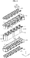
- FIG. 1 is a schematic perspective view of a battery module according to an embodiment of the present disclosure.
- FIG. 2 is a schematic exploded perspective view of the battery module according to an embodiment of the present disclosure.
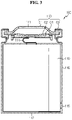
- FIG. 3 is a schematic cross-sectional view of a cylindrical battery cell of the battery module according to an embodiment of the present disclosure.
- the battery module 200 may include a plurality of cylindrical battery cells 100, a module housing 210 and a plurality of busbar plates 220.
- the cylindrical battery cell 100 may include a cylindrical battery can 116 and an electrode assembly (not shown) received in the battery can 116.
- the battery can 116 may include a material having high electrical conductivity, and for example, the battery can 116 may include aluminum or copper.
- the battery can 116 may be configured to stand upright in the vertical direction.
- the battery can 116 may be a cylindrical shape extending in the vertical direction.
- the electrode terminals 111, 112 may be formed on top and bottom of the battery can 116 respectively.
- the positive electrode terminal 111 may be formed on the flat circular upper surface on top of the battery can 116
- the negative electrode terminal 112 may be formed on the flat circular lower surface on bottom of the battery can 116.
- the plurality of cylindrical battery cells 100 may be arranged in rows and columns in the horizontal direction.
- the horizontal direction refers to a direction parallel to the ground when the cylindrical battery cell 100 is placed on the ground, and may be at least one direction on the plane perpendicular to the vertical direction.
- the horizontal direction may be X and Y directions of FIG. 2 .
- the battery module 200 includes 36 cylindrical battery cells 100 arranged in 3 rows in the front-rear direction (y direction in FIG. 2 ) and 12 columns in in the left-right direction (x direction).
- 18 cylindrical battery cells may have the positive electrode terminal 111 and the negative electrode terminal 112 disposed on top and bottom respectively, and the remaining 18 cylindrical battery cells may have the negative electrode terminal 112 and the positive electrode terminal 111 disposed on top and bottom respectively.
- the cylindrical battery cell 100 may include an electrode assembly 110, a battery can 116 and a cap assembly 113.
- the electrode assembly 110 may have a structure in which a positive electrode plate and a negative electrode plate with a separator interposed between are wound, and the positive electrode plate may be connected to the cap assembly 113 with a positive electrode tab 114 attached to the positive electrode plate, and the negative electrode plate may be connected to the lower end of the battery can 116 with a negative electrode tab 115 attached to the negative electrode plate.
- the battery can 116 may have an empty internal space to receive the electrode assembly 110.
- the battery can 116 may have a cylindrical or prismatic shape with an open top.
- the battery can 116 may be made of a metal such as steel or aluminum to ensure stiffness.
- the battery can 116 may have the negative electrode tab attached to the lower end, and not only the lower part of the battery can 116 but also the battery can 116 itself may act as the negative electrode terminal 112.
- the cap assembly 113 may be coupled to the top opening of the battery can 116 to hermetically close the open end of the battery can 116.
- the cap assembly 113 may have a circular or prismatic shape according to the shape of the battery can 116, and may include subcomponents such as a top cap C1, a gas vent C2 and a gasket C3.
- the top cap C1 may be disposed on the outermost side of the cap assembly 113, and extend in the upward direction.
- the top cap C1 may act as the positive electrode terminal 111 of the cylindrical battery cell 100.
- the top cap C1 may be electrically connected to other cylindrical battery cell 100, a load or a charger through an external device, for example, the busbar plate 220.
- the top cap C1 may be made of a metal such as, for example, stainless steel or aluminum.
- the gas vent C2 may be configured to change the shape when the internal pressure of the cylindrical battery cell 100, i.e., the internal gas pressure of the battery can 116 is equal to or higher than a predetermined pressure.
- the top cap C1 may be opened. That is, the positive electrode terminal 111 or the negative electrode terminal 112 may be opened through the gas vent C2.
- the gas vent C2 may be configured to break in part by the internal gas pressure of the battery can 116. Through the broken portion of the gas vent C2, the internal gas may be discharged. In this instance, the gas may be discharged through a hole formed in the peripheral area of the positive electrode terminal 111.
- the gasket C3 may be made of an electrically insulating material to insulate the circumferential area of the top cap C1 and the gas vent C2 from the battery can 116.
- the cap assembly 113 may further include a current interrupt element C4.
- the current interrupt element C4 may be referred to as a Current Interrupt Device (CID), and when the shape of the gas vent C2 is changed by the increased internal pressure of the battery due to the gas generation, the contact between the gas vent C2 and the current interrupt element C4 is separated or the current interrupt element C4 is broken, causing disconnection of the electrical connection between the gas vent C2 and the electrode assembly 110.
- CID Current Interrupt Device
- FIG. 3 shows an example of the cylindrical battery cell 100
- the battery module 200 according to the present disclosure is not limited to a specific type of cylindrical battery cell 100. That is, various types of secondary batteries known at the time of filing the patent application may be used in the battery module 200 according to the present disclosure.
- the module housing 210 may include an upper case 211 and a lower case 212.
- the upper case 211 and the lower case 212 may have receiving portions 211a, 212a in which the cylindrical battery cell 100 is inserted and received respectively.
- each of the receiving portions 211a, 212a may have a plurality of hollows P1 around the outer surface of the cylindrical battery cell 100.
- the module housing 210 may include an electrically insulating plastic.
- the plastic may be, for example, polyvinyl chloride, nylon or polyethylene terephthalate.
- the terms representing the directions such as front, rear, left, right, up, and down may vary depending on the position of the observer or the placement of the object. However, in the specification, for convenience of description, the directions such as front, rear, left, right, up, and down are defined when viewed from the direction F.
- FIG. 4 is a schematic plane view of the busbar plate of the battery module according to an embodiment of the present disclosure.
- the busbar plate 220 may be, on one surface, electrically connected in contact with the electrode terminals 111, 112 of at least two of the plurality of cylindrical battery cells 100. That is, the busbar plate 220 may be configured to come into contact with the positive electrode terminal 111 or the negative electrode terminal 112 of the plurality of cylindrical battery cells 100 to electrically connect the plurality of cylindrical battery cells 100.
- the busbar plate 220 may include a body portion 221 and a connection terminal 224.
- the connection terminal 224 may include a positive electrode connection terminal 224a configured to be connected to a positive electrode terminal 111 and a negative electrode connection terminal 224b configured to be connected to a negative electrode terminal 112.
- the body portion 221 may have a plate shape that is flat in the horizontal direction to cover the plurality of cylindrical battery cells 100.
- the body portion 221 may have a plate shape having the upper and lower surfaces that are wider than the horizontal sides (x direction, y direction).
- the body portion 221 may be disposed on top or bottom of the plurality of cylindrical battery cells 100 where the positive electrode terminal 111 or the negative electrode terminal 112 is formed.
- the body portion 221 and the connection terminal 224 may include an electrically conductive metal to electrically connect the plurality of cylindrical battery cells 100.
- the electrically conductive metal may be an alloy of nickel, copper, aluminum.
- An external terminal 228 electrically connected to the plurality of cylindrical battery cells 100 may be provided at least in an area of the body portion 221 in which the connection opening H1 is not formed.
- the external terminal 228 may be configured to be electrically connected to a battery management system (not shown).
- the external terminal 228 may be electrically connected to other busbar plate 220 of the battery module 200.
- the body portion 221 may have at least one connection opening H1 that is open in the vertical direction.
- the connection opening H1 may be open in the vertical direction at an area facing the positive electrode terminal 111 or the negative electrode terminal 112.
- the positive electrode connection terminal 224a may extend from an edge H1a of the connection opening H1, and the extended portion may come into contact with the positive electrode terminal 111 to electrically connect the plurality of cylindrical battery cells 100.
- the negative electrode connection terminal 224b may extend from the edge H1a of the connection opening H1, and the extended portion may come into contact with the negative electrode terminal 112 to electrically connect the plurality of cylindrical battery cells 100.
- one busbar plate 220 of the present disclosure may include the body portion 221 of a plate shape that is flat in the horizontal direction, 3 positive electrode connection terminals 224a, and 3 negative electrode connection terminals 224b.
- the positive electrode connection terminal 224a and the negative electrode connection terminal 224b may extend in the horizontal direction from the edge H1a of the connection opening H1. That is, the positive electrode connection terminal 224a and the negative electrode connection terminal 224b may be disposed in the connection opening H1.
- the connection terminal 224b in contact with the positive electrode terminal 111 or the negative electrode terminal 112 that is no opened by the gas vent C2 may include a fuse portion 227.
- the fuse portion 227 may be configured to blow when a predetermined current or above flows from the cylindrical battery cell 100. That is, when the predetermined current or above flows, part of the fuse portion 227 may be melted and lost by the resistance heat. By this principle, the fuse portion 227 may be electrically disconnected.
- the fuse portion 227 may have a bent structure B1 bent in the horizontal direction at least once.
- the fuse portion 227 may have the bent structure B1 in which the fuse portion 227 extends in the front-rear direction (y direction) from the edge H1a of the connection opening H1, and the extended end is bent again in the right direction (x direction).
- the connection terminal 224 in contact with the positive electrode terminal 111 or the negative electrode terminal 112 that is not opened by the gas vent C2 includes the fuse portion 227 configured to blow when the predetermined current or above flows from the cylindrical battery cell 100, causing a short circuit between the plurality of cylindrical battery cells 100 in the battery module 200, so that the specific cylindrical battery cell 100 may be electrically isolated from the busbar plate 220 by the fuse portion 227 when the high current flows in the specific cylindrical battery cell 100. That is, it is possible to prevent a fire or thermal runaway in the battery module 200 through the fuse portion 227. Accordingly, it is possible to increase the safety of the battery module 200.
- the electrode terminal e.g., the negative electrode terminal
- the electrode terminal that is not opened by the gas vent C2 is disposed closer to the electrode assembly than the electrode terminal that is opened by the gas vent C2, and thus effectively receives the internal heat of the cylindrical battery cell 100, thereby causing the internal heat of the cylindrical battery cell 100 to blow the fuse portion 227 faster and more easily.
- the fuse portion 227 has the bent structure B1 that is bent in the horizontal direction at least once, so it is easier to achieve a longer current path in the same space. That is, when the fuse portion 227 extends linearly, it is necessary to form a larger connection opening H1, which places a space limitation on the electrical connection of one busbar plate 220 with a larger number of cylindrical battery cells 100 in a predetermined space. Accordingly, the present disclosure remarkably reduces the space occupied by the fuse portion 227 of the busbar plate 220, thereby achieving the compact battery module 200.
- each of the positive electrode connection terminal 224a and the negative electrode connection terminal 224b may further include a connection portion 225 in direct contact with or welded to the positive electrode terminal 111 and the negative electrode terminal 112 of the cylindrical battery cell 100 respectively.
- the connection portion 225 may have a branched structure branched into two in the horizontal direction.
- the branched structure may help the resistance welding of the positive electrode terminal 111 or the negative electrode terminal 112 and the connection portion 225.
- a welding point is provided in each of the two branches of the branched structure, and a welding rod (not shown) comes into contact with the welding point.
- the fuse portion 227 may have a structure in which the fuse portion 227 extends in the horizontal direction from the inner edge H1a of the connection opening H1 and the end of the extended direction is connected to one end of the connection portion 225.
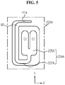
- FIG. 5 is a schematic partial plane view of the connection terminal of the busbar plate of the battery module according to another embodiment of the present disclosure.
- the busbar plate 220A may have a bent structure B2 in which a fuse portion 227A of the connection terminal 224A is bent in the horizontal direction three times.
- the fuse portion 227A may have the bent structure B2 in which the fuse portion 227A extends in the left direction (the negative direction of x coordinate) from the edge H1a of the connection opening H1, the extended end is bent forward (the negative direction of y coordinate) again, the bent end is bent to the right again, and the bent end is bent rearward (the positive direction of y coordinate) again. That is, the fuse portion 227A may be bent at 270° rotation.
- connection terminal 224A of the busbar plate 220A has the bent structure B2 that is bent three times, and thus is easy to design a longer length of the fuse portion 227A when compared to the bent structure (B1 in FIG. 4 ) in which the connection terminal 224 of the busbar plate 220 of FIG. 4 is bent once. That is, as the length of the fuse portion 227A is longer, the electrical resistance of the fuse portion 227A is higher, and thus even though the width of the fuse portion 227A is set wide, high resistance easily blows the fuse portion 227A due to the large length.
- FIG. 6 is a schematic partial plane view of the connection terminal of the busbar plate of the battery module according to another embodiment of the present disclosure.
- the busbar plate 220B may have a bent structure B3 in which a fuse portion 227B of the connection terminal 224B is bent in the horizontal direction four times.
- the fuse portion 227B may have the bent structure B3 in which the fuse portion 227B extends in the left direction (negative direction of x coordinate) from the edge H1a of the connection opening H1, the extended end is bent forward (the negative direction of y coordinate) again, the bent end is bent to the right (x axis direction) again, the bent end is bent forward (y axis direction) again, and the bent end is bent to the left (the negative direction of x coordinate) again. That is, the fuse portion 227B may be bent 360° rotation.
- connection terminal 224B of the busbar plate 220B has the bent structure B3 that is bent four times, and thus is easy to design a longer length of the fuse portion 227B compared to the bent structure in which the fuse portion 227A of the connection terminal 224 of the busbar plate 220B of FIG. 5 is bent three times. That is, as the length of the fuse portion 227B is longer, the electrical resistance of the fuse portion 227B is higher, and thus even though the width of the fuse portion 227B is set wide, high resistance easily blows the fuse portion 227B due to the large length.
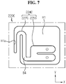
- FIG. 7 is a schematic partial plane view of the connection terminal of the busbar plate of the battery module according to another embodiment of the present disclosure.
- the busbar plate 220C may have a bent structure B4 in which a fuse portion 227C of the connection terminal 224C is bent in the horizontal direction at least three times.
- the bent structure B4 bent at least three times may be bent in the opposite directions at least twice.
- the busbar plate 220C may have the bent structure B4 in which the fuse portion 227C extends rearward (the positive direction of y coordinate) from the edge H1a of the connection opening H1, the extended end is bent forward (the negative direction of y coordinate) again, and the bent end is bent to the right (x axis direction) again. That is, the fuse portion 227C may have the bent structure B4 that is bent forward and rearward in an alternating manner at least once.
- the fuse portion 227C may have a bent portion bent in a direction and a bent portion bent in the other direction, adjacent to each other.
- the temperature of the fuse portion 227C may increase rapidly by the heat exchange between the adjacent bent portions when the high current flows. Accordingly, the fuse portion 227C of the present disclosure may blow faster.
- FIG. 8 is a schematic partial plane view of the busbar plate of the battery module according to another embodiment of the present disclosure.
- the busbar plate 220 may further include a first fixing member 230.
- the first fixing member 230 may be configured to fix the connection portion 225.
- the first fixing member 230 may include an electrically insulating material.
- the first fixing member 230 may be plastic (polyimide) having high heat resistance, or a nonconductive material, for example, stainless steel, solidified silicone or rubber.
- the first fixing member 230 may have one side connected to the inner edge H1a of the connection opening H1 and the other side connected to part of the connection portion 225.
- the busbar plate 220 further includes the electrically insulating first fixing member 230 having one side connected to the inner edge H1a of the connection opening H1 and the other side connected to part of the connection portion 225 to fix the connection portion 225, in order to reduce the vibration of the connection portion 225 when the battery module 200 continuously vibrates by an external force. Accordingly, it is possible to effectively reduce the risk that the fuse portion 227 may be cut or damaged by the continuous vibration.
- the first fixing member 230 fixes the connection portion 225 of the connection terminal 224, to prevent a short circuit from occurring between the connection portion 225 and other cylindrical battery cell 100 by the movement of the connection portion 225 due to an external force.
- FIG. 9 is a schematic partial plane view of the busbar plate of the battery module according to another embodiment of the present disclosure.
- the busbar plate 220 may further include a second fixing member 240 configured to fix the fuse portion 227.
- the second fixing member 240 may have one side connected to the edge H1a of the connection opening H1 and the other side connected to part of the fuse portion 227.
- the second fixing member 240 may include an electrically insulating material.
- the electrically insulating material may be plastic (polyimide) having high heat resistance, or a nonconductive material, for example, stainless steel, solidified silicone or rubber.
- the second fixing member 240 may have one side connected to the inner edge H1a of the connection opening H1 and the other side connected to the fuse portion 227.
- one side of the second fixing member 240 may be attached around the edge H1a.
- the other side of the second fixing member 240 may have a tube shape and may be configured to wrap around the part of the fuse portion 227.
- the second fixing member 240 may extend such that the second fixing member 240 is connected to the inner edge H1a of the connection opening H1 on one side of the tube shape that wraps around the fuse portion 227.
- the extended end of the second fixing member 240 may be configured to wrap around the part of the inner edge H1a of the connection opening H1. That is, the extended end may be in close contact with the upper surface and the lower surface of the part of the inner edge H1a of the connection opening H1. That is, the extended end may have a sandwiched structure with the edge H1a. In this instance, the extended end may be in solidified state.
- the busbar plate 220 further includes the electrically insulating second fixing member 240 having one side connected to the edge H1a of the connection opening H1 and the other side connected to part of the fuse portion 227 to fix the fuse portion 227, in order to reduce the vibration of the fuse portion 227 when the battery module 200 continuously vibrates by an external force. Accordingly, it is possible to effectively reduce the risk that the fuse portion 227 may be cut or damaged by the continuous vibration.
- At least part of the portion of the second fixing member 240 extending from the edge H1a of the connection opening H1 to part of the fuse portion 227 may have elasticity.
- the second fixing member 240 may be configured to pull the fuse portion 227 by the elastic recovery.
- at least part of the second fixing member 240 may have a spring structure (a spiral structure, S1).
- the second fixing member 240 may have one side connected to the edge H1a of the connection opening H1 and the other side connected to part of the fuse portion 227.
- the second fixing member 240 is configured to pull the fuse portion 227 by the elastic recovery when the fuse portion 227 blows, and thus when the fuse portion 227 is blown by the high current, the fuse portion 227 may be separated from the connection portion 225 with higher reliability by the elasticity of the second fixing member 240.
- FIG. 10 is a schematic partial plane view of a thermal insulation member and the connection terminal of the battery module according to another embodiment of the present disclosure.
- the busbar plate 220 may further include the thermal insulation member 250 around the outer surface of the fuse portion 227.
- the thermal insulation member 250 may include a thermally insulating material having relatively low thermal conductivity.
- the thermally insulating material may be a glass fiber or foamed plastic.
- the thermal insulation member 250 may have a tube shape that wraps around the upper surface, the horizontal side and the lower surface of the fuse portion 227.
- the busbar plate 220 further includes the thermal insulation member 250 around the outer surface of the fuse portion 227, to prevent heat from being discharged when the fuse portion 227 is melted by the high current, thereby increasing the temperature of the fuse portion 227 to blow the fuse portion 227 faster.
- thermal insulation member 250 wraps around the outer surface of the fuse portion 227, it is possible to prevent the melted part of the fuse portion 227 from moving to other internal component (e.g., the cylindrical battery cell), an electrical short circuit, or damage to other internal component.
- other internal component e.g., the cylindrical battery cell
- the thermal insulation member 250 may be separated into at least two.
- the thermal insulation member 250 separated into two may be disposed on the fuse portion 227.
- the thermal insulation member 250 as the thermal insulation member 250 is separated into at least two, the melted part of the fuse portion 227 may be induced to escape between the at least two separated portions of the thermal insulation member 250 when the fuse portion 227 is blown by the high current.
- the thermal insulation member 250 separated into at least two does not hinder the separation of the fuse portion 227 into two, thereby effectively blowing the fuse portion 227.
- FIG. 11 is a schematic bottom perspective view of a reinforcement member of the battery module according to another embodiment of the present disclosure.
- the thermal insulation member 250 of FIG. 11 may further include a discharge hole H2 to discharge the melted part of the fuse portion 227.
- the thermal insulation member 250 may include four discharge holes H2 on bottom to discharge the melted part of the fuse portion 227.
- the thermal insulation member 250 includes the discharge hole H2 to discharge the melted part of the fuse portion 227, so that the melted part of the fuse portion 227 may be induced to be discharged through the discharge hole H2 of the thermal insulation member 250 when the fuse portion 227 is blown by the high current. Accordingly, it is possible to effectively remove the melted part of the fuse portion 227, thereby effectively blowing the fuse portion 227.
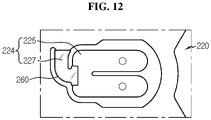
- FIG. 12 is a schematic partial plane view of the busbar plate of the battery module according to another embodiment of the present disclosure.
- the busbar plate 220 of FIG. 12 may include a reinforcement member 260 around the outer surface the fuse portion 227.
- the reinforcement member 260 may be configured to melt at a predetermined temperature or above.
- the predetermined temperature may be 300° or above.
- the reinforcement member 260 may include an electrically insulating material.
- the electrically insulating material may be Teflon ® .
- the reinforcement member 260 in melt state (in resin state) may be coated on the outer surface of the fuse portion 227 and then cured.
- the curing method may include low temperature curing and ultraviolet curing.
- the busbar plate 220 further includes the electrically insulating reinforcement member 260 configured to melt at the predetermined temperature or above around the outer surface of the fuse portion 227, to reinforce the mechanical strength of the fuse portion 227. Accordingly, when the battery module 200 of the present disclosure continuously vibrates by an external force, it is possible to effectively reduce the risk that the fuse portion 227 may be cut or damaged by the continuous vibration.
- FIG. 13 is a schematic partial side view of the busbar plate of the battery module according to another embodiment of the present disclosure. For convenience of description, only part of the fuse portion 227B of the connection terminal 224 is shown in FIG. 13 .
- At least part of the fuse portion 227B having the reinforcement member 260 may be bent in an arch shape.
- the arch shape refers to the shape of the fuse portion 227B having the central area 227b1 disposed at a higher position and two ends 227b2 disposed at a lower position. That is, when a part (in particular, the central area) of the fuse portion 227B is blown by the arch shape, the separated two parts may spread apart due to the elasticity.
- the blown part of the fuse portion 227B may be effectively separated by the elasticity of the arch shape, thereby effectively increasing the blowing reliability.
- FIG. 14 is a schematic plane view of the busbar plate of the battery module according to another embodiment of the present disclosure.
- the fuse portion 227 of the connection terminal 224 in contact with the positive electrode terminal 111 or the negative electrode terminal 112 of the cylindrical battery cell 100 disposed at the inner position in the horizontal direction may have a larger width than the fuse portion 227 of the connection terminal 224 in contact with the positive electrode terminal 111 or the negative electrode terminal 112 of the cylindrical battery cell 100 disposed at the outer position in the horizontal direction.
- the fuse portion 227 of the connection terminal 224 disposed at the inner position in the horizontal direction may have a larger vertical cross sectional area than the fuse portion 227 of the connection terminal 224 disposed at the outer position in the horizontal direction.
- the fuse portion 227 of the connection terminal 224 may have the cross section set considering the thermal balance of the plurality of cylindrical battery cells 100 horizontally arranged in rows and columns, inserted and received in the module housing 210.
- the cylindrical battery cell 100 disposed at the inner position in the horizontal direction may have higher temperature than the cylindrical battery cell 100 disposed at the outer position. Accordingly, the fuse portion 227 of the connection terminal 224 connected to the positive electrode terminal 111 or the negative electrode terminal 112 of the cylindrical battery cell 100 disposed at the inner position in the horizontal direction may have lower electrical resistance.
- one busbar plate 220 may have 6 connection terminals 224.
- the fuse portion 227 may be provided in each of 3 negative electrode connection terminals 224b connected to the negative electrode terminal 112.
- the width of the fuse portion 227D of the negative electrode connection terminal 224b disposed at the inner position in the horizontal direction may be larger than the width of the fuse portion 227 of the negative electrode connection terminal 224b disposed at the outer position in the front-rear direction.
- the fuse portion 227D of the connection terminal 224 disposed at the inner position in the horizontal direction may have a larger width than the fuse portion 227 of the connection terminal 224 disposed at the outer position in the horizontal direction.
- the fuse portion 227D of the connection terminal 224 in contact with the positive electrode terminal 111 or the negative electrode terminal 112 of the cylindrical battery cell 100 disposed at the inner position in the horizontal direction has a larger width than the fuse portion 227 of the connection terminal 224 in contact with the positive electrode terminal 111 or the negative electrode terminal 112 of the cylindrical battery cell 100 disposed at the outer position in the horizontal direction, to prevent a disconnection from occurring at or below the current value set to blow the fuse portion 227 due to high temperature at the center of the battery module 200. Accordingly, it is possible to prevent a malfunction such as a short circuit occurring when the cylindrical battery cell 100 does not abnormally operate during the use of the battery module 200.
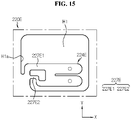
- FIG. 15 is a schematic partial plane view of the connection terminal of the busbar plate of a battery module according to another embodiment of the present disclosure.
- connection terminal 224E of the busbar plate 220E of FIG. 15 may include at least two fuse portions 227E.
- the at least two fuse portions 227E may be spaced a predetermined distance apart from each other.
- the at least two fuse portions 227E may have different horizontal widths.
- the fuse portion having a larger width is defined as a first fuse portion 227E1, and the first fuse portion 227E1 may be configured to melt and blow at the predetermined current required to protect the battery module of the present disclosure.
- the fuse portion 227E having a smaller width is defined as a second fuse portion 227E2, and the second fuse portion 227E2 may melt at a lower current than the first fuse portion 227E1.
- the electrical resistance of the first fuse portion 227E1 may be lower than that of the second fuse portion 227E2.
- the predetermined current or above may flow through the first fuse portion 227E1 having lower electrical resistance. Subsequently, when the predetermined high current or above flows in the first fuse portion 227E1 due to the abnormal behavior of the cylindrical battery cell 100 in the connection terminal 224, the first fuse portion 227E1 melts and blows, and the remaining second fuse portion 227E2 also blows by the high current. Accordingly, the fuse portion of the present disclosure may interrupt the current with higher reliability.
- connection terminal 224 includes at least two fuse portions 227E having different widths spaced the predetermined distance apart from each other, thereby increasing the durability of the connection terminal 224.
- a battery pack (not shown) may include at least one battery module 200.
- the battery pack may further include various types of devices (not shown) such as a BMS, a current sensor and a fuse to control the charge/discharge of the battery module 200.
- Ann electronic device (not shown) according to an embodiment of the present disclosure includes at least one battery module 200.
- the electronic device may further include to a device housing (not shown) having a space for receiving the battery module 200 and a display to allow the user to see the state of charge of the battery module 200.
- the battery pack according to an embodiment of the present disclosure may be included in a vehicle such as an electric vehicle or a hybrid electric vehicle. That is, the vehicle according to an embodiment of the present disclosure may include the battery pack including at least one battery module 200 according to an embodiment of the present disclosure mounted on the vehicle body itself.
- the present disclosure relates to a battery module.
- the present disclosure can be used in the industry of electronic devices comprising the battery module.
Landscapes
- Chemical & Material Sciences (AREA)
- Chemical Kinetics & Catalysis (AREA)
- Electrochemistry (AREA)
- General Chemical & Material Sciences (AREA)
- Engineering & Computer Science (AREA)
- Manufacturing & Machinery (AREA)
- Connection Of Batteries Or Terminals (AREA)
- Battery Mounting, Suspending (AREA)
- Gas Exhaust Devices For Batteries (AREA)
- Secondary Cells (AREA)
Abstract
Description
- The present disclosure relates to a battery module comprising a busbar plate, a battery pack comprising the same and an electronic device, and more particularly, to a battery module comprising a busbar plate for fast electrical disconnecting in the event of abnormal behavior (a short circuit) of a cylindrical battery cell.
- The present application claims the benefit of
Korean Patent Application No. 10-2019-0117413 filed on September 24, 2019 - Recently, there has been a dramatic increase in demand for portable electronic products such as laptop computers, video cameras and mobile phones, and with the extensive development of electric vehicles, accumulators for energy storage, robots and satellites, many studies are being made on high performance secondary batteries that can be recharged repeatedly.
- Currently, commercially available secondary batteries include nickel-cadmium batteries, nickel-hydrogen batteries, nickel-zinc batteries, lithium secondary batteries and the like, and among them, lithium secondary batteries have little or no memory effect, and thus they are gaining more attention than nickel-based batteries for their advantages that recharging can be done whenever it is convenient, the self-discharge rate is very low and the energy density is high.
- A lithium secondary battery primarily uses a lithium-based oxide and a carbon material for a positive electrode active material and a negative electrode active material respectively. Additionally, the lithium secondary battery includes an electrode assembly including a positive electrode plate and a negative electrode plate respectively coated with the positive electrode active material and the negative electrode active material and a separator interposed between the positive electrode plate and the negative electrode plate, and a packaging or a battery case in which the electrode assembly is hermetically received together with an electrolyte solution.
- The lithium secondary battery may be classified into a can-type secondary battery in which the electrode assembly is embedded in a metal can and a pouch-type secondary battery in which the electrode assembly is embedded in a pouch of an aluminum laminate sheet, according to the shape of the battery case.
- In the can-type secondary battery, the metal can in which the electrode assembly is embedded may be cylindrical. The can-type secondary battery may be used to form a battery module including a housing to receive a plurality of secondary batteries and a busbar configured to electrically connect the plurality of secondary batteries.
- Recently, in some cases, the busbar provided in the battery module uses a material having high electrical resistance to increase the resistance welding performance with the electrode terminal.
- However, when a high current flows through the busbar in some of the plurality of secondary batteries embedded in the battery module due to an electrical short circuit between the secondary batteries, a failure may occur in products using the battery module. The current may be interrupted using a battery management system (BMS), but when the BMS operates abnormally or incorrectly, there is no solution to cope with the high current, causing a failure or a fire.
- The present disclosure is designed to solve the above-described problem, and therefore the present disclosure is directed to providing a battery module comprising a busbar plate for fast electrical disconnecting in the event of abnormal behavior (a short circuit) of a cylindrical battery cell.
- These and other objects and advantages of the present disclosure can be understood by the following description, and will be apparent from the embodiments of the present disclosure. In addition, it will be readily appreciated that the objects and advantages of the present disclosure can be realized by means and combinations thereof.
- To achieve the above-described object, a battery module according to the present disclosure includes a plurality of cylindrical battery cells arranged in a horizontal direction, some cylindrical battery cells each having a positive electrode terminal and a negative electrode terminal formed on top and bottom, the remaining cylindrical battery cells each having a negative electrode terminal and a positive electrode terminal formed on top and bottom, and including a gas vent through which the positive electrode terminal or the negative electrode terminal is opened to discharge an internal gas when an internal pressure is equal to or higher than a predetermined pressure, and a busbar plate including a body portion disposed on or below the plurality of cylindrical battery cells, and having a plate shape extending in the horizontal direction to cover the plurality of cylindrical battery cells, the body portion having at least one connection opening that is open in a vertical direction in an area in contact with the positive electrode terminal or the negative electrode terminal, a positive electrode connection terminal extending from an edge of the connection opening and having the extended part in contact with the positive electrode terminal to electrically connect the plurality of cylindrical battery cells, and a negative electrode connection terminal extending from the edge of the connection opening and having the extended part in contact with the negative electrode terminal to electrically connect the plurality of cylindrical battery cells.
- Among the positive electrode connection terminal and the negative electrode connection terminal, the connection terminal in contact with the positive electrode terminal or the negative electrode terminal that is not opened by the gas vent may include a fuse portion configured to blow when a predetermined current or above flows from the cylindrical battery cell, the fuse portion having a bent structure that is bent in the horizontal direction at least once.
- Additionally, the connection terminal may further include a connection portion in direct contact with the positive electrode terminal or the negative electrode terminal of the cylindrical battery cell, and the fuse portion may extend in the horizontal direction from the inner edge of the connection opening and an end in the extended direction may be connected to one end of the connection portion.
- Additionally, the busbar plate may further include an electrically insulating first fixing member having one side connected to the inner edge of the connection opening and the other side connected to part of the connection portion to fix the connection portion.
- Additionally, the busbar plate may further include an electrically insulating second fixing member having one side connected to the edge of the connection opening and the other side connected to part of the fuse portion to fix the fuse portion.
- Additionally, at least part of a portion of the second fixing member extending from the edge of the connection opening to the part of the fuse portion may have elasticity to pull the fuse portion by elastic recovery when the fuse portion blows.
- Additionally, the busbar plate may further include a thermal insulation member around an outer surface of the fuse portion.
- Additionally, the thermal insulation element may be separated into at least two.
- Additionally, the thermal insulation element may include a discharge hole configured to discharge a melted part of the fuse portion.
- Additionally, the busbar plate may further include an electrically insulating reinforcement member around an outer surface of the fuse portion and is configured to melt at a predetermined temperature or above.
- Additionally, at least part of the fuse portion having the reinforcement member may be bent in an arch shape.
- Additionally, the battery module may further include a module housing having receiving portions with a plurality of hollows to receive the plurality of cylindrical battery cells arranged in rows and columns in the horizontal direction.
- Additionally, among the plurality of cylindrical battery cells arranged in rows and columns, the fuse portion of the connection terminal in contact with the positive electrode terminal or the negative electrode terminal of the cylindrical battery cell disposed at an inner position in the horizontal direction may have a larger width than the fuse portion of the connection terminal in contact with the positive electrode terminal or the negative electrode terminal of the cylindrical battery cell disposed at an outer position in the horizontal direction.
- Additionally, the bent structure may be bent in opposite directions at least twice.
- Additionally, the body portion may further include an external terminal electrically connected to the plurality of cylindrical battery cells at least in an area in which the connection opening is not formed.
- Additionally, the connection terminal may include at least two fuse portions, the at least two fuse portions may be spaced a predetermined distance apart from each other, and the at least two fuse portions may have different horizontal widths.
- Additionally, to achieve the above-described object, a battery pack according to the present disclosure may include at least one battery module.
- Additionally, to achieve the above-described object, an electronic device according to the present disclosure may include the battery pack.
- According to an aspect of the present disclosure, the battery module of the present disclosure includes the fuse portion in the connection terminal in contact with the positive electrode terminal or the negative electrode terminal that is not opened by the gas vent among the positive electrode connection terminal and the negative electrode connection terminal, the fuse portion configured to blow when a predetermined current or above flows from the cylindrical battery cell, to electrically isolate a specific cylindrical battery cell from the busbar plate when the high current flows in the specific cylindrical battery cell due to a short circuit between the plurality of cylindrical battery cells in the battery module. That is, it is possible to prevent a fire or thermal runaway in the battery module through the fuse portion. Accordingly, it is possible to increase the safety of the battery module.
- Additionally, as the fuse portion is provided in the connection terminal in contact with the positive electrode terminal or the negative electrode terminal that is not opened by the gas vent, the electrode terminal that is not opened by the gas vent is disposed closer to the electrode assembly than the electrode terminal that is opened by the gas vent, and thus effectively receives the internal heat of the cylindrical battery cell, and accordingly the fuse portion may blow faster and more easily by the internal heat of the cylindrical battery cell.
- Additionally, the fuse portion has the bent structure that is bent in the horizontal direction at least once, so it is easy to achieve a longer current path in the same space. That is, when the fuse portion extends linearly, it is necessary to form a larger connection opening, which places a space limitation on the electrical connection of one busbar plate with a larger number of cylindrical battery cells in a predetermined space. Accordingly, the present disclosure remarkably reduces the space occupied by the fuse portion of the busbar plate, thereby achieving the compact battery module.
- Additionally, according to an aspect of another embodiment of the present disclosure, the busbar plate further includes the electrically insulating first fixing member having one side connected to the inner edge of the connection opening and the other side connected to part of the connection portion to fix the connection portion, in order to reduce the vibration of the connection portion when the battery module continuously vibrates by an external force. Accordingly, it is possible to effectively reduce the risk that the fuse portion may be cut or damaged by the continuous vibration.
- The accompanying drawings illustrate preferred embodiments of the present disclosure and, together with the foregoing disclosure, serve to provide further understanding of the technical spirit of the present disclosure. However, the present disclosure is not to be construed as being limited to the drawings.
-
FIG. 1 is a schematic perspective view of a battery module according to an embodiment of the present disclosure. -
FIG. 2 is a schematic exploded perspective view of a battery module according to an embodiment of the present disclosure. -
FIG. 3 is a schematic cross-sectional view of a cylindrical battery cell of a battery module according to an embodiment of the present disclosure. -
FIG. 4 is a schematic plane view of a busbar plate of a battery module according to an embodiment of the present disclosure. -
FIG. 5 is a schematic partial plane view of a connection terminal of a busbar plate of a battery module according to another embodiment of the present disclosure. -
FIG. 6 is a schematic partial plane view of a connection terminal of a busbar plate of a battery module according to another embodiment of the present disclosure. -
FIG. 7 is a schematic partial plane view of a connection terminal of a busbar plate a battery module according to another embodiment of the present disclosure. -
FIG. 8 is a schematic partial plane view of a busbar plate of a battery module according to another embodiment of the present disclosure. -
FIG. 9 is a schematic partial plane view of a busbar plate of a battery module according to another embodiment of the present disclosure. -
FIG. 10 is a schematic partial plane view of a thermal insulation member and a connection terminal of a battery module according to another embodiment of the present disclosure. -
FIG. 11 is a schematic bottom perspective view of a reinforcement member of a battery module according to another embodiment of the present disclosure. -
FIG. 12 is a schematic partial plane view of a busbar plate of a battery module according to another embodiment of the present disclosure. -
FIG. 13 is a schematic partial side view of a busbar plate of a battery module according to another embodiment of the present disclosure. -
FIG. 14 is a schematic plane view of a busbar plate of a battery module according to another embodiment of the present disclosure. -
FIG. 15 is a schematic partial plane view of a connection terminal of a busbar plate of a battery module according to another embodiment of the present disclosure. - Hereinafter, the preferred embodiments of the present disclosure will be described in detail with reference to the accompanying drawings. Prior to the description, it should be understood that the terms or words used in the specification and the appended claims should not be construed as being limited to general and dictionary meanings, but rather interpreted based on the meanings and concepts corresponding to the technical aspects of the present disclosure on the basis of the principle that the inventor is allowed to define the terms appropriately for the best explanation.
- Therefore, the embodiments described herein and illustrations shown in the drawings are just a most preferred embodiment of the present disclosure, but not intended to fully describe the technical aspects of the present disclosure, so it should be understood that a variety of other equivalents and modifications could have been made thereto at the time that the application was filed.
-
FIG. 1 is a schematic perspective view of a battery module according to an embodiment of the present disclosure.FIG. 2 is a schematic exploded perspective view of the battery module according to an embodiment of the present disclosure.FIG. 3 is a schematic cross-sectional view of a cylindrical battery cell of the battery module according to an embodiment of the present disclosure. - Referring to
FIGS. 1 to 3 , thebattery module 200 according to an embodiment of the present disclosure may include a plurality ofcylindrical battery cells 100, amodule housing 210 and a plurality ofbusbar plates 220. - Here, the
cylindrical battery cell 100 may include a cylindrical battery can 116 and an electrode assembly (not shown) received in the battery can 116. - The battery can 116 may include a material having high electrical conductivity, and for example, the battery can 116 may include aluminum or copper.
- The battery can 116 may be configured to stand upright in the vertical direction. The battery can 116 may be a cylindrical shape extending in the vertical direction. The
electrode terminals positive electrode terminal 111 may be formed on the flat circular upper surface on top of the battery can 116, and thenegative electrode terminal 112 may be formed on the flat circular lower surface on bottom of the battery can 116. - The plurality of
cylindrical battery cells 100 may be arranged in rows and columns in the horizontal direction. Here, the horizontal direction refers to a direction parallel to the ground when thecylindrical battery cell 100 is placed on the ground, and may be at least one direction on the plane perpendicular to the vertical direction. The horizontal direction may be X and Y directions ofFIG. 2 . - For example, as shown in
FIG. 2 , thebattery module 200 includes 36cylindrical battery cells 100 arranged in 3 rows in the front-rear direction (y direction inFIG. 2 ) and12 columns in in the left-right direction (x direction). In this instance, among the plurality ofcylindrical battery cells 100, 18 cylindrical battery cells may have thepositive electrode terminal 111 and thenegative electrode terminal 112 disposed on top and bottom respectively, and the remaining 18 cylindrical battery cells may have thenegative electrode terminal 112 and thepositive electrode terminal 111 disposed on top and bottom respectively. - The
cylindrical battery cell 100 may include anelectrode assembly 110, a battery can 116 and acap assembly 113. - The
electrode assembly 110 may have a structure in which a positive electrode plate and a negative electrode plate with a separator interposed between are wound, and the positive electrode plate may be connected to thecap assembly 113 with apositive electrode tab 114 attached to the positive electrode plate, and the negative electrode plate may be connected to the lower end of the battery can 116 with anegative electrode tab 115 attached to the negative electrode plate. - The battery can 116 may have an empty internal space to receive the
electrode assembly 110. In particular, the battery can 116 may have a cylindrical or prismatic shape with an open top. The battery can 116 may be made of a metal such as steel or aluminum to ensure stiffness. The battery can 116 may have the negative electrode tab attached to the lower end, and not only the lower part of the battery can 116 but also the battery can 116 itself may act as thenegative electrode terminal 112. - The
cap assembly 113 may be coupled to the top opening of the battery can 116 to hermetically close the open end of the battery can 116. Thecap assembly 113 may have a circular or prismatic shape according to the shape of the battery can 116, and may include subcomponents such as a top cap C1, a gas vent C2 and a gasket C3. - Here, the top cap C1 may be disposed on the outermost side of the
cap assembly 113, and extend in the upward direction. In particular, the top cap C1 may act as thepositive electrode terminal 111 of thecylindrical battery cell 100. Accordingly, the top cap C1 may be electrically connected to othercylindrical battery cell 100, a load or a charger through an external device, for example, thebusbar plate 220. The top cap C1 may be made of a metal such as, for example, stainless steel or aluminum. - The gas vent C2 may be configured to change the shape when the internal pressure of the
cylindrical battery cell 100, i.e., the internal gas pressure of the battery can 116 is equal to or higher than a predetermined pressure. For example, when the internal gas of the battery can 116 may be discharged through the gas vent C2, the top cap C1 may be opened. That is, thepositive electrode terminal 111 or thenegative electrode terminal 112 may be opened through the gas vent C2. For example, the gas vent C2 may be configured to break in part by the internal gas pressure of the battery can 116. Through the broken portion of the gas vent C2, the internal gas may be discharged. In this instance, the gas may be discharged through a hole formed in the peripheral area of thepositive electrode terminal 111. - The gasket C3 may be made of an electrically insulating material to insulate the circumferential area of the top cap C1 and the gas vent C2 from the battery can 116.
- The
cap assembly 113 may further include a current interrupt element C4. The current interrupt element C4 may be referred to as a Current Interrupt Device (CID), and when the shape of the gas vent C2 is changed by the increased internal pressure of the battery due to the gas generation, the contact between the gas vent C2 and the current interrupt element C4 is separated or the current interrupt element C4 is broken, causing disconnection of the electrical connection between the gas vent C2 and theelectrode assembly 110. - The configuration of the
cylindrical battery cell 100 is well known to those skilled in the art at the time of filing the patent application, and its detailed description is omitted herein. AlthoughFIG. 3 shows an example of thecylindrical battery cell 100, thebattery module 200 according to the present disclosure is not limited to a specific type ofcylindrical battery cell 100. That is, various types of secondary batteries known at the time of filing the patent application may be used in thebattery module 200 according to the present disclosure. - The
module housing 210 may include anupper case 211 and alower case 212. - The
upper case 211 and thelower case 212 may have receivingportions cylindrical battery cell 100 is inserted and received respectively. In detail, each of the receivingportions cylindrical battery cell 100. - The
module housing 210 may include an electrically insulating plastic. The plastic may be, for example, polyvinyl chloride, nylon or polyethylene terephthalate. - Here, the terms representing the directions such as front, rear, left, right, up, and down may vary depending on the position of the observer or the placement of the object. However, in the specification, for convenience of description, the directions such as front, rear, left, right, up, and down are defined when viewed from the direction F.
-
FIG. 4 is a schematic plane view of the busbar plate of the battery module according to an embodiment of the present disclosure. - Referring to
FIG. 4 together withFIG. 2 , thebusbar plate 220 may be, on one surface, electrically connected in contact with theelectrode terminals cylindrical battery cells 100. That is, thebusbar plate 220 may be configured to come into contact with thepositive electrode terminal 111 or thenegative electrode terminal 112 of the plurality ofcylindrical battery cells 100 to electrically connect the plurality ofcylindrical battery cells 100. - In detail, the
busbar plate 220 may include abody portion 221 and aconnection terminal 224. In this instance, theconnection terminal 224 may include a positiveelectrode connection terminal 224a configured to be connected to apositive electrode terminal 111 and a negativeelectrode connection terminal 224b configured to be connected to anegative electrode terminal 112. - Here, the
body portion 221 may have a plate shape that is flat in the horizontal direction to cover the plurality ofcylindrical battery cells 100. In other words, thebody portion 221 may have a plate shape having the upper and lower surfaces that are wider than the horizontal sides (x direction, y direction). Thebody portion 221 may be disposed on top or bottom of the plurality ofcylindrical battery cells 100 where thepositive electrode terminal 111 or thenegative electrode terminal 112 is formed. Thebody portion 221 and theconnection terminal 224 may include an electrically conductive metal to electrically connect the plurality ofcylindrical battery cells 100. The electrically conductive metal may be an alloy of nickel, copper, aluminum. - An
external terminal 228 electrically connected to the plurality ofcylindrical battery cells 100 may be provided at least in an area of thebody portion 221 in which the connection opening H1 is not formed. Theexternal terminal 228 may be configured to be electrically connected to a battery management system (not shown). Alternatively, theexternal terminal 228 may be electrically connected toother busbar plate 220 of thebattery module 200. - The
body portion 221 may have at least one connection opening H1 that is open in the vertical direction. The connection opening H1 may be open in the vertical direction at an area facing thepositive electrode terminal 111 or thenegative electrode terminal 112. - The positive
electrode connection terminal 224a may extend from an edge H1a of the connection opening H1, and the extended portion may come into contact with thepositive electrode terminal 111 to electrically connect the plurality ofcylindrical battery cells 100. - The negative
electrode connection terminal 224b may extend from the edge H1a of the connection opening H1, and the extended portion may come into contact with thenegative electrode terminal 112 to electrically connect the plurality ofcylindrical battery cells 100. - For example, as shown in
FIG. 4 , onebusbar plate 220 of the present disclosure may include thebody portion 221 of a plate shape that is flat in the horizontal direction, 3 positiveelectrode connection terminals electrode connection terminals 224b. - The positive
electrode connection terminal 224a and the negativeelectrode connection terminal 224b may extend in the horizontal direction from the edge H1a of the connection opening H1. That is, the positiveelectrode connection terminal 224a and the negativeelectrode connection terminal 224b may be disposed in the connection opening H1. - Among the positive
electrode connection terminal 224a and the negativeelectrode connection terminal 224b, theconnection terminal 224b in contact with thepositive electrode terminal 111 or thenegative electrode terminal 112 that is no opened by the gas vent C2 may include afuse portion 227. Thefuse portion 227 may be configured to blow when a predetermined current or above flows from thecylindrical battery cell 100. That is, when the predetermined current or above flows, part of thefuse portion 227 may be melted and lost by the resistance heat. By this principle, thefuse portion 227 may be electrically disconnected. - The
fuse portion 227 may have a bent structure B1 bent in the horizontal direction at least once. For example, as shown inFIG. 4 , thefuse portion 227 may have the bent structure B1 in which thefuse portion 227 extends in the front-rear direction (y direction) from the edge H1a of the connection opening H1, and the extended end is bent again in the right direction (x direction). - According to this configuration of the present disclosure, among the positive
electrode connection terminal 224a and the negativeelectrode connection terminal 224b, theconnection terminal 224 in contact with thepositive electrode terminal 111 or thenegative electrode terminal 112 that is not opened by the gas vent C2 includes thefuse portion 227 configured to blow when the predetermined current or above flows from thecylindrical battery cell 100, causing a short circuit between the plurality ofcylindrical battery cells 100 in thebattery module 200, so that the specificcylindrical battery cell 100 may be electrically isolated from thebusbar plate 220 by thefuse portion 227 when the high current flows in the specificcylindrical battery cell 100. That is, it is possible to prevent a fire or thermal runaway in thebattery module 200 through thefuse portion 227. Accordingly, it is possible to increase the safety of thebattery module 200. - As the
fuse portion 227 is provided in theconnection terminal 224 in contact with thepositive electrode terminal 111 or thenegative electrode terminal 112 that is not opened by the gas vent C2, the electrode terminal (e.g., the negative electrode terminal) that is not opened by the gas vent C2 is disposed closer to the electrode assembly than the electrode terminal that is opened by the gas vent C2, and thus effectively receives the internal heat of thecylindrical battery cell 100, thereby causing the internal heat of thecylindrical battery cell 100 to blow thefuse portion 227 faster and more easily. - The
fuse portion 227 has the bent structure B1 that is bent in the horizontal direction at least once, so it is easier to achieve a longer current path in the same space. That is, when thefuse portion 227 extends linearly, it is necessary to form a larger connection opening H1, which places a space limitation on the electrical connection of onebusbar plate 220 with a larger number ofcylindrical battery cells 100 in a predetermined space. Accordingly, the present disclosure remarkably reduces the space occupied by thefuse portion 227 of thebusbar plate 220, thereby achieving thecompact battery module 200. - Referring back to
FIG. 4 , in more detail, each of the positiveelectrode connection terminal 224a and the negativeelectrode connection terminal 224b may further include aconnection portion 225 in direct contact with or welded to thepositive electrode terminal 111 and thenegative electrode terminal 112 of thecylindrical battery cell 100 respectively. - The
connection portion 225 may have a branched structure branched into two in the horizontal direction. The branched structure may help the resistance welding of thepositive electrode terminal 111 or thenegative electrode terminal 112 and theconnection portion 225. A welding point is provided in each of the two branches of the branched structure, and a welding rod (not shown) comes into contact with the welding point. - The
fuse portion 227 may have a structure in which thefuse portion 227 extends in the horizontal direction from the inner edge H1a of the connection opening H1 and the end of the extended direction is connected to one end of theconnection portion 225. -
FIG. 5 is a schematic partial plane view of the connection terminal of the busbar plate of the battery module according to another embodiment of the present disclosure. - Referring to
FIG. 5 , thebusbar plate 220A according to another embodiment of the present disclosure may have a bent structure B2 in which afuse portion 227A of theconnection terminal 224A is bent in the horizontal direction three times. For example, as shown inFIG. 5 , thefuse portion 227A may have the bent structure B2 in which thefuse portion 227A extends in the left direction (the negative direction of x coordinate) from the edge H1a of the connection opening H1, the extended end is bent forward (the negative direction of y coordinate) again, the bent end is bent to the right again, and the bent end is bent rearward (the positive direction of y coordinate) again. That is, thefuse portion 227A may be bent at 270° rotation. - Accordingly, the
connection terminal 224A of thebusbar plate 220A according to another embodiment of the present disclosure has the bent structure B2 that is bent three times, and thus is easy to design a longer length of thefuse portion 227A when compared to the bent structure (B1 inFIG. 4 ) in which theconnection terminal 224 of thebusbar plate 220 ofFIG. 4 is bent once. That is, as the length of thefuse portion 227A is longer, the electrical resistance of thefuse portion 227A is higher, and thus even though the width of thefuse portion 227A is set wide, high resistance easily blows thefuse portion 227A due to the large length. -
FIG. 6 is a schematic partial plane view of the connection terminal of the busbar plate of the battery module according to another embodiment of the present disclosure. - Referring to
FIG. 6 , thebusbar plate 220B according to another embodiment of the present disclosure may have a bent structure B3 in which afuse portion 227B of theconnection terminal 224B is bent in the horizontal direction four times. For example, as shown inFIG. 6 , thefuse portion 227B may have the bent structure B3 in which thefuse portion 227B extends in the left direction (negative direction of x coordinate) from the edge H1a of the connection opening H1, the extended end is bent forward (the negative direction of y coordinate) again, the bent end is bent to the right (x axis direction) again, the bent end is bent forward (y axis direction) again, and the bent end is bent to the left (the negative direction of x coordinate) again. That is, thefuse portion 227B may be bent 360° rotation. - Accordingly, the
connection terminal 224B of thebusbar plate 220B according to another embodiment of the present disclosure has the bent structure B3 that is bent four times, and thus is easy to design a longer length of thefuse portion 227B compared to the bent structure in which thefuse portion 227A of theconnection terminal 224 of thebusbar plate 220B ofFIG. 5 is bent three times. That is, as the length of thefuse portion 227B is longer, the electrical resistance of thefuse portion 227B is higher, and thus even though the width of thefuse portion 227B is set wide, high resistance easily blows thefuse portion 227B due to the large length. -
FIG. 7 is a schematic partial plane view of the connection terminal of the busbar plate of the battery module according to another embodiment of the present disclosure. - Referring to
FIG. 7 , thebusbar plate 220C according to another embodiment of the present disclosure may have a bent structure B4 in which afuse portion 227C of theconnection terminal 224C is bent in the horizontal direction at least three times. In this instance, the bent structure B4 bent at least three times may be bent in the opposite directions at least twice. - For example, as shown in
FIG. 7 , thebusbar plate 220C according to another embodiment of the present disclosure may have the bent structure B4 in which thefuse portion 227C extends rearward (the positive direction of y coordinate) from the edge H1a of the connection opening H1, the extended end is bent forward (the negative direction of y coordinate) again, and the bent end is bent to the right (x axis direction) again. That is, thefuse portion 227C may have the bent structure B4 that is bent forward and rearward in an alternating manner at least once. - According to this configuration of the present disclosure, as the bent structure B4 of the
fuse portion 227C of theconnection terminal 224C is bent in the opposite directions at least twice, thefuse portion 227C may have a bent portion bent in a direction and a bent portion bent in the other direction, adjacent to each other. In this structure, the temperature of thefuse portion 227C may increase rapidly by the heat exchange between the adjacent bent portions when the high current flows. Accordingly, thefuse portion 227C of the present disclosure may blow faster. -
FIG. 8 is a schematic partial plane view of the busbar plate of the battery module according to another embodiment of the present disclosure. - Referring to
FIG. 8 , thebusbar plate 220 may further include a first fixingmember 230. - In detail, the first fixing
member 230 may be configured to fix theconnection portion 225. Thefirst fixing member 230 may include an electrically insulating material. For example, the first fixingmember 230 may be plastic (polyimide) having high heat resistance, or a nonconductive material, for example, stainless steel, solidified silicone or rubber. Thefirst fixing member 230 may have one side connected to the inner edge H1a of the connection opening H1 and the other side connected to part of theconnection portion 225. - According to this configuration of the present disclosure, the
busbar plate 220 further includes the electrically insulating first fixingmember 230 having one side connected to the inner edge H1a of the connection opening H1 and the other side connected to part of theconnection portion 225 to fix theconnection portion 225, in order to reduce the vibration of theconnection portion 225 when thebattery module 200 continuously vibrates by an external force. Accordingly, it is possible to effectively reduce the risk that thefuse portion 227 may be cut or damaged by the continuous vibration. - When the
fuse portion 227 is blown by the high current, the first fixingmember 230 fixes theconnection portion 225 of theconnection terminal 224, to prevent a short circuit from occurring between theconnection portion 225 and othercylindrical battery cell 100 by the movement of theconnection portion 225 due to an external force. -
FIG. 9 is a schematic partial plane view of the busbar plate of the battery module according to another embodiment of the present disclosure. - Referring to
FIG. 9 , thebusbar plate 220 may further include a second fixing member 240 configured to fix thefuse portion 227. The second fixing member 240 may have one side connected to the edge H1a of the connection opening H1 and the other side connected to part of thefuse portion 227. The second fixing member 240 may include an electrically insulating material. For example, the electrically insulating material may be plastic (polyimide) having high heat resistance, or a nonconductive material, for example, stainless steel, solidified silicone or rubber. - The second fixing member 240 may have one side connected to the inner edge H1a of the connection opening H1 and the other side connected to the
fuse portion 227. In more detail, one side of the second fixing member 240 may be attached around the edge H1a. The other side of the second fixing member 240 may have a tube shape and may be configured to wrap around the part of thefuse portion 227. The second fixing member 240 may extend such that the second fixing member 240 is connected to the inner edge H1a of the connection opening H1 on one side of the tube shape that wraps around thefuse portion 227. - The extended end of the second fixing member 240 may be configured to wrap around the part of the inner edge H1a of the connection opening H1. That is, the extended end may be in close contact with the upper surface and the lower surface of the part of the inner edge H1a of the connection opening H1. That is, the extended end may have a sandwiched structure with the edge H1a. In this instance, the extended end may be in solidified state.
- According to this configuration of the present disclosure, the
busbar plate 220 further includes the electrically insulating second fixing member 240 having one side connected to the edge H1a of the connection opening H1 and the other side connected to part of thefuse portion 227 to fix thefuse portion 227, in order to reduce the vibration of thefuse portion 227 when thebattery module 200 continuously vibrates by an external force. Accordingly, it is possible to effectively reduce the risk that thefuse portion 227 may be cut or damaged by the continuous vibration. - Referring back to
FIG. 9 , at least part of the portion of the second fixing member 240 extending from the edge H1a of the connection opening H1 to part of thefuse portion 227 may have elasticity. When thefuse portion 227 blows, the second fixing member 240 may be configured to pull thefuse portion 227 by the elastic recovery. For example, at least part of the second fixing member 240 may have a spring structure (a spiral structure, S1). The second fixing member 240 may have one side connected to the edge H1a of the connection opening H1 and the other side connected to part of thefuse portion 227. - According to this configuration of the present disclosure, as at least part of the portion of the second fixing member 240 extending from the edge H1a of the connection opening H1 to the part of the
fuse portion 227 has elasticity, the second fixing member 240 is configured to pull thefuse portion 227 by the elastic recovery when thefuse portion 227 blows, and thus when thefuse portion 227 is blown by the high current, thefuse portion 227 may be separated from theconnection portion 225 with higher reliability by the elasticity of the second fixing member 240. -
FIG. 10 is a schematic partial plane view of a thermal insulation member and the connection terminal of the battery module according to another embodiment of the present disclosure. - Referring to
FIG. 10 , thebusbar plate 220 may further include thethermal insulation member 250 around the outer surface of thefuse portion 227. Thethermal insulation member 250 may include a thermally insulating material having relatively low thermal conductivity. The thermally insulating material may be a glass fiber or foamed plastic. For example, thethermal insulation member 250 may have a tube shape that wraps around the upper surface, the horizontal side and the lower surface of thefuse portion 227. - According to this configuration of the present disclosure, the
busbar plate 220 further includes thethermal insulation member 250 around the outer surface of thefuse portion 227, to prevent heat from being discharged when thefuse portion 227 is melted by the high current, thereby increasing the temperature of thefuse portion 227 to blow thefuse portion 227 faster. - As the
thermal insulation member 250 wraps around the outer surface of thefuse portion 227, it is possible to prevent the melted part of thefuse portion 227 from moving to other internal component (e.g., the cylindrical battery cell), an electrical short circuit, or damage to other internal component. - Referring back to
FIG. 10 , thethermal insulation member 250 may be separated into at least two. For example, as shown inFIG. 10 , thethermal insulation member 250 separated into two may be disposed on thefuse portion 227. - According to this configuration of the present disclosure, as the
thermal insulation member 250 is separated into at least two, the melted part of thefuse portion 227 may be induced to escape between the at least two separated portions of thethermal insulation member 250 when thefuse portion 227 is blown by the high current. Thethermal insulation member 250 separated into at least two does not hinder the separation of thefuse portion 227 into two, thereby effectively blowing thefuse portion 227. -
FIG. 11 is a schematic bottom perspective view of a reinforcement member of the battery module according to another embodiment of the present disclosure. - Referring to
FIG. 11 together withFIG. 10 , thethermal insulation member 250 ofFIG. 11 may further include a discharge hole H2 to discharge the melted part of thefuse portion 227. For example, as shown inFIG. 11 , thethermal insulation member 250 may include four discharge holes H2 on bottom to discharge the melted part of thefuse portion 227. - According to this configuration of the present disclosure, the
thermal insulation member 250 includes the discharge hole H2 to discharge the melted part of thefuse portion 227, so that the melted part of thefuse portion 227 may be induced to be discharged through the discharge hole H2 of thethermal insulation member 250 when thefuse portion 227 is blown by the high current. Accordingly, it is possible to effectively remove the melted part of thefuse portion 227, thereby effectively blowing thefuse portion 227. -
FIG. 12 is a schematic partial plane view of the busbar plate of the battery module according to another embodiment of the present disclosure. - Referring to
FIG. 12 , thebusbar plate 220 ofFIG. 12 may include areinforcement member 260 around the outer surface thefuse portion 227. Thereinforcement member 260 may be configured to melt at a predetermined temperature or above. For example, the predetermined temperature may be 300° or above. Thereinforcement member 260 may include an electrically insulating material. For example, the electrically insulating material may be Teflon®. Thereinforcement member 260 in melt state (in resin state) may be coated on the outer surface of thefuse portion 227 and then cured. The curing method may include low temperature curing and ultraviolet curing. - According to this configuration of the present disclosure, the
busbar plate 220 further includes the electrically insulatingreinforcement member 260 configured to melt at the predetermined temperature or above around the outer surface of thefuse portion 227, to reinforce the mechanical strength of thefuse portion 227. Accordingly, when thebattery module 200 of the present disclosure continuously vibrates by an external force, it is possible to effectively reduce the risk that thefuse portion 227 may be cut or damaged by the continuous vibration. -
FIG. 13 is a schematic partial side view of the busbar plate of the battery module according to another embodiment of the present disclosure. For convenience of description, only part of thefuse portion 227B of theconnection terminal 224 is shown inFIG. 13 . - At least part of the
fuse portion 227B having thereinforcement member 260 may be bent in an arch shape. Here, the arch shape refers to the shape of thefuse portion 227B having the central area 227b1 disposed at a higher position and two ends 227b2 disposed at a lower position. That is, when a part (in particular, the central area) of thefuse portion 227B is blown by the arch shape, the separated two parts may spread apart due to the elasticity. - According to this configuration of the present disclosure, as at least part of the
fuse portion 227B having thereinforcement member 260 is bent in an arch shape, the blown part of thefuse portion 227B may be effectively separated by the elasticity of the arch shape, thereby effectively increasing the blowing reliability. -
FIG. 14 is a schematic plane view of the busbar plate of the battery module according to another embodiment of the present disclosure. - Referring to
FIG. 14 together withFIG. 2 , among the plurality ofcylindrical battery cells 100 arranged in rows and columns, thefuse portion 227 of theconnection terminal 224 in contact with thepositive electrode terminal 111 or thenegative electrode terminal 112 of thecylindrical battery cell 100 disposed at the inner position in the horizontal direction may have a larger width than thefuse portion 227 of theconnection terminal 224 in contact with thepositive electrode terminal 111 or thenegative electrode terminal 112 of thecylindrical battery cell 100 disposed at the outer position in the horizontal direction. - That is, the
fuse portion 227 of theconnection terminal 224 disposed at the inner position in the horizontal direction may have a larger vertical cross sectional area than thefuse portion 227 of theconnection terminal 224 disposed at the outer position in the horizontal direction. - The
fuse portion 227 of theconnection terminal 224 may have the cross section set considering the thermal balance of the plurality ofcylindrical battery cells 100 horizontally arranged in rows and columns, inserted and received in themodule housing 210. - In other words, during charging and discharging of the
battery module 200, among the plurality ofcylindrical battery cells 100, thecylindrical battery cell 100 disposed at the inner position in the horizontal direction may have higher temperature than thecylindrical battery cell 100 disposed at the outer position. Accordingly, thefuse portion 227 of theconnection terminal 224 connected to thepositive electrode terminal 111 or thenegative electrode terminal 112 of thecylindrical battery cell 100 disposed at the inner position in the horizontal direction may have lower electrical resistance. - For example, as shown in
FIG. 14 , onebusbar plate 220 may have 6connection terminals 224. Among the 6connection terminals 224, thefuse portion 227 may be provided in each of 3 negativeelectrode connection terminals 224b connected to thenegative electrode terminal 112. In this instance, among the 3 negativeelectrode connection terminals 224b, the width of thefuse portion 227D of the negativeelectrode connection terminal 224b disposed at the inner position in the horizontal direction may be larger than the width of thefuse portion 227 of the negativeelectrode connection terminal 224b disposed at the outer position in the front-rear direction. - That is, the
fuse portion 227D of theconnection terminal 224 disposed at the inner position in the horizontal direction may have a larger width than thefuse portion 227 of theconnection terminal 224 disposed at the outer position in the horizontal direction. - According to this configuration of the present disclosure, among the plurality of
cylindrical battery cells 100 arranged in rows and columns, thefuse portion 227D of theconnection terminal 224 in contact with thepositive electrode terminal 111 or thenegative electrode terminal 112 of thecylindrical battery cell 100 disposed at the inner position in the horizontal direction has a larger width than thefuse portion 227 of theconnection terminal 224 in contact with thepositive electrode terminal 111 or thenegative electrode terminal 112 of thecylindrical battery cell 100 disposed at the outer position in the horizontal direction, to prevent a disconnection from occurring at or below the current value set to blow thefuse portion 227 due to high temperature at the center of thebattery module 200. Accordingly, it is possible to prevent a malfunction such as a short circuit occurring when thecylindrical battery cell 100 does not abnormally operate during the use of thebattery module 200. -
FIG. 15 is a schematic partial plane view of the connection terminal of the busbar plate of a battery module according to another embodiment of the present disclosure. - Referring to
FIG. 15 , as opposed to theconnection terminal 224 ofFIG. 4 , theconnection terminal 224E of thebusbar plate 220E ofFIG. 15 may include at least twofuse portions 227E. In this instance, the at least twofuse portions 227E may be spaced a predetermined distance apart from each other. In this instance, the at least twofuse portions 227E may have different horizontal widths. - For example, among the at least two
fuse portions 227E, the fuse portion having a larger width is defined as a first fuse portion 227E1, and the first fuse portion 227E1 may be configured to melt and blow at the predetermined current required to protect the battery module of the present disclosure. Thefuse portion 227E having a smaller width is defined as a second fuse portion 227E2, and the second fuse portion 227E2 may melt at a lower current than the first fuse portion 227E1. The electrical resistance of the first fuse portion 227E1 may be lower than that of the second fuse portion 227E2. - That is, for example, while the battery module normally operates, the predetermined current or above may flow through the first fuse portion 227E1 having lower electrical resistance. Subsequently, when the predetermined high current or above flows in the first fuse portion 227E1 due to the abnormal behavior of the
cylindrical battery cell 100 in theconnection terminal 224, the first fuse portion 227E1 melts and blows, and the remaining second fuse portion 227E2 also blows by the high current. Accordingly, the fuse portion of the present disclosure may interrupt the current with higher reliability. - According to this configuration of the present disclosure, compared to the
fuse portion 227 ofFIG. 4 including only onefuse portion 227, theconnection terminal 224 includes at least twofuse portions 227E having different widths spaced the predetermined distance apart from each other, thereby increasing the durability of theconnection terminal 224. - A battery pack (not shown) according to an embodiment of the present disclosure may include at least one
battery module 200. The battery pack may further include various types of devices (not shown) such as a BMS, a current sensor and a fuse to control the charge/discharge of thebattery module 200. - Ann electronic device (not shown) according to an embodiment of the present disclosure includes at least one
battery module 200. The electronic device may further include to a device housing (not shown) having a space for receiving thebattery module 200 and a display to allow the user to see the state of charge of thebattery module 200. - The battery pack according to an embodiment of the present disclosure may be included in a vehicle such as an electric vehicle or a hybrid electric vehicle. That is, the vehicle according to an embodiment of the present disclosure may include the battery pack including at least one
battery module 200 according to an embodiment of the present disclosure mounted on the vehicle body itself. - The terms indicating directions as used herein such as upper, lower, left, right, front and rear are used for convenience of description only, and it is obvious to those skilled in the art that the term may change depending on the position of the stated element or an observer.
- While the present disclosure has been hereinabove described with regard to a limited number of embodiments and drawings, the present disclosure is not limited thereto and it is obvious to those skilled in the art that various modifications and changes may be made thereto within the technical aspects of the present disclosure and the equivalent scope of the appended claims.
[Description of Reference Numerals] 200: Battery module 220: Busbar plate 221: Body portion 224, 224a, 224b: Connection terminal, Positive electrode connection terminal, Negative electrode connection terminal 100: Cylindrical battery cell C2: Gas vent 111, 112: Positive electrode terminal, Negative electrode terminal B1: Bent structure 210: Module housing P1: Connection opening 225: Connection portion 227: Fuse portion 230: First fixing member 240: Second fixing member 250: Thermal insulation member H2: Discharge hole 260: Reinforcement member - The present disclosure relates to a battery module. In addition, the present disclosure can be used in the industry of electronic devices comprising the battery module.
Claims (16)
- A battery module, comprising:a plurality of cylindrical battery cells arranged in a horizontal direction, some cylindrical battery cells each having a positive electrode terminal and a negative electrode terminal formed on top and bottom, the remaining cylindrical battery cells each having a negative electrode terminal and a positive electrode terminal formed on top and bottom, and including a gas vent through which the positive electrode terminal or the negative electrode terminal is opened to discharge an internal gas when an internal pressure is equal to or higher than a predetermined pressure; anda busbar plate including a body portion disposed on or below the plurality of cylindrical battery cells, and having a plate shape extending in the horizontal direction to cover the plurality of cylindrical battery cells, the body portion having at least one connection opening that is open in a vertical direction in an area in contact with the positive electrode terminal or the negative electrode terminal, a positive electrode connection terminal extending from an edge of the connection opening and having the extended part in contact with the positive electrode terminal to electrically connect the plurality of cylindrical battery cells, and a negative electrode connection terminal extending from the edge of the connection opening and having the extended part in contact with the negative electrode terminal to electrically connect the plurality of cylindrical battery cells,wherein among the positive electrode connection terminal and the negative electrode connection terminal, the connection terminal in contact with the positive electrode terminal or the negative electrode terminal that is not opened by the gas vent includes a fuse portion configured to blow when a predetermined current or above flows from the cylindrical battery cell, the fuse portion having a bent structure that is bent in the horizontal direction at least once.
- The battery module according to claim 1, wherein the connection terminal further includes a connection portion in direct contact with the positive electrode terminal or the negative electrode terminal of the cylindrical battery cell, and
the fuse portion extends in the horizontal direction from the inner edge of the connection opening and an end in the extended direction is connected to one end of the connection portion. - The battery module according to claim 2, wherein the busbar plate further includes an electrically insulating first fixing member having one side connected to the inner edge of the connection opening and the other side connected to part of the connection portion to fix the connection portion.
- The battery module according to claim 2, wherein the busbar plate further includes an electrically insulating second fixing member having one side connected to the edge of the connection opening and the other side connected to part of the fuse portion to fix the fuse portion.
- The battery module according to claim 4, wherein at least part of a portion of the second fixing member extending from the edge of the connection opening to the part of the fuse portion has elasticity to pull the fuse portion by elastic recovery when the fuse portion blows.
- The battery module according to claim 2, wherein the busbar plate further includes a thermal insulation member around an outer surface of the fuse portion.
- The battery module according to claim 6, wherein the thermal insulation member is separated into at least two.
- The battery module according to claim 6, wherein the thermal insulation member includes a discharge hole configured to discharge a melted part of the fuse portion.
- The battery module according to claim 2, wherein the busbar plate further includes an electrically insulating reinforcement member around an outer surface of the fuse portion and is configured to melt at a predetermined temperature or above.
- The battery module according to claim 9, wherein at least part of the fuse portion having the reinforcement member is bent in an arch shape.
- The battery module according to claim 9, wherein the battery module further includes a module housing having receiving portions with a plurality of hollows to receive the plurality of cylindrical battery cells arranged in rows and columns in the horizontal direction, and
among the plurality of cylindrical battery cells arranged in rows and columns, the fuse portion of the connection terminal in contact with the positive electrode terminal or the negative electrode terminal of the cylindrical battery cell disposed at an inner position in the horizontal direction has a larger width than the fuse portion of the connection terminal in contact with the positive electrode terminal or the negative electrode terminal of the cylindrical battery cell disposed at an outer position in the horizontal direction. - The battery module according to claim 1, wherein the bent structure is bent in opposite directions at least twice.
- The battery module according to claim 1, wherein the body portion further includes an external terminal electrically connected to the plurality of cylindrical battery cells at least in an area in which the connection opening is not formed.
- The battery module according to claim 1, wherein the connection terminal includes at least two fuse portions, and the at least two fuse portions are spaced a predetermined distance apart from each other, and
the at least two fuse portions have different horizontal widths. - A battery pack comprising at least one battery module according to any one of claims 1 to 14.
- An electronic device comprising the battery pack according to claim 15.
Applications Claiming Priority (2)
| Application Number | Priority Date | Filing Date | Title |
|---|---|---|---|
| KR1020190117413A KR102820678B1 (en) | 2019-09-24 | 2019-09-24 | Battery Module Comprising Busbar Plate and Battery Pack Having the Same and Electric Device |
| PCT/KR2020/010811 WO2021060704A1 (en) | 2019-09-24 | 2020-08-13 | Battery module comprising bus bar plate, battery pack comprising same, and electronic device |
Publications (2)
| Publication Number | Publication Date |
|---|---|
| EP3989353A1 true EP3989353A1 (en) | 2022-04-27 |
| EP3989353A4 EP3989353A4 (en) | 2022-08-10 |
Family
ID=75166768
Family Applications (1)
| Application Number | Title | Priority Date | Filing Date |
|---|---|---|---|
| EP20869106.3A Pending EP3989353A4 (en) | 2019-09-24 | 2020-08-13 | BATTERY MODULE COMPRISING A BUSBAR PLATE, BATTERY PACK COMPRISING THE SAME, AND ELECTRONIC DEVICE |
Country Status (6)
| Country | Link |
|---|---|
| US (1) | US12206131B2 (en) |
| EP (1) | EP3989353A4 (en) |
| JP (1) | JP7372348B2 (en) |
| KR (1) | KR102820678B1 (en) |
| CN (1) | CN113939953B (en) |
| WO (1) | WO2021060704A1 (en) |
Cited By (3)
| Publication number | Priority date | Publication date | Assignee | Title |
|---|---|---|---|---|
| US20220416378A1 (en) * | 2021-06-28 | 2022-12-29 | Makita Corporation | Battery pack |
| EP4550561A4 (en) * | 2022-06-30 | 2025-10-22 | Panasonic Energy Co Ltd | BATTERY PACK |
| WO2026068817A1 (en) * | 2024-09-27 | 2026-04-02 | Elringklinger Ag | Cell contacting system, and battery module and/or pack |
Families Citing this family (12)
| Publication number | Priority date | Publication date | Assignee | Title |
|---|---|---|---|---|
| EP4645574A4 (en) * | 2022-12-27 | 2026-05-06 | Panasonic Ip Man Co Ltd | POWER STORAGE MODULE |
| CN219873943U (en) * | 2023-04-20 | 2023-10-20 | 惠州亿纬锂能股份有限公司 | Output pole composite structure, CCS assembly and battery module |
| FR3149435B1 (en) * | 2023-05-31 | 2025-06-27 | Renault Sas | System for removably fixing and electrically connecting an energy storage element. |
| DE102023114656A1 (en) * | 2023-06-05 | 2024-12-05 | Bayerische Motoren Werke Aktiengesellschaft | Electrical energy storage device for a motor vehicle, in particular for a motor vehicle, and motor vehicle |
| DE102023205391A1 (en) * | 2023-06-09 | 2024-12-12 | Robert Bosch Gesellschaft mit beschränkter Haftung | battery pack |
| EP4507089A3 (en) * | 2023-08-11 | 2025-06-18 | Schneider Electric IT Corporation | Methods and systems for decoupling batteries in the event of a thermal runaway |
| WO2025077342A1 (en) * | 2023-10-11 | 2025-04-17 | 湖北亿纬动力有限公司 | Busbar assembly, battery module and battery pack |
| WO2025115862A1 (en) * | 2023-11-30 | 2025-06-05 | パナソニックIpマネジメント株式会社 | Electric power storage module |
| WO2025114885A1 (en) * | 2023-12-01 | 2025-06-05 | SES (Shanghai) Co., Ltd. | System and method for arranging battery cells based on groupings of prime numbers of cells connected in parallel |
| WO2025205279A1 (en) * | 2024-03-29 | 2025-10-02 | パナソニックIpマネジメント株式会社 | Battery pack |
| TWI890513B (en) * | 2024-07-05 | 2025-07-11 | 黃君璧 | Battery adapter sleeve |
| DE102024209517A1 (en) | 2024-09-30 | 2026-04-02 | Robert Bosch Gesellschaft mit beschränkter Haftung | Battery pack |
Family Cites Families (21)
| Publication number | Priority date | Publication date | Assignee | Title |
|---|---|---|---|---|
| JP4861291B2 (en) * | 2007-10-31 | 2012-01-25 | 矢崎総業株式会社 | Support structure of fusible link unit |
| WO2012164884A1 (en) * | 2011-05-31 | 2012-12-06 | パナソニック株式会社 | Fuse board and battery block equipped with same |
| JP6018937B2 (en) * | 2013-01-29 | 2016-11-02 | 三洋電機株式会社 | Electrode member and battery block |
| US9985259B2 (en) | 2013-03-29 | 2018-05-29 | Sanyo Electric Co., Ltd. | Battery pack |
| KR101693288B1 (en) * | 2013-04-17 | 2017-01-05 | 삼성에스디아이 주식회사 | Rechargeable battery with fuse |
| JP2014229384A (en) * | 2013-05-20 | 2014-12-08 | 三菱自動車工業株式会社 | Bus bar |
| CN104282513B (en) * | 2014-11-11 | 2016-04-06 | 国网河北饶阳县供电公司 | The method of fuse switch and change of fuse thereof |
| JP2017084603A (en) | 2015-10-28 | 2017-05-18 | トヨタ自動車株式会社 | Battery module |
| JP2017084606A (en) * | 2015-10-28 | 2017-05-18 | トヨタ自動車株式会社 | Battery connection structure |
| JP6360092B2 (en) | 2016-03-18 | 2018-07-18 | 矢崎総業株式会社 | Battery connection module, battery connection module manufacturing method, battery pack, and protective member |
| CN105895467B (en) * | 2016-05-18 | 2017-12-26 | 新昌县兴旺轴承有限公司 | Fast quick-recovery fuse |
| JP6780385B2 (en) | 2016-09-02 | 2020-11-04 | トヨタ自動車株式会社 | Busbar for batteries |
| CN108023054A (en) * | 2016-11-03 | 2018-05-11 | 福建兴华动力能源科技有限公司 | A kind of battery nickel sheet connection structure in groups |
| KR102085343B1 (en) * | 2016-12-05 | 2020-03-05 | 주식회사 엘지화학 | Cylindrical secondary battery module |
| KR20180091446A (en) * | 2017-02-07 | 2018-08-16 | 에이치엘그린파워 주식회사 | Battery pack and busbar applied for the same |
| CN110710026A (en) * | 2017-05-29 | 2020-01-17 | 三洋电机株式会社 | Battery |
| KR102442164B1 (en) | 2017-10-17 | 2022-09-07 | 주식회사 엘지에너지솔루션 | Battery pack including safety device and elastic member |
| KR102248229B1 (en) | 2018-01-15 | 2021-05-03 | 주식회사 엘지화학 | Battery Module Having Gas Discharge Structure |
| KR102505612B1 (en) | 2018-01-31 | 2023-03-03 | 삼성에스디아이 주식회사 | Battery pack |
| KR102382386B1 (en) | 2018-02-09 | 2022-04-01 | 주식회사 엘지에너지솔루션 | Bus Bar Having Current Interruption Part and Battery Module Having the Same |
| KR102906782B1 (en) | 2019-09-26 | 2026-01-05 | 엘지전자 주식회사 | Display device using micro led and manufacturing method thereof |
-
2019
- 2019-09-24 KR KR1020190117413A patent/KR102820678B1/en active Active
-
2020
- 2020-08-13 EP EP20869106.3A patent/EP3989353A4/en active Pending
- 2020-08-13 CN CN202080041474.4A patent/CN113939953B/en active Active
- 2020-08-13 US US17/625,182 patent/US12206131B2/en active Active
- 2020-08-13 JP JP2021570505A patent/JP7372348B2/en active Active
- 2020-08-13 WO PCT/KR2020/010811 patent/WO2021060704A1/en not_active Ceased
Cited By (4)
| Publication number | Priority date | Publication date | Assignee | Title |
|---|---|---|---|---|
| US20220416378A1 (en) * | 2021-06-28 | 2022-12-29 | Makita Corporation | Battery pack |
| US12586877B2 (en) * | 2021-06-28 | 2026-03-24 | Makita Corporation | Battery pack with fusible link |
| EP4550561A4 (en) * | 2022-06-30 | 2025-10-22 | Panasonic Energy Co Ltd | BATTERY PACK |
| WO2026068817A1 (en) * | 2024-09-27 | 2026-04-02 | Elringklinger Ag | Cell contacting system, and battery module and/or pack |
Also Published As
| Publication number | Publication date |
|---|---|
| KR20210035520A (en) | 2021-04-01 |
| US12206131B2 (en) | 2025-01-21 |
| CN113939953B (en) | 2024-01-26 |
| EP3989353A4 (en) | 2022-08-10 |
| JP7372348B2 (en) | 2023-10-31 |
| WO2021060704A1 (en) | 2021-04-01 |
| JP2022534951A (en) | 2022-08-04 |
| US20220320691A1 (en) | 2022-10-06 |
| CN113939953A (en) | 2022-01-14 |
| KR102820678B1 (en) | 2025-06-12 |
Similar Documents
| Publication | Publication Date | Title |
|---|---|---|
| US12206131B2 (en) | Battery module comprising bus bar plate, battery pack comprising same, and electronic device | |
| JP7326494B2 (en) | Battery module including busbar plate, battery pack and electronic device including same | |
| CN105576169B (en) | Battery pack and device using battery pack as power source | |
| KR101029837B1 (en) | Novel battery module and medium and large battery packs comprising the same | |
| CN103931019B (en) | Battery module with improved safety and battery pack including same | |
| JP5575761B2 (en) | Medium or large battery pack with improved safety | |
| CN103650211B (en) | Battery pack with improved safety | |
| KR102823360B1 (en) | Battery module with reinforced safety | |
| JP6780109B2 (en) | Battery module and battery pack with improved safety | |
| CN107710458B (en) | Electrode lead and secondary battery having the same | |
| US12362435B2 (en) | Battery module comprising module bus bar, battery pack comprising same, and electronic device | |
| CN110114912A (en) | Battery module with connector disconnecting device | |
| KR102952461B1 (en) | Battery Module Comprising Busbar Plate and Battery Pack Having the Same and Electric Device | |
| KR102858806B1 (en) | Battery Module | |
| KR20250137231A (en) | Secondary battery and secondary battery module having the same | |
| CN118202514A (en) | Battery module, battery pack and vehicle including the battery module |
Legal Events
| Date | Code | Title | Description |
|---|---|---|---|
| STAA | Information on the status of an ep patent application or granted ep patent |
Free format text: STATUS: THE INTERNATIONAL PUBLICATION HAS BEEN MADE |
|
| PUAI | Public reference made under article 153(3) epc to a published international application that has entered the european phase |
Free format text: ORIGINAL CODE: 0009012 |
|
| STAA | Information on the status of an ep patent application or granted ep patent |
Free format text: STATUS: REQUEST FOR EXAMINATION WAS MADE |
|
| 17P | Request for examination filed |
Effective date: 20220118 |
|
| AK | Designated contracting states |
Kind code of ref document: A1 Designated state(s): AL AT BE BG CH CY CZ DE DK EE ES FI FR GB GR HR HU IE IS IT LI LT LU LV MC MK MT NL NO PL PT RO RS SE SI SK SM TR |
|
| A4 | Supplementary search report drawn up and despatched |
Effective date: 20220712 |
|
| RIC1 | Information provided on ipc code assigned before grant |
Ipc: H01M 50/583 20210101ALI20220706BHEP Ipc: H01M 50/20 20210101ALI20220706BHEP Ipc: H01M 50/50 20210101ALI20220706BHEP Ipc: H01M 50/30 20210101ALI20220706BHEP Ipc: H01M 50/572 20210101AFI20220706BHEP |
|
| DAV | Request for validation of the european patent (deleted) | ||
| DAX | Request for extension of the european patent (deleted) | ||
| STAA | Information on the status of an ep patent application or granted ep patent |
Free format text: STATUS: EXAMINATION IS IN PROGRESS |
|
| 17Q | First examination report despatched |
Effective date: 20241220 |
|
| 17Q | First examination report despatched |
Effective date: 20250218 |