EP3989257A1 - Apparatus and method for inhibiting electromagnetic relay from being frozen - Google Patents
Apparatus and method for inhibiting electromagnetic relay from being frozen Download PDFInfo
- Publication number
- EP3989257A1 EP3989257A1 EP21198101.4A EP21198101A EP3989257A1 EP 3989257 A1 EP3989257 A1 EP 3989257A1 EP 21198101 A EP21198101 A EP 21198101A EP 3989257 A1 EP3989257 A1 EP 3989257A1
- Authority
- EP
- European Patent Office
- Prior art keywords
- electromagnetic relay
- freeze
- region
- relay
- frozen
- Prior art date
- Legal status (The legal status is an assumption and is not a legal conclusion. Google has not performed a legal analysis and makes no representation as to the accuracy of the status listed.)
- Granted
Links
Images



Classifications
-
- H—ELECTRICITY
- H01—ELECTRIC ELEMENTS
- H01H—ELECTRIC SWITCHES; RELAYS; SELECTORS; EMERGENCY PROTECTIVE DEVICES
- H01H47/00—Circuit arrangements not adapted to a particular application of the relay and designed to obtain desired operating characteristics or to provide energising current
- H01H47/002—Monitoring or fail-safe circuits
-
- H—ELECTRICITY
- H01—ELECTRIC ELEMENTS
- H01H—ELECTRIC SWITCHES; RELAYS; SELECTORS; EMERGENCY PROTECTIVE DEVICES
- H01H45/00—Details of relays
- H01H45/12—Ventilating; Cooling; Heating
-
- H—ELECTRICITY
- H01—ELECTRIC ELEMENTS
- H01H—ELECTRIC SWITCHES; RELAYS; SELECTORS; EMERGENCY PROTECTIVE DEVICES
- H01H50/00—Details of electromagnetic relays
-
- H—ELECTRICITY
- H01—ELECTRIC ELEMENTS
- H01H—ELECTRIC SWITCHES; RELAYS; SELECTORS; EMERGENCY PROTECTIVE DEVICES
- H01H47/00—Circuit arrangements not adapted to a particular application of the relay and designed to obtain desired operating characteristics or to provide energising current
- H01H47/001—Functional circuits, e.g. logic, sequencing, interlocking circuits
Definitions
- the present disclosure relates to a technology for inhibiting an electromagnetic relay from being frozen.
- An electromagnetic relay switches in response to a movable terminal being displaced relative to a stationary terminal due to electromagnetic induction of an exciting coil.
- Such an electromagnetic relay is connected between the electric load and a power supply of a vehicle, for example, and used as a switch for toggling between supplying and shutting off the supply of a power to the electric load.
- an electromagnetic relay that is mounted on a vehicle may be frozen under the environment in which the outside air temperature is low, such as early in the morning.
- the electromagnetic relay being frozen as such hinders the connection between contact points of the movable terminal and the stationary terminal, the electromagnetic relay cannot exercise its function as a switch. against this, some provision is demanded to be made.
- Japanese Patent Laying-Open No. 2007-165406 discloses an apparatus for defrosting an electromagnetic relay.
- the apparatus includes a temperature sensor for detecting the temperature of the electromagnetic relay, and a voltage sensor for detecting a state of electrical discontinuity of the electromagnetic relay. Based on results of detection by these sensors, the apparatus determines whether the electromagnetic relay is frozen. If the electromagnetic relay is determined to be frozen, vibration is caused at the frozen portion of the electromagnetic relay by repeatedly opening and closing the electromagnetic relay, thereby defrosting the electromagnetic relay.
- the apparatus disclosed in Japanese Patent Laying-Open No. 2007-165406 is required to include the temperature sensor for detecting the temperature of the electromagnetic relay and the voltage sensor for detecting a state of electrical discontinuity of the electromagnetic relay in order to determine whether the electromagnetic relay is frozen.
- the temperature sensor for detecting the temperature of the electromagnetic relay
- the voltage sensor for detecting a state of electrical discontinuity of the electromagnetic relay in order to determine whether the electromagnetic relay is frozen.
- the present disclosure is made to solve the above problem, and an object of the present disclosure is to prevent the electromagnetic relay from being frozen or defrost the electromagnetic relay, without requiring a temperature sensor for detecting the temperature of the electromagnetic relay and a voltage sensor for detecting a state of electrical discontinuity of the electromagnetic relay.
- An apparatus for inhibiting an electromagnetic relay from being frozen includes: a first input portion that receives relay position information which allows identification of a location region of an electromagnetic relay; a calculation unit that generates a control signal for controlling the electromagnetic relay; and an output portion that outputs the control signal to the electromagnetic relay, wherein the calculation unit: determines whether the location region of the electromagnetic relay, identified by the relay position information, is a freeze region in which the electromagnetic relay is likely to be frozen; and performs a freeze inhibiting process for preventing the electromagnetic relay from being frozen or defrosting the electromagnetic relay, when the location region the electromagnetic relay is the freeze region.
- a method for inhibiting an electromagnetic relay from being frozen includes: obtaining relay position information which allows identification of a location region of an electromagnetic relay; determining whether the location region of the electromagnetic relay, identified by the relay position information, is a freeze region in which the electromagnetic relay is likely to be frozen; and performing a freeze inhibiting process for preventing the electromagnetic relay from being frozen or defrosting the electromagnetic relay, when the location region of the electromagnetic relay is the freeze region.
- Fig. 1 is a diagram schematically showing one example configuration of a vehicle 1 which includes a freeze inhibiting apparatus according to the present embodiment.
- the vehicle 1 includes a power supply system 2, an electric load 3, a positional information acquisition device 4, a date/time information acquisition device 5, and a stop information acquisition device 6.
- the power supply system 2 includes an electromagnetic relay 10, a power supply 20, and a control unit 30.
- the control unit 30 corresponds to one example of a "freeze inhibiting apparatus" according to the present disclosure.
- the positional information acquisition device 4 measures or externally obtains the positional information of the vehicle 1 and outputs it to the control unit 30.
- the positional information of the vehicle 1, measured or obtained by the positional information acquisition device 4 may be any information insofar as it allows identification of the country or region in which the vehicle 1 is located. Accordingly, the positional information of the vehicle 1, measured or obtained by the positional information acquisition device 4, may be information that indicates the country and region itself in which the vehicle 1 is located, or information indicating the latitude and the longitude of the location of the vehicle 1.
- an already-available car navigation device equipped with a GPS (global positioning system), previously provided in the vehicle 1, is diverted as the positional information acquisition device 4. Accordingly, in the present embodiment, information indicating the latitude, longitude, altitude of the location of the vehicle 1 is used as the positional information of the vehicle 1.
- the positional information acquisition device 4 is not limited to a car navigation device, and may be equipment that includes location measurement capabilities by GPS (such as a drive recorder, a radar detector, a mobile terminal that is held by a user of the vehicle 1), for example.
- the positional information acquisition device 4 may also be equipment that uses a wireless LAN base station, such as a cellular tower and Wi-Fi (registered trademark), airwaves, beacons, vehicle-to-vehicle communications, etc. to obtain the positional information of the vehicle 1.
- the positional information acquisition device 4 may also be a service center that knows the location of the vehicle 1 if the vehicle 1 includes capabilities for communicating with such a service center.
- the date/time information acquisition device 5 measures or externally obtains the current date/time information (date and time), and outputs it to the control unit 30.
- the information, obtained by the date/time information acquisition device 5, may be information about the current date, or information about a season (the spring, the summer, the fall, the winter) that the current date belongs to.
- an already-available car navigation device equipped with GPS are diverted as the date/time information acquisition device 5 in the same way as the positional information acquisition device 4 described above.
- the date/time information acquisition device 5 is not limited to a car navigation device, and may be equipment that uses a cellular tower, airwaves, etc. to obtain the date/time information.
- the date/time information acquisition device 5 can also be omitted if the control unit 30 included in the power supply system 2 is equipped with the clock function for measuring the current date/time.
- the stop information acquisition device 6 obtains stop information that allows determination as to whether the vehicle 1 is stopped (referred to as being "left stopped") while the control system for the vehicle 1 is stopped.
- the stop information acquisition device 6 can be configured of a starter key or a start button for switching between the activation and deactivation of the control system included in the vehicle 1.
- the electric load 3 is equipment that is activated by a power supplied from the power supply system 2.
- the electric load 3 is a motor which generates a power for driving the vehicle 1.
- the power supply system 2 supplies or shuts off the supply of power to the electric load 3.
- the power supply system 2 includes the electromagnetic relay 10, the power supply 20, and the control unit 30, as described above.
- the electromagnetic relay 10 includes an exciting coil 11, a yoke 12, a core 13, a movable terminal 15, and a pair of stationary terminals 16.
- the exciting coil 11 is wound on a bobbin or the like.
- the yoke 12 covers the perimeter of the exciting coil 11, and forms a magnetic circuit when the exciting coil 11 is energized.
- the core 13 is disposed inside the yoke 12, passing through the center of the turns of the exciting coil 11.
- the movable terminal 15 is secured to the core 13 via an insulating member not shown.
- the pair of stationary terminals 16 are disposed, each facing the movable terminal 15.
- the components of the electromagnetic relay 10 are accommodated inside the housing 17, except for a portion of the stationary terminals 16 being exposed outside the housing 17.
- One of the stationary terminals 16 is electrically connected to the power supply 20, and the other one of which is electrically connected to the electric load 3.
- the core 13 When the exciting coil 11 is not energized, the core 13 is biased downward in Fig. 1 (the direction away from the stationary terminals 16) by a force not shown, such as a spring, ending up with the movable terminal 15 secured to the core 13 being separated from the stationary terminals 16 as shown in Fig. 1 .
- This electrically disconnects the power supply 20 and the electric load 3 from each other, shutting off the supply of power to the electric load 3.
- the control unit 30 includes input portions T1, T2, and T3, an output portion T4, a calculation unit 40, and a storage unit 50.
- the input portion T1 (a first input portion) is an input port for obtaining the positional information of the vehicle 1 from the positional information acquisition device 4.
- the input portion T2 is an input port for obtaining the current date/time information from the date/time information acquisition device 5.
- the input portion T3 is an input port for obtaining the stop information from the stop information acquisition device 6.
- the input portions T1 to T3 are connected to the calculation unit 40. The information input to the input portions T1 to T3 are sent to the calculation unit 40.
- the output portion T4 is an output port connected to the calculation unit 40 and the electromagnetic relay 10, and for outputting a control signal generated by the calculation unit 40 to the electromagnetic relay 10.
- the storage unit 50 is a storage medium that is connected to the calculation unit 40, and for storing information and programs that are used for calculations by the calculation unit 40.
- the storage unit 50 may be configured of a storage element, such as a read only memory (ROM) and a random access memory (RAM), etc.
- the calculation unit 40 is connected to the input portions T1 to T3, the output portion T4, and the storage unit 50.
- the calculation unit 40 is configured of a central processing unit (CPU), for example. Based on signals input to the input portions T1 to T3 and the information and programs stored in the storage unit 50, the calculation unit 40 generates a control signal for controlling the electromagnetic relay 10, and outputs the control signal through the output portion T4 to the electromagnetic relay 10. This causes the electromagnetic relay 10 to be controlled in a mode in response to the control signal generated by the calculation unit 40.
- CPU central processing unit
- the processing by the calculation unit 40 is performed by software processing, that is, by the calculation unit 40 reading and executing the programs stored in the storage unit 50. Note that the processing by the calculation unit 40 is not limited to the software processing, and may be performed using dedicated hardware (the electronic circuit).
- the calculation unit 40 While the control system of the vehicle 1 is being activated, the calculation unit 40 performs a process for energizing the exciting coil 11, thereby closing the electromagnetic relay 10 and supplying a power to the electric load 3. In contrast, while the control system of the vehicle 1 is being deactivated, the calculation unit 40 performs a process for de-energizing the exciting coil 11, thereby opening the electromagnetic relay 10 and shutting off the supply of power to the electric load 3.
- the electromagnetic relay 10 can be disposed in the vehicle 1 at a location where temperature changes and humidity changes are relatively great, such as underneath the floor of the vehicle 1. If the electromagnetic relay 10 is disposed underneath the floor of the vehicle 1, for example, in a cold climate area or environment in which the outside air temperature is extremely low, such as early in the morning, moisture in the air or the like is built up and frozen on the components of the electromagnetic relay 10 inside the housing 17. In particular, since a portion of the stationary terminals 16 is exposed to the outside air external to the housing 17, as the outside air temperature goes down to a cryogenic temperature, a layer of ice may be formed, covering a contact surface of the stationary terminals 16 with the movable terminal 15.
- a poor contact may be caused between the stationary terminals 16 and the movable terminal 15 when the exciting coil 11 is energized, preventing the electromagnetic relay 10 from appropriately exercising its function as a switch. It is desired that some measures be taken to prevent such a poor contact due to the electromagnetic relay 10 being frozen.
- the measures for example, it is contemplated to measure the temperature or a state of electrical discontinuity of the electromagnetic relay 10 to determine whether freezing is actually occurred in the electromagnetic relay 10, and, if freezing is determined to be occurred in the electromagnetic relay 10, repeatedly open and close the electromagnetic relay 10 to cause the electromagnetic relay 10 to vibrate, thereby defrosting the electromagnetic relay 10.
- control unit 30 is configured to perform a process for preventing the electromagnetic relay 10 from being frozen or defrosting the electromagnetic relay 10 (hereinafter, also referred to as a "freeze inhibiting process"), without requiring the temperature sensor for detecting the temperature of the electromagnetic relay 10 and the voltage sensor for detecting a state of electrical discontinuity of the electromagnetic relay 10.
- the storage unit 50 included in the control unit 30, pre-stores freeze region information defining (i) a region (also referred to as a "relay-freeze region") in which the electromagnetic relay 10 may be frozen and (ii) a season (referred to as a "relay-freeze season”) during which the electromagnetic relay 10 is subjected to freezing in each relay-freeze region.
- a region also referred to as a "relay-freeze region”
- a season referred to as a "relay-freeze season”
- the storage unit 50 included in the control unit 30, pre-stores freeze region information defining (i) a region (also referred to as a "relay-freeze region") in which the electromagnetic relay 10 may be frozen and (ii) a season (referred to as a "relay-freeze season”) during which the electromagnetic relay 10 is subjected to freezing in each relay-freeze region.
- “Hokkaido region, Japan” is registered to the freeze region information as a relay-freeze region
- the calculation unit 40 includes a freeze region determination unit 41 and a freeze inhibiting processor 42.
- the freeze region determination unit 41 identifies the location region of the electromagnetic relay 10 based on the positional information of the vehicle 1 input to the input portion T1, and identifies the current season based on the date/time information input to the input portion T2.
- the freeze region determination unit 41 then references to the freeze region information stored in the storage unit 50 to determine whether the identified location region of the electromagnetic relay 10 is a relay-freeze region, and whether the identified current season is a relay-freeze season.
- the freeze inhibiting processor 42 repeatedly opens and closes the electromagnetic relay 10 at a predetermined timing for a predetermined duration, thereby causing the electromagnetic relay 10 to vibrate.
- the vibration of the electromagnetic relay 10 peripherally disperses the moisture built up on a contact surface of the stationary terminals 16 with the movable terminal 15 or a contact surface of the movable terminal 15 with the stationary terminals 16, making a layer of ice less likely to be formed between the movable terminal 15 and the stationary terminals 16.
- the electromagnetic relay 10 can be prevented from being frozen, without requiring the temperature sensor for detecting the temperature of the electromagnetic relay 10 or the voltage sensor for detecting a state of electrical discontinuity of the electromagnetic relay 10. If the electromagnetic relay 10 is already frozen, the electromagnetic relay 10 can be defrosted by its vibration.
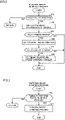
- Fig. 2 is a flowchart showing one example procedure for the calculation unit 40 to plan the freeze inhibiting process.
- the calculation unit 40 determines whether the vehicle 1 is left stopped, based on the stop information input to the input portion T3 (step S10). Note that when the vehicle 1 is left stopped, the electromagnetic relay 10 is opened and the supply of power to the electric load 3 is interrupted, as described above. If the vehicle 1 is not left stopped (NO in step S10), the calculation unit 40 skips the subsequent processes and returns the process.
- step S10 If the vehicle 1 is left stopped (YES in step S10), the calculation unit 40 obtains the positional information of the vehicle 1 input to the input portion T1, as the positional information of the electromagnetic relay 10 (step S11).
- the calculation unit 40 identifies the location region of the electromagnetic relay 10 based on the obtained positional information of the vehicle 1, and references to the freeze region information stored in the storage unit 50 to determine whether the identified location region of the electromagnetic relay 10 is a relay-freeze region (step S12).
- the calculation unit 40 obtains the date/time information input to the input portion T2 (step S13). The calculation unit 40 then identifies the current season based on the obtained date/time information, and references to the freeze region information stored in the storage unit 50 to determine whether the identified current season is a relay-freeze season for the location region of the electromagnetic relay 10 (step S 14).
- the calculation unit 40 sets the timing to perform the freeze inhibiting process (step S15). For example, the calculation unit 40 plans the timing to perform the freeze inhibiting process so that the electromagnetic relay 10 is repeatedly opened and closed for a predetermined duration (e.g., a few minutes) after the elapse of a predetermined time period (e.g., a few hours) since the vehicle 1 has been left stopped.
- a predetermined duration e.g., a few minutes
- a predetermined time period e.g., a few hours
- the electromagnetic relay 10 may be repeatedly opened and closed for a predetermined duration each time a predetermined time period elapses since the vehicle 1 has been left stopped. At this time, the maximum number of times the electromagnetic relay 10 is opened and closed each time the vehicle 1 is left stopped, may be limited in order to prevent excessive power consumption while the vehicle 1 is being left stopped.
- the calculation unit 40 may go to sleep until the next freeze inhibiting process timing, and the calculation unit 40 may be timer-activated at that next freeze inhibiting process timing.
- Fig. 3 is a flowchart showing one example procedure for the calculation unit 40 to perform the freeze inhibiting process that is planned by the processing of Fig. 2 .
- the calculation unit 40 determines whether it is the timing to perform the freeze inhibiting process set in step S15 of Fig. 2 (step S20). For example, in step S15 of Fig. 2 , if the freeze inhibiting process timing is set to a time at which a predetermined time period elapses since the vehicle 1 has been left stopped, the calculation unit 40, in step S20, determines whether the elapsed time since the vehicle 1 has been left stopped, reaches a predetermined time period.
- step S20 If it is not the timing to perform the freeze inhibiting process (NO in step S20), the calculation unit 40 skips the subsequent processes and returns the process.
- the calculation unit 40 performs the freeze inhibiting process (step S21). For example, as the freeze inhibiting process, the calculation unit 40 repeatedly opens and closes the electromagnetic relay 10 for a predetermined duration (e.g., a few minutes), thereby causing the electromagnetic relay 10 to vibrate.
- a predetermined duration e.g., a few minutes
- the control unit 30 includes: the input portion T1 which receives input of the positional information of the vehicle 1; the calculation unit 40 for generating the control signal for controlling the electromagnetic relay 10; and the output portion T4 which outputs the control signal to the electromagnetic relay 10.
- the calculation unit 40 determines whether the location region of the electromagnetic relay 10, identified by the positional information of the vehicle 1, is a relay-freeze region. If the location region of the electromagnetic relay 10 is a relay-freeze region, the calculation unit 40 performs the freeze inhibiting process of opening and closing the electromagnetic relay 10 to cause the electromagnetic relay 10 to vibrate and thereby prevents the electromagnetic relay 10 from being frozen or defrosts the electromagnetic relay 10.
- the electromagnetic relay 10 rather than detecting that the electromagnetic relay 10 is actually frozen by measuring the temperature or a state of electrical discontinuity of the electromagnetic relay 10, it is detected, based on the positional information of the vehicle 1 which includes the electromagnetic relay 10, that the electromagnetic relay 10 is likely to be frozen. If the electromagnetic relay 10 is detected to be likely to be frozen, the freeze inhibiting process is performed before the electromagnetic relay 10 is actually frozen. For this reason, the electromagnetic relay 10 can be prevented from being frozen. For this reason, the number of times or the duration that the electromagnetic relay 10 is required to be vibrated to inhibit the electromagnetic relay 10 from being frozen can be reduced, as compared to, for example, the case where the freeze inhibiting process is performed after the electromagnetic relay 10 is actually frozen and the ice is hardened.
- the electromagnetic relay 10 can be defrosted through the freeze inhibiting process. As a result, in the present embodiment, the electromagnetic relay 10 can be prevented from being frozen or defrosted, without having to provide a temperature sensor for detecting the temperature of the electromagnetic relay 10 and a voltage sensor for detecting a state of electrical discontinuity of the electromagnetic relay 10.
- the calculation unit 40 further determines whether the current season is a relay-freeze season in the relay-freeze region. If the location region of the electromagnetic relay 10 is the relay-freeze region and the current season is the relay-freeze season, the calculation unit 40 performs the freeze inhibiting process.
- whether to perform the freeze inhibiting process is determined, taking into an account not only the location region of the electromagnetic relay 10, but also the current season. For this reason, the determination can be made appropriately as to whether the freeze inhibiting process is needed, and the timing to perform the freeze inhibiting process.
- Fig. 4 is a diagram schematically showing one example configuration of a vehicle 1A which includes a freeze inhibiting apparatus according to Variation 1 of the present embodiment.
- the vehicle 1A is the same as the vehicle 1 described above, except for additionally including a communication device 7, and a control unit 30A instead of the control unit 30.
- the other configuration of the vehicle 1A is the same as the vehicle 1, and the detailed description will therefore not be repeated here.
- the communication device 7 is wirelessly communicable with a web server 8 provided outside the vehicle 1, and downloads weather forecast information from the web server 8.
- the weather forecast information includes the forecast information about the temperature and the humidity of a respective region.
- the weather forecast information at least includes the information about the minimum temperature of a respective region within a predetermined time period (e.g., twelve hours) from the present time.
- the control unit 30A is the same as the control unit 30 described above, except for additionally including an input portion T5 (a second input portion), and a calculation unit 40A instead of the calculation unit 40.
- the input portion T5 is an input port for obtaining the weather forecast information downloaded by the communication device 7 from the web server 8.
- the calculation unit 40A plans the freeze inhibiting process based on the weather forecast information input to the input portion T5.
- Fig. 5 is a flowchart showing one example procedure for the calculation unit 40A to plan the freeze inhibiting process. Note that the steps shown in Fig. 5 having the same numbers as those shown in Fig. 2 have been described already. Therefore, the description will not be repeated here.
- step S10 If the vehicle 1 is left stopped (YES in step S10), the calculation unit 40A obtains the positional information of the vehicle 1 input to the input portion T1, as the positional information of the electromagnetic relay 10 (step S11).
- the calculation unit 40 obtains, via the web server 8, the weather forecast information of the identified location region of the electromagnetic relay 10 (step S16).
- the weather forecast information includes the information about the minimum temperature of the identified location region of the electromagnetic relay 10 within a predetermined time period (e.g., twelve hours) from the present time, as described above.
- the calculation unit 40A determines whether a specific period of time, in which the minimum temperature is less than or equal to a threshold (e.g., below freezing, or a few degrees Celsius higher than below freezing), is present within the predetermined time period from the present time, (step S17).
- a threshold e.g., below freezing, or a few degrees Celsius higher than below freezing
- the calculation unit 40A sets the timing to perform the freeze inhibiting process (step S18). For example, the calculation unit 40A plans the timing to perform the freeze inhibiting process so that the electromagnetic relay 10 is repeatedly opened and closed for a predetermined duration (e.g., a few seconds) in a predetermined time period that includes the specific period of time in which the minimum temperature is less than or equal to the threshold.
- a predetermined duration e.g., a few seconds
- the calculation unit 40A may determine whether to set the timing to perform the freeze inhibiting process, based on the positional information of the vehicle 1 input to the input portion T1 and the weather forecast information input to the input portion T5.
- the approach to prevent the electromagnetic relay 10 from being frozen or defrost the electromagnetic relay 10 is not limited to causing the electromagnetic relay 10 to vibrate by the opening and closing operations of the electromagnetic relay 10.
- a dedicated vibrator may be provided in the vicinity of the electromagnetic relay 10 and the electromagnetic relay 10 may be vibrated by the vibrator.
- the electromagnetic relay 10 may be prevented from being frozen or defrosted by applying to the electromagnetic relay 10 a voltage that is higher than the excitation voltage typically applied to the electromagnetic relay 10.
- the electromagnetic relay 10 may also be prevented from being frozen or defrosted by generation of heat by applying to the electromagnetic relay 10 a voltage that is low to an extent that a normal switching operation is not performed or by applying a voltage to the electromagnetic relay 10 for a short time.
- a heater may also be provided in the vicinity the electromagnetic relay 10 and the electromagnetic relay 10 may be defrosted or prevented from being frozen by heating the electromagnetic relay 10 with the heater.
- a fan may also be provided in the vicinity the electromagnetic relay 10, and the electromagnetic relay 10 may be defrosted or prevented from being frozen by blowing an air at the electromagnetic relay 10 with the fan.
- the electromagnetic relay 10 may be used in conjunction with the air-conditioner of the vehicle 1 to increase the temperature inside the vehicle 1, and the electromagnetic relay 10 may thereby be prevented from being frozen or may be defrosted.
- a user of the vehicle 1 may manually change (i) a specific period of time per run of the freeze inhibiting process, (ii) the number of times the freeze inhibiting process is performed, and (iii) the time intervals at which the freeze inhibiting process is performed.
- the freeze inhibiting process may be planned so that the freeze inhibiting process is performed more frequently in the cold-climate-area mode than in the normal mode.
Landscapes
- Physics & Mathematics (AREA)
- Electromagnetism (AREA)
- Traffic Control Systems (AREA)
- Mobile Radio Communication Systems (AREA)
- Relay Circuits (AREA)
- Electromagnets (AREA)
Abstract
Description
- This nonprovisional application is based on
Japanese Patent Application No. 2020-177759 filed on October 23, 2020 - The present disclosure relates to a technology for inhibiting an electromagnetic relay from being frozen.
- An electromagnetic relay switches in response to a movable terminal being displaced relative to a stationary terminal due to electromagnetic induction of an exciting coil. Such an electromagnetic relay is connected between the electric load and a power supply of a vehicle, for example, and used as a switch for toggling between supplying and shutting off the supply of a power to the electric load.
- In particular, an electromagnetic relay that is mounted on a vehicle may be frozen under the environment in which the outside air temperature is low, such as early in the morning. As the electromagnetic relay being frozen as such hinders the connection between contact points of the movable terminal and the stationary terminal, the electromagnetic relay cannot exercise its function as a switch. Against this, some provision is demanded to be made.
-
Japanese Patent Laying-Open No. 2007-165406 - However, the apparatus disclosed in
Japanese Patent Laying-Open No. 2007-165406 - The present disclosure is made to solve the above problem, and an object of the present disclosure is to prevent the electromagnetic relay from being frozen or defrost the electromagnetic relay, without requiring a temperature sensor for detecting the temperature of the electromagnetic relay and a voltage sensor for detecting a state of electrical discontinuity of the electromagnetic relay.
- An apparatus for inhibiting an electromagnetic relay from being frozen according to the present disclosure includes: a first input portion that receives relay position information which allows identification of a location region of an electromagnetic relay; a calculation unit that generates a control signal for controlling the electromagnetic relay; and an output portion that outputs the control signal to the electromagnetic relay, wherein the calculation unit: determines whether the location region of the electromagnetic relay, identified by the relay position information, is a freeze region in which the electromagnetic relay is likely to be frozen; and performs a freeze inhibiting process for preventing the electromagnetic relay from being frozen or defrosting the electromagnetic relay, when the location region the electromagnetic relay is the freeze region.
- A method for inhibiting an electromagnetic relay from being frozen according to the present disclosure includes: obtaining relay position information which allows identification of a location region of an electromagnetic relay; determining whether the location region of the electromagnetic relay, identified by the relay position information, is a freeze region in which the electromagnetic relay is likely to be frozen; and performing a freeze inhibiting process for preventing the electromagnetic relay from being frozen or defrosting the electromagnetic relay, when the location region of the electromagnetic relay is the freeze region.
- The foregoing and other objects, features, aspects and advantages of the present invention will become more apparent from the following detailed description of the present invention when taken in conjunction with the accompanying drawings.
-
-
Fig. 1 is a diagram (Part 1) schematically showing one example configuration of a vehicle which includes a freeze inhibiting apparatus. -
Fig. 2 is a flowchart (Part 1) showing one example procedure for the calculation unit to plan a freeze inhibiting process. -
Fig. 3 is a flowchart showing one example procedure for the calculation unit to perform the freeze inhibiting process. -
Fig. 4 is a diagram (Part 2) schematically showing one example configuration of a vehicle which includes the freeze inhibiting apparatus. -
Fig. 5 is a flowchart (Part 2) showing one example procedure for the calculation unit to plan the freeze inhibiting process. - Hereinafter, an embodiment according to the present disclosure will be described, with reference to the accompanying drawings. Note that the same reference sign is used to refer to the same or corresponding parts, and the description thereof will not be repeated.
-
Fig. 1 is a diagram schematically showing one example configuration of avehicle 1 which includes a freeze inhibiting apparatus according to the present embodiment. - The
vehicle 1 includes apower supply system 2, anelectric load 3, a positionalinformation acquisition device 4, a date/timeinformation acquisition device 5, and a stopinformation acquisition device 6. Thepower supply system 2 includes anelectromagnetic relay 10, apower supply 20, and acontrol unit 30. Note that thecontrol unit 30 corresponds to one example of a "freeze inhibiting apparatus" according to the present disclosure. - The positional
information acquisition device 4 measures or externally obtains the positional information of thevehicle 1 and outputs it to thecontrol unit 30. The positional information of thevehicle 1, measured or obtained by the positionalinformation acquisition device 4, may be any information insofar as it allows identification of the country or region in which thevehicle 1 is located. Accordingly, the positional information of thevehicle 1, measured or obtained by the positionalinformation acquisition device 4, may be information that indicates the country and region itself in which thevehicle 1 is located, or information indicating the latitude and the longitude of the location of thevehicle 1. - In the present embodiment, an already-available car navigation device equipped with a GPS (global positioning system), previously provided in the
vehicle 1, is diverted as the positionalinformation acquisition device 4. Accordingly, in the present embodiment, information indicating the latitude, longitude, altitude of the location of thevehicle 1 is used as the positional information of thevehicle 1. - Note that the positional
information acquisition device 4 is not limited to a car navigation device, and may be equipment that includes location measurement capabilities by GPS (such as a drive recorder, a radar detector, a mobile terminal that is held by a user of the vehicle 1), for example. The positionalinformation acquisition device 4 may also be equipment that uses a wireless LAN base station, such as a cellular tower and Wi-Fi (registered trademark), airwaves, beacons, vehicle-to-vehicle communications, etc. to obtain the positional information of thevehicle 1. The positionalinformation acquisition device 4 may also be a service center that knows the location of thevehicle 1 if thevehicle 1 includes capabilities for communicating with such a service center. - The date/time
information acquisition device 5 measures or externally obtains the current date/time information (date and time), and outputs it to thecontrol unit 30. The information, obtained by the date/timeinformation acquisition device 5, may be information about the current date, or information about a season (the spring, the summer, the fall, the winter) that the current date belongs to. - In the present embodiment, an already-available car navigation device equipped with GPS are diverted as the date/time
information acquisition device 5 in the same way as the positionalinformation acquisition device 4 described above. Note that the date/timeinformation acquisition device 5 is not limited to a car navigation device, and may be equipment that uses a cellular tower, airwaves, etc. to obtain the date/time information. The date/timeinformation acquisition device 5 can also be omitted if thecontrol unit 30 included in thepower supply system 2 is equipped with the clock function for measuring the current date/time. - The stop
information acquisition device 6 obtains stop information that allows determination as to whether thevehicle 1 is stopped (referred to as being "left stopped") while the control system for thevehicle 1 is stopped. For example, the stopinformation acquisition device 6 can be configured of a starter key or a start button for switching between the activation and deactivation of the control system included in thevehicle 1. - The
electric load 3 is equipment that is activated by a power supplied from thepower supply system 2. For example, theelectric load 3 is a motor which generates a power for driving thevehicle 1. - The
power supply system 2 supplies or shuts off the supply of power to theelectric load 3. Thepower supply system 2 includes theelectromagnetic relay 10, thepower supply 20, and thecontrol unit 30, as described above. - The
electromagnetic relay 10 includes anexciting coil 11, ayoke 12, acore 13, amovable terminal 15, and a pair ofstationary terminals 16. Theexciting coil 11 is wound on a bobbin or the like. Theyoke 12 covers the perimeter of theexciting coil 11, and forms a magnetic circuit when theexciting coil 11 is energized. Thecore 13 is disposed inside theyoke 12, passing through the center of the turns of theexciting coil 11. Themovable terminal 15 is secured to thecore 13 via an insulating member not shown. The pair ofstationary terminals 16 are disposed, each facing themovable terminal 15. - The components of the
electromagnetic relay 10 are accommodated inside thehousing 17, except for a portion of thestationary terminals 16 being exposed outside thehousing 17. One of thestationary terminals 16 is electrically connected to thepower supply 20, and the other one of which is electrically connected to theelectric load 3. - When the
exciting coil 11 is not energized, thecore 13 is biased downward inFig. 1 (the direction away from the stationary terminals 16) by a force not shown, such as a spring, ending up with themovable terminal 15 secured to thecore 13 being separated from thestationary terminals 16 as shown inFig. 1 . This electrically disconnects thepower supply 20 and theelectric load 3 from each other, shutting off the supply of power to theelectric load 3. - In contrast, when the
exciting coil 11 is energized, electromagnetic induction of theexciting coil 11 generates a magnetic field, which forms a magnetic circuit between theyoke 12 and thecore 13, exerting a force that moves thecore 13 upward inFig. 1 (the direction toward the stationary terminals 16) against the bias of the spring. As thecore 13 moves upward inFig. 1 , themovable terminal 15 secured to thecore 13 comes into contact with thestationary terminals 16. This electrically connects thepower supply 20 and theelectric load 3, causing a power to be supplied to theelectric load 3. - The
control unit 30 includes input portions T1, T2, and T3, an output portion T4, acalculation unit 40, and astorage unit 50. - The input portion T1 (a first input portion) is an input port for obtaining the positional information of the
vehicle 1 from the positionalinformation acquisition device 4. The input portion T2 is an input port for obtaining the current date/time information from the date/timeinformation acquisition device 5. The input portion T3 is an input port for obtaining the stop information from the stopinformation acquisition device 6. The input portions T1 to T3 are connected to thecalculation unit 40. The information input to the input portions T1 to T3 are sent to thecalculation unit 40. - The output portion T4 is an output port connected to the
calculation unit 40 and theelectromagnetic relay 10, and for outputting a control signal generated by thecalculation unit 40 to theelectromagnetic relay 10. - The
storage unit 50 is a storage medium that is connected to thecalculation unit 40, and for storing information and programs that are used for calculations by thecalculation unit 40. Thestorage unit 50 may be configured of a storage element, such as a read only memory (ROM) and a random access memory (RAM), etc. - The
calculation unit 40 is connected to the input portions T1 to T3, the output portion T4, and thestorage unit 50. Thecalculation unit 40 is configured of a central processing unit (CPU), for example. Based on signals input to the input portions T1 to T3 and the information and programs stored in thestorage unit 50, thecalculation unit 40 generates a control signal for controlling theelectromagnetic relay 10, and outputs the control signal through the output portion T4 to theelectromagnetic relay 10. This causes theelectromagnetic relay 10 to be controlled in a mode in response to the control signal generated by thecalculation unit 40. - The processing by the
calculation unit 40 is performed by software processing, that is, by thecalculation unit 40 reading and executing the programs stored in thestorage unit 50. Note that the processing by thecalculation unit 40 is not limited to the software processing, and may be performed using dedicated hardware (the electronic circuit). - While the control system of the
vehicle 1 is being activated, thecalculation unit 40 performs a process for energizing theexciting coil 11, thereby closing theelectromagnetic relay 10 and supplying a power to theelectric load 3. In contrast, while the control system of thevehicle 1 is being deactivated, thecalculation unit 40 performs a process for de-energizing theexciting coil 11, thereby opening theelectromagnetic relay 10 and shutting off the supply of power to theelectric load 3. - For example, due to demand on a car layout, the
electromagnetic relay 10 can be disposed in thevehicle 1 at a location where temperature changes and humidity changes are relatively great, such as underneath the floor of thevehicle 1. If theelectromagnetic relay 10 is disposed underneath the floor of thevehicle 1, for example, in a cold climate area or environment in which the outside air temperature is extremely low, such as early in the morning, moisture in the air or the like is built up and frozen on the components of theelectromagnetic relay 10 inside thehousing 17. In particular, since a portion of thestationary terminals 16 is exposed to the outside air external to thehousing 17, as the outside air temperature goes down to a cryogenic temperature, a layer of ice may be formed, covering a contact surface of thestationary terminals 16 with themovable terminal 15. In this case, a poor contact may be caused between thestationary terminals 16 and themovable terminal 15 when theexciting coil 11 is energized, preventing theelectromagnetic relay 10 from appropriately exercising its function as a switch. It is desired that some measures be taken to prevent such a poor contact due to theelectromagnetic relay 10 being frozen. - As one of the measures, for example, it is contemplated to measure the temperature or a state of electrical discontinuity of the
electromagnetic relay 10 to determine whether freezing is actually occurred in theelectromagnetic relay 10, and, if freezing is determined to be occurred in theelectromagnetic relay 10, repeatedly open and close theelectromagnetic relay 10 to cause theelectromagnetic relay 10 to vibrate, thereby defrosting theelectromagnetic relay 10. - However, in order to determine whether freezing is occurred in the
electromagnetic relay 10, the above approach requires a temperature sensor for detecting the temperature of theelectromagnetic relay 10 and a voltage sensor for detecting a state of electrical discontinuity of theelectromagnetic relay 10. Thus, problems, such as an increased size of thepower supply system 2 and an increased cost, can result. - Thus, the
control unit 30 according to the present embodiment is configured to perform a process for preventing theelectromagnetic relay 10 from being frozen or defrosting the electromagnetic relay 10 (hereinafter, also referred to as a "freeze inhibiting process"), without requiring the temperature sensor for detecting the temperature of theelectromagnetic relay 10 and the voltage sensor for detecting a state of electrical discontinuity of theelectromagnetic relay 10. - Specifically, the
storage unit 50, included in thecontrol unit 30, pre-stores freeze region information defining (i) a region (also referred to as a "relay-freeze region") in which theelectromagnetic relay 10 may be frozen and (ii) a season (referred to as a "relay-freeze season") during which theelectromagnetic relay 10 is subjected to freezing in each relay-freeze region. For example, "Hokkaido region, Japan" is registered to the freeze region information as a relay-freeze region, and "January to February (the winter)" is registered as a relay-freeze season of that region. In addition, "Northeast China" may be registered to the freeze region information as a relay-freeze region, and "December to March (the winter)" may be registered as a relay-freeze season for that region. - The
calculation unit 40 includes a freezeregion determination unit 41 and afreeze inhibiting processor 42. When thevehicle 1 is determined to be left stopped based on the stop information input to the input portion T3, the freezeregion determination unit 41 identifies the location region of theelectromagnetic relay 10 based on the positional information of thevehicle 1 input to the input portion T1, and identifies the current season based on the date/time information input to the input portion T2. The freezeregion determination unit 41 then references to the freeze region information stored in thestorage unit 50 to determine whether the identified location region of theelectromagnetic relay 10 is a relay-freeze region, and whether the identified current season is a relay-freeze season. - If the freeze
region determination unit 41 determines that the location region of theelectromagnetic relay 10 is a relay-freeze region and the current season is a relay-freeze season, thefreeze inhibiting processor 42 repeatedly opens and closes theelectromagnetic relay 10 at a predetermined timing for a predetermined duration, thereby causing theelectromagnetic relay 10 to vibrate. The vibration of theelectromagnetic relay 10 peripherally disperses the moisture built up on a contact surface of thestationary terminals 16 with themovable terminal 15 or a contact surface of themovable terminal 15 with thestationary terminals 16, making a layer of ice less likely to be formed between themovable terminal 15 and thestationary terminals 16. As a result, theelectromagnetic relay 10 can be prevented from being frozen, without requiring the temperature sensor for detecting the temperature of theelectromagnetic relay 10 or the voltage sensor for detecting a state of electrical discontinuity of theelectromagnetic relay 10. If theelectromagnetic relay 10 is already frozen, theelectromagnetic relay 10 can be defrosted by its vibration. -
Fig. 2 is a flowchart showing one example procedure for thecalculation unit 40 to plan the freeze inhibiting process. - The
calculation unit 40 determines whether thevehicle 1 is left stopped, based on the stop information input to the input portion T3 (step S10). Note that when thevehicle 1 is left stopped, theelectromagnetic relay 10 is opened and the supply of power to theelectric load 3 is interrupted, as described above. If thevehicle 1 is not left stopped (NO in step S10), thecalculation unit 40 skips the subsequent processes and returns the process. - If the
vehicle 1 is left stopped (YES in step S10), thecalculation unit 40 obtains the positional information of thevehicle 1 input to the input portion T1, as the positional information of the electromagnetic relay 10 (step S11). - Next, the
calculation unit 40 identifies the location region of theelectromagnetic relay 10 based on the obtained positional information of thevehicle 1, and references to the freeze region information stored in thestorage unit 50 to determine whether the identified location region of theelectromagnetic relay 10 is a relay-freeze region (step S12). - If the location region of the
electromagnetic relay 10 is a relay-freeze region (YES in step S12), thecalculation unit 40 obtains the date/time information input to the input portion T2 (step S13). Thecalculation unit 40 then identifies the current season based on the obtained date/time information, and references to the freeze region information stored in thestorage unit 50 to determine whether the identified current season is a relay-freeze season for the location region of the electromagnetic relay 10 (step S 14). - If the current season is a relay-freeze season (YES in step S14), the
calculation unit 40 sets the timing to perform the freeze inhibiting process (step S15). For example, thecalculation unit 40 plans the timing to perform the freeze inhibiting process so that theelectromagnetic relay 10 is repeatedly opened and closed for a predetermined duration (e.g., a few minutes) after the elapse of a predetermined time period (e.g., a few hours) since thevehicle 1 has been left stopped. - Note that, in order to certainly defrost the
electromagnetic relay 10, theelectromagnetic relay 10 may be repeatedly opened and closed for a predetermined duration each time a predetermined time period elapses since thevehicle 1 has been left stopped. At this time, the maximum number of times theelectromagnetic relay 10 is opened and closed each time thevehicle 1 is left stopped, may be limited in order to prevent excessive power consumption while thevehicle 1 is being left stopped. - After the timing to perform the freeze inhibiting process is set in step S15, the
calculation unit 40 may go to sleep until the next freeze inhibiting process timing, and thecalculation unit 40 may be timer-activated at that next freeze inhibiting process timing. -
Fig. 3 is a flowchart showing one example procedure for thecalculation unit 40 to perform the freeze inhibiting process that is planned by the processing ofFig. 2 . - Initially, the
calculation unit 40 determines whether it is the timing to perform the freeze inhibiting process set in step S15 ofFig. 2 (step S20). For example, in step S15 ofFig. 2 , if the freeze inhibiting process timing is set to a time at which a predetermined time period elapses since thevehicle 1 has been left stopped, thecalculation unit 40, in step S20, determines whether the elapsed time since thevehicle 1 has been left stopped, reaches a predetermined time period. - If it is not the timing to perform the freeze inhibiting process (NO in step S20), the
calculation unit 40 skips the subsequent processes and returns the process. - If it is the timing to perform the freeze inhibiting process (YES in step S20), the
calculation unit 40 performs the freeze inhibiting process (step S21). For example, as the freeze inhibiting process, thecalculation unit 40 repeatedly opens and closes theelectromagnetic relay 10 for a predetermined duration (e.g., a few minutes), thereby causing theelectromagnetic relay 10 to vibrate. - As described above, the
control unit 30 according to the present embodiment includes: the input portion T1 which receives input of the positional information of thevehicle 1; thecalculation unit 40 for generating the control signal for controlling theelectromagnetic relay 10; and the output portion T4 which outputs the control signal to theelectromagnetic relay 10. Thecalculation unit 40 determines whether the location region of theelectromagnetic relay 10, identified by the positional information of thevehicle 1, is a relay-freeze region. If the location region of theelectromagnetic relay 10 is a relay-freeze region, thecalculation unit 40 performs the freeze inhibiting process of opening and closing theelectromagnetic relay 10 to cause theelectromagnetic relay 10 to vibrate and thereby prevents theelectromagnetic relay 10 from being frozen or defrosts theelectromagnetic relay 10. - According to the above configuration, rather than detecting that the
electromagnetic relay 10 is actually frozen by measuring the temperature or a state of electrical discontinuity of theelectromagnetic relay 10, it is detected, based on the positional information of thevehicle 1 which includes theelectromagnetic relay 10, that theelectromagnetic relay 10 is likely to be frozen. If theelectromagnetic relay 10 is detected to be likely to be frozen, the freeze inhibiting process is performed before theelectromagnetic relay 10 is actually frozen. For this reason, theelectromagnetic relay 10 can be prevented from being frozen. For this reason, the number of times or the duration that theelectromagnetic relay 10 is required to be vibrated to inhibit theelectromagnetic relay 10 from being frozen can be reduced, as compared to, for example, the case where the freeze inhibiting process is performed after theelectromagnetic relay 10 is actually frozen and the ice is hardened. If theelectromagnetic relay 10 is already being frozen, theelectromagnetic relay 10 can be defrosted through the freeze inhibiting process. As a result, in the present embodiment, theelectromagnetic relay 10 can be prevented from being frozen or defrosted, without having to provide a temperature sensor for detecting the temperature of theelectromagnetic relay 10 and a voltage sensor for detecting a state of electrical discontinuity of theelectromagnetic relay 10. - In particular, the
calculation unit 40 according to the present embodiment further determines whether the current season is a relay-freeze season in the relay-freeze region. If the location region of theelectromagnetic relay 10 is the relay-freeze region and the current season is the relay-freeze season, thecalculation unit 40 performs the freeze inhibiting process. - According to the above configuration, whether to perform the freeze inhibiting process is determined, taking into an account not only the location region of the
electromagnetic relay 10, but also the current season. For this reason, the determination can be made appropriately as to whether the freeze inhibiting process is needed, and the timing to perform the freeze inhibiting process. -
Fig. 4 is a diagram schematically showing one example configuration of avehicle 1A which includes a freeze inhibiting apparatus according toVariation 1 of the present embodiment. Thevehicle 1A is the same as thevehicle 1 described above, except for additionally including acommunication device 7, and acontrol unit 30A instead of thecontrol unit 30. The other configuration of thevehicle 1A is the same as thevehicle 1, and the detailed description will therefore not be repeated here. - The
communication device 7 is wirelessly communicable with aweb server 8 provided outside thevehicle 1, and downloads weather forecast information from theweb server 8. Note that the weather forecast information includes the forecast information about the temperature and the humidity of a respective region. The weather forecast information at least includes the information about the minimum temperature of a respective region within a predetermined time period (e.g., twelve hours) from the present time. - The
control unit 30A is the same as thecontrol unit 30 described above, except for additionally including an input portion T5 (a second input portion), and a calculation unit 40A instead of thecalculation unit 40. The input portion T5 is an input port for obtaining the weather forecast information downloaded by thecommunication device 7 from theweb server 8. The calculation unit 40A plans the freeze inhibiting process based on the weather forecast information input to the input portion T5. -
Fig. 5 is a flowchart showing one example procedure for the calculation unit 40A to plan the freeze inhibiting process. Note that the steps shown inFig. 5 having the same numbers as those shown inFig. 2 have been described already. Therefore, the description will not be repeated here. - If the
vehicle 1 is left stopped (YES in step S10), the calculation unit 40A obtains the positional information of thevehicle 1 input to the input portion T1, as the positional information of the electromagnetic relay 10 (step S11). - If the location region of the
electromagnetic relay 10, identified based on the obtained positional information of thevehicle 1, is a relay-freeze region (YES in step S12), thecalculation unit 40 obtains, via theweb server 8, the weather forecast information of the identified location region of the electromagnetic relay 10 (step S16). Note that the weather forecast information includes the information about the minimum temperature of the identified location region of theelectromagnetic relay 10 within a predetermined time period (e.g., twelve hours) from the present time, as described above. - Next, based on the weather forecast information obtained in step S16, the calculation unit 40A determines whether a specific period of time, in which the minimum temperature is less than or equal to a threshold (e.g., below freezing, or a few degrees Celsius higher than below freezing), is present within the predetermined time period from the present time, (step S17).
- If the specific period of time is present in which the minimum temperature is less than or equal to the threshold (YES in step S17), the calculation unit 40A sets the timing to perform the freeze inhibiting process (step S18). For example, the calculation unit 40A plans the timing to perform the freeze inhibiting process so that the
electromagnetic relay 10 is repeatedly opened and closed for a predetermined duration (e.g., a few seconds) in a predetermined time period that includes the specific period of time in which the minimum temperature is less than or equal to the threshold. - Note that the procedure which the calculation unit 40A carries out to perform the freeze inhibiting process planed through the processing shown in
Fig. 5 is the same as the procedure described with respect toFig. 3 described above, and the detailed description will therefore not be repeated here. - As described above, the calculation unit 40A may determine whether to set the timing to perform the freeze inhibiting process, based on the positional information of the
vehicle 1 input to the input portion T1 and the weather forecast information input to the input portion T5. - In the embodiment described above, the description has been given with reference to preventing the
electromagnetic relay 10 from being frozen or defrosting theelectromagnetic relay 10 by the opening and closing operations of theelectromagnetic relay 10 and thereby causing theelectromagnetic relay 10 to vibrate in the freeze inhibiting process. - However, the approach to prevent the
electromagnetic relay 10 from being frozen or defrost theelectromagnetic relay 10 is not limited to causing theelectromagnetic relay 10 to vibrate by the opening and closing operations of theelectromagnetic relay 10. - For example, a dedicated vibrator may be provided in the vicinity of the
electromagnetic relay 10 and theelectromagnetic relay 10 may be vibrated by the vibrator. - Also, in order to release even a rigid frozen state of the
electromagnetic relay 10, theelectromagnetic relay 10 may be prevented from being frozen or defrosted by applying to the electromagnetic relay 10 a voltage that is higher than the excitation voltage typically applied to theelectromagnetic relay 10. - The
electromagnetic relay 10 may also be prevented from being frozen or defrosted by generation of heat by applying to the electromagnetic relay 10 a voltage that is low to an extent that a normal switching operation is not performed or by applying a voltage to theelectromagnetic relay 10 for a short time. - A heater may also be provided in the vicinity the
electromagnetic relay 10 and theelectromagnetic relay 10 may be defrosted or prevented from being frozen by heating theelectromagnetic relay 10 with the heater. - A fan may also be provided in the vicinity the
electromagnetic relay 10, and theelectromagnetic relay 10 may be defrosted or prevented from being frozen by blowing an air at theelectromagnetic relay 10 with the fan. - If the
electromagnetic relay 10 is disposed within thevehicle 1, theelectromagnetic relay 10 may be used in conjunction with the air-conditioner of thevehicle 1 to increase the temperature inside thevehicle 1, and theelectromagnetic relay 10 may thereby be prevented from being frozen or may be defrosted. - A user of the
vehicle 1 may manually change (i) a specific period of time per run of the freeze inhibiting process, (ii) the number of times the freeze inhibiting process is performed, and (iii) the time intervals at which the freeze inhibiting process is performed. For example, when the user of thevehicle 1 can manually switch control modes between a normal mode and a cold-climate-area mode, the freeze inhibiting process may be planned so that the freeze inhibiting process is performed more frequently in the cold-climate-area mode than in the normal mode. - Although the present invention has been described and illustrated in detail, it is clearly understood that the same is by way of illustration and example only and is not to be taken by way of limitation, the scope of the present invention being interpreted by the terms of the appended claims.
Claims (5)
- An apparatus for inhibiting an electromagnetic relay from being frozen, the apparatus comprising:a first input portion (T1) that receives relay position information which allows identification of a location region of an electromagnetic relay (10);a calculation unit (40) that generates a control signal for controlling the electromagnetic relay (10); andan output portion (T4) that outputs the control signal to the electromagnetic relay (10), whereinthe calculation unit (40):determines whether the location region of the electromagnetic relay (10), identified by the relay position information, is a freeze region in which the electromagnetic relay (10) is likely to be frozen; andperforms a freeze inhibiting process for preventing the electromagnetic relay (10) from being frozen or defrosting the electromagnetic relay (10), when the location region of the electromagnetic relay (10) is the freeze region.
- The apparatus according to claim 1, whereinthe electromagnetic relay (10) is included in a vehicle (1) equipped with a device that obtains vehicle position information, andthe vehicle position information is input to the first input portion (T1), as the relay position information,the apparatus further comprising a storage unit (50) that stores freeze region information defining the freeze region and a freeze season in which the electromagnetic relay (10) is subjected to freezing in the freeze region, whereinthe calculation unit (40):determines whether the location region of the electromagnetic relay (10) is the freeze region, based on the relay position information;determines whether a current season is the freeze season in the freeze region; andperforms the freeze inhibiting process when the location region of the electromagnetic relay (10) is the freeze region and the current season is the freeze season in the freeze region.
- The apparatus according to claim 1, further comprising:a second input portion (T5) that receives weather forecast information from an external server, whereinthe calculation unit (40):determines whether the location region of the electromagnetic relay (10) is the freeze region, based on the relay position information;determines, based on the weather forecast information, whether a specific period of time, in which a minimum temperature is less than or equal to a threshold, is present within a predetermined time period; andperforms the freeze inhibiting process when the location region of the electromagnetic relay (10) is the freeze region and the specific period of time, in which the minimum temperature is less than or equal to the threshold, is present within the predetermined time period.
- The apparatus according to any one of claims 1 to 3, wherein
the calculation unit (40) causes the electromagnetic relay (10) to vibrate by repeatedly opening and closing the electromagnetic relay (10) for a predetermined duration in the freeze inhibiting process. - A method for inhibiting an electromagnetic relay from being frozen, the method comprising:obtaining relay position information which allows identification of a location region of an electromagnetic relay (10);determining whether the location region of the electromagnetic relay (10), identified by the relay position information, is a freeze region in which the electromagnetic relay (10) is likely to be frozen; andperforming a freeze inhibiting process for preventing the electromagnetic relay (10) from being frozen or defrosting the electromagnetic relay (10), when the location region of the electromagnetic relay (10) is the freeze region.
Applications Claiming Priority (1)
| Application Number | Priority Date | Filing Date | Title |
|---|---|---|---|
| JP2020177759A JP2022068927A (en) | 2020-10-23 | 2020-10-23 | Freezing suppression device and freezing suppression method for electromagnetic relay |
Publications (2)
| Publication Number | Publication Date |
|---|---|
| EP3989257A1 true EP3989257A1 (en) | 2022-04-27 |
| EP3989257B1 EP3989257B1 (en) | 2023-05-10 |
Family
ID=77897500
Family Applications (1)
| Application Number | Title | Priority Date | Filing Date |
|---|---|---|---|
| EP21198101.4A Active EP3989257B1 (en) | 2020-10-23 | 2021-09-21 | Apparatus and method for inhibiting electromagnetic relay from being frozen |
Country Status (4)
| Country | Link |
|---|---|
| US (1) | US11594388B2 (en) |
| EP (1) | EP3989257B1 (en) |
| JP (1) | JP2022068927A (en) |
| CN (1) | CN114496653B (en) |
Families Citing this family (2)
| Publication number | Priority date | Publication date | Assignee | Title |
|---|---|---|---|---|
| JP2023042353A (en) * | 2021-09-14 | 2023-03-27 | 株式会社Subaru | Control method for electromagnetic relay, and control device |
| JP2024048420A (en) * | 2022-09-28 | 2024-04-09 | 株式会社Subaru | Relay System |
Citations (5)
| Publication number | Priority date | Publication date | Assignee | Title |
|---|---|---|---|---|
| JP2007165406A (en) | 2005-12-09 | 2007-06-28 | Nissan Motor Co Ltd | Electromagnetic relay freeze release apparatus and freeze release method |
| US20130181732A1 (en) * | 2012-01-13 | 2013-07-18 | Nissan North America, Inc. | Methods of preventing freezing of relays in electrical components |
| US20140340808A1 (en) * | 2011-12-28 | 2014-11-20 | Shiroki Corporation | Drive device for opening/closing body |
| US20150115740A1 (en) * | 2012-12-18 | 2015-04-30 | Nsk Ltd. | Power Supply Relay Controller and Electric Power Steering Apparatus |
| JP2020177759A (en) | 2019-04-16 | 2020-10-29 | 矢崎総業株式会社 | Terminal fastening aid |
Family Cites Families (7)
| Publication number | Priority date | Publication date | Assignee | Title |
|---|---|---|---|---|
| JP3006273B2 (en) * | 1992-03-06 | 2000-02-07 | トヨタ自動車株式会社 | Vehicle motion control device |
| JPH114377A (en) | 1997-06-12 | 1999-01-06 | Agency Of Ind Science & Technol | Digital still camera having moving background elimination mechanism by multiple shutter, its image method and recording medium storing image pickup control program |
| JPH1114377A (en) * | 1997-06-23 | 1999-01-22 | Fuji Heavy Ind Ltd | Road freezing estimating device |
| JP4445523B2 (en) * | 2007-06-26 | 2010-04-07 | 株式会社東芝 | refrigerator |
| JP2009196455A (en) * | 2008-02-20 | 2009-09-03 | Fuji Heavy Ind Ltd | On-vehicle relay control unit |
| JP2019183647A (en) * | 2018-04-02 | 2019-10-24 | 株式会社デンソー | Control device for internal combustion engine |
| JP6641439B1 (en) * | 2018-09-26 | 2020-02-05 | 株式会社Subaru | Electromagnetic relay deicing system |
-
2020
- 2020-10-23 JP JP2020177759A patent/JP2022068927A/en active Pending
-
2021
- 2021-09-21 EP EP21198101.4A patent/EP3989257B1/en active Active
- 2021-10-21 US US17/506,679 patent/US11594388B2/en active Active
- 2021-10-22 CN CN202111230701.0A patent/CN114496653B/en active Active
Patent Citations (5)
| Publication number | Priority date | Publication date | Assignee | Title |
|---|---|---|---|---|
| JP2007165406A (en) | 2005-12-09 | 2007-06-28 | Nissan Motor Co Ltd | Electromagnetic relay freeze release apparatus and freeze release method |
| US20140340808A1 (en) * | 2011-12-28 | 2014-11-20 | Shiroki Corporation | Drive device for opening/closing body |
| US20130181732A1 (en) * | 2012-01-13 | 2013-07-18 | Nissan North America, Inc. | Methods of preventing freezing of relays in electrical components |
| US20150115740A1 (en) * | 2012-12-18 | 2015-04-30 | Nsk Ltd. | Power Supply Relay Controller and Electric Power Steering Apparatus |
| JP2020177759A (en) | 2019-04-16 | 2020-10-29 | 矢崎総業株式会社 | Terminal fastening aid |
Also Published As
| Publication number | Publication date |
|---|---|
| US11594388B2 (en) | 2023-02-28 |
| CN114496653A (en) | 2022-05-13 |
| EP3989257B1 (en) | 2023-05-10 |
| US20220130629A1 (en) | 2022-04-28 |
| JP2022068927A (en) | 2022-05-11 |
| CN114496653B (en) | 2023-10-03 |
Similar Documents
| Publication | Publication Date | Title |
|---|---|---|
| EP3989257B1 (en) | Apparatus and method for inhibiting electromagnetic relay from being frozen | |
| CN103002551B (en) | A kind of electricity saving method of communication terminal | |
| US12093112B2 (en) | Facilitating power conservation for devices based on likelihood of power usage level | |
| US9452720B2 (en) | Telematics master of power | |
| US20220030384A1 (en) | Vehicle control system and vehicle control method | |
| US7843384B2 (en) | Vehicle communication terminal | |
| US20090098880A1 (en) | Mobile terminals and methods for regulating power-on/off of a gps positioning circuit | |
| US20170371060A1 (en) | Method for operating a sensor device, and sensor device | |
| JP2717424B2 (en) | Defrost prevention device for vehicle windshield | |
| JP2012233882A (en) | Global navigation satellite system receiver and control method therefor | |
| US20190202401A1 (en) | Device and method for controlling vehicle | |
| EP2201634A1 (en) | Method and control unit for automatic selection of an operating mode for a vehicle with fuel cells | |
| JP5396376B2 (en) | POSITION INFORMATION MEASURING DEVICE, METHOD, AND PROGRAM | |
| US10624560B2 (en) | Electronic device, and electronic device control method | |
| EP3808112B1 (en) | Power saving for device tracking | |
| KR20220057399A (en) | Chassis-controlling IoT terminal and method and system for controlling location of chassis by using the IoT terminal | |
| JP3905680B2 (en) | Mobile system | |
| KR20130074371A (en) | Localization system and the method thereof | |
| JPH1182263A (en) | Unattended engine starter | |
| KR101122619B1 (en) | Supervisory system for electronic mine using global positioning system satellite | |
| WO2022224707A1 (en) | Method for controlling power source of vehicle, and computer program for vehicle | |
| US20230268525A1 (en) | Predictive freeze preparation scheduling for fuel cell propulsion system | |
| JP2004093401A (en) | Navigation system for automobile | |
| JP2008058203A (en) | Location information terminal and location management center | |
| JP2004279314A (en) | Information terminal device, control method of information terminal device, control program of information terminal device, computer-readable recording medium recording control program of information terminal device |
Legal Events
| Date | Code | Title | Description |
|---|---|---|---|
| PUAI | Public reference made under article 153(3) epc to a published international application that has entered the european phase |
Free format text: ORIGINAL CODE: 0009012 |
|
| STAA | Information on the status of an ep patent application or granted ep patent |
Free format text: STATUS: REQUEST FOR EXAMINATION WAS MADE |
|
| 17P | Request for examination filed |
Effective date: 20210921 |
|
| AK | Designated contracting states |
Kind code of ref document: A1 Designated state(s): AL AT BE BG CH CY CZ DE DK EE ES FI FR GB GR HR HU IE IS IT LI LT LU LV MC MK MT NL NO PL PT RO RS SE SI SK SM TR |
|
| RAP3 | Party data changed (applicant data changed or rights of an application transferred) |
Owner name: PRIME PLANET ENERGY & SOLUTIONS, INC. |
|
| GRAP | Despatch of communication of intention to grant a patent |
Free format text: ORIGINAL CODE: EPIDOSNIGR1 |
|
| STAA | Information on the status of an ep patent application or granted ep patent |
Free format text: STATUS: GRANT OF PATENT IS INTENDED |
|
| RIC1 | Information provided on ipc code assigned before grant |
Ipc: H01H 47/00 20060101AFI20221024BHEP |
|
| INTG | Intention to grant announced |
Effective date: 20221121 |
|
| GRAS | Grant fee paid |
Free format text: ORIGINAL CODE: EPIDOSNIGR3 |
|
| GRAA | (expected) grant |
Free format text: ORIGINAL CODE: 0009210 |
|
| STAA | Information on the status of an ep patent application or granted ep patent |
Free format text: STATUS: THE PATENT HAS BEEN GRANTED |
|
| AK | Designated contracting states |
Kind code of ref document: B1 Designated state(s): AL AT BE BG CH CY CZ DE DK EE ES FI FR GB GR HR HU IE IS IT LI LT LU LV MC MK MT NL NO PL PT RO RS SE SI SK SM TR |
|
| REG | Reference to a national code |
Ref country code: GB Ref legal event code: FG4D |
|
| REG | Reference to a national code |
Ref country code: AT Ref legal event code: REF Ref document number: 1567556 Country of ref document: AT Kind code of ref document: T Effective date: 20230515 Ref country code: CH Ref legal event code: EP |
|
| REG | Reference to a national code |
Ref country code: DE Ref legal event code: R096 Ref document number: 602021002310 Country of ref document: DE |
|
| REG | Reference to a national code |
Ref country code: IE Ref legal event code: FG4D |
|
| P01 | Opt-out of the competence of the unified patent court (upc) registered |
Effective date: 20230510 |
|
| REG | Reference to a national code |
Ref country code: LT Ref legal event code: MG9D |
|
| REG | Reference to a national code |
Ref country code: NL Ref legal event code: MP Effective date: 20230510 |
|
| REG | Reference to a national code |
Ref country code: AT Ref legal event code: MK05 Ref document number: 1567556 Country of ref document: AT Kind code of ref document: T Effective date: 20230510 |
|
| PG25 | Lapsed in a contracting state [announced via postgrant information from national office to epo] |
Ref country code: SE Free format text: LAPSE BECAUSE OF FAILURE TO SUBMIT A TRANSLATION OF THE DESCRIPTION OR TO PAY THE FEE WITHIN THE PRESCRIBED TIME-LIMIT Effective date: 20230510 Ref country code: PT Free format text: LAPSE BECAUSE OF FAILURE TO SUBMIT A TRANSLATION OF THE DESCRIPTION OR TO PAY THE FEE WITHIN THE PRESCRIBED TIME-LIMIT Effective date: 20230911 Ref country code: NO Free format text: LAPSE BECAUSE OF FAILURE TO SUBMIT A TRANSLATION OF THE DESCRIPTION OR TO PAY THE FEE WITHIN THE PRESCRIBED TIME-LIMIT Effective date: 20230810 Ref country code: NL Free format text: LAPSE BECAUSE OF FAILURE TO SUBMIT A TRANSLATION OF THE DESCRIPTION OR TO PAY THE FEE WITHIN THE PRESCRIBED TIME-LIMIT Effective date: 20230510 Ref country code: ES Free format text: LAPSE BECAUSE OF FAILURE TO SUBMIT A TRANSLATION OF THE DESCRIPTION OR TO PAY THE FEE WITHIN THE PRESCRIBED TIME-LIMIT Effective date: 20230510 Ref country code: AT Free format text: LAPSE BECAUSE OF FAILURE TO SUBMIT A TRANSLATION OF THE DESCRIPTION OR TO PAY THE FEE WITHIN THE PRESCRIBED TIME-LIMIT Effective date: 20230510 |
|
| PG25 | Lapsed in a contracting state [announced via postgrant information from national office to epo] |
Ref country code: RS Free format text: LAPSE BECAUSE OF FAILURE TO SUBMIT A TRANSLATION OF THE DESCRIPTION OR TO PAY THE FEE WITHIN THE PRESCRIBED TIME-LIMIT Effective date: 20230510 Ref country code: PL Free format text: LAPSE BECAUSE OF FAILURE TO SUBMIT A TRANSLATION OF THE DESCRIPTION OR TO PAY THE FEE WITHIN THE PRESCRIBED TIME-LIMIT Effective date: 20230510 Ref country code: LV Free format text: LAPSE BECAUSE OF FAILURE TO SUBMIT A TRANSLATION OF THE DESCRIPTION OR TO PAY THE FEE WITHIN THE PRESCRIBED TIME-LIMIT Effective date: 20230510 Ref country code: LT Free format text: LAPSE BECAUSE OF FAILURE TO SUBMIT A TRANSLATION OF THE DESCRIPTION OR TO PAY THE FEE WITHIN THE PRESCRIBED TIME-LIMIT Effective date: 20230510 Ref country code: IS Free format text: LAPSE BECAUSE OF FAILURE TO SUBMIT A TRANSLATION OF THE DESCRIPTION OR TO PAY THE FEE WITHIN THE PRESCRIBED TIME-LIMIT Effective date: 20230910 Ref country code: HR Free format text: LAPSE BECAUSE OF FAILURE TO SUBMIT A TRANSLATION OF THE DESCRIPTION OR TO PAY THE FEE WITHIN THE PRESCRIBED TIME-LIMIT Effective date: 20230510 Ref country code: GR Free format text: LAPSE BECAUSE OF FAILURE TO SUBMIT A TRANSLATION OF THE DESCRIPTION OR TO PAY THE FEE WITHIN THE PRESCRIBED TIME-LIMIT Effective date: 20230811 |
|
| PG25 | Lapsed in a contracting state [announced via postgrant information from national office to epo] |
Ref country code: FI Free format text: LAPSE BECAUSE OF FAILURE TO SUBMIT A TRANSLATION OF THE DESCRIPTION OR TO PAY THE FEE WITHIN THE PRESCRIBED TIME-LIMIT Effective date: 20230510 |
|
| PG25 | Lapsed in a contracting state [announced via postgrant information from national office to epo] |
Ref country code: SK Free format text: LAPSE BECAUSE OF FAILURE TO SUBMIT A TRANSLATION OF THE DESCRIPTION OR TO PAY THE FEE WITHIN THE PRESCRIBED TIME-LIMIT Effective date: 20230510 |
|
| PG25 | Lapsed in a contracting state [announced via postgrant information from national office to epo] |
Ref country code: SM Free format text: LAPSE BECAUSE OF FAILURE TO SUBMIT A TRANSLATION OF THE DESCRIPTION OR TO PAY THE FEE WITHIN THE PRESCRIBED TIME-LIMIT Effective date: 20230510 Ref country code: SK Free format text: LAPSE BECAUSE OF FAILURE TO SUBMIT A TRANSLATION OF THE DESCRIPTION OR TO PAY THE FEE WITHIN THE PRESCRIBED TIME-LIMIT Effective date: 20230510 Ref country code: RO Free format text: LAPSE BECAUSE OF FAILURE TO SUBMIT A TRANSLATION OF THE DESCRIPTION OR TO PAY THE FEE WITHIN THE PRESCRIBED TIME-LIMIT Effective date: 20230510 Ref country code: EE Free format text: LAPSE BECAUSE OF FAILURE TO SUBMIT A TRANSLATION OF THE DESCRIPTION OR TO PAY THE FEE WITHIN THE PRESCRIBED TIME-LIMIT Effective date: 20230510 Ref country code: DK Free format text: LAPSE BECAUSE OF FAILURE TO SUBMIT A TRANSLATION OF THE DESCRIPTION OR TO PAY THE FEE WITHIN THE PRESCRIBED TIME-LIMIT Effective date: 20230510 Ref country code: CZ Free format text: LAPSE BECAUSE OF FAILURE TO SUBMIT A TRANSLATION OF THE DESCRIPTION OR TO PAY THE FEE WITHIN THE PRESCRIBED TIME-LIMIT Effective date: 20230510 |
|
| REG | Reference to a national code |
Ref country code: DE Ref legal event code: R097 Ref document number: 602021002310 Country of ref document: DE |
|
| PLBE | No opposition filed within time limit |
Free format text: ORIGINAL CODE: 0009261 |
|
| STAA | Information on the status of an ep patent application or granted ep patent |
Free format text: STATUS: NO OPPOSITION FILED WITHIN TIME LIMIT |
|
| 26N | No opposition filed |
Effective date: 20240213 |
|
| PG25 | Lapsed in a contracting state [announced via postgrant information from national office to epo] |
Ref country code: SI Free format text: LAPSE BECAUSE OF FAILURE TO SUBMIT A TRANSLATION OF THE DESCRIPTION OR TO PAY THE FEE WITHIN THE PRESCRIBED TIME-LIMIT Effective date: 20230510 |
|
| PG25 | Lapsed in a contracting state [announced via postgrant information from national office to epo] |
Ref country code: LU Free format text: LAPSE BECAUSE OF NON-PAYMENT OF DUE FEES Effective date: 20230921 |
|
| REG | Reference to a national code |
Ref country code: BE Ref legal event code: MM Effective date: 20230930 |
|
| PG25 | Lapsed in a contracting state [announced via postgrant information from national office to epo] |
Ref country code: SI Free format text: LAPSE BECAUSE OF FAILURE TO SUBMIT A TRANSLATION OF THE DESCRIPTION OR TO PAY THE FEE WITHIN THE PRESCRIBED TIME-LIMIT Effective date: 20230510 Ref country code: LU Free format text: LAPSE BECAUSE OF NON-PAYMENT OF DUE FEES Effective date: 20230921 Ref country code: IT Free format text: LAPSE BECAUSE OF FAILURE TO SUBMIT A TRANSLATION OF THE DESCRIPTION OR TO PAY THE FEE WITHIN THE PRESCRIBED TIME-LIMIT Effective date: 20230510 Ref country code: MC Free format text: LAPSE BECAUSE OF FAILURE TO SUBMIT A TRANSLATION OF THE DESCRIPTION OR TO PAY THE FEE WITHIN THE PRESCRIBED TIME-LIMIT Effective date: 20230510 |
|
| REG | Reference to a national code |
Ref country code: IE Ref legal event code: MM4A |
|
| PG25 | Lapsed in a contracting state [announced via postgrant information from national office to epo] |
Ref country code: IE Free format text: LAPSE BECAUSE OF NON-PAYMENT OF DUE FEES Effective date: 20230921 |
|
| PG25 | Lapsed in a contracting state [announced via postgrant information from national office to epo] |
Ref country code: IE Free format text: LAPSE BECAUSE OF NON-PAYMENT OF DUE FEES Effective date: 20230921 |
|
| PG25 | Lapsed in a contracting state [announced via postgrant information from national office to epo] |
Ref country code: BE Free format text: LAPSE BECAUSE OF NON-PAYMENT OF DUE FEES Effective date: 20230930 |
|
| PG25 | Lapsed in a contracting state [announced via postgrant information from national office to epo] |
Ref country code: BG Free format text: LAPSE BECAUSE OF FAILURE TO SUBMIT A TRANSLATION OF THE DESCRIPTION OR TO PAY THE FEE WITHIN THE PRESCRIBED TIME-LIMIT Effective date: 20230510 |
|
| PG25 | Lapsed in a contracting state [announced via postgrant information from national office to epo] |
Ref country code: BG Free format text: LAPSE BECAUSE OF FAILURE TO SUBMIT A TRANSLATION OF THE DESCRIPTION OR TO PAY THE FEE WITHIN THE PRESCRIBED TIME-LIMIT Effective date: 20230510 |
|
| REG | Reference to a national code |
Ref country code: CH Ref legal event code: PL |
|
| PG25 | Lapsed in a contracting state [announced via postgrant information from national office to epo] |
Ref country code: CH Free format text: LAPSE BECAUSE OF NON-PAYMENT OF DUE FEES Effective date: 20240930 |
|
| PG25 | Lapsed in a contracting state [announced via postgrant information from national office to epo] |
Ref country code: CY Free format text: LAPSE BECAUSE OF FAILURE TO SUBMIT A TRANSLATION OF THE DESCRIPTION OR TO PAY THE FEE WITHIN THE PRESCRIBED TIME-LIMIT; INVALID AB INITIO Effective date: 20210921 |
|
| PG25 | Lapsed in a contracting state [announced via postgrant information from national office to epo] |
Ref country code: HU Free format text: LAPSE BECAUSE OF FAILURE TO SUBMIT A TRANSLATION OF THE DESCRIPTION OR TO PAY THE FEE WITHIN THE PRESCRIBED TIME-LIMIT; INVALID AB INITIO Effective date: 20210921 |
|
| PGFP | Annual fee paid to national office [announced via postgrant information from national office to epo] |
Ref country code: DE Payment date: 20250813 Year of fee payment: 5 |
|
| PGFP | Annual fee paid to national office [announced via postgrant information from national office to epo] |
Ref country code: GB Payment date: 20250926 Year of fee payment: 5 |
|
| PGFP | Annual fee paid to national office [announced via postgrant information from national office to epo] |
Ref country code: FR Payment date: 20250820 Year of fee payment: 5 |
|
| PG25 | Lapsed in a contracting state [announced via postgrant information from national office to epo] |
Ref country code: TR Free format text: LAPSE BECAUSE OF FAILURE TO SUBMIT A TRANSLATION OF THE DESCRIPTION OR TO PAY THE FEE WITHIN THE PRESCRIBED TIME-LIMIT Effective date: 20230510 |