EP3988964A1 - Method and device for time-of-flight estimate - Google Patents
Method and device for time-of-flight estimate Download PDFInfo
- Publication number
- EP3988964A1 EP3988964A1 EP21203810.3A EP21203810A EP3988964A1 EP 3988964 A1 EP3988964 A1 EP 3988964A1 EP 21203810 A EP21203810 A EP 21203810A EP 3988964 A1 EP3988964 A1 EP 3988964A1
- Authority
- EP
- European Patent Office
- Prior art keywords
- envelope signal
- signal
- estimate
- envelope
- temporal position
- Prior art date
- Legal status (The legal status is an assumption and is not a legal conclusion. Google has not performed a legal analysis and makes no representation as to the accuracy of the status listed.)
- Granted
Links
Images


Classifications
-
- G—PHYSICS
- G01—MEASURING; TESTING
- G01S—RADIO DIRECTION-FINDING; RADIO NAVIGATION; DETERMINING DISTANCE OR VELOCITY BY USE OF RADIO WAVES; LOCATING OR PRESENCE-DETECTING BY USE OF THE REFLECTION OR RERADIATION OF RADIO WAVES; ANALOGOUS ARRANGEMENTS USING OTHER WAVES
- G01S7/00—Details of systems according to groups G01S13/00, G01S15/00, G01S17/00
- G01S7/52—Details of systems according to groups G01S13/00, G01S15/00, G01S17/00 of systems according to group G01S15/00
- G01S7/523—Details of pulse systems
- G01S7/526—Receivers
-
- G—PHYSICS
- G01—MEASURING; TESTING
- G01S—RADIO DIRECTION-FINDING; RADIO NAVIGATION; DETERMINING DISTANCE OR VELOCITY BY USE OF RADIO WAVES; LOCATING OR PRESENCE-DETECTING BY USE OF THE REFLECTION OR RERADIATION OF RADIO WAVES; ANALOGOUS ARRANGEMENTS USING OTHER WAVES
- G01S7/00—Details of systems according to groups G01S13/00, G01S15/00, G01S17/00
- G01S7/52—Details of systems according to groups G01S13/00, G01S15/00, G01S17/00 of systems according to group G01S15/00
- G01S7/523—Details of pulse systems
- G01S7/526—Receivers
- G01S7/527—Extracting wanted echo signals
- G01S7/5273—Extracting wanted echo signals using digital techniques
-
- G—PHYSICS
- G01—MEASURING; TESTING
- G01S—RADIO DIRECTION-FINDING; RADIO NAVIGATION; DETERMINING DISTANCE OR VELOCITY BY USE OF RADIO WAVES; LOCATING OR PRESENCE-DETECTING BY USE OF THE REFLECTION OR RERADIATION OF RADIO WAVES; ANALOGOUS ARRANGEMENTS USING OTHER WAVES
- G01S15/00—Systems using the reflection or reradiation of acoustic waves, e.g. sonar systems
- G01S15/02—Systems using the reflection or reradiation of acoustic waves, e.g. sonar systems using reflection of acoustic waves
- G01S15/06—Systems determining the position data of a target
- G01S15/08—Systems for measuring distance only
-
- G—PHYSICS
- G01—MEASURING; TESTING
- G01S—RADIO DIRECTION-FINDING; RADIO NAVIGATION; DETERMINING DISTANCE OR VELOCITY BY USE OF RADIO WAVES; LOCATING OR PRESENCE-DETECTING BY USE OF THE REFLECTION OR RERADIATION OF RADIO WAVES; ANALOGOUS ARRANGEMENTS USING OTHER WAVES
- G01S15/00—Systems using the reflection or reradiation of acoustic waves, e.g. sonar systems
- G01S15/02—Systems using the reflection or reradiation of acoustic waves, e.g. sonar systems using reflection of acoustic waves
- G01S15/06—Systems determining the position data of a target
- G01S15/08—Systems for measuring distance only
- G01S15/10—Systems for measuring distance only using transmission of interrupted, pulse-modulated waves
-
- G—PHYSICS
- G01—MEASURING; TESTING
- G01S—RADIO DIRECTION-FINDING; RADIO NAVIGATION; DETERMINING DISTANCE OR VELOCITY BY USE OF RADIO WAVES; LOCATING OR PRESENCE-DETECTING BY USE OF THE REFLECTION OR RERADIATION OF RADIO WAVES; ANALOGOUS ARRANGEMENTS USING OTHER WAVES
- G01S15/00—Systems using the reflection or reradiation of acoustic waves, e.g. sonar systems
- G01S15/02—Systems using the reflection or reradiation of acoustic waves, e.g. sonar systems using reflection of acoustic waves
- G01S15/06—Systems determining the position data of a target
- G01S15/08—Systems for measuring distance only
- G01S15/10—Systems for measuring distance only using transmission of interrupted, pulse-modulated waves
- G01S15/101—Particularities of the measurement of distance
-
- G—PHYSICS
- G01—MEASURING; TESTING
- G01S—RADIO DIRECTION-FINDING; RADIO NAVIGATION; DETERMINING DISTANCE OR VELOCITY BY USE OF RADIO WAVES; LOCATING OR PRESENCE-DETECTING BY USE OF THE REFLECTION OR RERADIATION OF RADIO WAVES; ANALOGOUS ARRANGEMENTS USING OTHER WAVES
- G01S7/00—Details of systems according to groups G01S13/00, G01S15/00, G01S17/00
- G01S7/52—Details of systems according to groups G01S13/00, G01S15/00, G01S17/00 of systems according to group G01S15/00
- G01S7/539—Details of systems according to groups G01S13/00, G01S15/00, G01S17/00 of systems according to group G01S15/00 using analysis of echo signal for target characterisation; Target signature; Target cross-section
-
- G—PHYSICS
- G06—COMPUTING OR CALCULATING; COUNTING
- G06F—ELECTRIC DIGITAL DATA PROCESSING
- G06F17/00—Digital computing or data processing equipment or methods, specially adapted for specific functions
- G06F17/10—Complex mathematical operations
- G06F17/14—Fourier, Walsh or analogous domain transformations, e.g. Laplace, Hilbert, Karhunen-Loeve, transforms
-
- G—PHYSICS
- G01—MEASURING; TESTING
- G01S—RADIO DIRECTION-FINDING; RADIO NAVIGATION; DETERMINING DISTANCE OR VELOCITY BY USE OF RADIO WAVES; LOCATING OR PRESENCE-DETECTING BY USE OF THE REFLECTION OR RERADIATION OF RADIO WAVES; ANALOGOUS ARRANGEMENTS USING OTHER WAVES
- G01S15/00—Systems using the reflection or reradiation of acoustic waves, e.g. sonar systems
- G01S15/88—Sonar systems specially adapted for specific applications
- G01S15/93—Sonar systems specially adapted for specific applications for anti-collision purposes
- G01S15/931—Sonar systems specially adapted for specific applications for anti-collision purposes of land vehicles
Definitions
- the present invention relates to a device for ultrasonic time-of-flight (TOF) estimate (hereinafter, TOF device) and a corresponding method implemented by the TOF device.
- TOF device a device for ultrasonic time-of-flight (TOF) estimate
- TOF device a device for ultrasonic time-of-flight (TOF) estimate
- an ultrasonic signal (hereinafter, ultrasonic source signal) is generated and transmitted by the TOF device towards a target body, a corresponding ultrasonic signal (hereinafter, ultrasonic echo signal) originated from the target body by reflection of the ultrasonic source signal hitting the target body is received at the TOF device, and the TOF estimate is determined as the time elapsed from the transmission of the ultrasonic source signal and the reception of the ultrasonic echo signal.
- the TOF device may be configured to determine, e.g . based on the TOF estimate, a distance estimate indicative of a distance between the TOF device and the target body.
- the output of the TOF device may be the distance estimate, and/or the distance estimate may be part of an additional information based on the distance estimate, such as displacement information, level information, material information, structure information, vibration information, and medical diagnostic information.
- the TOF estimate is based on Kalman Filter, which is an algorithm that, given a set of measures, generates an optimal estimate of desired quantities through a recursive processing.
- Extended Kalman Filter is also known, which applies to non-linear systems. Basically, the Extended Kalman Filter provides for a linearization of a non-linear system through Jacobian computation.
- Unscented Kalman Filter is also known, which also applies to non-linear systems. Basically, the Unscented Kalman Filter provides for a linearization of probabilistic distributions of an error.
- Document US 2014/204700 relates to methods and devices for automatically characterizing one or more echoes contained in an ultrasonic signal.
- the Applicant has understood that the performances of the Unscented Kalman Filter are closely related to an efficient calibration of a large number of parameters (including parameters associated with an acquisition of the ultrasonic echo signal and parameters of the Unscented Kalman Filter).
- the Applicant has also understood that, during TOF device lifetime, the TOF estimates may also be affected by external conditions (such as environmental conditions). Particularly, changes in air temperature, humidity, air pressure, air turbulence, external noise may heavily affect an ultrasonic signal acquisition, so that parameter calibration could result inadequate as a result of changed external conditions.
- external conditions such as environmental conditions.
- changes in air temperature, humidity, air pressure, air turbulence, external noise may heavily affect an ultrasonic signal acquisition, so that parameter calibration could result inadequate as a result of changed external conditions.
- the Applicant has faced the above-mentioned issues, and has devised a method for TOF estimate and a corresponding TOF device that allows easily and dynamically tuning (i.e., adjusting or updating or refining or calibrating) the parameters associated with the processing of the acquired ultrasonic echo signal and the parameters of the Unscented Kalman Filter.
- an aspect of the present invention relates to a method for providing an estimate of a time-of-flight between an ultrasonic signal emitted by a device and an ultrasonic echo signal returned by a target object hit by the ultrasonic signal and received at the device.
- the method may comprise acquiring the ultrasonic echo signal thereby obtaining an electric echo signal.
- the method may comprise determining a noise power of the electric echo signal.
- the method may comprise determining an envelope signal indicative of an envelope of the electric echo signal.
- the method may comprise determining a portion of the envelope signal based on at least one operative parameter; said at least one operative parameter may be determined according to Particle Swarm Optimization.
- the method may comprise processing the portion of the envelope signal and the noise power of the echo ultrasonic signal according to an Unscented Kalman Filter to obtain an estimate of the envelope signal; the estimate of the envelope signal may be a regenerated version of the envelope signal being regenerated from the portion of the envelope signal; said processing may for example be based on at least one Unscented Kalman Filter parameter ( UKFP K ) determined according to the Particle Swarm Optimization.
- the method may comprise providing said estimate of the time-of-flight according to the estimate of the envelope signal.
- the method comprises determining an estimate error.
- the Particle Swarm Optimization may be based on said estimate error.
- said determining an estimate error comprises determining a difference between the estimate of envelope signal and the envelope signal.
- the method comprises, based on said estimate of the time-of-flight, determining a distance estimate indicative of a distance between the target object and the device.
- Said determining an estimate error may comprise determining a difference between the distance estimate and said distance.
- said determining an envelope signal comprises performing a Hilbert transformation on the echo ultrasonic signal.
- the portion of the envelope signal is centered about a maximum value of the envelope signal.
- said processing the operative portion of the envelope signal comprises providing a regenerated envelope signal.
- said at least one operative parameter comprises at least one among:
- said at least one Unscented Kalman Filter parameter comprises at least one among:
- the device may comprise a conditioning and conversion system for acquiring the ultrasonic echo signal thereby obtaining an electric echo signal.
- the device may comprise a module for determining a noise power of the electric echo signal.
- the device may comprise a module for determining an envelope signal indicative of an envelope of the electric echo signal.
- the device may comprise a module for determining a portion of the envelope signal based on at least one operative parameter; said at least one operative parameter may be determined according to Particle Swarm Optimization.
- the device may comprise a module for processing the portion of the envelope signal and the noise power of the echo ultrasonic signal according to an Unscented Kalman Filter to obtain an estimate of the envelope signal; the estimate of the envelope signal may be a regenerated version of the envelope signal being regenerated from the portion of the envelope signal; said processing may be based on at least one Unscented Kalman Filter parameter determined according to the Particle Swarm Optimization.
- the device may comprise a module for providing said estimate of the time-of-flight according to the estimate of the envelope signal.
- a further aspect of the present invention relates to an electronic system comprising such a device (or more thereof).
- FIG. 1 schematically shows a device (hereinafter, TOF device) 100 for providing an ultrasonic time-of-flight estimate (hereinafter, TOF estimate), according to an embodiment of the present invention.
- the TOF device 100 is configured to implement a method (hereinafter, TOF method) for providing the TOF estimate.
- an ultrasonic signal (hereinafter, ultrasonic source signal) USS is generated and transmitted by the TOF device 100 towards a target body T (the target body being eternal to, i.e. not part of, the TOF device 100), a corresponding ultrasonic signal (hereinafter, ultrasonic echo signal) UES originated from the target body T by reflection of the ultrasonic source signal USS hitting the target body T is received at the TOF device 100, and the TOF estimate is determined (by the TOF device 100) as the time elapsed from the transmission of the ultrasonic source signal USS and the reception of the ultrasonic echo signal UES.
- ultrasonic source signal hereinafter, ultrasonic source signal
- the TOF device 100 is configured to determine, e.g . based on the TOF estimate, a distance estimate D EST indicative of a distance D ACT between the TOF device 100 and the target body T.
- the TOF device 100 may be configured to further determine, e.g. based on the TOF estimate and/or on the distance estimate D EST , one or more additional information.
- the TOF device 100 may be part of an electronic system aimed at determining the additional information based on the TOF estimate and/or on the distance estimate D EST provided by the TOF device 100.
- additional information include, but are not limited to, displacement information, level information, material information, structure information, vibration information, and medical diagnostic information.
- the target body T (which is not part of the TOF device 100) comprises a physical object with mass.
- target bodies include, but are not limited to, living beings (such as persons, animals and trees) or parts thereof, and inanimate objects (such as buildings and vehicles) or parts thereof.
- the TOF device 100 comprises an ultrasonic transducer 105.
- the ultrasonic transducer 105 comprises a piezoelectric ultrasonic transducer or a capacitive ultrasonic transducer.
- the ultrasonic transducer 105 is configured to transduce an electric source signal ESS (e.g., a pulse-width modulated pulse train) into the ultrasonic source signal USS, and to transduce the ultrasonic echo signal UES from the target body T to obtain a corresponding electric echo signal EES.
- an electric source signal ESS e.g., a pulse-width modulated pulse train
- the electric source signal ESS and the electric echo signal EES are digital signals
- the ultrasonic transducer 105 for example comprising a conditioning and conversion system (not shown) for obtaining (from the (digital) electric source signal ESS ) an analog ultrasonic source signal to be transduced into the electric echo signal EES, and for obtaining the (digital) electric echo signal EES from the transduced ultrasonic echo signal.
- the TOF device 100 comprises a processing unit 110 (for example, a microcontroller and/or a microprocessor) electrically coupled to the ultrasonic transducer 105 for providing the electric source signal ESS thereto and for receiving the electric echo signal EES therefrom.
- a processing unit 110 for example, a microcontroller and/or a microprocessor
- module is herein intended to emphasize functional (rather than implementation) aspects thereof. Indeed, without losing generality, each module, according to its function, may be implemented by software, hardware, and/or a combination thereof. Moreover, the modules (or at least a subset thereof) may also reflect, at least conceptually, the physical structure of the processing unit. In any case, it will be appreciated that one or more of the illustrated modules may be integrated together in a single electronic unit.
- the processing unit 110 comprises a module 115 for determining a noise power NP (or an indication thereof) associated with the electric echo signal EES.
- the module 115 in order to determine the noise power NP (or an indication thereof) associated with the electric echo signal EES, the module 115 is configured to process the electric echo signal EES according to Fourier transform (reason why, in the following, the module 115 will be referred to as Fourier module 115).
- the processing unit 110 comprises a module 120 for determining an envelope signal EES ENV indicative of an envelope (e.g., a profile) of the echo ultrasonic signal.
- the module 120 in order to determine the envelope signal EES ENV , the module 120 is configured to process the electric echo signal EES according to Hilbert transform (reason why, in the following, the module 120 will be referred to as Hilbert module 120).
- the envelope signal EES ENV Since the frequency of the envelope signal EES ENV is lower than the frequency of the electric echo signal EES, the envelope signal EES ENV can be appropriately decimated in terms of sample/s without violating Nyquist requests. Thus, the Hilbert module 120 performs a first signal "dilution" without loss of information content, which determines low computational requests for the processing unit 110.
- the frequency of the electric echo signal EES may be about 400KHz and the frequency of the envelope signal EES ENV may be about 25KHz.
- the processing unit 110 comprises a module 125 for determining a portion of the envelope signal EES ENV (reason why, in the following, the module 125 will be referred to as portion module 125 and the portion of the envelope signal EES ENV will be referred to as envelope signal portion EES ENV,p ) .
- the envelope signal portion EES ENV,p comprises a portion of the envelope signal EES ENV comprising a maximum value of the envelope signal EES ENV , i.e. comprises a portion of the envelope signal EES ENV at the left of the maximum value (hereinafter, left portion of the envelope signal EES ENV ) and a portion of the envelope signal EES ENV at the right of the maximum value (hereinafter, right portion of the envelope signal EES ENV ).
- the left portion of the envelope signal EES ENV and the right portion of the envelope signal EES ENV may have same time lengths (i.e., said portion of the envelope signal EES ENV is centered around said maximum value of the envelope signal EES ENV ) or may have different time lengths (i.e., said portion of the envelope signal EES ENV is not centered around said maximum value of the envelope signal EES ENV ).
- the envelope signal portion EES ENV,p is a portion of the envelope signal EES ENV
- the envelope signal portion EES ENV,p can be quickly processed by the following modules of the processing unit 110 (so as to obtain a fast TOF estimate, and hence a fast distance estimate D EST ) .
- the portion module 125 performs a second signal "dilution" without loss of information content, which determines low computational requests for the processing unit 110.
- the processing unit 110 may be a conventional microcontroller available on the market.
- the envelope signal portion EES ENV,p is determined based on one or more operative parameters.
- operative parameters comprise, but are not limited to:
- the operative parameters will be globally denoted by OP k , wherein k denotes the iteration of the TOF method - indeed, as better discussed in the following, according to an embodiment the operative parameters, or at least a subset thereof, are tuned or adjusted or updated at each iteration of the TOF method.
- the operative parameters, or a subset thereof are determined according to Particle Swarm Optimization (as better discussed in the following).
- the portion module 125 is configured to determine the envelope signal portion EES ENV,p by applying to the envelope signal EES ENV the first and second operative parameters Perc_l, Perc_u at a first phase, and the third and fourth operative parameters Coeff1, Coeff2 at a second phase (following the first phase) aimed at optimizing the length of the envelope signal portion EES ENV,p .
- the processing unit 110 comprises a module 130 for processing the envelope signal portion EES ENV,p and the noise power NP of the electric echo signal EES according to an Unscented Kalman Filter (reason why, in the following, the module 130 will be referred to as UKF ("Unscented Kalman Filter”) module 130).
- an Unscented Kalman Filter (reason why, in the following, the module 130 will be referred to as UKF ("Unscented Kalman Filter") module 130).
- Kalman filter is an algorithm that uses a series of measurements observed over time, containing statistical noise and other inaccuracies, and produces estimates of unknown variables that tend to be more accurate than those based on a single measurement alone, by estimating a joint probability distribution over the variables for each timeframe.
- the Kalman filter keeps track of the estimated state of the system and the variance or uncertainty of the estimate.
- the estimate is updated using a state transition model and measurements.
- the algorithm works in a two-step process.
- the Kalman filter produces estimates of the current state variables, along with their uncertainties. Once the outcome of the next measurement (necessarily corrupted with some amount of error, including random noise) is observed, these estimates are updated using a weighted average, with more weight being given to estimates with higher certainty.
- the algorithm is recursive. It can run in real time, using only the present input measurements and the previously calculated state and its uncertainty matrix; no additional past information is required.
- Unscented Kalman filter is a generalization of the Kalman filter which works on nonlinear systems.
- the probability density is approximated by a deterministic sampling of points which represent the underlying distribution as a Gaussian.
- the nonlinear transformation (referred to as unscented transformation) of these points are intended to be an estimate of the posterior distribution, the moments of which can then be derived from the transformed samples.
- the UKF module 130 is configured to process the envelope signal portion EES ENV,p and the noise power NP of the echo ultrasonic signal based on one or more UKF parameters (the UKF parameters, or a subset thereof, being determined according to the Particle Swarm Optimization, as better discussed in the following).
- UKF parameters comprise, but are not limited to an evaluation parameter (“ to_md_capture ”) providing a first, rough evaluation of the TOF estimate (so as to provide a good starting point to the UKF module 130), a control parameter (“ Kappa_p ”) for controlling the spread of the sigma points around the mean state value, and a correction parameter ( "powerNoiseCorr” ) providing a correction on the noise power NP (the correction parameter being for example an additive correction factor to be added to the noise covariance matrix associated with the electric echo signal EES ) .
- evaluation parameter to_md_capture
- Kappa_p control parameter
- correction parameter “powerNoiseCorr”
- the "to_md_capture” parameter is indicative of an approximate estimation of the time-of-flight used as a starting point for the time-of-flight calculation and is proportional to x_max_inv - 3 ⁇ , the x_max_inv being described in the following and the ⁇ being a predefined value linked to the standard deviation of a Gaussian curve approximating the envelope signal portion EES ENV,p , and the " Kappa_p " parameter is indicative of the spread of the sigma points around a mean value of the state variable of the UKF.
- the UKF parameters will be globally denoted by UKFP k , wherein k denotes the iteration of the TOF method (indeed, as better discussed in the following, according to an embodiment the UKF parameters are tuned or adjusted or updated at each iteration of the TOF method).
- the UKF module 130 is configured to process the envelope signal portion EES ENV,p and the noise power NP of the electric echo signal EES to obtain an estimate of the envelope signal EES ENV (hereinafter referred to as envelope signal estimate EES ENV,est ) .
- the envelope signal estimate EES ENV,est is a regenerated version of the envelope signal EES ENV being regenerated from the envelope signal portion EES ENV,p (see, for example, L. Angrisani, A. Baccigalupi, R. Schiano Lo Moriello, "Ultrasonic time-of-flight estimation through unscented Kalman filter", IEEE Transactions on Instrumentation and Measurement, Aug. 2006 ).
- the processing unit 110 comprises a module (hereinafter, evaluation module) 135 for determining the TOF estimate according to the envelope signal estimate EES ENV,est .
- the TOF estimate is based on the following discrete-time expression modelling the ultrasonic signal envelope (see, for example, L. Angrisani, A. Baccigalupi, R. Schiano Lo Moriello, "Ultrasonic time-of-flight estimation through unscented Kalman filter", IEEE Transactions on Instrumentation and Measurement, Aug. 2006 ):
- a kt s A 0 kt s ⁇ ⁇ T ⁇ e kt s ⁇ ⁇ T wherein:
- the evaluation module 135 is configured to determine, according to the TOF estimate, the distance estimate D EST between the target object T and the TOF device 100.
- the processing unit 110 comprises a module (hereinafter, error module) 140 for determining an estimate error ⁇ .
- error module a module for determining an estimate error ⁇ .
- the operative parameters OPk (or a subset thereof) and the UKF parameters UKFPk (or a subset thereof) are determined according to the Particle Swarm Optimization receiving the estimate error ⁇ as input).
- the estimate error ⁇ determined at the error module 140 comprises a difference between the distance estimate D EST and the distance D ACT (i.e., the actual distance) between the TOF device 100 and the target body T.
- this embodiment allows iteratively adjusting, tuning, updating or refining the operative parameters OPk (or a subset thereof) and the UKF parameters UKFPk at a preliminary or calibrating phase of the TOF device 100 (i.e., a phase that precedes the use of the TOF device 100 as a meter, e.g. as a distance meter).
- this preliminary or calibrating phase of the TOF device 100 is obtained through an embodiment of the TOF method (hereinafter referred to as "offline TOF method"), in which a known target body T placed at a known distance D ACT is used to set the operative parameters OPk and the UKF parameters UKFPk to be subsequently used by the TOF device 100 when used as a meter ( e.g., a distance meter).
- offline TOF method e.g., a distance meter
- the estimate error ⁇ determined at the error module 140 comprises a difference between the envelope signal estimate EES ENV,est and the envelope signal EES ENV .
- this embodiment allows iteratively adjusting, tuning, updating or refining a subset of the operative parameters OP k and a subset of the UKF parameters UKFP k in real-time during the use of the TOF device 100 as a meter ( e.g. as a distance meter).
- this is obtained through an embodiment of the TOF method (hereinafter referred to as "online TOF method").
- the TOF device 100 may be configured to implement the offline TOF method (in which case the distance estimate D EST and the distance D ACT are received at the error module 140), or the online TOF method (in which case the envelope signal EES ENV and the envelope signal estimate EES ENV,est are received at the error module 140), or both the offline and online TOF methods (for example, with the online TOF method that may follow the offline TOF method): the possibility of implementing the offline TOF method and/or the online TOF method is conceptually represented in Figure 1 by dashed arrows associated the distance estimate D EST , the distance D ACT , the envelope signal EES ENV and the envelope signal estimate EES ENV,est being input to the error module 140.
- the processing unit 110 comprises a module (hereinafter, Swarm module) 145 for determining the operative parameters OPk (or the subset of operative parameters OP k ) and the UKF parameters UKFPk (or the subset of UKF parameters UKFP k ) according to the Particle Swarm Optimization and based on the estimate error ⁇ received as input by the error module 140.
- Swarm module a module for determining the operative parameters OPk (or the subset of operative parameters OP k ) and the UKF parameters UKFPk (or the subset of UKF parameters UKFP k ) according to the Particle Swarm Optimization and based on the estimate error ⁇ received as input by the error module 140.
- Particle Swarm Optimization is a computational method that optimizes a problem by iteratively trying to improve a candidate solution with regard to a given measure of quality. It solves a problem by having a population of candidate solutions, called particles, and moving these particles around in the search-space according to simple mathematical formulae over the particle's position and velocity. Each particle's movement is influenced by its local best known position, but is also guided toward the best known positions in the search-space, which are updated as better positions are found by other particles.
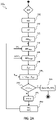
- Figure 2A shows an activity diagram of an offline TOF method 200 A according to embodiments of the present invention.
- the offline TOF method 200 A is implemented by proper software instructions stored in or accessible by the TOF device 100, and/or by proper hardware/firmware of the TOF device 100.
- the offline TOF method 200 A comprises acquiring the ultrasonic echo signal UES thereby obtaining the corresponding electric echo signal EES (action node 205).
- the acquisition of the ultrasonic echo signal UES to obtain the corresponding electric echo signal EES is performed at the conditioning and conversion system (not shown) of the ultrasonic transducer 105.
- the offline TOF method 200 A comprises determining the noise power NP of the electric echo signal EES (action node 210).
- the noise power NP of the electric echo signal EES is determined at the Fourier module 115 of the processing unit 110.
- the offline TOF method 200 A comprises determining the envelope signal EES ENV (action node 215).
- the envelope signal EES ENV is determined at the Hilbert module 120 of the processing unit 110.
- the offline TOF method 200 A comprises determining the envelope signal portion EES ENV,p (action node 220).
- the envelope signal portion EES ENV,p is determined at the portion module 125 of the processing unit 110.
- the envelope signal portion EES ENV,p is determined based on the operative parameters OPk resulting from Particle Swarm Optimization performed at the previous (( k-1)- th) iteration before the current ( k -th) iteration.
- the operative parameters OPk are at default values, the default values being for example determined at manufacturer side, e.g. based on design experience.
- the offline TOF method 200 A comprises determining the envelope signal estimate EES ENV,est according to the envelope signal portion EES ENV,p and the noise power NP (action node 225).
- the envelope signal portion EES ENV,p is determined at the UKF module 130 of the processing unit 110, as better discussed in the following with reference to Figure 4 .
- the envelope signal estimate EES ENV,est is determined based on the UKF parameters UKFP k resulting from Particle Swarm Optimization performed at the previous (( k-1)- th) iteration before the current ( k -th) iteration.
- the UKF parameters UKFPk are at default values, the default values for example being determined at manufacturer side, e.g. based on designer experience.
- the offline TOF method 200 A comprises determining the TOF estimate according to the envelope signal estimate EES ENV,est and the distance estimate D EST according to the TOF estimate (action node 230). According to an embodiment, the TOF estimate and the distance estimate D EST are determined at the evaluation module 135 of the processing unit 110.
- the offline TOF method 200 A comprises determining the estimate error ⁇ as the difference between the distance estimate D EST and the distance D ACT (action node 235 A ).
- the estimate error ⁇ is determined at the error module 140 of the processing unit 110.
- the offline TOF method 200 A comprises iteratively adjusting and refining the operative parameters OPk and the UKF parameters UKFPk (or a subset thereof) as long as the estimate error ⁇ is higher than a threshold estimate error ⁇ TH .
- the estimate error ⁇ is higher than the threshold estimate error ⁇ TH (exit branch N of decision node 240)
- the operative parameters OPk and the UKF parameters UKFPk are adjusted at the Swarm module 145 of the processing unit 110 based on the estimate error ⁇ received as input by the error module 140 and on the Particle Swarm Optimization.
- nodes 220-250 are repeated as such as long as the estimate error ⁇ is higher than the threshold estimate error ⁇ TH .
- the offline TOF method 200 A ends.
- the offline TOF method may be useful in the design phase, in which the TOF estimate is determined with great accuracy from a set of signals in a supervised manner and with known measurement conditions.
- the Applicant has experimentally ascertained that a TOF device with operative and UKF parameters optimized through the offline TOF method is capable of managing a very large number of shapes of ultrasonic echo signals for distances within 0.30 m to 2 m, with a mean accuracy lower than 3mm.
- Figure 2B shows an activity diagram of an online TOF method 200 B according to embodiments of the present invention.
- the online TOF method 200 B is implemented by proper software instructions stored in or accessible by the TOF device 100, and/or by proper hardware/firmware of the TOF device 100.
- the online TOF method 200 B comprises acquiring the ultrasonic echo signal UES thereby obtaining the corresponding electric echo signal EES (action node 205).
- the acquisition of the ultrasonic echo signal UES to obtain the corresponding electric echo signal EES is performed at the conditioning and conversion system (not shown) of the ultrasonic transducer 105.
- the online TOF method 200 B comprises determining the noise power NP of the electric echo signal EES (action node 210). According to an embodiment, the noise power NP of the electric echo signal EES is determined at the Fourier module 115 of the processing unit 110.
- the online TOF method 200 B comprises determining the envelope signal EES ENV (action node 215).
- the envelope signal EES ENV is determined at the Hilbert module 120 of the processing unit 110.
- the online TOF method 200 B comprises determining the envelope signal portion EES ENV,p (action node 220).
- the envelope signal portion EES ENV,p is determined at the portion module 125 of the processing unit 110.
- the envelope signal portion EES ENV,p is determined based on the subset of the operative parameters OPk resulting from Particle Swarm Optimization performed at the previous (( k - 1 )-th) iteration before the current ( k -th) iteration.
- the subset of the operative parameters OPk are at default values, the default values being for example determined at manufacturer side, e.g. based on designer experience, or at an offline TOF method (such as the offline TOF method 200 A ) performed before the online TOF method 200 B .
- the subset of the operative parameters OPk comprise, but are not limited to, the third and fourth operative parameters Coeff1, Coeff2 (i.e., the operative parameters indicative of optimized lengths of the left and right portions of the envelope signal EES ENV , and hence of an optimized overall length of the envelope signal portion EES ENV,p over the abscissae axis).
- the Applicant has experimentally ascertained that the first and second operative parameters Perc_l, Perc_u, especially when they are tuned during an offline TOF method (such as the offline TOF method 200 A ) preceding the online TOF method 200 B , are valid enough to allow identifying (together with the third and fourth operative parameters Coeff1, Coeff2 tuned during the online method 200 B ) the best envelope signal portion EES ENV,p .
- the online TOF method 200 B comprises determining the envelope signal estimate EES ENV,est according to the envelope signal portion EES ENV,p and the noise power NP (action node 225).
- the envelope signal portion EES ENV,p is determined at the UKF module 130 of the processing unit 110, as better discussed in the following with reference to Figure 4 .
- the envelope signal estimate EES ENV,est is determined based on the subset of the UKF parameters UKFPk resulting from Particle Swarm Optimization performed at the previous (( k-1)- th) iteration before the current ( k -th) iteration.
- the subset of the UKF parameters UKFPk are at default values, the default values being for example determined at manufacturer side, e.g. based on designer experience.
- the subset of the UKF parameters UKFPk comprise, but are not limited to, the evaluation parameter and the control parameter.
- the Applicant has experimentally ascertained that some parameters, such as the correction parameter, do not affect (or do not substantially affect) the TOF estimate. Therefore, according to an embodiment, the correction parameter, especially when it is tuned during an offline TOF method (such as the offline TOF method 200 A ) preceding the online TOF method 200 B , is not tuned again during the online TOF method 200 B .
- the online TOF method 200 B comprises determining the estimate error ⁇ as the difference between the envelope signal estimate EES ENV,est and the envelope signal EES ENV (action node 235 B ).
- the estimate error ⁇ is determined at the error module 140 of the processing unit 110.
- the online TOF method 200 B comprises iteratively adjusting and refining the subset of the operative parameters OPk and the subset of the UKF parameters UKFP k as long as the estimate error ⁇ is higher than a threshold estimate error ⁇ TH .
- the estimate error ⁇ is higher than the threshold estimate error ⁇ TH (exit branch N of decision node 240)
- the subset of the operative parameters OPk and the subset of the UKF parameters UKFPk are adjusted at the Swarm module 145 of the processing unit 110 based on the estimate error ⁇ received as input by the error module 140 and on the Particle Swarm Optimization.
- nodes 220-250 are repeated as such as long as the estimate error ⁇ is higher than the threshold estimate error ⁇ TH .
- the TOF estimate is determined according to the envelope signal estimate EES ENV,est (i.e., the envelope signal estimate EES ENV,est determined based on the optimized subset of the operative parameters OPk and the optimized subset of the UKF parameters UKFP k ) and the distance estimate D EST is determined according to the TOF estimate (action node 230).
- the TOF estimate and the distance estimate D EST are determined at the evaluation module 135 of the processing unit 110.
- the optimized subset of the operative parameters OPk and the optimized subset of the UKF parameters UKFPk are properly stored (action node 255) to be used for the following running of the online TOF method 200 B .
- the online TOF method provides a TOF estimate that dynamically and automatically adapts to different external conditions.
- the offline TOF method 200 A and the online TOF method 200 B are carried out on a training dataset comprising, for example, 160 ultrasonic echo signals (e.g., 135 used for the offline tuning and 25 used for testing the online tuning) indicative of distances between the target object T and the TOF device 100 ranging between about 0.3m and about 2m and acquired at a sampling rate of about 400kS/s.
- 160 ultrasonic echo signals e.g., 135 used for the offline tuning and 25 used for testing the online tuning
- the 25 ultrasonic echo signals used for testing the online tuning are acquired under various operative conditions (e.g., variable temperature, humidity, wind speed, etc.).
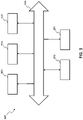
- FIG. 3 shows a simplified block diagram of an electronic system 300 (i.e., a portion thereof) comprising the TOF device 100 (or more thereof) according to an embodiment of the present invention.
- the electronic system 300 is suitable for use in electronic apparatus.
- the electronic system 300 comprises a controller 305 (for example, one or more microprocessors and/or one or more microcontrollers).
- a controller 305 for example, one or more microprocessors and/or one or more microcontrollers.
- the electronic system 300 comprises an input/output device 310 (for example, a keyboard and/or a screen).
- the input/output device 310 may for example be used to generate and/or receive messages.
- the input/output device 310 may for example be configured to receive/supply a digital signal and/or an analog signal.
- the electronic system 300 comprises a wireless interface 315 for exchanging messages with a wireless communication network (not shown), for example by means of radio frequency signals.
- a wireless interface may include antennas and wireless transceivers.
- the electronic system 300 comprises a power supply device (for example, a battery 320) for powering the electronic system 300.
- a power supply device for example, a battery 320
- the controller 305 may be configured to determine additional information (such as displacement information, level information, material information, structure information, vibration information, and medical diagnostic information) based on the distance information provided by the TOF device 100.
- additional information such as displacement information, level information, material information, structure information, vibration information, and medical diagnostic information
- the electronic system 300 comprises one more communication channels (bus) 325 to allow the exchange of data between the TOF device 100, the controller 305 (when provided), the input/output device 310 (when provided), the wireless interface 315 (when provided), and the power supply device 320 (when provided).
- bus communication channels
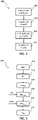
- Figure 4 shows an activity diagram of a signal cutting method 400 according to embodiments of the present invention.
- the signal cutting method 400 allows, during use of the TOF device 100, to determine the envelope signal portion EES ENV,p by applying the operative parameters to the envelope signal EES ENV .
- the signal cutting method 400 is implemented by proper software instructions stored in or accessible by the TOF device 100, and/or by proper hardware/firmware of the TOF device 100.
- the signal cutting method 400 is implemented by the portion module 125.
- the signal cutting method 400 comprises determining the maximum of the envelope signal EES ENV (action node 405) according to per se known techniques, i.e. comprises calculating a maximum value max_inv of the envelope signal EES ENV and a first temporal position x_max_inv (over the abscissae axis, i.e. over time; also called first time instant x_max_inv) in the envelope signal EES ENV of said maximum value max_inv.
- the signal cutting method 400 comprises calculating, through the first and the second operative parameter Perc_l, Perc_u, respectively a first threshold value thresh1 and a second threshold value thresh2 of the envelope signal EES ENV (action node 410), which are lower than the maximum value max_inv.
- the first threshold value thresh1 is a threshold for the envelope signal EES ENV that is related to a maximum length of the left portion of the envelope signal EES ENV
- the second threshold value thresh2 is a threshold for the envelope signal EES ENV that is related to a maximum length of the right portion of the envelope signal EES ENV .
- the left portion of the envelope signal EES ENV comprises values of the envelope signal EES ENV ranging between the first threshold value thresh1 and the maximum value max_inv
- the right portion of the envelope signal EES ENV comprises values of the envelope signal EES ENV ranging between the maximum value max_inv and the second threshold value thresh2.
- the first threshold value thresh1 and the second threshold value thresh2 are calculated based on (in particular, dependent on the product of) the maximum value max_inv of the envelope signal EES ENV and the first and, respectively, the second operative parameter Perc_l, Perc_u.
- thresh1 Perc_l ⁇ max_inv
- thresh2 Perc_u ⁇ max_inv.
- the signal cutting method 400 further comprises determining a second temporal position x_thresh1 (over the abscissae axis, i.e. over time; also called second time instant x_max_inv) of the first threshold value thresh1 and a third temporal position x_thresh2 (over the abscissae axis, i.e.
- third time instant x_max_inv of the second threshold value thresh2 in the envelope signal EES ENV (action node 415), the second and third temporal position x_thresh1, x_thresh2 being related to a maximum length of the left and, respectively, right portion of the envelope signal EES ENV .
- the first and second temporal positions x_thresh1, x_thresh2 are the temporal positions of the envelope signal EES ENV at which the envelope signal EES ENV assumes the first and, respectively, the second threshold values thresh1, thresh2 and are positioned prior to and, respectively, following the first temporal position x_max_inv (i.e., are at left and, respectively, at right of the first temporal position x_max_inv on the time scale).
- the envelope signal portion EES ENV,p includes (in details, coincides with) the portion of the envelope signal EES ENV comprised between the second temporal position x_thresh1 and the third temporal position x_thresh2.
- the signal cutting method 400 further comprises optimizing the envelope signal portion EES ENV,p by calculating, through the third and fourth operative parameters Coeff1, Coeff2, a fourth temporal position x_opt1 (over the abscissae axis, i.e. over time; also called fourth time instant x_max_inv) and a fifth temporal position x_opt2 (over the abscissae axis, i.e. over time; also called fifth time instant x_max_inv) of the envelope signal EES ENV (action node 420).
- the fourth temporal position x_opt1 is greater than the second temporal position x_thresh1 and depends on the second temporal position x_thresh1 and the third operative parameter Coeff1
- the fifth temporal position x_opt2 is lower than the third temporal position x_thresh2 and depends on the third temporal position x_thresh2 and the fourth operative parameter Coeff2.
- the envelope signal portion EES ENV,p includes (in details, coincides with) the portion of the envelope signal EES ENV comprised between the fourth temporal position x_opt1 and the fifth temporal position x_opt2.
- the fourth temporal position x_opt1 and the fifth temporal position x_opt2 are indicative of an optimized length of the left and, respectively, of the right portion of the envelope signal EES ENV .
- the third and fourth operative parameters Coeff1, Coeff2 are indicative of respective time offsets to be applied respectively to the second and third temporal positions x_thresh1, x_thresh2 to obtain the fourth and fifth temporal position x_opt1, x_opt2.
- FIG. 5 shows an activity diagram of a time-of-flight estimation method 500 according to embodiments of the present invention.
- the time-of-flight estimation method 500 allows to estimate the time-of-flight between the ultrasonic signal emitted by the TOF device 100 and the ultrasonic echo signal returned by the target object T hit by the ultrasonic signal and received at the TOF device 100.
- the time-of-flight estimation method 500 is implemented by proper software instructions stored in or accessible by the TOF device 100, and/or by proper hardware/firmware of the TOF device 100.
- the time-of-flight estimation method 500 comprises acquiring the ultrasonic echo signal UES thereby obtaining the corresponding electric echo signal EES (action node 505).
- the acquisition of the ultrasonic echo signal UES to obtain the corresponding electric echo signal EES is performed at the conditioning and conversion system (not shown) of the ultrasonic transducer 105.
- the time-of-flight estimation method 500 comprises determining the noise power NP of the electric echo signal EES (action node 510). According to an embodiment, the noise power NP of the electric echo signal EES is determined at the Fourier module 115 of the processing unit 110.
- the time-of-flight estimation method 500 comprises determining the envelope signal EES ENV (action node 515). According to an embodiment, the envelope signal EES ENV is determined at the Hilbert module 120 of the processing unit 110.
- the time-of-flight estimation method 500 comprises determining the envelope signal portion EES ENV,p (action node 400) according to the previously described signal cutting method 400.
- the envelope signal portion EES ENV,p is determined at the portion module 125 of the processing unit 110 based on the operative parameters OPk resulting from the offline TOF method 200 A or the online TOF method 200 B .
- the time-of-flight estimation method 500 comprises determining the envelope signal estimate EES ENV,est according to the envelope signal portion EES ENV,p and the noise power NP (action node 525).
- the envelope signal portion EES ENV,p is determined at the UKF module 130 of the processing unit 110 based on the UKF parameters UKFP k resulting from the offline TOF method 200 A or the online TOF method 200 B .
- the time-of-flight estimation method 500 comprises determining the TOF estimate according to the envelope signal estimate EES ENV,est and the distance estimate D EST according to the TOF estimate (action node 530). According to an embodiment, the TOF estimate and the distance estimate D EST are determined at the evaluation module 135 of the processing unit 110.
- the signal cutting method 400 reduces the computational cost required for estimating the time-of-flight through the time-of-flight estimation method 500, in particular by reducing the computation cost of the UKF module 130.
- the envelope signal portion EES ENV,p outputted by the action node 415 is already optimized for the UKF module 130. Nevertheless, calculating the envelope signal portion EES ENV,p according to the action node 420 allows to further reduce the computational cost and improve the time-of-flight estimation accuracy.
- the optimized subset of the operative parameters OPk and the optimized subset of the UKF parameters UKFPk are calculated through the offline TOF method 200 A .
- the third and fourth operative parameters Coeff1, Coeff2 can be further optimized through the online TOF method 200 B .
Landscapes
- Engineering & Computer Science (AREA)
- Physics & Mathematics (AREA)
- General Physics & Mathematics (AREA)
- Radar, Positioning & Navigation (AREA)
- Remote Sensing (AREA)
- Computer Networks & Wireless Communication (AREA)
- Mathematical Physics (AREA)
- Acoustics & Sound (AREA)
- Data Mining & Analysis (AREA)
- Mathematical Optimization (AREA)
- Mathematical Analysis (AREA)
- Pure & Applied Mathematics (AREA)
- Computational Mathematics (AREA)
- Theoretical Computer Science (AREA)
- Algebra (AREA)
- Databases & Information Systems (AREA)
- Software Systems (AREA)
- General Engineering & Computer Science (AREA)
- Measurement Of Velocity Or Position Using Acoustic Or Ultrasonic Waves (AREA)
- Radar Systems Or Details Thereof (AREA)
Abstract
Description
- The present invention relates to a device for ultrasonic time-of-flight (TOF) estimate (hereinafter, TOF device) and a corresponding method implemented by the TOF device.
- According to ultrasonic TOF estimate principles, an ultrasonic signal (hereinafter, ultrasonic source signal) is generated and transmitted by the TOF device towards a target body, a corresponding ultrasonic signal (hereinafter, ultrasonic echo signal) originated from the target body by reflection of the ultrasonic source signal hitting the target body is received at the TOF device, and the TOF estimate is determined as the time elapsed from the transmission of the ultrasonic source signal and the reception of the ultrasonic echo signal.
- In typical applications, e.g. in applications for obstacle detection, the TOF device may be configured to determine, e.g. based on the TOF estimate, a distance estimate indicative of a distance between the TOF device and the target body.
- The output of the TOF device may be the distance estimate, and/or the distance estimate may be part of an additional information based on the distance estimate, such as displacement information, level information, material information, structure information, vibration information, and medical diagnostic information.
- According to a known implementation, the TOF estimate is based on Kalman Filter, which is an algorithm that, given a set of measures, generates an optimal estimate of desired quantities through a recursive processing.
- Extended Kalman Filter is also known, which applies to non-linear systems. Basically, the Extended Kalman Filter provides for a linearization of a non-linear system through Jacobian computation.
- Unscented Kalman Filter is also known, which also applies to non-linear systems. Basically, the Unscented Kalman Filter provides for a linearization of probabilistic distributions of an error.
- Nowadays, TOF estimate based on the Unscented Kalman Filter is a preferred choice.
- Article "Ultrasonic time-of-flight estimation through unscented Kalman filter", Angrisani et al., The institution of Electrical Engineers, Stevenage, GB relates to distance or level measurements based on ultrasonic time-of-flight estimation, through unscented Kalman filter.
- Document
US 2014/204700 relates to methods and devices for automatically characterizing one or more echoes contained in an ultrasonic signal. - The Applicant has understood that TOF estimate based on the Unscented Kalman Filter has some drawbacks.
- Particularly, the Applicant has understood that the performances of the Unscented Kalman Filter are closely related to an efficient calibration of a large number of parameters (including parameters associated with an acquisition of the ultrasonic echo signal and parameters of the Unscented Kalman Filter).
- Due to the large number of parameters to be calibrated and since the calibration of these parameters is almost always done by hand according to designer experience, the performances of the Unscented Kalman Filter may often be below expectations.
- Moreover, the Applicant has also understood that, during TOF device lifetime, the TOF estimates may also be affected by external conditions (such as environmental conditions). Particularly, changes in air temperature, humidity, air pressure, air turbulence, external noise may heavily affect an ultrasonic signal acquisition, so that parameter calibration could result inadequate as a result of changed external conditions.
- Last but not least, the Applicant has understood that high computational complexity of current TOF estimate methods does not allow efficient implementation in available microcontrollers.
- The Applicant has faced the above-mentioned issues, and has devised a method for TOF estimate and a corresponding TOF device that allows easily and dynamically tuning (i.e., adjusting or updating or refining or calibrating) the parameters associated with the processing of the acquired ultrasonic echo signal and the parameters of the Unscented Kalman Filter.
- One or more aspects of the present invention are set out in the independent claims, with advantageous features of the same invention that are indicated in the dependent claims, whose wording is enclosed herein verbatim by reference (with any advantageous feature being provided with reference to a specific aspect of the present invention that applies mutatis mutandis to any other aspect).
- More specifically, an aspect of the present invention relates to a method for providing an estimate of a time-of-flight between an ultrasonic signal emitted by a device and an ultrasonic echo signal returned by a target object hit by the ultrasonic signal and received at the device. The method may comprise acquiring the ultrasonic echo signal thereby obtaining an electric echo signal. The method may comprise determining a noise power of the electric echo signal. The method may comprise determining an envelope signal indicative of an envelope of the electric echo signal. The method may comprise determining a portion of the envelope signal based on at least one operative parameter; said at least one operative parameter may be determined according to Particle Swarm Optimization. The method may comprise processing the portion of the envelope signal and the noise power of the echo ultrasonic signal according to an Unscented Kalman Filter to obtain an estimate of the envelope signal; the estimate of the envelope signal may be a regenerated version of the envelope signal being regenerated from the portion of the envelope signal; said processing may for example be based on at least one Unscented Kalman Filter parameter (UKFPK ) determined according to the Particle Swarm Optimization. The method may comprise providing said estimate of the time-of-flight according to the estimate of the envelope signal.
- According to an embodiment, whose features are additional or alternative to one or more features of any of the previous embodiments, the method comprises determining an estimate error. The Particle Swarm Optimization may be based on said estimate error.
- According to an embodiment, whose features are additional or alternative to one or more features of any of the previous embodiments said determining an estimate error comprises determining a difference between the estimate of envelope signal and the envelope signal.
- According to an embodiment, whose features are additional or alternative to one or more features of any of the previous embodiments, the method comprises, based on said estimate of the time-of-flight, determining a distance estimate indicative of a distance between the target object and the device. Said determining an estimate error may comprise determining a difference between the distance estimate and said distance.
- According to an embodiment, whose features are additional or alternative to one or more features of any of the previous embodiments, said determining an envelope signal comprises performing a Hilbert transformation on the echo ultrasonic signal.
- According to an embodiment, whose features are additional or alternative to one or more features of any of the previous embodiments, the portion of the envelope signal is centered about a maximum value of the envelope signal.
- According to an embodiment, whose features are additional or alternative to one or more features of any of the previous embodiments, said processing the operative portion of the envelope signal comprises providing a regenerated envelope signal.
- According to an embodiment, whose features are additional or alternative to one or more features of any of the previous embodiments, said at least one operative parameter comprises at least one among:
- operative parameters indicative of a maximum length of the portion of the envelope signal over time, and
- operative parameters indicative of an optimized length of the portion of the envelope signal over time, the optimized length being lower than the maximum length.
- According to an embodiment, whose features are additional or alternative to one or more features of any of the previous embodiments, said at least one Unscented Kalman Filter parameter comprises at least one among:
- an evaluation parameter providing a rough estimate of the time-of-flight;
- a control parameter for controlling the spread of sigma points around a mean state value, and
- a correction parameter providing a correction on the noise power of the electric echo signal.
- Another aspect of the present invention relates to a device for providing an estimate of a time-of-flight between an ultrasonic signal emitted by the device and an ultrasonic echo signal returned by a target object hit by the ultrasonic signal and received at the device. The device may comprise a conditioning and conversion system for acquiring the ultrasonic echo signal thereby obtaining an electric echo signal. The device may comprise a module for determining a noise power of the electric echo signal. The device may comprise a module for determining an envelope signal indicative of an envelope of the electric echo signal. The device may comprise a module for determining a portion of the envelope signal based on at least one operative parameter; said at least one operative parameter may be determined according to Particle Swarm Optimization. The device may comprise a module for processing the portion of the envelope signal and the noise power of the echo ultrasonic signal according to an Unscented Kalman Filter to obtain an estimate of the envelope signal; the estimate of the envelope signal may be a regenerated version of the envelope signal being regenerated from the portion of the envelope signal; said processing may be based on at least one Unscented Kalman Filter parameter determined according to the Particle Swarm Optimization. The device may comprise a module for providing said estimate of the time-of-flight according to the estimate of the envelope signal.
- A further aspect of the present invention relates to an electronic system comprising such a device (or more thereof).
- These and other features and advantages of the present invention will be made apparent by the following description of some exemplary and non-limitative embodiments thereof; for its better intelligibility, the following description should be read making reference to the attached drawings, wherein:
-
Figure 1 schematically shows a device for ultrasonic time-of-flight estimate, according to an embodiment of the present invention; -
Figures 2A and2B show activity diagrams of methods according to respective embodiments of the present invention; -
Figure 3 shows a simplified block diagram of an electronic system comprising the device ofFigure 1 according to an embodiment of the present invention; and -
Figures 4 and 5 show activity diagrams of respective methods according to respective embodiments of the present invention. - With reference to the drawings,
Figure 1 schematically shows a device (hereinafter, TOF device) 100 for providing an ultrasonic time-of-flight estimate (hereinafter, TOF estimate), according to an embodiment of the present invention. TheTOF device 100 is configured to implement a method (hereinafter, TOF method) for providing the TOF estimate. - In the following, when one or more features of the TOF device and of the TOF method are introduced by the wording "according to an embodiment", they are to be construed as features additional or alternative to any features previously introduced, unless otherwise indicated and/or unless there is evident incompatibility among feature combinations.
- In the following, only components of (and TOF method steps performed by) the
TOF device 100 deemed relevant for the understanding of the present invention will be shown and discussed, with other well-known components of (and TOF method steps performed by) theTOF device 100 that will be intentionally omitted for the sake of conciseness. - According to ultrasonic time-of-flight estimate principles, an ultrasonic signal (hereinafter, ultrasonic source signal) USS is generated and transmitted by the
TOF device 100 towards a target body T (the target body being eternal to, i.e. not part of, the TOF device 100), a corresponding ultrasonic signal (hereinafter, ultrasonic echo signal) UES originated from the target body T by reflection of the ultrasonic source signal USS hitting the target body T is received at theTOF device 100, and the TOF estimate is determined (by the TOF device 100) as the time elapsed from the transmission of the ultrasonic source signal USS and the reception of the ultrasonic echo signal UES. - According to an embodiment, the
TOF device 100 is configured to determine, e.g. based on the TOF estimate, a distance estimate DEST indicative of a distance DACT between theTOF device 100 and the target body T. - According to an embodiment, the
TOF device 100 may be configured to further determine, e.g. based on the TOF estimate and/or on the distance estimate DEST, one or more additional information. According to an embodiment, as better discussed in the following, theTOF device 100 may be part of an electronic system aimed at determining the additional information based on the TOF estimate and/or on the distance estimate DEST provided by theTOF device 100. - Examples of additional information include, but are not limited to, displacement information, level information, material information, structure information, vibration information, and medical diagnostic information.
- For the purposes of the present disclosure, the target body T (which is not part of the TOF device 100) comprises a physical object with mass. Examples of target bodies include, but are not limited to, living beings (such as persons, animals and trees) or parts thereof, and inanimate objects (such as buildings and vehicles) or parts thereof.
- According to an embodiment, the
TOF device 100 comprises anultrasonic transducer 105. According to an embodiment, theultrasonic transducer 105 comprises a piezoelectric ultrasonic transducer or a capacitive ultrasonic transducer. - According to an embodiment, the
ultrasonic transducer 105 is configured to transduce an electric source signal ESS (e.g., a pulse-width modulated pulse train) into the ultrasonic source signal USS, and to transduce the ultrasonic echo signal UES from the target body T to obtain a corresponding electric echo signal EES. - According to an embodiment, the electric source signal ESS and the electric echo signal EES are digital signals, the
ultrasonic transducer 105 for example comprising a conditioning and conversion system (not shown) for obtaining (from the (digital) electric source signal ESS) an analog ultrasonic source signal to be transduced into the electric echo signal EES, and for obtaining the (digital) electric echo signal EES from the transduced ultrasonic echo signal. - According to an embodiment, the
TOF device 100 comprises a processing unit 110 (for example, a microcontroller and/or a microprocessor) electrically coupled to theultrasonic transducer 105 for providing the electric source signal ESS thereto and for receiving the electric echo signal EES therefrom. - In the following, only relevant modules of the
processing unit 110 that are deemed pertinent for the understanding of the present invention will be discussed, with well-known and/or obvious variants of the relevant modules that are omitted for the sake of conciseness. - The term "module" is herein intended to emphasize functional (rather than implementation) aspects thereof. Indeed, without losing generality, each module, according to its function, may be implemented by software, hardware, and/or a combination thereof. Moreover, the modules (or at least a subset thereof) may also reflect, at least conceptually, the physical structure of the processing unit. In any case, it will be appreciated that one or more of the illustrated modules may be integrated together in a single electronic unit.
- According to an embodiment, the
processing unit 110 comprises amodule 115 for determining a noise power NP (or an indication thereof) associated with the electric echo signal EES. - According to an embodiment, in order to determine the noise power NP (or an indication thereof) associated with the electric echo signal EES, the
module 115 is configured to process the electric echo signal EES according to Fourier transform (reason why, in the following, themodule 115 will be referred to as Fourier module 115). - According to an embodiment, the
processing unit 110 comprises amodule 120 for determining an envelope signal EESENV indicative of an envelope (e.g., a profile) of the echo ultrasonic signal. - According to an embodiment, in order to determine the envelope signal EESENV, the
module 120 is configured to process the electric echo signal EES according to Hilbert transform (reason why, in the following, themodule 120 will be referred to as Hilbert module 120). - Since the frequency of the envelope signal EESENV is lower than the frequency of the electric echo signal EES, the envelope signal EESENV can be appropriately decimated in terms of sample/s without violating Nyquist requests. Thus, the
Hilbert module 120 performs a first signal "dilution" without loss of information content, which determines low computational requests for theprocessing unit 110. Just as an example, the frequency of the electric echo signal EES may be about 400KHz and the frequency of the envelope signal EESENV may be about 25KHz. - According to an embodiment, the
processing unit 110 comprises amodule 125 for determining a portion of the envelope signal EESENV (reason why, in the following, themodule 125 will be referred to asportion module 125 and the portion of the envelope signal EESENV will be referred to as envelope signal portion EESENV,p ). - According to an embodiment, the envelope signal portion EESENV,p comprises a portion of the envelope signal EESENV comprising a maximum value of the envelope signal EESENV , i.e. comprises a portion of the envelope signal EESENV at the left of the maximum value (hereinafter, left portion of the envelope signal EESENV ) and a portion of the envelope signal EESENV at the right of the maximum value (hereinafter, right portion of the envelope signal EESENV ). The left portion of the envelope signal EESENV and the right portion of the envelope signal EESENV may have same time lengths (i.e., said portion of the envelope signal EESENV is centered around said maximum value of the envelope signal EESENV ) or may have different time lengths (i.e., said portion of the envelope signal EESENV is not centered around said maximum value of the envelope signal EESENV ).
- As the envelope signal portion EESENV,p is a portion of the envelope signal EESENV, the envelope signal portion EESENV,p can be quickly processed by the following modules of the processing unit 110 (so as to obtain a fast TOF estimate, and hence a fast distance estimate DEST ). Thus, the
portion module 125 performs a second signal "dilution" without loss of information content, which determines low computational requests for theprocessing unit 110. - Thanks to the low computational requests for the
processing unit 110, theprocessing unit 110 may be a conventional microcontroller available on the market. - According to an embodiment, the envelope signal portion EESENV,p is determined based on one or more operative parameters.
- Examples of operative parameters comprise, but are not limited to:
- a first operative parameter Perc_l indicative of a maximum length of the left portion of the envelope signal EESENV. In other words, the first operative parameter Perc_l is indicative of an admitted extent of the left portion of the envelope signal EESENV over the abscissae axis (i.e., over time), and may for example depend on processing capabilities of the following modules of the
processing unit 110 and/or on other design options; - a second operative parameter Perc_u indicative of a maximum length of the right portion of the envelope signal EESENV. In other words, the second operative parameter Perc_u is indicative of an admitted extent of the right portion of the envelope signal EESENV over the abscissae axis (i.e., over time), and may for example depend on processing capabilities of the following modules of the
processing unit 110 and/or on other design options (therefore, the first and second operative parameters are indicative of a maximum length of the envelope signal portion EESENV,p over time); - a third operative parameter Coeff1 (optional) indicative of an optimized length of the left portion of the envelope signal EESENV. In other words, the third operative parameter Coeff1 is indicative of an optimized extent (lower than the admitted extent) of the left portion of the envelope signal EESENV over the abscissae axis (i.e., over time). Compared to the admitted extent, the optimized length of the left portion of the envelope signal EESENV can further reduce the computation requested by the following modules of the
processing unit 110 without losing information content; - a fourth operative parameter Coeff2 (optional) indicative of an optimized length of the right portion of the envelope signal EESENV. In other words, the fourth operative parameter Coeff2 is indicative of an optimized extent (lower than the admitted extent) of the right portion of the envelope signal EESENV over the abscissae axis (therefore, the third and fourth operative parameters Coeff1, Coeff2 are indicative of an optimized length of the envelope signal portion EESENV,p over time). Compared to the admitted extent, the optimized length of the right portion of the envelope signal EESENV can further reduce the computation requested by the following modules of the
processing unit 110 without losing information content. - In the following, when distinguishing among the first, second, third and fourth operative parameters is not relevant for understanding the invention the operative parameters will be globally denoted by OPk, wherein k denotes the iteration of the TOF method - indeed, as better discussed in the following, according to an embodiment the operative parameters, or at least a subset thereof, are tuned or adjusted or updated at each iteration of the TOF method.
- According to an embodiment, the operative parameters, or a subset thereof, are determined according to Particle Swarm Optimization (as better discussed in the following).
- According to an embodiment, the
portion module 125, better discussed in the following, is configured to determine the envelope signal portion EESENV,p by applying to the envelope signal EESENV the first and second operative parameters Perc_l, Perc_u at a first phase, and the third and fourth operative parameters Coeff1, Coeff2 at a second phase (following the first phase) aimed at optimizing the length of the envelope signal portion EESENV,p. - According to an embodiment, the
processing unit 110 comprises amodule 130 for processing the envelope signal portion EESENV,p and the noise power NP of the electric echo signal EES according to an Unscented Kalman Filter (reason why, in the following, themodule 130 will be referred to as UKF ("Unscented Kalman Filter") module 130). - Kalman filter is an algorithm that uses a series of measurements observed over time, containing statistical noise and other inaccuracies, and produces estimates of unknown variables that tend to be more accurate than those based on a single measurement alone, by estimating a joint probability distribution over the variables for each timeframe.
- The Kalman filter keeps track of the estimated state of the system and the variance or uncertainty of the estimate. The estimate is updated using a state transition model and measurements.
- The algorithm works in a two-step process. In a prediction step, the Kalman filter produces estimates of the current state variables, along with their uncertainties. Once the outcome of the next measurement (necessarily corrupted with some amount of error, including random noise) is observed, these estimates are updated using a weighted average, with more weight being given to estimates with higher certainty. The algorithm is recursive. It can run in real time, using only the present input measurements and the previously calculated state and its uncertainty matrix; no additional past information is required.
- Unscented Kalman filter is a generalization of the Kalman filter which works on nonlinear systems. In the UKF, the probability density is approximated by a deterministic sampling of points which represent the underlying distribution as a Gaussian. The nonlinear transformation (referred to as unscented transformation) of these points are intended to be an estimate of the posterior distribution, the moments of which can then be derived from the transformed samples.
- According to an embodiment, the
UKF module 130 is configured to process the envelope signal portion EESENV,p and the noise power NP of the echo ultrasonic signal based on one or more UKF parameters (the UKF parameters, or a subset thereof, being determined according to the Particle Swarm Optimization, as better discussed in the following). - Examples of UKF parameters comprise, but are not limited to an evaluation parameter ("to_md_capture") providing a first, rough evaluation of the TOF estimate (so as to provide a good starting point to the UKF module 130), a control parameter ("Kappa_p") for controlling the spread of the sigma points around the mean state value, and a correction parameter ("powerNoiseCorr") providing a correction on the noise power NP (the correction parameter being for example an additive correction factor to be added to the noise covariance matrix associated with the electric echo signal EES). In other words, the "to_md_capture" parameter is indicative of an approximate estimation of the time-of-flight used as a starting point for the time-of-flight calculation and is proportional to x_max_inv - 3σ, the x_max_inv being described in the following and the σ being a predefined value linked to the standard deviation of a Gaussian curve approximating the envelope signal portion EESENV,p, and the "Kappa_p" parameter is indicative of the spread of the sigma points around a mean value of the state variable of the UKF.
- In the following, the UKF parameters will be globally denoted by UKFPk, wherein k denotes the iteration of the TOF method (indeed, as better discussed in the following, according to an embodiment the UKF parameters are tuned or adjusted or updated at each iteration of the TOF method).
- According to an embodiment, the
UKF module 130 is configured to process the envelope signal portion EESENV,p and the noise power NP of the electric echo signal EES to obtain an estimate of the envelope signal EESENV (hereinafter referred to as envelope signal estimate EESENV,est ). According to an embodiment, the envelope signal estimate EESENV,est is a regenerated version of the envelope signal EESENV being regenerated from the envelope signal portion EESENV,p (see, for example, L. Angrisani, A. Baccigalupi, R. Schiano Lo Moriello, "Ultrasonic time-of-flight estimation through unscented Kalman filter", IEEE Transactions on Instrumentation and Measurement, Aug. 2006). - According to an embodiment, the
processing unit 110 comprises a module (hereinafter, evaluation module) 135 for determining the TOF estimate according to the envelope signal estimate EESENV,est. - According to an embodiment, the TOF estimate is based on the following discrete-time expression modelling the ultrasonic signal envelope (see, for example, L. Angrisani, A. Baccigalupi, R. Schiano Lo Moriello, "Ultrasonic time-of-flight estimation through unscented Kalman filter", IEEE Transactions on Instrumentation and Measurement, Aug. 2006):

- Ao is the amplitude of the electric echo signal EES;
- α and T are parameters depending on the adopted ultrasonic transducer;
- τ is the TOF estimate, and
- ts is the sampling period.
- According to an embodiment, the
evaluation module 135 is configured to determine, according to the TOF estimate, the distance estimate DEST between the target object T and theTOF device 100. - According to an embodiment, the
processing unit 110 comprises a module (hereinafter, error module) 140 for determining an estimate error ε. As better discussed in the following, the operative parameters OPk (or a subset thereof) and the UKF parameters UKFPk (or a subset thereof) are determined according to the Particle Swarm Optimization receiving the estimate error ε as input). - According to an embodiment, the estimate error ε determined at the
error module 140 comprises a difference between the distance estimate DEST and the distance DACT (i.e., the actual distance) between theTOF device 100 and the target body T. As will be better understood from the following discussion, this embodiment allows iteratively adjusting, tuning, updating or refining the operative parameters OPk (or a subset thereof) and the UKF parameters UKFPk at a preliminary or calibrating phase of the TOF device 100 (i.e., a phase that precedes the use of theTOF device 100 as a meter, e.g. as a distance meter). As better discussed in the following, this preliminary or calibrating phase of theTOF device 100 is obtained through an embodiment of the TOF method (hereinafter referred to as "offline TOF method"), in which a known target body T placed at a known distance DACT is used to set the operative parameters OPk and the UKF parameters UKFPk to be subsequently used by theTOF device 100 when used as a meter (e.g., a distance meter). - According to an embodiment, the estimate error ε determined at the
error module 140 comprises a difference between the envelope signal estimate EESENV,est and the envelope signal EESENV. As will be better understood from the following discussion, this embodiment allows iteratively adjusting, tuning, updating or refining a subset of the operative parameters OPk and a subset of the UKF parameters UKFPk in real-time during the use of theTOF device 100 as a meter (e.g. as a distance meter). As better discussed in the following, this is obtained through an embodiment of the TOF method (hereinafter referred to as "online TOF method"). - According to an embodiment, the
TOF device 100 may be configured to implement the offline TOF method (in which case the distance estimate DEST and the distance DACT are received at the error module 140), or the online TOF method (in which case the envelope signal EESENV and the envelope signal estimate EESENV,est are received at the error module 140), or both the offline and online TOF methods (for example, with the online TOF method that may follow the offline TOF method): the possibility of implementing the offline TOF method and/or the online TOF method is conceptually represented inFigure 1 by dashed arrows associated the distance estimate DEST, the distance DACT, the envelope signal EESENV and the envelope signal estimate EESENV,est being input to theerror module 140. - According to an embodiment, the
processing unit 110 comprises a module (hereinafter, Swarm module) 145 for determining the operative parameters OPk (or the subset of operative parameters OPk ) and the UKF parameters UKFPk (or the subset of UKF parameters UKFPk ) according to the Particle Swarm Optimization and based on the estimate error ε received as input by theerror module 140. - Particle Swarm Optimization is a computational method that optimizes a problem by iteratively trying to improve a candidate solution with regard to a given measure of quality. It solves a problem by having a population of candidate solutions, called particles, and moving these particles around in the search-space according to simple mathematical formulae over the particle's position and velocity. Each particle's movement is influenced by its local best known position, but is also guided toward the best known positions in the search-space, which are updated as better positions are found by other particles.
- The main equations of the Particle Swarm Optimization are the following:


- pi,j is the local best of the i-th particle;
- gi,j is the global best of i-th particle in the current neighborhood;
- Ci,j is the i-th cognitive parameter in j-dimensional search space;
- Si,j is the i-th social parameter in j-dimensional search space;
- Vi,j(t) is the i-th particle velocity parameter in j-dimensional search space;
- xi,j(t) is the i-th particle position (solution) in j-dimensional search space;
- r1,j, r2,j are uniformly distributed random values in [0,1];
- c1, c2 are acceleration coefficients for both cognitive and social components;
- w is the inertia weight aimed at judging between exploring and exploiting phases.
-
Figure 2A shows an activity diagram of anoffline TOF method 200A according to embodiments of the present invention. - According to an embodiment, the
offline TOF method 200A is implemented by proper software instructions stored in or accessible by theTOF device 100, and/or by proper hardware/firmware of theTOF device 100. - According to an embodiment, the
offline TOF method 200A comprises acquiring the ultrasonic echo signal UES thereby obtaining the corresponding electric echo signal EES (action node 205). According to an embodiment, the acquisition of the ultrasonic echo signal UES to obtain the corresponding electric echo signal EES is performed at the conditioning and conversion system (not shown) of theultrasonic transducer 105. - According to an embodiment, the
offline TOF method 200A comprises determining the noise power NP of the electric echo signal EES (action node 210). According to an embodiment, the noise power NP of the electric echo signal EES is determined at theFourier module 115 of theprocessing unit 110. - According to an embodiment, the
offline TOF method 200A comprises determining the envelope signal EESENV (action node 215). According to an embodiment, the envelope signal EESENV is determined at theHilbert module 120 of theprocessing unit 110. - According to an embodiment, the
offline TOF method 200A comprises determining the envelope signal portion EESENV,p (action node 220). According to an embodiment, the envelope signal portion EESENV,p is determined at theportion module 125 of theprocessing unit 110. According to an embodiment, the envelope signal portion EESENV,p is determined based on the operative parameters OPk resulting from Particle Swarm Optimization performed at the previous ((k-1)-th) iteration before the current (k-th) iteration. According to an embodiment, at a first running of the offline TOF method 200A (k=0), in which no operative parameter tuning based on Particle Swarm Optimization has yet taken place, the operative parameters OPk are at default values, the default values being for example determined at manufacturer side, e.g. based on design experience. - According to an embodiment, the
offline TOF method 200A comprises determining the envelope signal estimate EESENV,est according to the envelope signal portion EESENV,p and the noise power NP (action node 225). According to an embodiment, the envelope signal portion EESENV,p is determined at theUKF module 130 of theprocessing unit 110, as better discussed in the following with reference toFigure 4 . According to an embodiment, the envelope signal estimate EESENV,est is determined based on the UKF parameters UKFPk resulting from Particle Swarm Optimization performed at the previous ((k-1)-th) iteration before the current (k-th) iteration. According to an embodiment, at a first running of the offline TOF method 200A (k=0), in which no UKF parameters tuning based on Particle Swarm Optimization has yet taken place, the UKF parameters UKFPk are at default values, the default values for example being determined at manufacturer side, e.g. based on designer experience. - According to an embodiment, the
offline TOF method 200A comprises determining the TOF estimate according to the envelope signal estimate EESENV,est and the distance estimate DEST according to the TOF estimate (action node 230). According to an embodiment, the TOF estimate and the distance estimate DEST are determined at theevaluation module 135 of theprocessing unit 110. - According to an embodiment, the
offline TOF method 200A comprises determining the estimate error ε as the difference between the distance estimate DEST and the distance DACT (action node 235A). According to an embodiment, the estimate error ε is determined at theerror module 140 of theprocessing unit 110. - According to an embodiment, the
offline TOF method 200A comprises iteratively adjusting and refining the operative parameters OPk and the UKF parameters UKFPk (or a subset thereof) as long as the estimate error ε is higher than a threshold estimate error εTH. According to an embodiment, if the estimate error ε is higher than the threshold estimate error εTH (exit branch N of decision node 240), the following iteration starts (k=k+1, action node 245), and the operative parameters OPk and the UKF parameters UKFPk are adjusted at theSwarm module 145 of theprocessing unit 110 based on the estimate error ε received as input by theerror module 140 and on the Particle Swarm Optimization. - According to an embodiment, nodes 220-250 are repeated as such as long as the estimate error ε is higher than the threshold estimate error εTH.
- Back to
decision node 240, according to an embodiment, if the estimate error ε is lower than the threshold estimate error εTH (exit branch Y of decision node 240), which means that the operative parameters OPk and the UKF parameters UKFPk have been optimized, the optimized operative parameters OPk and the optimized UKF parameters UKFPk are properly stored (action node 255) to be used for the following running of the offline TOF method 200A (or for the subsequent running of the online TOF method), then theoffline TOF method 200A ends. - The offline TOF method may be useful in the design phase, in which the TOF estimate is determined with great accuracy from a set of signals in a supervised manner and with known measurement conditions. The Applicant has experimentally ascertained that a TOF device with operative and UKF parameters optimized through the offline TOF method is capable of managing a very large number of shapes of ultrasonic echo signals for distances within 0.30 m to 2 m, with a mean accuracy lower than 3mm.
-
Figure 2B shows an activity diagram of anonline TOF method 200B according to embodiments of the present invention. - According to an embodiment, the
online TOF method 200B is implemented by proper software instructions stored in or accessible by theTOF device 100, and/or by proper hardware/firmware of theTOF device 100. - According to an embodiment, the
online TOF method 200B comprises acquiring the ultrasonic echo signal UES thereby obtaining the corresponding electric echo signal EES (action node 205). According to an embodiment, the acquisition of the ultrasonic echo signal UES to obtain the corresponding electric echo signal EES is performed at the conditioning and conversion system (not shown) of theultrasonic transducer 105. - According to an embodiment, the
online TOF method 200B comprises determining the noise power NP of the electric echo signal EES (action node 210). According to an embodiment, the noise power NP of the electric echo signal EES is determined at theFourier module 115 of theprocessing unit 110. - According to an embodiment, the
online TOF method 200B comprises determining the envelope signal EESENV (action node 215). According to an embodiment, the envelope signal EESENV is determined at theHilbert module 120 of theprocessing unit 110. - According to an embodiment, the
online TOF method 200B comprises determining the envelope signal portion EESENV,p (action node 220). According to an embodiment, the envelope signal portion EESENV,p is determined at theportion module 125 of theprocessing unit 110. According to an embodiment, the envelope signal portion EESENV,p is determined based on the subset of the operative parameters OPk resulting from Particle Swarm Optimization performed at the previous ((k-1)-th) iteration before the current (k-th) iteration. According to an embodiment, at a first running of the online TOF method 200B (k=0), in which no operative parameter tuning based on Particle Swarm Optimization has yet taken place, the subset of the operative parameters OPk are at default values, the default values being for example determined at manufacturer side, e.g. based on designer experience, or at an offline TOF method (such as the offline TOF method 200A) performed before theonline TOF method 200B. - According to an embodiment, the subset of the operative parameters OPk comprise, but are not limited to, the third and fourth operative parameters Coeff1, Coeff2 (i.e., the operative parameters indicative of optimized lengths of the left and right portions of the envelope signal EESENV, and hence of an optimized overall length of the envelope signal portion EESENV,p over the abscissae axis). Indeed, the Applicant has experimentally ascertained that the first and second operative parameters Perc_l, Perc_u, especially when they are tuned during an offline TOF method (such as the offline TOF method 200A ) preceding the
online TOF method 200B, are valid enough to allow identifying (together with the third and fourth operative parameters Coeff1, Coeff2 tuned during the online method 200B ) the best envelope signal portion EESENV,p. - According to an embodiment, the
online TOF method 200B comprises determining the envelope signal estimate EESENV,est according to the envelope signal portion EESENV,p and the noise power NP (action node 225). According to an embodiment, the envelope signal portion EESENV,p is determined at theUKF module 130 of theprocessing unit 110, as better discussed in the following with reference toFigure 4 . According to an embodiment, the envelope signal estimate EESENV,est is determined based on the subset of the UKF parameters UKFPk resulting from Particle Swarm Optimization performed at the previous ((k-1)-th) iteration before the current (k-th) iteration. According to an embodiment, at a first running of the online TOF method 200B (k=0), in which no UKF parameters tuning based on Particle Swarm Optimization has yet taken place, the subset of the UKF parameters UKFPk are at default values, the default values being for example determined at manufacturer side, e.g. based on designer experience. - According to an embodiment, the subset of the UKF parameters UKFPk comprise, but are not limited to, the evaluation parameter and the control parameter. Indeed, the Applicant has experimentally ascertained that some parameters, such as the correction parameter, do not affect (or do not substantially affect) the TOF estimate. Therefore, according to an embodiment, the correction parameter, especially when it is tuned during an offline TOF method (such as the offline TOF method 200A) preceding the
online TOF method 200B, is not tuned again during theonline TOF method 200B. - According to an embodiment, the
online TOF method 200B comprises determining the estimate error ε as the difference between the envelope signal estimate EESENV,est and the envelope signal EESENV (action node 235B ). According to an embodiment, the estimate error ε is determined at theerror module 140 of theprocessing unit 110. - According to an embodiment, the
online TOF method 200B comprises iteratively adjusting and refining the subset of the operative parameters OPk and the subset of the UKF parameters UKFPk as long as the estimate error ε is higher than a threshold estimate error εTH. According to an embodiment, if the estimate error ε is higher than the threshold estimate error εTH (exit branch N of decision node 240), the following iteration starts (k=k+1, action node 245), and the subset of the operative parameters OPk and the subset of the UKF parameters UKFPk are adjusted at theSwarm module 145 of theprocessing unit 110 based on the estimate error ε received as input by theerror module 140 and on the Particle Swarm Optimization. - According to an embodiment, nodes 220-250 are repeated as such as long as the estimate error ε is higher than the threshold estimate error εTH.
- Back to
decision node 240, according to an embodiment, if the estimate error ε is lower than the threshold estimate error εTH (exit branch Y of decision node 240), which means that the subset of the operative parameters OPk and the subset of the UKF parameters UKFPk have been optimized, the TOF estimate is determined according to the envelope signal estimate EESENV,est (i.e., the envelope signal estimate EESENV,est determined based on the optimized subset of the operative parameters OPk and the optimized subset of the UKF parameters UKFPk ) and the distance estimate DEST is determined according to the TOF estimate (action node 230). According to an embodiment, the TOF estimate and the distance estimate DEST are determined at theevaluation module 135 of theprocessing unit 110. - According to an embodiment, the optimized subset of the operative parameters OPk and the optimized subset of the UKF parameters UKFPk are properly stored (action node 255) to be used for the following running of the
online TOF method 200B. - The online TOF method provides a TOF estimate that dynamically and automatically adapts to different external conditions.
- As an example, the
offline TOF method 200A and theonline TOF method 200B are carried out on a training dataset comprising, for example, 160 ultrasonic echo signals (e.g., 135 used for the offline tuning and 25 used for testing the online tuning) indicative of distances between the target object T and theTOF device 100 ranging between about 0.3m and about 2m and acquired at a sampling rate of about 400kS/s. In particular, the 25 ultrasonic echo signals used for testing the online tuning are acquired under various operative conditions (e.g., variable temperature, humidity, wind speed, etc.). - Referring now to
Figure 3 , it shows a simplified block diagram of an electronic system 300 (i.e., a portion thereof) comprising the TOF device 100 (or more thereof) according to an embodiment of the present invention. - According to an embodiment, the
electronic system 300 is suitable for use in electronic apparatus. - According to an embodiment, the
electronic system 300 comprises a controller 305 (for example, one or more microprocessors and/or one or more microcontrollers). - According to an embodiment, the
electronic system 300 comprises an input/output device 310 (for example, a keyboard and/or a screen). The input/output device 310 may for example be used to generate and/or receive messages. The input/output device 310 may for example be configured to receive/supply a digital signal and/or an analog signal. - According to an embodiment, the
electronic system 300 comprises awireless interface 315 for exchanging messages with a wireless communication network (not shown), for example by means of radio frequency signals. Examples of a wireless interface may include antennas and wireless transceivers. - According to an embodiment, the
electronic system 300 comprises a power supply device (for example, a battery 320) for powering theelectronic system 300. - According to an embodiment, the controller 305 (or one or more dedicated computing units, not shown) may be configured to determine additional information (such as displacement information, level information, material information, structure information, vibration information, and medical diagnostic information) based on the distance information provided by the
TOF device 100. - According to an embodiment, the
electronic system 300 comprises one more communication channels (bus) 325 to allow the exchange of data between theTOF device 100, the controller 305 (when provided), the input/output device 310 (when provided), the wireless interface 315 (when provided), and the power supply device 320 (when provided). -
Figure 4 shows an activity diagram of asignal cutting method 400 according to embodiments of the present invention. Thesignal cutting method 400 allows, during use of theTOF device 100, to determine the envelope signal portion EESENV,p by applying the operative parameters to the envelope signal EESENV. - According to an embodiment, the
signal cutting method 400 is implemented by proper software instructions stored in or accessible by theTOF device 100, and/or by proper hardware/firmware of theTOF device 100. In particular, thesignal cutting method 400 is implemented by theportion module 125. - In details, the
signal cutting method 400 comprises determining the maximum of the envelope signal EESENV (action node 405) according to per se known techniques, i.e. comprises calculating a maximum value max_inv of the envelope signal EESENV and a first temporal position x_max_inv (over the abscissae axis, i.e. over time; also called first time instant x_max_inv) in the envelope signal EESENV of said maximum value max_inv. - The
signal cutting method 400 comprises calculating, through the first and the second operative parameter Perc_l, Perc_u, respectively a first threshold value thresh1 and a second threshold value thresh2 of the envelope signal EESENV (action node 410), which are lower than the maximum value max_inv. In details, the first threshold value thresh1 is a threshold for the envelope signal EESENV that is related to a maximum length of the left portion of the envelope signal EESENV, and the second threshold value thresh2 is a threshold for the envelope signal EESENV that is related to a maximum length of the right portion of the envelope signal EESENV. In other words, the left portion of the envelope signal EESENV comprises values of the envelope signal EESENV ranging between the first threshold value thresh1 and the maximum value max_inv, and the right portion of the envelope signal EESENV comprises values of the envelope signal EESENV ranging between the maximum value max_inv and the second threshold value thresh2. In further details, the first threshold value thresh1 and the second threshold value thresh2 are calculated based on (in particular, dependent on the product of) the maximum value max_inv of the envelope signal EESENV and the first and, respectively, the second operative parameter Perc_l, Perc_u. In particular, thresh1 = Perc_l · max_inv and thresh2 = Perc_u · max_inv. - The
signal cutting method 400 further comprises determining a second temporal position x_thresh1 (over the abscissae axis, i.e. over time; also called second time instant x_max_inv) of the first threshold value thresh1 and a third temporal position x_thresh2 (over the abscissae axis, i.e. over time; also called third time instant x_max_inv) of the second threshold value thresh2 in the envelope signal EESENV (action node 415), the second and third temporal position x_thresh1, x_thresh2 being related to a maximum length of the left and, respectively, right portion of the envelope signal EESENV. The first and second temporal positions x_thresh1, x_thresh2 are the temporal positions of the envelope signal EESENV at which the envelope signal EESENV assumes the first and, respectively, the second threshold values thresh1, thresh2 and are positioned prior to and, respectively, following the first temporal position x_max_inv (i.e., are at left and, respectively, at right of the first temporal position x_max_inv on the time scale). In other words, x_thresh1 = x_max_inv ― Δ1 and x_thresh2 = x_max_inv ― Δ2, where Δ1 and Δ2 are respective time intervals whose lengths correspond to the maximum time lengths of the left and, respectively, right portions of the envelope signal EESENV. Therefore, the left portion of the envelope signal EESENV ranges at most between the second temporal position x_thresh1 and the first temporal position x_max_inv, and the right portion of the envelope signal EESENV ranges at most between the first temporal position x_max_inv and the third temporal position x_thresh2. - Therefore, according to an embodiment, the envelope signal portion EESENV,p includes (in details, coincides with) the portion of the envelope signal EESENV comprised between the second temporal position x_thresh1 and the third temporal position x_thresh2.
- Optionally, according to a different embodiment, the
signal cutting method 400 further comprises optimizing the envelope signal portion EESENV,p by calculating, through the third and fourth operative parameters Coeff1, Coeff2, a fourth temporal position x_opt1 (over the abscissae axis, i.e. over time; also called fourth time instant x_max_inv) and a fifth temporal position x_opt2 (over the abscissae axis, i.e. over time; also called fifth time instant x_max_inv) of the envelope signal EESENV (action node 420). The fourth temporal position x_opt1 is greater than the second temporal position x_thresh1 and depends on the second temporal position x_thresh1 and the third operative parameter Coeff1, and the fifth temporal position x_opt2 is lower than the third temporal position x_thresh2 and depends on the third temporal position x_thresh2 and the fourth operative parameter Coeff2. In the present embodiment, the envelope signal portion EESENV,p includes (in details, coincides with) the portion of the envelope signal EESENV comprised between the fourth temporal position x_opt1 and the fifth temporal position x_opt2. In other words, the fourth temporal position x_opt1 and the fifth temporal position x_opt2 are indicative of an optimized length of the left and, respectively, of the right portion of the envelope signal EESENV. In particular, x_thresh1 < x_opt1 < x_max_inv and x_max_inv < x_opt2 < x_thresh2. In further details, the third and fourth operative parameters Coeff1, Coeff2 are indicative of respective time offsets to be applied respectively to the second and third temporal positions x_thresh1, x_thresh2 to obtain the fourth and fifth temporal position x_opt1, x_opt2. In other words, x_opt1 = x_thresh1 + Coeff1 and x_opt2 = x_thresh2 - Coeff2, where Coeff1 < Δ1 and Coeff2 < Δ2. Therefore, in the present case the optimized left portion of the envelope signal EESENV ranges between the fourth temporal position x_opt1 and the first temporal position x_max_inv, and the optimized right portion of the envelope signal EESENV ranges between the first temporal position x_max_inv and the fifth temporal position x_opt2. -
Figure 5 shows an activity diagram of a time-of-flight estimation method 500 according to embodiments of the present invention. The time-of-flight estimation method 500 allows to estimate the time-of-flight between the ultrasonic signal emitted by theTOF device 100 and the ultrasonic echo signal returned by the target object T hit by the ultrasonic signal and received at theTOF device 100. - According to an embodiment, the time-of-
flight estimation method 500 is implemented by proper software instructions stored in or accessible by theTOF device 100, and/or by proper hardware/firmware of theTOF device 100. - According to an embodiment, the time-of-
flight estimation method 500 comprises acquiring the ultrasonic echo signal UES thereby obtaining the corresponding electric echo signal EES (action node 505). According to an embodiment, the acquisition of the ultrasonic echo signal UES to obtain the corresponding electric echo signal EES is performed at the conditioning and conversion system (not shown) of theultrasonic transducer 105. - According to an embodiment, the time-of-
flight estimation method 500 comprises determining the noise power NP of the electric echo signal EES (action node 510). According to an embodiment, the noise power NP of the electric echo signal EES is determined at theFourier module 115 of theprocessing unit 110. - According to an embodiment, the time-of-
flight estimation method 500 comprises determining the envelope signal EESENV (action node 515). According to an embodiment, the envelope signal EESENV is determined at theHilbert module 120 of theprocessing unit 110. - According to an embodiment, the time-of-
flight estimation method 500 comprises determining the envelope signal portion EESENV,p (action node 400) according to the previously describedsignal cutting method 400. According to an embodiment, the envelope signal portion EESENV,p is determined at theportion module 125 of theprocessing unit 110 based on the operative parameters OPk resulting from theoffline TOF method 200A or theonline TOF method 200B. - According to an embodiment, the time-of-
flight estimation method 500 comprises determining the envelope signal estimate EESENV,est according to the envelope signal portion EESENV,p and the noise power NP (action node 525). According to an embodiment, the envelope signal portion EESENV,p is determined at theUKF module 130 of theprocessing unit 110 based on the UKF parameters UKFPk resulting from theoffline TOF method 200A or theonline TOF method 200B. - According to an embodiment, the time-of-
flight estimation method 500 comprises determining the TOF estimate according to the envelope signal estimate EESENV,est and the distance estimate DEST according to the TOF estimate (action node 530). According to an embodiment, the TOF estimate and the distance estimate DEST are determined at theevaluation module 135 of theprocessing unit 110. - From an examination of the characteristics of the invention made according to the present invention, the advantages that it allows are evident.
- The
signal cutting method 400 reduces the computational cost required for estimating the time-of-flight through the time-of-flight estimation method 500, in particular by reducing the computation cost of theUKF module 130. - The envelope signal portion EESENV,p outputted by the
action node 415 is already optimized for theUKF module 130. Nevertheless, calculating the envelope signal portion EESENV,p according to theaction node 420 allows to further reduce the computational cost and improve the time-of-flight estimation accuracy. - The optimized subset of the operative parameters OPk and the optimized subset of the UKF parameters UKFPk are calculated through the
offline TOF method 200A. Moreover, the third and fourth operative parameters Coeff1, Coeff2 can be further optimized through theonline TOF method 200B. - Finally, it is clear that modifications and variations may be made to the invention described and illustrated herein without thereby departing from the scope of the present invention, as defined in the attached claims. For example, the different embodiments described may be combined to provide further solutions.
Claims (13)
- Method (200A; 200B; 500) for providing an estimate of a time-of-flight between an ultrasonic signal emitted by a device (100) and an ultrasonic echo signal returned by a target object (T) hit by the ultrasonic signal and received at the device, the method comprising:- acquiring (205; 505) the ultrasonic echo signal thereby obtaining an electric echo signal;- determining (210; 510) a noise power of the electric echo signal;- determining (215; 515) an envelope signal indicative of an envelope of the electric echo signal;- determining (220; 400) a portion of the envelope signal based on at least one operative parameter (OPK ), said at least one operative parameter being determined according to Particle Swarm Optimization;- processing (225; 525) the portion of the envelope signal and the noise power of the echo ultrasonic signal according to an Unscented Kalman Filter to obtain an estimate of the envelope signal, wherein the estimate of the envelope signal is a regenerated version of the envelope signal being regenerated from the portion of the envelope signal, said processing being based on at least one Unscented Kalman Filter parameter (UKFPK ) determined according to the Particle Swarm Optimization, and- providing (230; 530) said estimate of the time-of-flight according to the estimate of the envelope signal.
- Method according to claim 1, further comprising determining (235A; 235B) an estimate error, wherein the Particle Swarm Optimization is based on said estimate error.
- Method according to claim 2, wherein said determining (235A; 235B) an estimate error comprises determining (235B) a difference between the estimate of envelope signal and the envelope signal.
- Method according to claim 2, further comprising, based on said estimate of the time-of-flight, determining (230) a distance estimate indicative of a distance between the target object (T) and the device (100), wherein said determining (235A; 235B) an estimate error comprises determining (235A) a difference between the distance estimate and said distance.
- The method according to any of the preceding claims, wherein said determining (215; 515) an envelope signal comprises performing a Hilbert transformation on the echo ultrasonic signal.
- The method according to any of the preceding claims, wherein the portion of the envelope signal is centered about a maximum value of the envelope signal.
- The method according to any of the preceding claims, wherein said processing (225; 525) the operative portion of the envelope signal comprises providing a regenerated envelope signal.
- The method according to any of the preceding claims, wherein said at least one operative parameter (OPK ) comprises at least one among:a first (Perc_l) and a second (Perc_u) operative parameter indicative of a maximum length of the portion of the envelope signal over time, anda third (Coeff1) and a fourth (Coeff2) operative parameter indicative of an optimized length of the portion of the envelope signal over time, the optimized length being lower than the maximum length.
- The method according to claim 8, wherein said determining (220; 400) the portion of the envelope signal comprises:- calculating (405) a maximum value (max_inv) of the envelope signal and a corresponding first temporal position (x_max_inv) at which the envelope signal has the maximum value (max_inv);- calculating (410), as a function of the first and second operative parameters (Perc_l, Perc_u) and of the maximum value (max_inv) of the envelope signal, a first (thresh1) and, respectively, a second (thresh2) threshold value of the envelope signal, the first (thresh1) and the second (thresh2) threshold values being lower than the maximum value (max_inv) of the envelope signal; and- determining (415) a second temporal position (x_thresh1) of the envelop signal at which the value of the envelop signal is equal to the first threshold value (thresh1), and a third temporal position (x_thresh2) of the envelop signal at which the value of the envelop signal is equal to the second threshold value (thresh2), the second temporal position (x_thresh1) being lower than the first temporal position (x_max_inv) and the third temporal position (x_thresh2) being greater than the first temporal position (x_max_inv).
- The method according to claim 9, wherein said portion of the envelope signal is defined between the second temporal position (x_thresh1) and the third temporal position (x_thresh2).
- The method according to claim 9, wherein said determining (220; 400) the portion of the envelope signal further comprises calculating (420) a fourth temporal position (x_opt1) as a function of the third operative parameter (Coeff1) and of the second temporal position (x_thresh1), and a fifth temporal position (x_opt2) as a function of the fourth operative parameter (Coeff2) and of the third temporal position (x_thresh2), the fourth temporal position (x_opt1) being greater than the second temporal position (x_thresh1) and lower than the first temporal position (x_max_inv) and the fifth temporal position (x_opt2) being greater than the first temporal position (x_max_inv) and lower than the third temporal position (x_thresh2), and
wherein said portion of the envelope signal is defined between the fourth temporal position (x_opt1) and the fifth temporal position (x_opt2). - The method according to any of the preceding claims, wherein said at least one Unscented Kalman Filter parameter (UKFPK ) comprises at least one among:an evaluation parameter (to_md_capture) providing a rough estimate of the time-of-flight;a control parameter (Kappa_p) for controlling the spread of sigma points around a mean state value, anda correction parameter (powerNoiseCorr) providing a correction on the noise power of the electric echo signal.
- Device (100) configured for providing an estimate of a time-of-flight between an ultrasonic signal emitted by the device and an ultrasonic echo signal returned by a target object (T) hit by the ultrasonic signal and received at the device, the device comprising:- a conditioning and conversion system (105) configured for acquiring the ultrasonic echo signal thereby obtaining an electric echo signal;- a module (115) configured for determining a noise power of the electric echo signal;- a module (120) configured for determining an envelope signal indicative of an envelope of the electric echo signal;- a module (125) configured for determining a portion of the envelope signal based on at least one operative parameter (OPK ), said at least one operative parameter being determined according to Particle Swarm Optimization;- a module (130) configured for processing the portion of the envelope signal and the noise power of the echo ultrasonic signal according to an Unscented Kalman Filter to obtain an estimate of the envelope signal, wherein the estimate of the envelope signal is a regenerated version of the envelope signal being regenerated from the portion of the envelope signal, said processing being based on at least one Unscented Kalman Filter parameter (UKFPK ) determined according to the Particle Swarm Optimization, and- a module (135) configured for providing said estimate of the time-of-flight according to the estimate of the envelope signal.
Applications Claiming Priority (1)
| Application Number | Priority Date | Filing Date | Title |
|---|---|---|---|
| IT102020000024874A IT202000024874A1 (en) | 2020-10-21 | 2020-10-21 | METHOD AND DEVICE FOR THE ESTIMATION OF THE TIME OF FLIGHT |
Publications (2)
| Publication Number | Publication Date |
|---|---|
| EP3988964A1 true EP3988964A1 (en) | 2022-04-27 |
| EP3988964B1 EP3988964B1 (en) | 2024-11-27 |
Family
ID=74068594
Family Applications (1)
| Application Number | Title | Priority Date | Filing Date |
|---|---|---|---|
| EP21203810.3A Active EP3988964B1 (en) | 2020-10-21 | 2021-10-20 | Method and device for time-of-flight estimate |
Country Status (4)
| Country | Link |
|---|---|
| US (1) | US11921242B2 (en) |
| EP (1) | EP3988964B1 (en) |
| CN (1) | CN114384527B (en) |
| IT (1) | IT202000024874A1 (en) |
Cited By (2)
| Publication number | Priority date | Publication date | Assignee | Title |
|---|---|---|---|---|
| US11921242B2 (en) * | 2020-10-21 | 2024-03-05 | Stmicroelectronics S.R.L. | Method and device for time-of-flight estimate |
| IT202200025848A1 (en) * | 2022-12-16 | 2024-06-16 | St Microelectronics Srl | METHOD FOR PROVIDING A FLIGHT TIME ESTIMATE |
Families Citing this family (1)
| Publication number | Priority date | Publication date | Assignee | Title |
|---|---|---|---|---|
| CN116756513B (en) * | 2023-07-05 | 2024-02-13 | 大庆石油管理局有限公司 | Tower type oil pumping machine data filtering algorithm |
Citations (1)
| Publication number | Priority date | Publication date | Assignee | Title |
|---|---|---|---|---|
| US20140204700A1 (en) | 2013-01-22 | 2014-07-24 | Schlumberger Technology Corporation | Automatic Processing of Ultrasonic Data |
Family Cites Families (3)
| Publication number | Priority date | Publication date | Assignee | Title |
|---|---|---|---|---|
| CN104316905B (en) * | 2014-10-20 | 2016-09-28 | 合肥工业大学 | The method processing the adaptive Kalman filter of flight time ranging data |
| WO2019043446A1 (en) * | 2017-09-04 | 2019-03-07 | Nng Software Developing And Commercial Llc | A method and apparatus for collecting and using sensor data from a vehicle |
| IT202000024874A1 (en) * | 2020-10-21 | 2022-04-21 | St Microelectronics Srl | METHOD AND DEVICE FOR THE ESTIMATION OF THE TIME OF FLIGHT |
-
2020
- 2020-10-21 IT IT102020000024874A patent/IT202000024874A1/en unknown
-
2021
- 2021-10-20 EP EP21203810.3A patent/EP3988964B1/en active Active
- 2021-10-20 US US17/506,554 patent/US11921242B2/en active Active
- 2021-10-21 CN CN202111227763.6A patent/CN114384527B/en active Active
Patent Citations (1)
| Publication number | Priority date | Publication date | Assignee | Title |
|---|---|---|---|---|
| US20140204700A1 (en) | 2013-01-22 | 2014-07-24 | Schlumberger Technology Corporation | Automatic Processing of Ultrasonic Data |
Non-Patent Citations (3)
| Title |
|---|
| ANGRISANI ET AL.: "Ultrasonic time-of-flight estimation through unscented Kalman filter", THE INSTITUTION OF ELECTRICAL ENGINEERS, STEVENAGE, GB RELATES TO DISTANCE OR LEVEL MEASUREMENTS BASED ON ULTRASONIC TIME-OF-FLIGHT ESTIMATION, THROUGH UNSCENTED KALMAN FILTER |
| ANGRISANI L ET AL: "Ultrasonic time-of-flight estimation through unscented Kalman filter", IEEE TRANSACTIONS ON INSTRUMENTATION AND MEASUREMENT IEEE USA, vol. 55, no. 4, August 2006 (2006-08-01), pages 1077 - 1084, XP002803177, ISSN: 0018-9456, DOI: 10.1109/TIM.2006.877748 * |
| L. ANGRISANIA. BACCIGALUPIR. SCHIANO LO MORIELLO: "Ultrasonic time-of-flight estimation through unscented Kalman filter", IEEE TRANSACTIONS ON INSTRUMENTATION AND MEASUREMENT, August 2006 (2006-08-01) |
Cited By (2)
| Publication number | Priority date | Publication date | Assignee | Title |
|---|---|---|---|---|
| US11921242B2 (en) * | 2020-10-21 | 2024-03-05 | Stmicroelectronics S.R.L. | Method and device for time-of-flight estimate |
| IT202200025848A1 (en) * | 2022-12-16 | 2024-06-16 | St Microelectronics Srl | METHOD FOR PROVIDING A FLIGHT TIME ESTIMATE |
Also Published As
| Publication number | Publication date |
|---|---|
| IT202000024874A1 (en) | 2022-04-21 |
| EP3988964B1 (en) | 2024-11-27 |
| CN114384527B (en) | 2025-09-05 |
| CN114384527A (en) | 2022-04-22 |
| US11921242B2 (en) | 2024-03-05 |
| US20220120883A1 (en) | 2022-04-21 |
Similar Documents
| Publication | Publication Date | Title |
|---|---|---|
| EP3988964B1 (en) | Method and device for time-of-flight estimate | |
| EP2769233B1 (en) | Time of arrival based wireless positioning system | |
| CN114488049B (en) | A frequency offset compensation method based on full-phase FFT amplitude | |
| CN112162244B (en) | Event trigger target tracking method under related noise and random packet loss environment | |
| CN106291487A (en) | A Radar Received Power and RCS Estimation Method Based on AGC Voltage and Echo Data | |
| CN116087908B (en) | Radar high-precision level meter measuring method based on cooperative operation | |
| US20250076452A1 (en) | Radar signal interference mitigation with generative networks | |
| US8854921B2 (en) | Method and device for actively detecting objects in view of previous detection results | |
| CN117388897A (en) | Method, storage medium and GNSS receiver for processing multiple GNSS measurement results | |
| US20240012163A1 (en) | Gnss measurement processing to identify modes | |
| US10820152B2 (en) | Device diversity correction method for RSS-based precise location tracking | |
| CN203177928U (en) | Echo sampling unit and pulse type radar material level meter with the same | |
| CN105698915B (en) | A kind of optical fiber Recognition of Vibration Sources method and device, system | |
| CN113687143B (en) | Fitting method of electromagnetic wave signal amplitude attenuation and propagation distance relation curve | |
| CN112763023B (en) | High-precision measurement output processing method of radar level gauge based on optimized data model | |
| CN115993603B (en) | Method, device, equipment and storage medium for determining ultrasonic detection range | |
| JP6819797B2 (en) | Position estimation device, position estimation method and program, and position estimation system | |
| CN119001637A (en) | Radar monitoring method and system based on electric signal processing | |
| WO2022016341A1 (en) | Signal processing method and apparatus | |
| CN115327503B (en) | Fixed single station passive positioning method and related device based on Gaussian particle filtering | |
| US20240201351A1 (en) | Method to provide a time-of-flight estimate | |
| US11169255B2 (en) | Processing a signal representative of at least one physical property of a physical system | |
| CN120491041B (en) | Target tracking method and device for multi-base external radiation source radar | |
| CN107305247A (en) | Channel model formula modification method, device and equipment | |
| CN118759452B (en) | A UWB-based intelligent mold opening positioning control system and method |
Legal Events
| Date | Code | Title | Description |
|---|---|---|---|
| PUAI | Public reference made under article 153(3) epc to a published international application that has entered the european phase |
Free format text: ORIGINAL CODE: 0009012 |
|
| STAA | Information on the status of an ep patent application or granted ep patent |
Free format text: STATUS: THE APPLICATION HAS BEEN PUBLISHED |
|
| AK | Designated contracting states |
Kind code of ref document: A1 Designated state(s): AL AT BE BG CH CY CZ DE DK EE ES FI FR GB GR HR HU IE IS IT LI LT LU LV MC MK MT NL NO PL PT RO RS SE SI SK SM TR |
|
| STAA | Information on the status of an ep patent application or granted ep patent |
Free format text: STATUS: REQUEST FOR EXAMINATION WAS MADE |
|
| 17P | Request for examination filed |
Effective date: 20221027 |
|
| RBV | Designated contracting states (corrected) |
Designated state(s): AL AT BE BG CH CY CZ DE DK EE ES FI FR GB GR HR HU IE IS IT LI LT LU LV MC MK MT NL NO PL PT RO RS SE SI SK SM TR |
|
| GRAP | Despatch of communication of intention to grant a patent |
Free format text: ORIGINAL CODE: EPIDOSNIGR1 |
|
| STAA | Information on the status of an ep patent application or granted ep patent |
Free format text: STATUS: GRANT OF PATENT IS INTENDED |
|
| INTG | Intention to grant announced |
Effective date: 20240531 |
|
| GRAS | Grant fee paid |
Free format text: ORIGINAL CODE: EPIDOSNIGR3 |
|
| GRAA | (expected) grant |
Free format text: ORIGINAL CODE: 0009210 |
|
| STAA | Information on the status of an ep patent application or granted ep patent |
Free format text: STATUS: THE PATENT HAS BEEN GRANTED |
|
| AK | Designated contracting states |
Kind code of ref document: B1 Designated state(s): AL AT BE BG CH CY CZ DE DK EE ES FI FR GB GR HR HU IE IS IT LI LT LU LV MC MK MT NL NO PL PT RO RS SE SI SK SM TR |
|
| REG | Reference to a national code |
Ref country code: GB Ref legal event code: FG4D |
|
| REG | Reference to a national code |
Ref country code: CH Ref legal event code: EP |
|
| REG | Reference to a national code |
Ref country code: IE Ref legal event code: FG4D |
|
| REG | Reference to a national code |
Ref country code: DE Ref legal event code: R096 Ref document number: 602021022340 Country of ref document: DE |
|
| REG | Reference to a national code |
Ref country code: LT Ref legal event code: MG9D |
|
| REG | Reference to a national code |
Ref country code: NL Ref legal event code: MP Effective date: 20241127 |
|
| PG25 | Lapsed in a contracting state [announced via postgrant information from national office to epo] |
Ref country code: PT Free format text: LAPSE BECAUSE OF FAILURE TO SUBMIT A TRANSLATION OF THE DESCRIPTION OR TO PAY THE FEE WITHIN THE PRESCRIBED TIME-LIMIT Effective date: 20250327 Ref country code: HR Free format text: LAPSE BECAUSE OF FAILURE TO SUBMIT A TRANSLATION OF THE DESCRIPTION OR TO PAY THE FEE WITHIN THE PRESCRIBED TIME-LIMIT Effective date: 20241127 Ref country code: IS Free format text: LAPSE BECAUSE OF FAILURE TO SUBMIT A TRANSLATION OF THE DESCRIPTION OR TO PAY THE FEE WITHIN THE PRESCRIBED TIME-LIMIT Effective date: 20250327 |
|
| PG25 | Lapsed in a contracting state [announced via postgrant information from national office to epo] |
Ref country code: FI Free format text: LAPSE BECAUSE OF FAILURE TO SUBMIT A TRANSLATION OF THE DESCRIPTION OR TO PAY THE FEE WITHIN THE PRESCRIBED TIME-LIMIT Effective date: 20241127 Ref country code: NL Free format text: LAPSE BECAUSE OF FAILURE TO SUBMIT A TRANSLATION OF THE DESCRIPTION OR TO PAY THE FEE WITHIN THE PRESCRIBED TIME-LIMIT Effective date: 20241127 |
|
| REG | Reference to a national code |
Ref country code: AT Ref legal event code: MK05 Ref document number: 1746192 Country of ref document: AT Kind code of ref document: T Effective date: 20241127 |
|
| PG25 | Lapsed in a contracting state [announced via postgrant information from national office to epo] |
Ref country code: BG Free format text: LAPSE BECAUSE OF FAILURE TO SUBMIT A TRANSLATION OF THE DESCRIPTION OR TO PAY THE FEE WITHIN THE PRESCRIBED TIME-LIMIT Effective date: 20241127 |
|
| PG25 | Lapsed in a contracting state [announced via postgrant information from national office to epo] |
Ref country code: ES Free format text: LAPSE BECAUSE OF FAILURE TO SUBMIT A TRANSLATION OF THE DESCRIPTION OR TO PAY THE FEE WITHIN THE PRESCRIBED TIME-LIMIT Effective date: 20241127 |
|
| PG25 | Lapsed in a contracting state [announced via postgrant information from national office to epo] |
Ref country code: NO Free format text: LAPSE BECAUSE OF FAILURE TO SUBMIT A TRANSLATION OF THE DESCRIPTION OR TO PAY THE FEE WITHIN THE PRESCRIBED TIME-LIMIT Effective date: 20250227 |
|
| PG25 | Lapsed in a contracting state [announced via postgrant information from national office to epo] |
Ref country code: LV Free format text: LAPSE BECAUSE OF FAILURE TO SUBMIT A TRANSLATION OF THE DESCRIPTION OR TO PAY THE FEE WITHIN THE PRESCRIBED TIME-LIMIT Effective date: 20241127 Ref country code: GR Free format text: LAPSE BECAUSE OF FAILURE TO SUBMIT A TRANSLATION OF THE DESCRIPTION OR TO PAY THE FEE WITHIN THE PRESCRIBED TIME-LIMIT Effective date: 20250228 Ref country code: AT Free format text: LAPSE BECAUSE OF FAILURE TO SUBMIT A TRANSLATION OF THE DESCRIPTION OR TO PAY THE FEE WITHIN THE PRESCRIBED TIME-LIMIT Effective date: 20241127 |
|
| PG25 | Lapsed in a contracting state [announced via postgrant information from national office to epo] |
Ref country code: PL Free format text: LAPSE BECAUSE OF FAILURE TO SUBMIT A TRANSLATION OF THE DESCRIPTION OR TO PAY THE FEE WITHIN THE PRESCRIBED TIME-LIMIT Effective date: 20241127 |
|
| PG25 | Lapsed in a contracting state [announced via postgrant information from national office to epo] |
Ref country code: RS Free format text: LAPSE BECAUSE OF FAILURE TO SUBMIT A TRANSLATION OF THE DESCRIPTION OR TO PAY THE FEE WITHIN THE PRESCRIBED TIME-LIMIT Effective date: 20250227 |
|
| PG25 | Lapsed in a contracting state [announced via postgrant information from national office to epo] |
Ref country code: SM Free format text: LAPSE BECAUSE OF FAILURE TO SUBMIT A TRANSLATION OF THE DESCRIPTION OR TO PAY THE FEE WITHIN THE PRESCRIBED TIME-LIMIT Effective date: 20241127 |
|
| PG25 | Lapsed in a contracting state [announced via postgrant information from national office to epo] |
Ref country code: DK Free format text: LAPSE BECAUSE OF FAILURE TO SUBMIT A TRANSLATION OF THE DESCRIPTION OR TO PAY THE FEE WITHIN THE PRESCRIBED TIME-LIMIT Effective date: 20241127 |
|
| PG25 | Lapsed in a contracting state [announced via postgrant information from national office to epo] |
Ref country code: EE Free format text: LAPSE BECAUSE OF FAILURE TO SUBMIT A TRANSLATION OF THE DESCRIPTION OR TO PAY THE FEE WITHIN THE PRESCRIBED TIME-LIMIT Effective date: 20241127 |
|
| PG25 | Lapsed in a contracting state [announced via postgrant information from national office to epo] |
Ref country code: RO Free format text: LAPSE BECAUSE OF FAILURE TO SUBMIT A TRANSLATION OF THE DESCRIPTION OR TO PAY THE FEE WITHIN THE PRESCRIBED TIME-LIMIT Effective date: 20241127 |
|
| PG25 | Lapsed in a contracting state [announced via postgrant information from national office to epo] |
Ref country code: SK Free format text: LAPSE BECAUSE OF FAILURE TO SUBMIT A TRANSLATION OF THE DESCRIPTION OR TO PAY THE FEE WITHIN THE PRESCRIBED TIME-LIMIT Effective date: 20241127 |
|
| PG25 | Lapsed in a contracting state [announced via postgrant information from national office to epo] |
Ref country code: CZ Free format text: LAPSE BECAUSE OF FAILURE TO SUBMIT A TRANSLATION OF THE DESCRIPTION OR TO PAY THE FEE WITHIN THE PRESCRIBED TIME-LIMIT Effective date: 20241127 |
|
| PG25 | Lapsed in a contracting state [announced via postgrant information from national office to epo] |
Ref country code: IT Free format text: LAPSE BECAUSE OF FAILURE TO SUBMIT A TRANSLATION OF THE DESCRIPTION OR TO PAY THE FEE WITHIN THE PRESCRIBED TIME-LIMIT Effective date: 20241127 |
|
| REG | Reference to a national code |
Ref country code: DE Ref legal event code: R097 Ref document number: 602021022340 Country of ref document: DE |
|
| PG25 | Lapsed in a contracting state [announced via postgrant information from national office to epo] |
Ref country code: SE Free format text: LAPSE BECAUSE OF FAILURE TO SUBMIT A TRANSLATION OF THE DESCRIPTION OR TO PAY THE FEE WITHIN THE PRESCRIBED TIME-LIMIT Effective date: 20241127 |
|
| PLBE | No opposition filed within time limit |
Free format text: ORIGINAL CODE: 0009261 |
|
| STAA | Information on the status of an ep patent application or granted ep patent |
Free format text: STATUS: NO OPPOSITION FILED WITHIN TIME LIMIT |
|
| REG | Reference to a national code |
Ref country code: CH Ref legal event code: L10 Free format text: ST27 STATUS EVENT CODE: U-0-0-L10-L00 (AS PROVIDED BY THE NATIONAL OFFICE) Effective date: 20251008 |
|
| 26N | No opposition filed |
Effective date: 20250828 |
|
| PGFP | Annual fee paid to national office [announced via postgrant information from national office to epo] |
Ref country code: DE Payment date: 20250923 Year of fee payment: 5 |
|
| REG | Reference to a national code |
Ref country code: CH Ref legal event code: H13 Free format text: ST27 STATUS EVENT CODE: U-0-0-H10-H13 (AS PROVIDED BY THE NATIONAL OFFICE) Effective date: 20260527 |
|
| PG25 | Lapsed in a contracting state [announced via postgrant information from national office to epo] |
Ref country code: LU Free format text: LAPSE BECAUSE OF NON-PAYMENT OF DUE FEES Effective date: 20251020 |
|
| REG | Reference to a national code |
Ref country code: BE Ref legal event code: MM Effective date: 20251031 |
|
| GBPC | Gb: european patent ceased through non-payment of renewal fee |
Effective date: 20251020 |
|
| PG25 | Lapsed in a contracting state [announced via postgrant information from national office to epo] |
Ref country code: LT Free format text: LAPSE BECAUSE OF FAILURE TO SUBMIT A TRANSLATION OF THE DESCRIPTION OR TO PAY THE FEE WITHIN THE PRESCRIBED TIME-LIMIT Effective date: 20241127 |
|
| PG25 | Lapsed in a contracting state [announced via postgrant information from national office to epo] |
Ref country code: MC Free format text: LAPSE BECAUSE OF FAILURE TO SUBMIT A TRANSLATION OF THE DESCRIPTION OR TO PAY THE FEE WITHIN THE PRESCRIBED TIME-LIMIT Effective date: 20241127 |
|
| PG25 | Lapsed in a contracting state [announced via postgrant information from national office to epo] |
Ref country code: GB Free format text: LAPSE BECAUSE OF NON-PAYMENT OF DUE FEES Effective date: 20251020 |
|
| PG25 | Lapsed in a contracting state [announced via postgrant information from national office to epo] |
Ref country code: CH Free format text: LAPSE BECAUSE OF NON-PAYMENT OF DUE FEES Effective date: 20251031 Ref country code: BE Free format text: LAPSE BECAUSE OF NON-PAYMENT OF DUE FEES Effective date: 20251031 |
|
| PG25 | Lapsed in a contracting state [announced via postgrant information from national office to epo] |
Ref country code: FR Free format text: LAPSE BECAUSE OF NON-PAYMENT OF DUE FEES Effective date: 20251031 |