EP3988931A1 - Method and device for evaluating dispersion of binder in electrode mixture layer - Google Patents
Method and device for evaluating dispersion of binder in electrode mixture layer Download PDFInfo
- Publication number
- EP3988931A1 EP3988931A1 EP20899245.3A EP20899245A EP3988931A1 EP 3988931 A1 EP3988931 A1 EP 3988931A1 EP 20899245 A EP20899245 A EP 20899245A EP 3988931 A1 EP3988931 A1 EP 3988931A1
- Authority
- EP
- European Patent Office
- Prior art keywords
- voltage
- potential difference
- mixture layer
- electrode mixture
- binder
- Prior art date
- Legal status (The legal status is an assumption and is not a legal conclusion. Google has not performed a legal analysis and makes no representation as to the accuracy of the status listed.)
- Granted
Links
Images



Classifications
-
- G—PHYSICS
- G01—MEASURING; TESTING
- G01N—INVESTIGATING OR ANALYSING MATERIALS BY DETERMINING THEIR CHEMICAL OR PHYSICAL PROPERTIES
- G01N27/00—Investigating or analysing materials by the use of electric, electrochemical, or magnetic means
- G01N27/26—Investigating or analysing materials by the use of electric, electrochemical, or magnetic means by investigating electrochemical variables; by using electrolysis or electrophoresis
- G01N27/416—Systems
- G01N27/4161—Systems measuring the voltage and using a constant current supply, e.g. chronopotentiometry
-
- G—PHYSICS
- G01—MEASURING; TESTING
- G01N—INVESTIGATING OR ANALYSING MATERIALS BY DETERMINING THEIR CHEMICAL OR PHYSICAL PROPERTIES
- G01N27/00—Investigating or analysing materials by the use of electric, electrochemical, or magnetic means
- G01N27/02—Investigating or analysing materials by the use of electric, electrochemical, or magnetic means by investigating impedance
- G01N27/04—Investigating or analysing materials by the use of electric, electrochemical, or magnetic means by investigating impedance by investigating resistance
- G01N27/041—Investigating or analysing materials by the use of electric, electrochemical, or magnetic means by investigating impedance by investigating resistance of a solid body
-
- G—PHYSICS
- G01—MEASURING; TESTING
- G01N—INVESTIGATING OR ANALYSING MATERIALS BY DETERMINING THEIR CHEMICAL OR PHYSICAL PROPERTIES
- G01N27/00—Investigating or analysing materials by the use of electric, electrochemical, or magnetic means
- G01N27/26—Investigating or analysing materials by the use of electric, electrochemical, or magnetic means by investigating electrochemical variables; by using electrolysis or electrophoresis
- G01N27/416—Systems
-
- G—PHYSICS
- G01—MEASURING; TESTING
- G01B—MEASURING LENGTH, THICKNESS OR SIMILAR LINEAR DIMENSIONS; MEASURING ANGLES; MEASURING AREAS; MEASURING IRREGULARITIES OF SURFACES OR CONTOURS
- G01B7/00—Measuring arrangements characterised by the use of electric or magnetic techniques
- G01B7/02—Measuring arrangements characterised by the use of electric or magnetic techniques for measuring length, width or thickness
- G01B7/06—Measuring arrangements characterised by the use of electric or magnetic techniques for measuring length, width or thickness for measuring thickness
-
- G—PHYSICS
- G01—MEASURING; TESTING
- G01R—MEASURING ELECTRIC VARIABLES; MEASURING MAGNETIC VARIABLES
- G01R31/00—Arrangements for testing electric properties; Arrangements for locating electric faults; Arrangements for electrical testing characterised by what is being tested not provided for elsewhere
- G01R31/36—Arrangements for testing, measuring or monitoring the electrical condition of accumulators or electric batteries, e.g. capacity or state of charge [SoC]
-
- H—ELECTRICITY
- H01—ELECTRIC ELEMENTS
- H01M—PROCESSES OR MEANS, e.g. BATTERIES, FOR THE DIRECT CONVERSION OF CHEMICAL ENERGY INTO ELECTRICAL ENERGY
- H01M10/00—Secondary cells; Manufacture thereof
- H01M10/42—Methods or arrangements for servicing or maintenance of secondary cells or secondary half-cells
- H01M10/4285—Testing apparatus
-
- H—ELECTRICITY
- H01—ELECTRIC ELEMENTS
- H01M—PROCESSES OR MEANS, e.g. BATTERIES, FOR THE DIRECT CONVERSION OF CHEMICAL ENERGY INTO ELECTRICAL ENERGY
- H01M4/00—Electrodes
- H01M4/02—Electrodes composed of, or comprising, active material
- H01M4/04—Processes of manufacture in general
-
- H—ELECTRICITY
- H01—ELECTRIC ELEMENTS
- H01M—PROCESSES OR MEANS, e.g. BATTERIES, FOR THE DIRECT CONVERSION OF CHEMICAL ENERGY INTO ELECTRICAL ENERGY
- H01M4/00—Electrodes
- H01M4/02—Electrodes composed of, or comprising, active material
- H01M4/62—Selection of inactive substances as ingredients for active masses, e.g. binders, fillers
- H01M4/621—Binders
-
- Y—GENERAL TAGGING OF NEW TECHNOLOGICAL DEVELOPMENTS; GENERAL TAGGING OF CROSS-SECTIONAL TECHNOLOGIES SPANNING OVER SEVERAL SECTIONS OF THE IPC; TECHNICAL SUBJECTS COVERED BY FORMER USPC CROSS-REFERENCE ART COLLECTIONS [XRACs] AND DIGESTS
- Y02—TECHNOLOGIES OR APPLICATIONS FOR MITIGATION OR ADAPTATION AGAINST CLIMATE CHANGE
- Y02E—REDUCTION OF GREENHOUSE GAS [GHG] EMISSIONS, RELATED TO ENERGY GENERATION, TRANSMISSION OR DISTRIBUTION
- Y02E60/00—Enabling technologies; Technologies with a potential or indirect contribution to GHG emissions mitigation
- Y02E60/10—Energy storage using batteries
Definitions
- the present invention relates to a method and an apparatus for evaluating the dispersibility in the thickness direction of a binder in an electrode mixture layer.
- lithium secondary batteries which exhibit a high energy density and operational potential, a long cycle life, and a low self-discharge rate have been commercialized and widely used.
- such a lithium secondary battery is manufactured by embedding an electrode assembly including a positive electrode, a negative electrode, and a separator in a battery case in a state impregnated with an electrolyte solution.
- the electrode such as the positive electrode or negative electrode has a structure in which an electrode mixture layer is formed on one or both surfaces of a current collector.
- an electrode slurry including an active material, a conductive material, and a binder is prepared, and the slurry is then applied to an electrode current collector, which is then dried and rolled.
- the performance of the lithium secondary battery is greatly affected by the manufactured electrode.
- a component in the mixture layer particularly, a binder flows.
- the flow of the binder affects the interfacial bonding between the current collector and the mixture layer, and changes the conductivity in the electrode mixture layer. Therefore, there is a high need for a technology capable of effectively analyzing or evaluating the dispersibility of a binder in an electrode mixture layer.
- the present invention was invented in consideration of the above problems, and the present invention relates to a method and apparatus for evaluating the dispersibility in the thickness direction of a binder in an electrode mixture layer by a non-destructive method.
- the present invention relates to a method for evaluating the dispersibility of a binder in the thickness direction in an electrode mixture layer.
- the method according to the present invention includes:
- the step of measuring the potential difference (V) includes:
- the processes of calculating each potential difference are performed simultaneously or sequentially.
- the step of measuring the potential difference (V) includes: a process of setting an arbitrary reference point (n o ) on the surface of the electrode mixture layer; a process of specifying n potential difference measurement points spaced apart from the set reference point (n o ) by a different distance; and a process of measuring the potential difference (V) between the reference point (n o ) and each voltage measurement point in a state where a current is applied to the electrode mixture layer.
- the process of specifying n potential difference measurement points includes designating a rectangular region which is formed within a constant voltage measurement region and where, on average, p voltage probes in a horizontal direction and q voltage probes in a vertical direction are arranged at regular intervals, in which p and q are each 1 or more, but a product of p and q is an integer equal to n.
- At least two current application points are further included at an external side of n potential difference measurement points.
- the largest potential difference among the measured potential differences is set as the reference voltage.
- the present invention provides an apparatus for evaluating the dispersibility of a binder in the thickness direction in the electrode mixture layer.
- the apparatus is an apparatus for performing the method described above.
- the apparatus includes a measuring unit in which a number of probes are formed on a measurement surface in contact with an electrode mixture layer to be measured.
- the measuring unit includes:
- p voltage probes in a horizontal direction and q voltage probes in a vertical direction are arranged on a rectangular region at regular intervals.
- p and q are each 1 or more, but a product of p and q is an integer equal to n.
- p and q are each an integer of 3 to 8.
- the apparatus further includes a data processing unit configured to set one of potential differences measured from a measuring unit as a reference voltage, calculating a voltage difference ( ⁇ V) from the reference voltage, and evaluate dispersibility in a thickness direction of a binder in an electrode mixture layer by comparing the calculated voltage difference ( ⁇ V) with a preset reference value.
- a data processing unit configured to set one of potential differences measured from a measuring unit as a reference voltage, calculating a voltage difference ( ⁇ V) from the reference voltage, and evaluate dispersibility in a thickness direction of a binder in an electrode mixture layer by comparing the calculated voltage difference ( ⁇ V) with a preset reference value.
- the dispersibility in the thickness direction of the binder in the electrode mixture layer can be evaluated in a non-destructive manner.
- the present invention provides a method for evaluating the dispersibility of a binder in the thickness direction in the electrode mixture layer.
- the method according to the present invention includes: a step of setting an arbitrary reference point (n o ) on a surface of an electrode mixture layer in a state where current is applied to the electrode mixture layer, and measuring a potential difference (V) with each reference point (n o ) at n points having different separation distances from the set reference point (n o ) where n is an integer greater than or equal to 2; a step of setting any one potential difference among the measured potential differences as a reference voltage and calculating a voltage difference ( ⁇ V) from the reference voltage; and a step of comparing the calculated voltage difference ( ⁇ V) with a preset reference value, and calculating a dispersion in a thickness direction of a binder in the electrode mixture layer.
- the points for measuring the potential difference are two or more points, and specifically, may be 2 to 100 points or 5 to 60 points. If the number of points for measuring the potential difference increases, the reliability of the evaluation can be increased, but the manufacturing cost of the equipment performing the evaluation method increases.
- the points at which the potential difference is measured should have at least one point having a different separation distance from the reference point (n o ), and a case where two different points have the same separation distance from the reference point (n o ) may also be included.
- a potential difference is measured at two or more points having different separation distances from the surface of the electrode mixture layer. Based on the measured results, by setting a reference voltage and calculating a voltage difference for each point, it is possible to check the dispersibility of the binder in the electrode mixture layer.
- the electrode mixture layer to be evaluated was cut and the degree of dispersion of the binder on the cut surface was measured using IR or Raman spectrum.
- the existing evaluation method is a destructive method in that the electrode mixture layer to be evaluated should be cut.
- the present invention can evaluate the dispersibility of the binder in the electrode mixture layer by a non-destructive method.
- the step of measuring the potential difference (V) includes: a process of calculating a potential difference (Vi) between a reference point (n o ) on the surface of the electrode mixture layer and a first point (n 1 ) spaced apart from the reference point (n o ); and a process of calculating a potential difference (Vk) between the reference point (n o ) and a k-th point (nk) spaced from the reference point (n o ) by another interval where k is an integer in a range between 2 and n.
- the processes of calculating each potential difference are performed simultaneously or sequentially.
- the step of measuring the potential difference V may be performed using an apparatus in which a plurality of voltage probes are formed on a measurement surface.
- the step of measuring the potential difference (V) includes: a process of setting an arbitrary reference point (n o ) on the surface of the electrode mixture layer; a process of specifying n potential difference measurement points spaced apart from the set reference point (n o ) by a different distance; and a process of measuring the potential difference (V) between the reference point (n o ) and each voltage measurement point in a state where a current is applied to the electrode mixture layer.
- the step of measuring the potential difference V may be performed using an apparatus in which a ground probe and a plurality of voltage probes are formed on a measurement surface.
- the measurement surface may have a structure in which a current probe for applying a current is formed together.
- the process of specifying n potential difference measurement points includes designating a rectangular region which is formed within a constant voltage measurement region and where, on average, p voltage probes in a horizontal direction and q voltage probes in a vertical direction are arranged at regular intervals, in which p and q are each 1 or more, but a product of p and q is an integer equal to n.
- points measuring the potential difference may be arranged in a radial, semicircular or circular shape, or may also be arranged in a form of a polygon such as a triangle or a hexagon.
- the evaluation method further includes two or more current application points outside the n potential difference measurement points. This means measuring the potential difference at each point in a state where a current is applied to the electrode mixture layer.
- the current application point may be formed outside the point where the potential difference is measured.
- the largest potential difference among the measured potential differences is set as the reference voltage.
- a potential difference is measured at a plurality of points in the electrode mixture layer. Among the measured potential differences, the point showing the largest potential difference can be interpreted as reflecting the resistance of both the upper and lower portions of the electrode mixture layer. However, points at which the measured potential difference is substantially close to "0" may be excluded from the evaluation.
- the present invention provides an evaluation apparatus for performing the evaluation method described above.
- the evaluation apparatus is an evaluation apparatus for evaluating the dispersibility in the thickness direction of the binder in the electrode mixture layer.
- the apparatus according to the present invention includes a measuring unit in which a number of probes are formed on a measurement surface in contact with an electrode mixture layer to be measured.
- the measuring unit includes: a ground probe; n voltage probes arranged at different intervals from the ground probe where n is an integer of 2 or more; and current probes arranged at regular intervals at an external side of a region in which the voltage probes are formed.
- the potential difference between each voltage probe and the ground probe is measured in a state that the current is applied through the current probe.
- Two or more voltage probes may be formed, and specifically, 2 to 100 or 5 to 60 voltage probes may be formed. If the number of voltage probes increases, the reliability of evaluation can be increased, but the unit cost of the apparatus increases.
- the position of the voltage probe should be at least one point having a different separation distance from the ground probe, but may include a case where two different voltage probes have the same separation distance as the ground probe.
- p voltage probes in a horizontal direction and q voltage probes in a vertical direction are arranged on a rectangular region at regular intervals.
- p and q are each 1 or more, but a product of p and q is an integer equal to n.
- p and q are each an integer of 3 to 8.
- the arrangement of the voltage probes refers to a structure in which a plurality of voltage probes are arranged in a rectangular area. This is suggested as an example, and includes cases in which the voltage probes are arranged in various forms described above.
- the apparatus further includes a data processing unit configured to set one of potential differences measured from a measuring unit as a reference voltage, calculating a voltage difference ( ⁇ V) from the reference voltage, and evaluate dispersibility in a thickness direction of a binder in an electrode mixture layer by comparing the calculated voltage difference ( ⁇ V) with a preset reference value.
- the evaluation apparatus may process the measured result through the data processing unit and check the degree of dispersion of the binder in the electrode mixture layer.
- the electrode to be evaluated for the binder dispersibility in the present invention is a positive electrode or a negative electrode of the battery.
- the battery is a secondary battery, for example, a lithium secondary battery.
- the lithium secondary battery is a generic term for a case containing lithium in a secondary battery, and specifically includes a positive electrode, a negative electrode, and a separator interposed between the positive electrode and the negative electrode.
- specific components of each electrode will be described, but the scope of the present invention is not limited thereto.
- the positive electrode has a structure in which a positive electrode mixture layer is stacked on one or both sides of a positive electrode current collector.
- the positive electrode active materials may each independently be a lithium-containing oxide, and may be the same or different.
- a lithium-containing transition metal oxide may be used as the lithium-containing oxide.
- the positive electrode mixture layer includes a conductive material and a binder polymer in addition to the positive electrode active material, and if necessary, may further include a positive electrode additive commonly used in the art.
- the positive electrode active material may be a lithium-containing oxide, and may be the same or different.
- a lithium-containing transition metal oxide may be used as the lithium-containing oxide.
- the positive electrode active material may be included in the range of 90 to 99 wt% in the positive electrode active material layer.
- the content of the positive electrode active material satisfies the above range, it is advantageous in terms of manufacturing a high-capacity battery and providing sufficient conductivity of the positive electrode or adhesion between electrode materials.
- the current collector used for the positive electrode is a metal having high conductivity, and any metal which the positive electrode active material slurry may be easily attached to and which is not reactive in the voltage range of the secondary battery can be used.
- the current collector for the positive electrode include aluminum, nickel, or a foil manufactured by a combination thereof.
- the positive electrode active material layer further includes a conductive material.
- the conductive material is usually added in an amount of 1 to 30% by weight based on the total weight of the mixture including the positive electrode active material.
- Such a conductive material is not particularly limited as long as it has conductivity without causing a chemical change in the secondary battery.
- graphite such as natural graphite or artificial graphite
- carbon black such as carbon black, acetylene black, ketjen black, channel black, furnace black, lamp black, or thermal black
- conductive fiber such as carbon fiber or metal fiber
- metal powder such as carbon fluoride, aluminum, or nickel powder
- conductive whiskey such as zinc oxide or potassium titanate
- conductive metal oxide such as titanium oxide
- polyphenylene derivative may be used as the conductive material.
- a binder polymer commonly used in the art may be used without limitation.
- various kinds of binders such as polyvinylidene fluoride-co-hexafluoropropylene (PVDF-co-HFP), polyvinylidene fluoride (PVDF), polyacrylonitrile, polymethyl methacrylate, styrene-butadiene rubber (SBR), and carboxyl methyl cellulose (CMC) may be used.
- PVDF-co-HFP polyvinylidene fluoride-co-hexafluoropropylene
- PVDF polyvinylidene fluoride
- SBR styrene-butadiene rubber
- CMC carboxyl methyl cellulose
- the negative electrode has a structure in which a negative electrode mixture layer is stacked on one or both sides of a negative electrode current collector.
- the negative electrode mixture layer includes a negative electrode active material, a conductive material, and a binder polymer, and if necessary, may further include a negative electrode additive commonly used in the art.
- the negative electrode active material may include a carbon material, lithium metal, silicon or tin.
- a carbon material is used as the negative electrode active material
- both low crystalline carbon and high crystalline carbon may be used.
- Representative examples of low crystalline carbon include soft carbon and hard carbon are typical.
- Representative examples of high crystalline carbon include natural graphite, kish graphite, pyrolytic carbon, mesophase pitch based carbon fiber, mesocarbon microbeads, mesophase pitches, and high-temperature calcined carbons such as petroleum or coal tar pitch derived cokes.
- Non-limiting examples of the current collector used for the negative electrode include copper, gold, nickel, or a foil manufactured by a copper alloy or a combination thereof.
- the current collector may be used by stacking substrates made of the above materials.
- the negative electrode may include a conductive material and a binder commonly used in the art.
- FIG. 1 is a schematic diagram showing a process of performing an evaluation method according to an embodiment of the present invention.
- an apparatus for evaluating the dispersibility of a binder in an electrode mixture layer includes a measuring unit 10 in which a plurality of probes are formed.
- the measuring unit includes: a ground probe 11; a plurality of voltage probes 12 arranged at different intervals from the ground probe; and current probes 13 arranged at regular intervals at an external side of a region in which the voltage probes are formed.
- each voltage probe 12 measures a potential difference with the ground probe 11.
- the electrode 20 to be evaluated has a structure in which a mixture layer 21 is formed on both surfaces of the current collector 22.
- the current collector 22 is formed of aluminum foil
- the mixture layer 21 is a positive electrode mixture layer containing lithium.
- Each probe measures a potential, and a potential difference measurement result 30 is calculated.
- the potential measured by the ground probe 11 becomes the reference potential (0), and a potential difference for each point is derived from the difference between the reference potential (0) and the potentials (1 to 4) measured by each voltage probe.
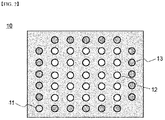
- FIG. 2 is a schematic diagram showing a measurement surface of an evaluation apparatus according to another embodiment of the present invention.
- the measuring unit includes: a ground probe 11; a plurality of voltage probes 12 arranged at different intervals from the ground probe; and current probes 13 arranged at regular intervals at an external side of a region in which the voltage probes are formed.
- the potential difference between each voltage probe 12 and the ground probe 11 is measured.
- a total of 25 voltage probes 12 are formed, and 5 voltage probes in a horizontal direction and 5 voltage probe in a vertical direction are arranged in a rectangular region.
- a ground probe 11 is positioned on one side of the measuring unit 10, and a current probe 13 is positioned outside the rectangular region in which the voltage probes 12 are arranged.
- the current probes 13 have a structure in which a total of 20 current probes are formed, 5 each on one side.
- Graphite as a negative electrode active material, cyanoethyl polyvinyl alcohol as a dispersant, and PVdF (polyvinylidene fluoride) as a binder were weighed in a weight ratio of 95.6 : 1 : 2 : 1.1, respectively, which was put in NMP and was mixed for 1 hour at 1,000 rpm in a Homo mixer, to thereby prepare a slurry for a negative electrode.
- the prepared slurry for negative electrode was applied to a copper foil having a thickness of 20 ⁇ m at a thickness of 100 ⁇ m. Then, the copper foil was dried at 40°C and was then rolled to thereby prepare a negative electrode.
- a slurry for negative electrode was prepared in the same manner as in Preparation Example 1.
- the prepared slurry for negative electrode was applied to a copper foil having a thickness of 20 ⁇ m at a thickness of 100 ⁇ m. Then, the copper foil was dried at 80°C and was then rolled to thereby prepare a negative electrode.
- a slurry for negative electrode was prepared in the same manner as in Preparation Example 1.
- the prepared slurry for negative electrode was applied to a copper foil having a thickness of 20 ⁇ m at a thickness of 100 ⁇ m. Then, the copper foil was dried at 120°C and was then rolled to thereby prepare a negative electrode.
- LiNi 0.5 Mn 0.3 Co 0.2 as positive electrode active material, Super C as conductive material, cyanoethyl polyvinyl alcohol as dispersion material, and PVdF as binder were weighed in a weight ratio of 95 : 3 : 0.3 : 1.7, respectively, which was then put in NMP and was mixed for 1 hour at 1,000 rpm in a Homo mixer, to thereby prepare a slurry for a positive electrode.
- the prepared slurry for positive electrode was applied to an aluminum foil having a thickness of 20 ⁇ m at a thickness of 100 ⁇ m. Then, the aluminum foil was dried at 80°C and was then rolled to thereby prepare a positive electrode.
- a slurry for positive electrode was prepared in the same manner as in Preparation Example 4.
- the prepared slurry for positive electrode was applied to an aluminum foil having a thickness of 20 ⁇ m at a thickness of 100 ⁇ m. Then, the aluminum foil was dried at 130°C and was then rolled to thereby prepare a positive electrode.
- the binder dispersibility was evaluated for the electrode specimens prepared in Preparation Examples 1 to 3.
- the evaluation apparatus illustrated in FIG. 1 was used, and the measuring unit of the apparatus includes: a ground probe; 6 voltage probes arranged at different intervals from the ground probe; and current probes arranged at regular intervals at an external side of a region in which the voltage probes are formed.
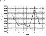
- FIG. 3 In a state in which a current was applied to the electrode mixture layer through a current probe, a potential difference was measured in each voltage probe. The measured results are shown in FIG. 3 . Referring to FIG. 3 , it was measured that the potential difference was the largest at point 5. This indicates the resistance from the upper portion to the lower portion of the mixture layer as point 5 is the farthest from the ground probe. The potential difference at points 2, 3 and 6 reflects the resistance of the upper portion of the mixture layer. And, at point 4, the potential difference was measured to be close to 0, and this is excluded from the evaluation.
- the measured value at the point 5 having the largest potential difference was set as the reference voltage
- the voltage difference ( ⁇ V) from the reference voltage was calculated for each point, and the result is shown in FIG. 4 .
- FIG. 4 it can be seen that the voltage difference ⁇ V at points 2, 3, and 6 increases as the drying temperature of the specimen increases.
- the fact that the difference ( ⁇ V) between the potential difference at points 2, 3 and 6 reflecting the resistance of only the upper portion and the potential difference at point 5 reflecting the resistance of the upper portion and the lower portion is large means that relatively more binders are distributed in the upper portion.
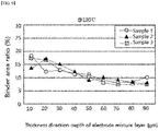
- FIG. 5 is a graph showing the dispersibility of the binder according to the depth of the mixture layer.
- the binder moves to the upper portion of the mixture layer according to the drying temperature of the electrode specimen. This corresponds to the result of Example 1 that the binder moves toward the upper portion of the mixture layer as the drying temperature of the electrode increases.
- the binder dispersibility was evaluated for the electrode specimens prepared in Preparation Examples 4 and 5.
- the evaluation apparatus illustrated in FIG. 1 was used, and the measuring unit of the apparatus includes: a ground probe; 6 voltage probes arranged at different intervals from the ground probe; and current probes arranged at regular intervals at an external side of a region in which the voltage probes are formed.
- FIG. 6 In a state in which a current was applied to the electrode mixture layer through a current probe, a potential difference was measured in each voltage probe. The measured results are shown in FIG. 6 . Referring to FIG. 6 , it was measured that the potential difference was the largest at point 5. This indicates the resistance from the upper portion to the lower portion of the mixture layer as point 5 is the farthest from the ground probe. The potential difference at points 2, 3 and 6 reflects the resistance of the upper portion of the mixture layer. And, at point 4, the potential difference was measured to be close to 0, and this is excluded from the evaluation.
- the measured value at the point 5 having the largest potential difference was set as the reference voltage
- the voltage difference ( ⁇ V) from the reference voltage was calculated for each point, and the result is shown in FIG. 7 .
- FIG. 7 it can be seen that the voltage difference ⁇ V at points 2, 3, and 6 increases as the drying temperature of the specimen increases.
- the fact that the difference ( ⁇ V) between the potential difference at points 2, 3 and 6 reflecting the resistance of only the upper portion and the potential difference at point 5 reflecting the resistance of the upper portion and the lower portion is large means that relatively more binders are distributed in the upper portion.
- FIG. 8 is a graph showing the experimental results for the electrode specimen according to Preparation Example 4
- FIG. 9 is a graph showing experimental results for an electrode specimen according to Preparation Example 5.
Landscapes
- Chemical & Material Sciences (AREA)
- Chemical Kinetics & Catalysis (AREA)
- Electrochemistry (AREA)
- General Chemical & Material Sciences (AREA)
- Physics & Mathematics (AREA)
- General Physics & Mathematics (AREA)
- Health & Medical Sciences (AREA)
- Life Sciences & Earth Sciences (AREA)
- Analytical Chemistry (AREA)
- Biochemistry (AREA)
- General Health & Medical Sciences (AREA)
- Immunology (AREA)
- Pathology (AREA)
- Manufacturing & Machinery (AREA)
- Engineering & Computer Science (AREA)
- Molecular Biology (AREA)
- Battery Electrode And Active Subsutance (AREA)
Abstract
Description
- The present invention relates to a method and an apparatus for evaluating the dispersibility in the thickness direction of a binder in an electrode mixture layer.
- This application claims the benefit of priority based on
Korean Patent Application No. 10-2019-0162497, filed on December 9, 2019 - As technologies for mobile devices are developed and demand for the mobile devices increases, there has been a rapid increase in demand for secondary batteries as energy sources. Among such secondary batteries, lithium secondary batteries, which exhibit a high energy density and operational potential, a long cycle life, and a low self-discharge rate have been commercialized and widely used.
- In recent years, there has been a growing interest in environmental issues, and as a result, recently, electric vehicles (EVs) and hybrid electric vehicles (HEVs), which can replace fossil-fueled vehicles such as gasoline vehicles and diesel vehicles, and the like are widely studied. Lithium secondary batteries having high energy density, high discharge voltage, and output stability are mainly studied and used as a power source for electric vehicles (EV) and hybrid electric vehicles (HEV).
- In general, such a lithium secondary battery is manufactured by embedding an electrode assembly including a positive electrode, a negative electrode, and a separator in a battery case in a state impregnated with an electrolyte solution. The electrode such as the positive electrode or negative electrode has a structure in which an electrode mixture layer is formed on one or both surfaces of a current collector. In order to manufacture the electrode mixture layer, an electrode slurry including an active material, a conductive material, and a binder is prepared, and the slurry is then applied to an electrode current collector, which is then dried and rolled.
- The performance of the lithium secondary battery is greatly affected by the manufactured electrode. For example, in the process of drying the electrode, a component in the mixture layer, particularly, a binder flows. The flow of the binder affects the interfacial bonding between the current collector and the mixture layer, and changes the conductivity in the electrode mixture layer. Therefore, there is a high need for a technology capable of effectively analyzing or evaluating the dispersibility of a binder in an electrode mixture layer.
- The present invention was invented in consideration of the above problems, and the present invention relates to a method and apparatus for evaluating the dispersibility in the thickness direction of a binder in an electrode mixture layer by a non-destructive method.
- The present invention relates to a method for evaluating the dispersibility of a binder in the thickness direction in an electrode mixture layer. In one example, the method according to the present invention includes:
- a step of setting an arbitrary reference point (no) on a surface of an electrode mixture layer in a state where current is applied to an electrode mixture layer, and measuring a potential difference (V) with each reference point (no) at n points having different separation distances from the set reference point (no) where n is an integer greater than or equal to 2;
- a step of setting any one potential difference among the measured potential differences as a reference voltage and calculating a voltage difference (ΔV) from the reference voltage; and
- a step of comparing the calculated voltage difference (ΔV) with a preset reference value, and calculating a dispersion in a thickness direction of a binder in the electrode mixture layer.
- In one example, the step of measuring the potential difference (V) includes:
- a process of calculating a potential difference (Vi) between a reference point (no) on the surface of the electrode mixture layer and a first point (n1) spaced apart from the reference point (no); and
- a process of calculating a potential difference (Vk) between the reference point (no) and a k-th point (nk) spaced from the reference point (no) by another interval where k is an integer in a range between 2 and n.
- In a specific example, in the step of measuring the potential difference V, the processes of calculating each potential difference are performed simultaneously or sequentially.
- In further another example, the step of measuring the potential difference (V) includes: a process of setting an arbitrary reference point (no) on the surface of the electrode mixture layer; a process of specifying n potential difference measurement points spaced apart from the set reference point (no) by a different distance; and a process of measuring the potential difference (V) between the reference point (no) and each voltage measurement point in a state where a current is applied to the electrode mixture layer.
- In a specific example, in the step of measuring the potential difference (V), the process of specifying n potential difference measurement points includes designating a rectangular region which is formed within a constant voltage measurement region and where, on average, p voltage probes in a horizontal direction and q voltage probes in a vertical direction are arranged at regular intervals, in which p and q are each 1 or more, but a product of p and q is an integer equal to n.
- In one example, in the method according to the present invention, at least two current application points are further included at an external side of n potential difference measurement points.
- In a specific example, in the step of calculating the voltage difference ΔV, the largest potential difference among the measured potential differences is set as the reference voltage.
- The present invention provides an apparatus for evaluating the dispersibility of a binder in the thickness direction in the electrode mixture layer. The apparatus is an apparatus for performing the method described above.
- In one example, the apparatus includes a measuring unit in which a number of probes are formed on a measurement surface in contact with an electrode mixture layer to be measured.
- Herein, the measuring unit includes:
- a ground probe;
- n voltage probes arranged at different intervals from the ground probe where n is an integer of 2 or more; and
- current probes arranged at regular intervals at an external side of a region in which the voltage probes are formed, and
- the potential difference between each voltage probe and the ground probe is measured in a state that the current is applied through the current probe.
- In a specific example, on average, p voltage probes in a horizontal direction and q voltage probes in a vertical direction are arranged on a rectangular region at regular intervals. Herein, p and q are each 1 or more, but a product of p and q is an integer equal to n. For example, p and q are each an integer of 3 to 8.
- In one example, the apparatus further includes a data processing unit configured to set one of potential differences measured from a measuring unit as a reference voltage, calculating a voltage difference (ΔV) from the reference voltage, and evaluate dispersibility in a thickness direction of a binder in an electrode mixture layer by comparing the calculated voltage difference (ΔV) with a preset reference value.
- According to the method and apparatus for evaluating the binder dispersibility in the electrode mixture layer according to the present invention, the dispersibility in the thickness direction of the binder in the electrode mixture layer can be evaluated in a non-destructive manner.
-
-
FIG. 1 is a schematic diagram showing a process of performing an evaluation method according to an embodiment of the present invention. -
FIG. 2 is a schematic diagram showing a measurement surface of an evaluation apparatus according to another embodiment of the present invention. -
FIGS. 3 and6 are graphs showing results of measuring a potential difference in each voltage probe in a state in which a current is applied to an electrode mixture layer through a current probe, respectively, according to an evaluation method according to an embodiment of the present invention. -
FIGS. 4 and7 are graphs showing the result of calculating a voltage difference (ΔV) from a reference voltage for each point according to an evaluation method according to one embodiment of the present invention, respectively. -
FIGS. 5 ,8 , and9 are graphs showing the dispersibility of a binder with respect to a cut surface after diagonally cutting an electrode mixture layer, respectively. - Hereinafter, the present invention will be described in detail with reference to the drawings. The terms and words used in the present specification and claims should not be construed as limited to ordinary or dictionary terms and the inventor may properly define the concept of the terms in order to best describe its invention. The terms and words should be construed as meaning and concept consistent with the technical idea of the present invention.
- The present invention provides a method for evaluating the dispersibility of a binder in the thickness direction in the electrode mixture layer. In one example, the method according to the present invention includes: a step of setting an arbitrary reference point (no) on a surface of an electrode mixture layer in a state where current is applied to the electrode mixture layer, and measuring a potential difference (V) with each reference point (no) at n points having different separation distances from the set reference point (no) where n is an integer greater than or equal to 2; a step of setting any one potential difference among the measured potential differences as a reference voltage and calculating a voltage difference (ΔV) from the reference voltage; and a step of comparing the calculated voltage difference (ΔV) with a preset reference value, and calculating a dispersion in a thickness direction of a binder in the electrode mixture layer.
- In the step of measuring the potential difference V with the reference point (no), the points for measuring the potential difference are two or more points, and specifically, may be 2 to 100 points or 5 to 60 points. If the number of points for measuring the potential difference increases, the reliability of the evaluation can be increased, but the manufacturing cost of the equipment performing the evaluation method increases. The points at which the potential difference is measured should have at least one point having a different separation distance from the reference point (no), and a case where two different points have the same separation distance from the reference point (no) may also be included.
- In the evaluation method according to the present invention, a potential difference is measured at two or more points having different separation distances from the surface of the electrode mixture layer. Based on the measured results, by setting a reference voltage and calculating a voltage difference for each point, it is possible to check the dispersibility of the binder in the electrode mixture layer. Conventionally, in order to evaluate the dispersibility of the binder in the electrode mixture layer, the electrode mixture layer to be evaluated was cut and the degree of dispersion of the binder on the cut surface was measured using IR or Raman spectrum. However, the existing evaluation method is a destructive method in that the electrode mixture layer to be evaluated should be cut. On the other hand, the present invention can evaluate the dispersibility of the binder in the electrode mixture layer by a non-destructive method.
- In one example, the step of measuring the potential difference (V) includes: a process of calculating a potential difference (Vi) between a reference point (no) on the surface of the electrode mixture layer and a first point (n1) spaced apart from the reference point (no); and a process of calculating a potential difference (Vk) between the reference point (no) and a k-th point (nk) spaced from the reference point (no) by another interval where k is an integer in a range between 2 and n.
- In a specific embodiment, in the step of measuring the potential difference V, the processes of calculating each potential difference are performed simultaneously or sequentially. For example, the step of measuring the potential difference V may be performed using an apparatus in which a plurality of voltage probes are formed on a measurement surface. In this case, it is possible to measure the potential difference at a plurality of points at the same time in a state that a current has been applied to the electrode mixture layer. Alternatively, it is also possible to measure the potential difference at a plurality of points sequentially in a state in which a current has been applied to the electrode mixture layer.
- In further another example, the step of measuring the potential difference (V) includes: a process of setting an arbitrary reference point (no) on the surface of the electrode mixture layer; a process of specifying n potential difference measurement points spaced apart from the set reference point (no) by a different distance; and a process of measuring the potential difference (V) between the reference point (no) and each voltage measurement point in a state where a current is applied to the electrode mixture layer. For example, the step of measuring the potential difference V may be performed using an apparatus in which a ground probe and a plurality of voltage probes are formed on a measurement surface. In addition, the measurement surface may have a structure in which a current probe for applying a current is formed together.
- In a specific example, in the step of measuring the potential difference (V), the process of specifying n potential difference measurement points includes designating a rectangular region which is formed within a constant voltage measurement region and where, on average, p voltage probes in a horizontal direction and q voltage probes in a vertical direction are arranged at regular intervals, in which p and q are each 1 or more, but a product of p and q is an integer equal to n. This means a structure in which points measuring the potential difference are arranged in a rectangular area. This is suggested as an example, and a structure in which points measuring the potential difference may be arranged in a radial, semicircular or circular shape, or may also be arranged in a form of a polygon such as a triangle or a hexagon.
- In one embodiment, the evaluation method further includes two or more current application points outside the n potential difference measurement points. This means measuring the potential difference at each point in a state where a current is applied to the electrode mixture layer. For example, the current application point may be formed outside the point where the potential difference is measured.
- In another embodiment, in the step of calculating the voltage difference ΔV, the largest potential difference among the measured potential differences is set as the reference voltage. In the evaluation method according to the present invention, a potential difference is measured at a plurality of points in the electrode mixture layer. Among the measured potential differences, the point showing the largest potential difference can be interpreted as reflecting the resistance of both the upper and lower portions of the electrode mixture layer. However, points at which the measured potential difference is substantially close to "0" may be excluded from the evaluation.
- In addition, the present invention provides an evaluation apparatus for performing the evaluation method described above. The evaluation apparatus is an evaluation apparatus for evaluating the dispersibility in the thickness direction of the binder in the electrode mixture layer. In one example, the apparatus according to the present invention includes a measuring unit in which a number of probes are formed on a measurement surface in contact with an electrode mixture layer to be measured. Herein, the measuring unit includes: a ground probe; n voltage probes arranged at different intervals from the ground probe where n is an integer of 2 or more; and current probes arranged at regular intervals at an external side of a region in which the voltage probes are formed. In addition, the potential difference between each voltage probe and the ground probe is measured in a state that the current is applied through the current probe.
- Two or more voltage probes may be formed, and specifically, 2 to 100 or 5 to 60 voltage probes may be formed. If the number of voltage probes increases, the reliability of evaluation can be increased, but the unit cost of the apparatus increases. The position of the voltage probe should be at least one point having a different separation distance from the ground probe, but may include a case where two different voltage probes have the same separation distance as the ground probe.
- In a specific example, on average, p voltage probes in a horizontal direction and q voltage probes in a vertical direction are arranged on a rectangular region at regular intervals. Herein, p and q are each 1 or more, but a product of p and q is an integer equal to n. For example, p and q are each an integer of 3 to 8. The arrangement of the voltage probes refers to a structure in which a plurality of voltage probes are arranged in a rectangular area. This is suggested as an example, and includes cases in which the voltage probes are arranged in various forms described above.
- In one example, the apparatus further includes a data processing unit configured to set one of potential differences measured from a measuring unit as a reference voltage, calculating a voltage difference (ΔV) from the reference voltage, and evaluate dispersibility in a thickness direction of a binder in an electrode mixture layer by comparing the calculated voltage difference (ΔV) with a preset reference value. The evaluation apparatus according to the present invention may process the measured result through the data processing unit and check the degree of dispersion of the binder in the electrode mixture layer.
- In addition, the electrode to be evaluated for the binder dispersibility in the present invention is a positive electrode or a negative electrode of the battery. The battery is a secondary battery, for example, a lithium secondary battery. The lithium secondary battery is a generic term for a case containing lithium in a secondary battery, and specifically includes a positive electrode, a negative electrode, and a separator interposed between the positive electrode and the negative electrode. Hereinafter, specific components of each electrode will be described, but the scope of the present invention is not limited thereto.
- The positive electrode has a structure in which a positive electrode mixture layer is stacked on one or both sides of a positive electrode current collector. The positive electrode active materials may each independently be a lithium-containing oxide, and may be the same or different. A lithium-containing transition metal oxide may be used as the lithium-containing oxide. In one example, the positive electrode mixture layer includes a conductive material and a binder polymer in addition to the positive electrode active material, and if necessary, may further include a positive electrode additive commonly used in the art.
- The positive electrode active material may be a lithium-containing oxide, and may be the same or different. A lithium-containing transition metal oxide may be used as the lithium-containing oxide.
- For example, the lithium-containing transition metal oxide may be any one or a mixture of two or more selected from the group consisting of LixCoO2(0.5<x<1.3), LixNiO2(0.5<x<1.3), LixMnO2(0.5<x<1.3), LixMn2O4(0.5<x<1.3), Lix(NiaCobMnc)O2(0.5<x<1.3, 0<a<1, 0<b<1, 0<c<1, a+b+c=1), LixNi1-yCoyO2(0.5<x<1.3, 0<y<1), LixCo1-yMnyO2(0.5<x<1.3, 0≤y<1), LixNi1-yMnyO2(0.5<x<1.3, O≤y<1), Lix(NiaCobMnc)O4(0.5<x<1.3, 0<a<2, 0<b<2, 0<c<2, a+b+c=2), LixMn2-zNizO4(0.5<x<1.3, 0<z<2), LixMn2-zCozO4(0.5<x<1.3, 0<z<2), LixCoPO4(0.5<x<1.3) and LixFePO4(0.5<x<1.3), and the lithium-containing transition metal oxide may be coated with a metal or metal oxide such as aluminum (Al). Further, in addition to the lithium-containing transition metal oxide, one or more of sulfide, selenide, and halide may be used.
- The positive electrode active material may be included in the range of 90 to 99 wt% in the positive electrode active material layer. When the content of the positive electrode active material satisfies the above range, it is advantageous in terms of manufacturing a high-capacity battery and providing sufficient conductivity of the positive electrode or adhesion between electrode materials.
- The current collector used for the positive electrode is a metal having high conductivity, and any metal which the positive electrode active material slurry may be easily attached to and which is not reactive in the voltage range of the secondary battery can be used. Specifically, non-limiting examples of the current collector for the positive electrode include aluminum, nickel, or a foil manufactured by a combination thereof.
- The positive electrode active material layer further includes a conductive material. The conductive material is usually added in an amount of 1 to 30% by weight based on the total weight of the mixture including the positive electrode active material. Such a conductive material is not particularly limited as long as it has conductivity without causing a chemical change in the secondary battery. For example, one or more selected from the group consisting of graphite such as natural graphite or artificial graphite; carbon black such as carbon black, acetylene black, ketjen black, channel black, furnace black, lamp black, or thermal black; conductive fiber such as carbon fiber or metal fiber; metal powder such as carbon fluoride, aluminum, or nickel powder; conductive whiskey such as zinc oxide or potassium titanate; conductive metal oxide such as titanium oxide; and polyphenylene derivative may be used as the conductive material.
- As the binder component, a binder polymer commonly used in the art may be used without limitation. For example, various kinds of binders such as polyvinylidene fluoride-co-hexafluoropropylene (PVDF-co-HFP), polyvinylidene fluoride (PVDF), polyacrylonitrile, polymethyl methacrylate, styrene-butadiene rubber (SBR), and carboxyl methyl cellulose (CMC) may be used.
- Further, the negative electrode has a structure in which a negative electrode mixture layer is stacked on one or both sides of a negative electrode current collector. In one example, the negative electrode mixture layer includes a negative electrode active material, a conductive material, and a binder polymer, and if necessary, may further include a negative electrode additive commonly used in the art.
- The negative electrode active material may include a carbon material, lithium metal, silicon or tin. When a carbon material is used as the negative electrode active material, both low crystalline carbon and high crystalline carbon may be used. Representative examples of low crystalline carbon include soft carbon and hard carbon are typical. Representative examples of high crystalline carbon include natural graphite, kish graphite, pyrolytic carbon, mesophase pitch based carbon fiber, mesocarbon microbeads, mesophase pitches, and high-temperature calcined carbons such as petroleum or coal tar pitch derived cokes.
- Non-limiting examples of the current collector used for the negative electrode include copper, gold, nickel, or a foil manufactured by a copper alloy or a combination thereof. In addition, the current collector may be used by stacking substrates made of the above materials.
- In addition, the negative electrode may include a conductive material and a binder commonly used in the art.
- Hereinafter, the present invention will be described in more detail through drawings and the like.
-
FIG. 1 is a schematic diagram showing a process of performing an evaluation method according to an embodiment of the present invention. Referring toFIG. 1 , an apparatus for evaluating the dispersibility of a binder in an electrode mixture layer includes a measuringunit 10 in which a plurality of probes are formed. The measuring unit includes: aground probe 11; a plurality of voltage probes 12 arranged at different intervals from the ground probe; andcurrent probes 13 arranged at regular intervals at an external side of a region in which the voltage probes are formed. In a state in which current is applied to theelectrode mixture layer 21 through thecurrent probe 13, eachvoltage probe 12 measures a potential difference with theground probe 11. - The
electrode 20 to be evaluated has a structure in which amixture layer 21 is formed on both surfaces of thecurrent collector 22. For example, thecurrent collector 22 is formed of aluminum foil, and themixture layer 21 is a positive electrode mixture layer containing lithium. - Each probe measures a potential, and a potential
difference measurement result 30 is calculated. The potential measured by theground probe 11 becomes the reference potential (0), and a potential difference for each point is derived from the difference between the reference potential (0) and the potentials (1 to 4) measured by each voltage probe. -
FIG. 2 is a schematic diagram showing a measurement surface of an evaluation apparatus according to another embodiment of the present invention. Referring toFIG. 2 , the measuring unit includes: aground probe 11; a plurality of voltage probes 12 arranged at different intervals from the ground probe; andcurrent probes 13 arranged at regular intervals at an external side of a region in which the voltage probes are formed. In a state in which current is applied to theelectrode mixture layer 21 through thecurrent probe 13, the potential difference between eachvoltage probe 12 and theground probe 11 is measured. A total of 25voltage probes 12 are formed, and 5 voltage probes in a horizontal direction and 5 voltage probe in a vertical direction are arranged in a rectangular region. - A
ground probe 11 is positioned on one side of the measuringunit 10, and acurrent probe 13 is positioned outside the rectangular region in which the voltage probes 12 are arranged. The current probes 13 have a structure in which a total of 20 current probes are formed, 5 each on one side. - Hereinafter, the present invention will be described in more detail through examples. However, the embodiments described in the specification and the configurations described in the drawings are only the most preferred embodiments of the present invention, and do not represent all of the technical ideas of the present invention. It is to be understood that there may be various equivalents and variations in place of them at the time of filing the present application.
- Graphite as a negative electrode active material, cyanoethyl polyvinyl alcohol as a dispersant, and PVdF (polyvinylidene fluoride) as a binder were weighed in a weight ratio of 95.6 : 1 : 2 : 1.1, respectively, which was put in NMP and was mixed for 1 hour at 1,000 rpm in a Homo mixer, to thereby prepare a slurry for a negative electrode.
- The prepared slurry for negative electrode was applied to a copper foil having a thickness of 20 µm at a thickness of 100 µm. Then, the copper foil was dried at 40°C and was then rolled to thereby prepare a negative electrode.
- A slurry for negative electrode was prepared in the same manner as in Preparation Example 1. The prepared slurry for negative electrode was applied to a copper foil having a thickness of 20 µm at a thickness of 100 µm. Then, the copper foil was dried at 80°C and was then rolled to thereby prepare a negative electrode.
- A slurry for negative electrode was prepared in the same manner as in Preparation Example 1. The prepared slurry for negative electrode was applied to a copper foil having a thickness of 20 µm at a thickness of 100 µm. Then, the copper foil was dried at 120°C and was then rolled to thereby prepare a negative electrode.
- LiNi0.5Mn0.3Co0.2 as positive electrode active material, Super C as conductive material, cyanoethyl polyvinyl alcohol as dispersion material, and PVdF as binder were weighed in a weight ratio of 95 : 3 : 0.3 : 1.7, respectively, which was then put in NMP and was mixed for 1 hour at 1,000 rpm in a Homo mixer, to thereby prepare a slurry for a positive electrode.
- The prepared slurry for positive electrode was applied to an aluminum foil having a thickness of 20 µm at a thickness of 100 µm. Then, the aluminum foil was dried at 80°C and was then rolled to thereby prepare a positive electrode.
- A slurry for positive electrode was prepared in the same manner as in Preparation Example 4. The prepared slurry for positive electrode was applied to an aluminum foil having a thickness of 20 µm at a thickness of 100 µm. Then, the aluminum foil was dried at 130°C and was then rolled to thereby prepare a positive electrode.
- Using the evaluation apparatus according to the present invention, the binder dispersibility was evaluated for the electrode specimens prepared in Preparation Examples 1 to 3.
- Specifically, the evaluation apparatus illustrated in
FIG. 1 was used, and the measuring unit of the apparatus includes: a ground probe; 6 voltage probes arranged at different intervals from the ground probe; and current probes arranged at regular intervals at an external side of a region in which the voltage probes are formed. - In a state in which a current was applied to the electrode mixture layer through a current probe, a potential difference was measured in each voltage probe. The measured results are shown in
FIG. 3 . Referring toFIG. 3 , it was measured that the potential difference was the largest atpoint 5. This indicates the resistance from the upper portion to the lower portion of the mixture layer aspoint 5 is the farthest from the ground probe. The potential difference atpoints point 4, the potential difference was measured to be close to 0, and this is excluded from the evaluation. - Then, the measured value at the
point 5 having the largest potential difference was set as the reference voltage, the voltage difference (ΔV) from the reference voltage was calculated for each point, and the result is shown inFIG. 4 . Referring toFIG. 4 , it can be seen that the voltage difference ΔV atpoints points point 5 reflecting the resistance of the upper portion and the lower portion is large means that relatively more binders are distributed in the upper portion. - This means that the binder moves toward the upper portion during the drying process of the electrode, and a larger amount of the binder is placed on the upper portion as the drying temperature increases.
- Binder dispersibility was verified for the electrode specimens prepared in Preparation Examples 1 to 3. Each electrode specimen was obliquely cut at an angle of 1.5°, and then IR and Raman spectra were measured for the inclined surface to confirm actual binder dispersibility.
FIG. 5 is a graph showing the dispersibility of the binder according to the depth of the mixture layer. - Referring to
FIG. 5 , it can be seen that the binder moves to the upper portion of the mixture layer according to the drying temperature of the electrode specimen. This corresponds to the result of Example 1 that the binder moves toward the upper portion of the mixture layer as the drying temperature of the electrode increases. - Using the evaluation apparatus according to the present invention, the binder dispersibility was evaluated for the electrode specimens prepared in Preparation Examples 4 and 5.
- Specifically, the evaluation apparatus illustrated in
FIG. 1 was used, and the measuring unit of the apparatus includes: a ground probe; 6 voltage probes arranged at different intervals from the ground probe; and current probes arranged at regular intervals at an external side of a region in which the voltage probes are formed. - In a state in which a current was applied to the electrode mixture layer through a current probe, a potential difference was measured in each voltage probe. The measured results are shown in
FIG. 6 . Referring toFIG. 6 , it was measured that the potential difference was the largest atpoint 5. This indicates the resistance from the upper portion to the lower portion of the mixture layer aspoint 5 is the farthest from the ground probe. The potential difference atpoints point 4, the potential difference was measured to be close to 0, and this is excluded from the evaluation. - Then, the measured value at the
point 5 having the largest potential difference was set as the reference voltage, the voltage difference (ΔV) from the reference voltage was calculated for each point, and the result is shown inFIG. 7 . Referring toFIG. 7 , it can be seen that the voltage difference ΔV atpoints points point 5 reflecting the resistance of the upper portion and the lower portion is large means that relatively more binders are distributed in the upper portion. - This means that the binder moves toward the upper portion during the drying process of the electrode, and a larger amount of the binder is placed on the upper portion as the drying temperature increases.
- Binder dispersibility was verified for the electrode specimens prepared in Preparation Examples 4 and 5. Each electrode specimen was obliquely cut at an angle of 1.5°, and then IR and Raman spectra were measured for the inclined surface to confirm actual binder dispersibility. To check the dispersibility, the experiment was repeated three times for each specimen.
FIG. 8 is a graph showing the experimental results for the electrode specimen according to Preparation Example 4, andFIG. 9 is a graph showing experimental results for an electrode specimen according to Preparation Example 5. - Referring to
FIG. 8 , it can be seen that in the electrode specimen of Preparation Example 4 dried at 80°C, the binder was evenly dispersed in the thickness direction of the mixture layer. On the other hand, referring toFIG. 9 , it can be seen that in the electrode specimen of Preparation Example 5 dried at 130°C, the binder was somewhat concentrated toward the upper portion of the mixture layer and dispersed. - This corresponds to the result of Example 2 that the binder moves toward the upper portion of the mixture layer as the drying temperature of the electrode increases.
-
- 10:
- measuring unit
- 11:
- ground probe
- 12:
- voltage probe
- 13:
- current probe
- 20:
- electrode
- 21:
- mixture layer
- 22:
- current collector
- 30:
- Potential difference measurement result
Claims (11)
- A method for evaluating dispersibility of a binder in thickness direction in an electrode mixture layer, comprising:setting an arbitrary reference point (no) on a surface of the electrode mixture layer in a state where current is applied to the electrode mixture layer, and measuring a potential difference (V) with the set reference point (no) at n points each having different separation distances from the set reference point (no) where n is an integer greater than or equal to 2;setting any one potential difference among the measured potential differences as a reference voltage and calculating a voltage difference (ΔV) from the reference voltage; andcomparing the calculated voltage difference (ΔV) with a preset reference value, and calculating a dispersion in a thickness direction of a binder in the electrode mixture layer.
- The method of claim 1, wherein the measuring the potential difference (V) comprises:calculating a potential difference (VI) between the reference point (no) on the surface of the electrode mixture layer and a first point (n1) spaced apart from the reference point (no); andcalculating a potential difference (Vk) between the reference point (no) and a kth point (nk) spaced from the reference point (no) by another interval where k is an integer in a range between 2 and n.
- The method of claim 2, wherein in the measuring the potential difference (V), calculating each potential difference are performed simultaneously or sequentially.
- The method of claim 1, wherein the measuring the potential difference (V) comprises:specifying n potential difference measurement points spaced apart from the set reference point (no) by a different distance; andmeasuring the potential difference (V) between the reference point (no) and each voltage measurement point in a state where a current is applied to the electrode mixture layer.
- The method of claim 4, wherein in the measuring the potential difference (V), the specifying n potential difference measurement points includes designating a rectangular region which is formed within a constant voltage measurement region and where, on average, p voltage probes in a horizontal direction and q voltage probes in a vertical direction are arranged at regular intervals, and
wherein p and q are each an integer of 1 or more, and a product of p and q is an integer equal to n. - The method of claim 1, wherein at least two current application points are further included at an external side of n potential difference measurement points.
- The method of claim 1, wherein in the calculating the voltage difference (ΔV), a largest potential difference among the measured potential differences is set as the reference voltage.
- An apparatus for evaluating dispersibility of a binder in a thickness direction in an electrode mixture layer, comprising:a measuring unit in which a number of probes are formed on a measurement surface in contact with the electrode mixture layer to be measured,wherein the measuring unit comprises:a ground probe;n voltage probes arranged at different intervals from the ground probe where n is an integer of 2 or more; andcurrent probes arranged at regular intervals at an external side of a region in which the voltage probes are formed,wherein the potential difference between each voltage probe and the ground probe is measured in a state that the current is applied through the current probe.
- The apparatus of claim 8, wherein, on average, p voltage probes in a horizontal direction and q voltage probes in a vertical direction are arranged on a rectangular region at regular intervals,
wherein p and q are each an integer of 1 or more, and a product of p and q is an integer equal to n. - The apparatus of claim 9, wherein p and q are each an integer of 3 to 8.
- The apparatus of claim 8, further comprising a data processing unit configured to set one of potential differences measured from the measuring unit as a reference voltage, calculating a voltage difference (ΔV) from the reference voltage, and evaluate dispersibility in a thickness direction of a binder in an electrode mixture layer by comparing the calculated voltage difference (ΔV) with a preset reference value.
Applications Claiming Priority (2)
| Application Number | Priority Date | Filing Date | Title |
|---|---|---|---|
| KR1020190162497A KR102814154B1 (en) | 2019-12-09 | 2019-12-09 | Evaluation Method and Device for Dispersibility of Binder in Electrode Mixture Layer |
| PCT/KR2020/016370 WO2021118100A1 (en) | 2019-12-09 | 2020-11-19 | Method and device for evaluating dispersion of binder in electrode mixture layer |
Publications (3)
| Publication Number | Publication Date |
|---|---|
| EP3988931A1 true EP3988931A1 (en) | 2022-04-27 |
| EP3988931A4 EP3988931A4 (en) | 2022-08-03 |
| EP3988931B1 EP3988931B1 (en) | 2024-11-06 |
Family
ID=76329018
Family Applications (1)
| Application Number | Title | Priority Date | Filing Date |
|---|---|---|---|
| EP20899245.3A Active EP3988931B1 (en) | 2019-12-09 | 2020-11-19 | Method and device for evaluating dispersion of binder in electrode mixture layer |
Country Status (8)
| Country | Link |
|---|---|
| US (1) | US11913782B2 (en) |
| EP (1) | EP3988931B1 (en) |
| KR (1) | KR102814154B1 (en) |
| CN (1) | CN114174816B (en) |
| ES (1) | ES2994580T3 (en) |
| HU (1) | HUE069328T2 (en) |
| PL (1) | PL3988931T3 (en) |
| WO (1) | WO2021118100A1 (en) |
Family Cites Families (21)
| Publication number | Priority date | Publication date | Assignee | Title |
|---|---|---|---|---|
| JP4842549B2 (en) | 2005-03-08 | 2011-12-21 | 日置電機株式会社 | Short detection device |
| KR20070087857A (en) * | 2005-12-29 | 2007-08-29 | 삼성에스디아이 주식회사 | Lithium secondary battery |
| JP2007309797A (en) | 2006-05-18 | 2007-11-29 | Espec Corp | Resistance measuring device and method |
| KR20090128161A (en) * | 2008-06-10 | 2009-12-15 | 국방과학연구소 | Dispersibility Evaluation Method of Conductive Nanomaterials in Polymeric Composites Using Volumetric Resistance Measurement |
| JP5146225B2 (en) | 2008-09-25 | 2013-02-20 | 株式会社デンソー | Current measuring device |
| KR101685461B1 (en) * | 2011-09-05 | 2016-12-20 | 가부시키가이샤 니혼 마이크로닉스 | Apparatus and Method for Evaluating Sheet-like Battery |
| EP2755270B1 (en) * | 2011-09-09 | 2020-06-24 | Toyota Jidosha Kabushiki Kaisha | Secondary cell inspecting method |
| JP5975274B2 (en) * | 2012-07-27 | 2016-08-23 | トヨタ自動車株式会社 | Electrode inspection method and use thereof |
| JP6345399B2 (en) | 2012-09-28 | 2018-06-20 | 株式会社住化分析センター | Electrode evaluation method |
| EP2997612B1 (en) * | 2013-05-17 | 2019-11-20 | Miltec Corporation | Actinic and electron beam radiation curable water based electrode binders and electrodes incorporating same |
| JP2015069868A (en) | 2013-09-30 | 2015-04-13 | 日本電気株式会社 | Device and method for manufacturing electrode for lithium ion secondary battery |
| JP6472664B2 (en) * | 2014-04-14 | 2019-02-20 | 日置電機株式会社 | Measuring apparatus and measuring method |
| KR101748929B1 (en) | 2015-02-05 | 2017-06-19 | 주식회사 엘지화학 | Measuring method of binder distribution in electrode |
| KR101982571B1 (en) | 2015-10-08 | 2019-05-27 | 주식회사 엘지화학 | Method for measuring distribution of binder in electrode |
| KR102099908B1 (en) | 2015-11-26 | 2020-04-10 | 주식회사 엘지화학 | Reference electrode with improved durability and secondary battery comprising the same |
| KR102070555B1 (en) | 2015-12-03 | 2020-01-29 | 주식회사 엘지화학 | Method for preparing a lithium secondary battery, method for measuring the dispersity of conductive material in pre-dispersion liquid, and method for measuring the dispersity of active material in slurry for forming electrode |
| JP6702426B2 (en) * | 2016-10-26 | 2020-06-03 | 三菱電機株式会社 | Inspection device and inspection method |
| KR102255489B1 (en) | 2017-11-09 | 2021-06-03 | 주식회사 엘지에너지솔루션 | System and method for evaluating performance of electrode |
| KR102204699B1 (en) * | 2018-01-31 | 2021-01-18 | 주식회사 엘지화학 | Method and apparatus for evaluating safety of secondary battery |
| JP2019153469A (en) | 2018-03-02 | 2019-09-12 | 株式会社住化分析センター | Evaluation method |
| CN108519407B (en) * | 2018-05-28 | 2021-06-01 | 湖北亿纬动力有限公司 | Method for evaluating dispersibility of conductive slurry of lithium ion battery |
-
2019
- 2019-12-09 KR KR1020190162497A patent/KR102814154B1/en active Active
-
2020
- 2020-11-19 CN CN202080052573.2A patent/CN114174816B/en active Active
- 2020-11-19 EP EP20899245.3A patent/EP3988931B1/en active Active
- 2020-11-19 US US17/634,409 patent/US11913782B2/en active Active
- 2020-11-19 PL PL20899245.3T patent/PL3988931T3/en unknown
- 2020-11-19 ES ES20899245T patent/ES2994580T3/en active Active
- 2020-11-19 HU HUE20899245A patent/HUE069328T2/en unknown
- 2020-11-19 WO PCT/KR2020/016370 patent/WO2021118100A1/en not_active Ceased
Also Published As
| Publication number | Publication date |
|---|---|
| US11913782B2 (en) | 2024-02-27 |
| HUE069328T2 (en) | 2025-02-28 |
| WO2021118100A1 (en) | 2021-06-17 |
| ES2994580T3 (en) | 2025-01-28 |
| KR102814154B1 (en) | 2025-05-28 |
| EP3988931A4 (en) | 2022-08-03 |
| PL3988931T3 (en) | 2025-02-10 |
| KR20210072313A (en) | 2021-06-17 |
| US20220316853A1 (en) | 2022-10-06 |
| EP3988931B1 (en) | 2024-11-06 |
| CN114174816A (en) | 2022-03-11 |
| CN114174816B (en) | 2024-06-11 |
Similar Documents
| Publication | Publication Date | Title |
|---|---|---|
| Zhang et al. | Cycle-life characterization of automotive lithium-ion batteries with LiNiO2 cathode | |
| CN114788042B (en) | Positive electrode for lithium secondary battery and lithium secondary battery including the positive electrode | |
| JP6179498B2 (en) | Method for producing negative electrode for non-aqueous electrolyte secondary battery | |
| KR102267599B1 (en) | A Method for predicting process efficiency of an electrode slurry and selecting a binder for an electrode | |
| Linsenmann et al. | Comparing the lithiation and sodiation of a hard carbon anode using in situ impedance spectroscopy | |
| JP6245228B2 (en) | Inspection method for all-solid-state secondary battery and method for manufacturing all-solid-state secondary battery using the inspection method | |
| CN110611076A (en) | Lithium ion battery positive pole piece and preparation method thereof | |
| JP2016526257A (en) | Conductive carbon for lithium-ion batteries | |
| CN102918687A (en) | Method of evaluating negative active material and negative active material | |
| KR102717687B1 (en) | All solid state battery | |
| KR102477915B1 (en) | Method of producing lithium-ion battery | |
| KR102310584B1 (en) | Electrodes and batteries containing different carbon black particles | |
| KR20210063029A (en) | Positive electrod for secondary battery having the second-layered structure comprising electrode active material having different property in each layer | |
| KR101947565B1 (en) | Collector and electrode structure, non-aqueous electrolyte cell, electrical double layer capacitor, lithium ion capacitor, or electricity storage component using same | |
| KR20130038302A (en) | Anode active material | |
| EP3988931B1 (en) | Method and device for evaluating dispersion of binder in electrode mixture layer | |
| US20230076153A1 (en) | Degenerate cell manufacturing method and degenerate cell evaluation method | |
| US11616234B2 (en) | Negative electrode for rapidly rechargeable lithium secondary battery and manufacturing method thereof | |
| CN114459963B (en) | An evaluation method for lithium ion diffusion ability in cathode materials | |
| KR102886240B1 (en) | Method and apparatus for measuring resistance for battery welding inspection using multiplexer | |
| EP3916849A1 (en) | Cathode having increased hardness for improved safety, manufacturing method therefor, and secondary battery comprising same | |
| KR102663792B1 (en) | Method for Determining Dispersibility of Electrode Material | |
| KR20090111289A (en) | Anode active material for secondary battery, electrode for secondary battery comprising same, secondary battery and method for manufacturing same | |
| JP7570767B2 (en) | Non-destructive detection method for cell failure | |
| KR20250020008A (en) | A determination method for a suitability of magnetic alignment of negative electrode slurry |
Legal Events
| Date | Code | Title | Description |
|---|---|---|---|
| STAA | Information on the status of an ep patent application or granted ep patent |
Free format text: STATUS: THE INTERNATIONAL PUBLICATION HAS BEEN MADE |
|
| PUAI | Public reference made under article 153(3) epc to a published international application that has entered the european phase |
Free format text: ORIGINAL CODE: 0009012 |
|
| STAA | Information on the status of an ep patent application or granted ep patent |
Free format text: STATUS: REQUEST FOR EXAMINATION WAS MADE |
|
| 17P | Request for examination filed |
Effective date: 20220120 |
|
| AK | Designated contracting states |
Kind code of ref document: A1 Designated state(s): AL AT BE BG CH CY CZ DE DK EE ES FI FR GB GR HR HU IE IS IT LI LT LU LV MC MK MT NL NO PL PT RO RS SE SI SK SM TR |
|
| A4 | Supplementary search report drawn up and despatched |
Effective date: 20220704 |
|
| RIC1 | Information provided on ipc code assigned before grant |
Ipc: G01R 31/36 20200101ALI20220628BHEP Ipc: H01M 4/62 20060101ALI20220628BHEP Ipc: H01M 4/04 20060101ALI20220628BHEP Ipc: G01N 27/416 20060101AFI20220628BHEP |
|
| DAV | Request for validation of the european patent (deleted) | ||
| DAX | Request for extension of the european patent (deleted) | ||
| GRAP | Despatch of communication of intention to grant a patent |
Free format text: ORIGINAL CODE: EPIDOSNIGR1 |
|
| STAA | Information on the status of an ep patent application or granted ep patent |
Free format text: STATUS: GRANT OF PATENT IS INTENDED |
|
| INTG | Intention to grant announced |
Effective date: 20240624 |
|
| P01 | Opt-out of the competence of the unified patent court (upc) registered |
Free format text: CASE NUMBER: APP_39352/2024 Effective date: 20240702 |
|
| GRAS | Grant fee paid |
Free format text: ORIGINAL CODE: EPIDOSNIGR3 |
|
| GRAA | (expected) grant |
Free format text: ORIGINAL CODE: 0009210 |
|
| STAA | Information on the status of an ep patent application or granted ep patent |
Free format text: STATUS: THE PATENT HAS BEEN GRANTED |
|
| AK | Designated contracting states |
Kind code of ref document: B1 Designated state(s): AL AT BE BG CH CY CZ DE DK EE ES FI FR GB GR HR HU IE IS IT LI LT LU LV MC MK MT NL NO PL PT RO RS SE SI SK SM TR |
|
| REG | Reference to a national code |
Ref country code: GB Ref legal event code: FG4D |
|
| REG | Reference to a national code |
Ref country code: CH Ref legal event code: EP |
|
| REG | Reference to a national code |
Ref country code: DE Ref legal event code: R096 Ref document number: 602020041079 Country of ref document: DE |
|
| REG | Reference to a national code |
Ref country code: IE Ref legal event code: FG4D |
|
| REG | Reference to a national code |
Ref country code: SE Ref legal event code: TRGR |
|
| REG | Reference to a national code |
Ref country code: ES Ref legal event code: FG2A Ref document number: 2994580 Country of ref document: ES Kind code of ref document: T3 Effective date: 20250128 |
|
| REG | Reference to a national code |
Ref country code: HU Ref legal event code: AG4A Ref document number: E069328 Country of ref document: HU |
|
| REG | Reference to a national code |
Ref country code: LT Ref legal event code: MG9D |
|
| REG | Reference to a national code |
Ref country code: NL Ref legal event code: MP Effective date: 20241106 |
|
| PG25 | Lapsed in a contracting state [announced via postgrant information from national office to epo] |
Ref country code: PT Free format text: LAPSE BECAUSE OF FAILURE TO SUBMIT A TRANSLATION OF THE DESCRIPTION OR TO PAY THE FEE WITHIN THE PRESCRIBED TIME-LIMIT Effective date: 20250306 Ref country code: IS Free format text: LAPSE BECAUSE OF FAILURE TO SUBMIT A TRANSLATION OF THE DESCRIPTION OR TO PAY THE FEE WITHIN THE PRESCRIBED TIME-LIMIT Effective date: 20250306 Ref country code: HR Free format text: LAPSE BECAUSE OF FAILURE TO SUBMIT A TRANSLATION OF THE DESCRIPTION OR TO PAY THE FEE WITHIN THE PRESCRIBED TIME-LIMIT Effective date: 20241106 |
|
| PG25 | Lapsed in a contracting state [announced via postgrant information from national office to epo] |
Ref country code: FI Free format text: LAPSE BECAUSE OF FAILURE TO SUBMIT A TRANSLATION OF THE DESCRIPTION OR TO PAY THE FEE WITHIN THE PRESCRIBED TIME-LIMIT Effective date: 20241106 Ref country code: NL Free format text: LAPSE BECAUSE OF FAILURE TO SUBMIT A TRANSLATION OF THE DESCRIPTION OR TO PAY THE FEE WITHIN THE PRESCRIBED TIME-LIMIT Effective date: 20241106 |
|
| REG | Reference to a national code |
Ref country code: AT Ref legal event code: MK05 Ref document number: 1739865 Country of ref document: AT Kind code of ref document: T Effective date: 20241106 |
|
| PG25 | Lapsed in a contracting state [announced via postgrant information from national office to epo] |
Ref country code: BG Free format text: LAPSE BECAUSE OF FAILURE TO SUBMIT A TRANSLATION OF THE DESCRIPTION OR TO PAY THE FEE WITHIN THE PRESCRIBED TIME-LIMIT Effective date: 20241106 |
|
| PG25 | Lapsed in a contracting state [announced via postgrant information from national office to epo] |
Ref country code: NO Free format text: LAPSE BECAUSE OF FAILURE TO SUBMIT A TRANSLATION OF THE DESCRIPTION OR TO PAY THE FEE WITHIN THE PRESCRIBED TIME-LIMIT Effective date: 20250206 |
|
| PG25 | Lapsed in a contracting state [announced via postgrant information from national office to epo] |
Ref country code: LV Free format text: LAPSE BECAUSE OF FAILURE TO SUBMIT A TRANSLATION OF THE DESCRIPTION OR TO PAY THE FEE WITHIN THE PRESCRIBED TIME-LIMIT Effective date: 20241106 Ref country code: GR Free format text: LAPSE BECAUSE OF FAILURE TO SUBMIT A TRANSLATION OF THE DESCRIPTION OR TO PAY THE FEE WITHIN THE PRESCRIBED TIME-LIMIT Effective date: 20250207 Ref country code: AT Free format text: LAPSE BECAUSE OF FAILURE TO SUBMIT A TRANSLATION OF THE DESCRIPTION OR TO PAY THE FEE WITHIN THE PRESCRIBED TIME-LIMIT Effective date: 20241106 |
|
| PG25 | Lapsed in a contracting state [announced via postgrant information from national office to epo] |
Ref country code: RS Free format text: LAPSE BECAUSE OF FAILURE TO SUBMIT A TRANSLATION OF THE DESCRIPTION OR TO PAY THE FEE WITHIN THE PRESCRIBED TIME-LIMIT Effective date: 20250206 |
|
| REG | Reference to a national code |
Ref country code: CH Ref legal event code: PL |
|
| PG25 | Lapsed in a contracting state [announced via postgrant information from national office to epo] |
Ref country code: SM Free format text: LAPSE BECAUSE OF FAILURE TO SUBMIT A TRANSLATION OF THE DESCRIPTION OR TO PAY THE FEE WITHIN THE PRESCRIBED TIME-LIMIT Effective date: 20241106 |
|
| PG25 | Lapsed in a contracting state [announced via postgrant information from national office to epo] |
Ref country code: DK Free format text: LAPSE BECAUSE OF FAILURE TO SUBMIT A TRANSLATION OF THE DESCRIPTION OR TO PAY THE FEE WITHIN THE PRESCRIBED TIME-LIMIT Effective date: 20241106 |
|
| PG25 | Lapsed in a contracting state [announced via postgrant information from national office to epo] |
Ref country code: LU Free format text: LAPSE BECAUSE OF NON-PAYMENT OF DUE FEES Effective date: 20241119 |
|
| REG | Reference to a national code |
Ref country code: CH Ref legal event code: PL |
|
| PG25 | Lapsed in a contracting state [announced via postgrant information from national office to epo] |
Ref country code: EE Free format text: LAPSE BECAUSE OF FAILURE TO SUBMIT A TRANSLATION OF THE DESCRIPTION OR TO PAY THE FEE WITHIN THE PRESCRIBED TIME-LIMIT Effective date: 20241106 |
|
| PG25 | Lapsed in a contracting state [announced via postgrant information from national office to epo] |
Ref country code: CH Free format text: LAPSE BECAUSE OF NON-PAYMENT OF DUE FEES Effective date: 20241130 |
|
| PG25 | Lapsed in a contracting state [announced via postgrant information from national office to epo] |
Ref country code: RO Free format text: LAPSE BECAUSE OF FAILURE TO SUBMIT A TRANSLATION OF THE DESCRIPTION OR TO PAY THE FEE WITHIN THE PRESCRIBED TIME-LIMIT Effective date: 20241106 |
|
| PG25 | Lapsed in a contracting state [announced via postgrant information from national office to epo] |
Ref country code: SK Free format text: LAPSE BECAUSE OF FAILURE TO SUBMIT A TRANSLATION OF THE DESCRIPTION OR TO PAY THE FEE WITHIN THE PRESCRIBED TIME-LIMIT Effective date: 20241106 |
|
| PG25 | Lapsed in a contracting state [announced via postgrant information from national office to epo] |
Ref country code: CZ Free format text: LAPSE BECAUSE OF FAILURE TO SUBMIT A TRANSLATION OF THE DESCRIPTION OR TO PAY THE FEE WITHIN THE PRESCRIBED TIME-LIMIT Effective date: 20241106 |
|
| PG25 | Lapsed in a contracting state [announced via postgrant information from national office to epo] |
Ref country code: IT Free format text: LAPSE BECAUSE OF FAILURE TO SUBMIT A TRANSLATION OF THE DESCRIPTION OR TO PAY THE FEE WITHIN THE PRESCRIBED TIME-LIMIT Effective date: 20241106 |
|
| REG | Reference to a national code |
Ref country code: DE Ref legal event code: R097 Ref document number: 602020041079 Country of ref document: DE |
|
| PLBE | No opposition filed within time limit |
Free format text: ORIGINAL CODE: 0009261 |
|
| STAA | Information on the status of an ep patent application or granted ep patent |
Free format text: STATUS: NO OPPOSITION FILED WITHIN TIME LIMIT |
|
| PG25 | Lapsed in a contracting state [announced via postgrant information from national office to epo] |
Ref country code: MC Free format text: LAPSE BECAUSE OF FAILURE TO SUBMIT A TRANSLATION OF THE DESCRIPTION OR TO PAY THE FEE WITHIN THE PRESCRIBED TIME-LIMIT Effective date: 20241106 |
|
| 26N | No opposition filed |
Effective date: 20250807 |
|
| PG25 | Lapsed in a contracting state [announced via postgrant information from national office to epo] |
Ref country code: IE Free format text: LAPSE BECAUSE OF NON-PAYMENT OF DUE FEES Effective date: 20241119 |
|
| PGFP | Annual fee paid to national office [announced via postgrant information from national office to epo] |
Ref country code: HU Payment date: 20251127 Year of fee payment: 6 |
|
| PGFP | Annual fee paid to national office [announced via postgrant information from national office to epo] |
Ref country code: DE Payment date: 20251020 Year of fee payment: 6 |
|
| PGFP | Annual fee paid to national office [announced via postgrant information from national office to epo] |
Ref country code: GB Payment date: 20251023 Year of fee payment: 6 |
|
| PGFP | Annual fee paid to national office [announced via postgrant information from national office to epo] |
Ref country code: FR Payment date: 20251021 Year of fee payment: 6 |
|
| PGFP | Annual fee paid to national office [announced via postgrant information from national office to epo] |
Ref country code: BE Payment date: 20251020 Year of fee payment: 6 |
|
| PGFP | Annual fee paid to national office [announced via postgrant information from national office to epo] |
Ref country code: SE Payment date: 20251021 Year of fee payment: 6 |
|
| PGFP | Annual fee paid to national office [announced via postgrant information from national office to epo] |
Ref country code: PL Payment date: 20251020 Year of fee payment: 6 |
|
| PGFP | Annual fee paid to national office [announced via postgrant information from national office to epo] |
Ref country code: ES Payment date: 20251215 Year of fee payment: 6 |
|
| PG25 | Lapsed in a contracting state [announced via postgrant information from national office to epo] |
Ref country code: CY Free format text: LAPSE BECAUSE OF FAILURE TO SUBMIT A TRANSLATION OF THE DESCRIPTION OR TO PAY THE FEE WITHIN THE PRESCRIBED TIME-LIMIT; INVALID AB INITIO Effective date: 20201119 |