EP3988911A1 - Method and apparatus for determining status of battery temperature sensor, medium, vehicle, and server - Google Patents
Method and apparatus for determining status of battery temperature sensor, medium, vehicle, and server Download PDFInfo
- Publication number
- EP3988911A1 EP3988911A1 EP21204009.1A EP21204009A EP3988911A1 EP 3988911 A1 EP3988911 A1 EP 3988911A1 EP 21204009 A EP21204009 A EP 21204009A EP 3988911 A1 EP3988911 A1 EP 3988911A1
- Authority
- EP
- European Patent Office
- Prior art keywords
- temperature reading
- difference
- accumulated
- temperature
- lowest
- Prior art date
- Legal status (The legal status is an assumption and is not a legal conclusion. Google has not performed a legal analysis and makes no representation as to the accuracy of the status listed.)
- Pending
Links
Images

Classifications
-
- B—PERFORMING OPERATIONS; TRANSPORTING
- B60—VEHICLES IN GENERAL
- B60L—PROPULSION OF ELECTRICALLY-PROPELLED VEHICLES; SUPPLYING ELECTRIC POWER FOR AUXILIARY EQUIPMENT OF ELECTRICALLY-PROPELLED VEHICLES; ELECTRODYNAMIC BRAKE SYSTEMS FOR VEHICLES IN GENERAL; MAGNETIC SUSPENSION OR LEVITATION FOR VEHICLES; MONITORING OPERATING VARIABLES OF ELECTRICALLY-PROPELLED VEHICLES; ELECTRIC SAFETY DEVICES FOR ELECTRICALLY-PROPELLED VEHICLES
- B60L3/00—Electric devices on electrically-propelled vehicles for safety purposes; Monitoring operating variables, e.g. speed, deceleration or energy consumption
- B60L3/0023—Detecting, eliminating, remedying or compensating for drive train abnormalities, e.g. failures within the drive train
- B60L3/0038—Detecting, eliminating, remedying or compensating for drive train abnormalities, e.g. failures within the drive train relating to sensors
-
- G—PHYSICS
- G01—MEASURING; TESTING
- G01K—MEASURING TEMPERATURE; MEASURING QUANTITY OF HEAT; THERMALLY-SENSITIVE ELEMENTS NOT OTHERWISE PROVIDED FOR
- G01K15/00—Testing or calibrating of thermometers
- G01K15/007—Testing
-
- H—ELECTRICITY
- H01—ELECTRIC ELEMENTS
- H01M—PROCESSES OR MEANS, e.g. BATTERIES, FOR THE DIRECT CONVERSION OF CHEMICAL ENERGY INTO ELECTRICAL ENERGY
- H01M10/00—Secondary cells; Manufacture thereof
- H01M10/42—Methods or arrangements for servicing or maintenance of secondary cells or secondary half-cells
- H01M10/48—Accumulators combined with arrangements for measuring, testing or indicating the condition of cells, e.g. the level or density of the electrolyte
- H01M10/486—Accumulators combined with arrangements for measuring, testing or indicating the condition of cells, e.g. the level or density of the electrolyte for measuring temperature
-
- B—PERFORMING OPERATIONS; TRANSPORTING
- B60—VEHICLES IN GENERAL
- B60L—PROPULSION OF ELECTRICALLY-PROPELLED VEHICLES; SUPPLYING ELECTRIC POWER FOR AUXILIARY EQUIPMENT OF ELECTRICALLY-PROPELLED VEHICLES; ELECTRODYNAMIC BRAKE SYSTEMS FOR VEHICLES IN GENERAL; MAGNETIC SUSPENSION OR LEVITATION FOR VEHICLES; MONITORING OPERATING VARIABLES OF ELECTRICALLY-PROPELLED VEHICLES; ELECTRIC SAFETY DEVICES FOR ELECTRICALLY-PROPELLED VEHICLES
- B60L3/00—Electric devices on electrically-propelled vehicles for safety purposes; Monitoring operating variables, e.g. speed, deceleration or energy consumption
- B60L3/12—Recording operating variables ; Monitoring of operating variables
-
- G—PHYSICS
- G01—MEASURING; TESTING
- G01K—MEASURING TEMPERATURE; MEASURING QUANTITY OF HEAT; THERMALLY-SENSITIVE ELEMENTS NOT OTHERWISE PROVIDED FOR
- G01K1/00—Details of thermometers not specially adapted for particular types of thermometer
- G01K1/02—Means for indicating or recording specially adapted for thermometers
- G01K1/022—Means for indicating or recording specially adapted for thermometers for recording
-
- G—PHYSICS
- G01—MEASURING; TESTING
- G01K—MEASURING TEMPERATURE; MEASURING QUANTITY OF HEAT; THERMALLY-SENSITIVE ELEMENTS NOT OTHERWISE PROVIDED FOR
- G01K1/00—Details of thermometers not specially adapted for particular types of thermometer
- G01K1/02—Means for indicating or recording specially adapted for thermometers
- G01K1/024—Means for indicating or recording specially adapted for thermometers for remote indication
-
- G—PHYSICS
- G01—MEASURING; TESTING
- G01K—MEASURING TEMPERATURE; MEASURING QUANTITY OF HEAT; THERMALLY-SENSITIVE ELEMENTS NOT OTHERWISE PROVIDED FOR
- G01K3/00—Thermometers giving results other than momentary value of temperature
- G01K3/08—Thermometers giving results other than momentary value of temperature giving differences of values; giving differentiated values
- G01K3/10—Thermometers giving results other than momentary value of temperature giving differences of values; giving differentiated values in respect of time, e.g. reacting only to a quick change of temperature
-
- B—PERFORMING OPERATIONS; TRANSPORTING
- B60—VEHICLES IN GENERAL
- B60L—PROPULSION OF ELECTRICALLY-PROPELLED VEHICLES; SUPPLYING ELECTRIC POWER FOR AUXILIARY EQUIPMENT OF ELECTRICALLY-PROPELLED VEHICLES; ELECTRODYNAMIC BRAKE SYSTEMS FOR VEHICLES IN GENERAL; MAGNETIC SUSPENSION OR LEVITATION FOR VEHICLES; MONITORING OPERATING VARIABLES OF ELECTRICALLY-PROPELLED VEHICLES; ELECTRIC SAFETY DEVICES FOR ELECTRICALLY-PROPELLED VEHICLES
- B60L2240/00—Control parameters of input or output; Target parameters
- B60L2240/40—Drive Train control parameters
- B60L2240/54—Drive Train control parameters related to batteries
- B60L2240/545—Temperature
-
- H—ELECTRICITY
- H01—ELECTRIC ELEMENTS
- H01M—PROCESSES OR MEANS, e.g. BATTERIES, FOR THE DIRECT CONVERSION OF CHEMICAL ENERGY INTO ELECTRICAL ENERGY
- H01M2220/00—Batteries for particular applications
- H01M2220/20—Batteries in motive systems, e.g. vehicle, ship, plane
-
- Y—GENERAL TAGGING OF NEW TECHNOLOGICAL DEVELOPMENTS; GENERAL TAGGING OF CROSS-SECTIONAL TECHNOLOGIES SPANNING OVER SEVERAL SECTIONS OF THE IPC; TECHNICAL SUBJECTS COVERED BY FORMER USPC CROSS-REFERENCE ART COLLECTIONS [XRACs] AND DIGESTS
- Y02—TECHNOLOGIES OR APPLICATIONS FOR MITIGATION OR ADAPTATION AGAINST CLIMATE CHANGE
- Y02E—REDUCTION OF GREENHOUSE GAS [GHG] EMISSIONS, RELATED TO ENERGY GENERATION, TRANSMISSION OR DISTRIBUTION
- Y02E60/00—Enabling technologies; Technologies with a potential or indirect contribution to GHG emissions mitigation
- Y02E60/10—Energy storage using batteries
Definitions
- This application relates to the field of vehicle sensors, and specifically, to a method and an apparatus for determining a status of a battery temperature sensor, a computer-readable storage medium, a vehicle, and a battery management server.
- Temperature is one of the core indexes of batteries. Whether a battery is used in a safe state depends on whether a temperature sensor can work normally. Therefore, finding an anomaly of the sensor in time is of great significance to safe use of the battery.
- Embodiments of this application provide a method and an apparatus for determining a status of a battery temperature sensor, a computer-readable storage medium, a vehicle, and a battery management server, to accurately determine whether a battery temperature sensor is anomalous, thereby troubleshooting problems in time and eliminating potential safety hazards in use of electric vehicle batteries.
- a method for determining a status of a battery temperature sensor including: receiving reading statistics of a temperature sensor that are collected at intervals of a predetermined time in a stable vehicle working condition, where the reading statistics include a highest temperature reading and a lowest temperature reading of the temperature sensor within each predetermined time; determining a highest temperature reading trend, a lowest temperature reading trend, and a largest temperature reading difference in the stable vehicle working condition based on the highest temperature reading and the lowest temperature reading; and determining a status of the temperature sensor based on the highest temperature reading trend, the lowest temperature reading trend, and the largest temperature reading difference.
- the predetermined time is 5s.
- the stable vehicle working condition is a vehicle driving condition or a vehicle charging condition.
- the vehicle driving condition is any time period in a process from the start to the end of a vehicle trip
- the vehicle charging condition is any time period in a process from the start to the end of vehicle charging
- the status includes: normal, anomalous, or pending.
- the method includes: determining an accumulated highest temperature reading difference and an accumulated lowest temperature reading difference in the stable vehicle working condition based on the highest temperature readings and the lowest temperature readings in adjacent predetermined times, where the accumulated highest temperature reading difference is a sum of absolute values of differences between the highest temperature readings in the adjacent predetermined times, and the accumulated lowest temperature reading difference is a sum of absolute values of differences between the lowest temperature readings in the adjacent predetermined times.
- the method includes: if the accumulated lowest temperature reading difference exceeds N times of the accumulated highest temperature reading difference, and the largest temperature reading difference is greater than a first preset temperature difference, determining that the temperature sensor is anomalous, where N is greater than 1.5.
- the method includes: if the accumulated lowest temperature reading difference exceeds N times of the accumulated highest temperature reading difference, or the largest temperature reading difference is greater than a first preset temperature difference, determining that the temperature sensor is pending, where N is greater than 1.5.
- N 2.
- N is determined based on statistics on a battery temperature sensor whose status is known.
- the method includes: issuing an alarm if it is determined that the temperature sensor is in an anomalous state.
- a computer-readable storage medium stores instructions, and the instructions, when executed by a processor, cause the processor to perform any one of the foregoing methods.
- an apparatus for determining a status of a battery temperature sensor including: a communications module configured to receive reading statistics of a temperature sensor that are collected at intervals of a predetermined time in a stable vehicle working condition, where the reading statistics include a highest temperature reading and a lowest temperature reading of the temperature sensor within each predetermined time; a calculation module configured to determine a highest temperature reading trend, a lowest temperature reading trend, and a largest temperature reading difference in the stable vehicle working condition based on the highest temperature reading and the lowest temperature reading; and a determining module configured to determine a status of the temperature sensor based on the highest temperature reading trend, the lowest temperature reading trend, and the largest temperature reading difference.
- the predetermined time is 5s.
- the stable vehicle working condition is a vehicle driving condition or a vehicle charging condition.
- the vehicle driving condition is any time period in a process from the start to the end of a vehicle trip
- the vehicle charging condition is any time period in a process from the start to the end of vehicle charging
- the status includes: normal, anomalous, or pending.
- the calculation module is configured to determine an accumulated highest temperature reading difference and an accumulated lowest temperature reading difference in the stable vehicle working condition based on the highest temperature readings and the lowest temperature readings in adjacent predetermined times, where the accumulated highest temperature reading difference is a sum of absolute values of differences between the highest temperature readings in the adjacent predetermined times, and the accumulated lowest temperature reading difference is a sum of absolute values of differences between the lowest temperature readings in the adjacent predetermined times; and the determining module is configured to determine the status of the temperature sensor based on the accumulated highest temperature reading difference, the accumulated lowest temperature reading difference, and the largest temperature reading difference.
- the determining module determines that the accumulated lowest temperature reading difference exceeds N times of the accumulated highest temperature reading difference, and the largest temperature reading difference is greater than a first preset temperature difference, the determining module determines that the temperature sensor is anomalous, where N is greater than 1.5.
- the determining module determines that the accumulated lowest temperature reading difference exceeds N times of the accumulated highest temperature reading difference, or the largest temperature reading difference is greater than a first preset temperature difference, the determining module determines that the temperature sensor is pending, where N is greater than 1.5.
- N 2.
- the apparatus further includes a statistics collection module configured to determine a value of N based on statistics on a battery temperature sensor whose status is known.
- the apparatus further includes an alarm module configured to issue an alarm when the determining module determines that the temperature sensor is in an anomalous state.
- a vehicle including any one of the foregoing apparatuses for determining a status of a battery temperature sensor.
- a battery management server including any one of the foregoing apparatuses for determining a status of a battery temperature sensor.
- the following embodiments are to provide a mechanism for determining a sensor fault based on battery highest and lowest temperature trends, and a temperature difference. This mechanism is capable of determining a status of a sensor nearly in real time.
- a sensor does not need to collect actual statistics on data, but send only actually collected temperature readings (at sampling moments).
- a receiving side may include a step/module for collecting statistics on the data at predetermined intervals in advance. It may be considered that the statistics of received readings recorded herein are from the step/module.
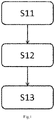
- a method for determining a status of a battery temperature sensor includes the following steps: In step S11, a highest temperature reading and a lowest temperature reading of a temperature sensor that are reported in a stable vehicle working condition are received; in step S12, a highest temperature reading trend, a lowest temperature reading trend, and a largest temperature reading difference in the stable vehicle working condition are determined based on the highest temperature reading and the lowest temperature reading; and in step S13, a status of the temperature sensor is determined based on the highest temperature reading trend, the lowest temperature reading trend, and the largest temperature reading difference.
- reading statistics of the temperature sensor that are collected at intervals of a predetermined time in the stable vehicle working condition are received in step S11, where the reading statistics include a highest temperature reading and a lowest temperature reading of the temperature sensor within each predetermined time.
- the stable working condition may be a single working condition.
- the stable vehicle working condition may be a vehicle driving condition or a vehicle charging condition.
- the stable working condition may be a hybrid working condition.
- the stable working condition includes a low-speed vehicle driving condition and a vehicle slow-charging condition.
- the stable working condition in the invention refers to a single or hybrid working condition that does not cause drastic changes in battery temperature. A specific scenario of the stable working condition may be determined based on experiments or theory.
- the vehicle driving condition is any time period in a process from the start to the end of a vehicle trip
- the vehicle charging condition is any time period in a process from the start to the end of vehicle charging.
- the stable working condition does not need to meet specified duration, provided that the status of the sensor can be determined based on analysis of data in the stable working condition.
- the vehicle driving condition may be any time period in a process from the start to the end of a vehicle trip, or a constant-speed or approximately constant-speed process in the vehicle trip. In a constant-speed cruise process, battery temperature is more stable, which facilitates determining of a status of a sensor.
- a fault may occur when values measured by the sensor change drastically.
- the vehicle charging condition as the stable working condition is any time period in a process from the start to the end of vehicle charging, or may be the end stage of the charging process. This stage is "trickle" charging, and battery temperature is relatively stable, which facilitates determining of a status of a sensor.
- battery temperature may be read at specific time intervals, and the time interval depends on actual requirements or hardware condition limitations.
- readings of the sensor are obtained at intervals of a 5-second predetermined time.
- a sampling time of the sensor may be much less than the 5-second predetermined time. Therefore, statistics of the readings of the sensor (namely, statistics of sampling values) may be specifically collected within this period of time.
- the statistics of the readings include the highest temperature reading and the lowest temperature reading of the temperature sensor within each predetermined time.
- Fig. 5 shows how to receive statistics of readings of a temperature sensor in a predetermined time.
- an interval between moment t0 and moment t1 is 5s; an interval between moment t1 and moment t2 is 5s; and other cases can be deduced by analogy.
- Statistics of readings of the temperature sensor in the time period from t0 to t1 are received at moment t1; statistics of readings of the temperature sensor in the time period from t1 to t2 (including the highest temperature reading and the lowest temperature reading in this time period) are received at moment t2; and other cases can be deduced by analogy.
- the highest temperature reading trend, the lowest temperature reading trend, and the largest temperature reading difference in the stable vehicle working condition are determined based on the highest temperature reading and the lowest temperature reading in step S12. Because the data received in step S11 is reported in a real-time or quasi real-time manner, values in the stable vehicle working condition are accumulated continuously. In step S12, the highest temperature reading trend, the lowest temperature reading trend, and the largest temperature reading difference may be calculated based on the accumulated data. It should be understood that, with the accumulation of received data, calculated values are updated continuously.
- the highest temperature reading trend and the lowest temperature reading trend in the invention are specifically quantitative values, arrays, matrices, or the like that reflect trends of or a correlation between the highest temperature reading and the lowest temperature reading.
- the highest temperature reading trend and the lowest temperature reading trend may be slopes reflecting curves of the highest temperature reading and the lowest temperature reading versus time, respectively. If a difference between the slopes keeps departing (for example, the difference between the slopes is greater than a predetermined value within a period of time), the two trends may be inconsistent.
- the highest temperature reading trend and the lowest temperature reading trend may be a correlation coefficient between the highest temperature reading and the lowest temperature reading. In this case, the highest temperature reading trend and the lowest temperature reading trend may be a same value (namely, the correlation coefficient).
- the status of the temperature sensor is determined based on the highest temperature reading trend, the lowest temperature reading trend, and the largest temperature reading difference in step S13.
- the highest temperature reading trend, the lowest temperature reading trend, and the largest temperature reading difference may be used as indexes for evaluating whether the sensor is anomalous.
- whether the temperature sensor is anomalous is determined based on all of the highest temperature reading trend, the lowest temperature reading trend, and the largest temperature reading difference.
- the status of the sensor may specifically include normal, anomalous, or pending.
- the lowest temperature reading trend, and the largest temperature reading difference indicate that the reading of the sensor is normal, it may be considered that the sensor is in a normal state.
- all of the highest temperature reading trend, the lowest temperature reading trend, and the largest temperature reading difference indicate that the reading of the sensor is improper, it may be considered that the sensor is in an anomalous state.
- it cannot be determined that the sensor is in a normal state or in an anomalous state it may be considered that the sensor is in a pending state.
- To further determine whether the sensor in the pending state is anomalous more data needs to be received for observation.
- the method for determining a status of a battery temperature sensor in this application further includes: determining an accumulated highest temperature reading difference and an accumulated lowest temperature reading difference in the stable vehicle working condition based on the highest temperature readings and the lowest temperature readings in adjacent predetermined times, where the accumulated highest temperature reading difference is a sum of absolute values of differences between the highest temperature readings in the adjacent predetermined times, and the accumulated lowest temperature reading difference is a sum of absolute values of differences between the lowest temperature readings in the adjacent predetermined times.
- the highest temperature reading trend and the lowest temperature reading trend that are determined in step S 12 are reflected by the accumulated highest temperature reading difference and the accumulated lowest temperature reading difference.
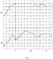
- the upper curve represents a curve of the highest temperature reading versus time
- the lower curve represents a curve of the lowest temperature reading versus time.
- T high , t in which T high denotes a value of the highest temperature reading, and t denotes a moment
- the curve of the highest temperature reading versus time may be represented as follows: (39°C, 1) - (40°C, 2) - (42°C, 3) - (42.5°C, 4) - (43°C, 5) - (43°C, 6) - (43°C, 7) - (43°C, 8) - (43°C, 9) - (43°C, 10) - (43°C, 11) - (42°C, 12) - (42.5°C, 13) - (43°C, 14) - (42°C, 15) - (42°C, 16) - (42°C, 17).
- the curve of the lowest temperature reading versus time may be represented as follows: (29°C, 1) - (30°C, 2) - (31°C, 3) - (33°C, 4) - (31°C, 5) - (32°C, 6) - (33°C, 7) - (34°C, 8) - (33.7°C, 9) - (33.3°C, 10) - (33°C, 11) - (32°C, 12) - (32.5°C, 13) - (33°C, 14) - (33°C, 15) - (33°C, 16) - (32°C, 17).
- the accumulated highest temperature reading difference and the accumulated lowest temperature reading difference reflect fluctuations of the highest temperature reading and the lowest temperature reading over time. Generally, the closer the accumulated highest temperature reading difference and the accumulated lowest temperature reading difference, the closer the fluctuations of the highest temperature reading and the lowest temperature reading, and the closer the trends of the highest temperature reading and the lowest temperature reading may be.
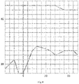
- the upper curve represents a curve of the highest temperature reading versus time
- the lower curve represents a curve of the lowest temperature reading versus time.
- T high , t in which T high denotes a value of the highest temperature reading, and t denotes a moment
- the curve of the highest temperature reading versus time may be represented as follows: (43°C, 1) - (43°C, 2) - (43°C, 3) - (43°C, 4) - (43°C, 5) - (43°C, 6) - (43°C, 7) - (43°C, 8) - (43°C, 9) - (43°C, 10) - (43°C, 11) - (43°C, 12) - (42.5°C, 13) - (42°C, 14) - (42°C, 15) - (42°C, 16) - (42°C, 17).
- the curve of the lowest temperature reading versus time may be represented as follows: (29°C, 1) - (30°C, 2) - (31°C, 3) - (28°C, 4) - (28°C, 5) - (30.5°C, 6) - (33°C, 7) - (34°C, 8) - (33.7°C, 9) - (33.3°C, 10) - (33°C, 11) - (32°C, 12) - (32.5°C, 13) - (33°C, 14) - (33°C, 15) - (33°C, 16) - (32°C, 17).
- the largest temperature reading difference occurs at moment 5, and is 12°C. In an example corresponding to Fig. 4 , the largest temperature reading difference also occurs at moment 5, and is 15°C. If the first preset temperature difference is 10°C, both the foregoing two values meet this condition.
- the temperature sensor may be determined that the temperature sensor is in a normal state.
- N may be 2 is in an example given above based on experience, in some embodiments of this application, N may be determined based on statistics on a battery temperature sensor whose status is known. For example, battery temperature may be measured in a stable working condition based on a battery temperature sensor whose normal state is known; the accumulated highest temperature reading difference and accumulated lowest temperature reading difference are calculated in a manner described above; and a proper value of N may be derived from the differences. It should be noted that different N values may be set for different batches, models, and ages of batteries; and a value of N may be set based on expected, similar, or identical batches, models, and ages of batteries.
- the method for determining a status of a battery temperature sensor in this application further includes: issuing an alarm if it is determined that the temperature sensor is in an anomalous state. If the sensor is anomalous, battery temperature cannot be accurately measured, which causes safety hazards. Therefore, an alarm needs to be issued to prompt drivers, managers and the like when it is determined that the sensor is anomalous.
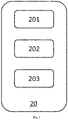
- an apparatus for determining a status of a battery temperature sensor includes a communications module 201, a calculation module 202, and a determining module 203.
- the communications module 201 is configured to receive reading statistics of a temperature sensor that are collected at intervals of a predetermined time in a stable vehicle working condition, where the reading statistics include a highest temperature reading and a lowest temperature reading of the temperature sensor within each predetermined time.
- the invention is mainly focused on temperature sensors of vehicle batteries, the apparatus 20 of the invention is also applicable to temperature sensors in other scenarios.
- the stable working condition may be a single working condition.
- the stable vehicle working condition may be a vehicle driving condition or a vehicle charging condition.
- the stable working condition may be a hybrid working condition.
- the stable working condition includes a low-speed vehicle driving condition and a vehicle slow-charging condition.
- the stable working condition in the invention refers to a single or hybrid working condition that does not cause drastic changes in battery temperature. A specific scenario of the stable working condition may be determined based on experiments or theory.
- the vehicle driving condition is any time period in a process from the start to the end of a vehicle trip
- the vehicle charging condition is any time period in a process from the start to the end of vehicle charging.
- the stable working condition does not need to meet specified duration, provided that the status of the sensor can be determined based on analysis of data in the stable working condition.
- the vehicle driving condition may be any time period in a process from the start to the end of a vehicle trip, or a constant-speed or approximately constant-speed process in the vehicle trip. In a constant-speed cruise process, battery temperature is more stable, which facilitates determining of a status of a sensor.
- a fault may occur when values measured by the sensor change drastically.
- the vehicle charging condition as the stable working condition is any time period in a process from the start to the end of vehicle charging, or may be the end stage of the charging process. This stage is "trickle" charging, and battery temperature is relatively stable, which facilitates determining of a status of a sensor.
- battery temperature may be read at specific time intervals, and the time interval depends on actual requirements or hardware condition limitations.
- readings of the sensor are obtained at intervals of a 5-second predetermined time.
- a sampling time of the sensor may be much less than the 5-second predetermined time. Therefore, statistics of the readings of the sensor (namely, statistics of sampling values) may be specifically collected within this period of time.
- the statistics of the readings include the highest temperature reading and the lowest temperature reading of the temperature sensor within each predetermined time.
- Fig. 5 shows how to receive statistics of readings of a temperature sensor in a predetermined time.
- an interval between moment t0 and moment t1 is 5s; an interval between moment t1 and moment t2 is 5s; and other cases can be deduced by analogy.
- Statistics of readings of the temperature sensor in the time period from t0 to t1 are received at moment t1; statistics of readings of the temperature sensor in the time period from t1 to t2 (including the highest temperature reading and the lowest temperature reading in this time period) are received at moment t2; and other cases can be deduced by analogy.
- the calculation module 202 is configured to determine a highest temperature reading trend, a lowest temperature reading trend, and a largest temperature reading difference in the stable vehicle working condition based on the highest temperature reading and the lowest temperature reading. Because the data received by the communications module 201 is reported in a real-time or quasi real-time manner, values in the stable vehicle working condition are accumulated continuously. The calculation module 202 may calculate the highest temperature reading trend, the lowest temperature reading trend, and the largest temperature reading difference based on the accumulated data. It should be understood that, with the accumulation of received data, calculated values are updated continuously.
- the highest temperature reading trend and the lowest temperature reading trend in the invention are specifically quantitative values, arrays, matrices, or the like that reflect trends of or a correlation between the highest temperature reading and the lowest temperature reading.
- the highest temperature reading trend and the lowest temperature reading trend may be slopes reflecting curves of the highest temperature reading and the lowest temperature reading versus time, respectively. If a difference between the slopes keeps departing (for example, the difference between the slopes is greater than a predetermined value within a period of time), the two trends may be inconsistent.
- the highest temperature reading trend and the lowest temperature reading trend may be a correlation coefficient between the highest temperature reading and the lowest temperature reading. In this case, the highest temperature reading trend and the lowest temperature reading trend may be a same value (namely, the correlation coefficient).
- the determining module 203 is configured to determine a status of the temperature sensor based on the highest temperature reading trend, the lowest temperature reading trend, and the largest temperature reading difference. As described above, the highest temperature reading trend, the lowest temperature reading trend, and the largest temperature reading difference may be used as indexes for evaluating whether the sensor is anomalous. In this application, the determining module 203 determines, based on all of the highest temperature reading trend, the lowest temperature reading trend, and the largest temperature reading difference, whether the temperature sensor is anomalous.
- the status of the sensor may specifically include: normal, anomalous, or pending.
- normal When all of the highest temperature reading trend, the lowest temperature reading trend, and the largest temperature reading difference indicate that the reading of the sensor is normal, it may be considered that the sensor is in a normal state.
- all of the highest temperature reading trend, the lowest temperature reading trend, and the largest temperature reading difference indicate that the reading of the sensor is improper, it may be considered that the sensor is in an anomalous state. In other cases, if it cannot be determined that the sensor is in a normal state or in an anomalous state, it may be considered that the sensor is in a pending state. To further determine whether the sensor in the pending state is anomalous, more data needs to be received for observation.
- the calculation module 202 is configured to calculate an accumulated highest temperature reading difference and an accumulated lowest temperature reading difference in the stable vehicle working condition based on the highest temperature readings and the lowest temperature readings in adjacent predetermined times, where the accumulated highest temperature reading difference is a sum of absolute values of differences between the highest temperature readings in the adjacent predetermined times, and the accumulated lowest temperature reading difference is a sum of absolute values of differences between the lowest temperature readings in the adjacent predetermined times.
- the highest temperature reading trend and the lowest temperature reading trend that are determined by the calculation module 202 in the above are reflected by the accumulated highest temperature reading difference and the accumulated lowest temperature reading difference.
- the determining module 203 is configured to further determine the status of the temperature sensor based on the accumulated highest temperature reading difference, the accumulated lowest temperature reading difference, and the largest temperature reading difference.
- the upper curve represents a curve of the highest temperature reading versus time
- the lower curve represents a curve of the lowest temperature reading versus time.
- T high , t in which T high denotes a value of the highest temperature reading, and t denotes a moment
- the curve of the highest temperature reading versus time may be represented as follows: (39°C, 1) - (40°C, 2) - (42°C, 3) - (42.5°C, 4) - (43°C, 5) - (43°C, 6) - (43°C, 7) - (43°C, 8) - (43°C, 9) - (43°C, 10) - (43°C, 11) - (42°C, 12) - (42.5°C, 13) - (43°C, 14) - (42°C, 15) - (42°C, 16) - (42°C, 17).
- the curve of the lowest temperature reading versus time may be represented as follows: (29°C, 1) - (30°C, 2) - (31°C, 3) - (33°C, 4) - (31°C, 5) - (32°C, 6) - (33°C, 7) - (34°C, 8) - (33.7°C, 9) - (33.3°C, 10) - (33°C, 11) - (32°C, 12) - (32.5°C, 13) - (33°C, 14) - (33°C, 15) - (33°C, 16) - (32°C, 17).
- the accumulated highest temperature reading difference and the accumulated lowest temperature reading difference reflect fluctuations of the highest temperature reading and the lowest temperature reading over time. Generally, the closer the accumulated highest temperature reading difference and the accumulated lowest temperature reading difference, the closer the fluctuations of the highest temperature reading and the lowest temperature reading, and the closer the trends of the highest temperature reading and the lowest temperature reading may be.
- the upper curve represents a curve of the highest temperature reading versus time
- the lower curve represents a curve of the lowest temperature reading versus time.
- T high , t in which T high denotes a value of the highest temperature reading, and t denotes a moment
- the curve of the highest temperature reading versus time may be represented as follows: (43°C, 1) - (43°C, 2) - (43°C, 3) - (43°C, 4) - (43°C, 5) - (43°C, 6) - (43°C, 7) - (43°C, 8) - (43°C, 9) - (43°C, 10) - (43°C, 11) - (43°C, 12) - (42.5°C, 13) - (42°C, 14) - (42°C, 15) - (42°C, 16) - (42°C, 17).
- the curve of the lowest temperature reading versus time may be represented as follows: (29°C, 1) - (30°C, 2) - (31°C, 3) - (28°C, 4) - (28°C, 5) - (30.5°C, 6) - (33°C, 7) - (34°C, 8) - (33.7°C, 9) - (33.3°C, 10) - (33°C, 11) - (32°C, 12) - (32.5°C, 13) - (33°C, 14) - (33°C, 15) - (33°C, 16) - (32°C, 17).
- the largest temperature reading difference occurs at moment 5, and is 12°C. In an example corresponding to Fig. 4 , the largest temperature reading difference also occurs at moment 5, and is 15°C. If the first preset temperature difference is 10°C, the determining module 203 may determine that both the foregoing two values meet this condition.
- the apparatus 20 further includes a statistics collection module (not shown in the figure).
- the statistics collection module is configured to determine a value of N based on statistics on a battery temperature sensor whose status is known. For example, battery temperature may be measured in a stable working condition based on a battery temperature sensor whose normal state is known; the accumulated highest temperature reading difference and accumulated lowest temperature reading difference are calculated in a manner described above; and a proper value of N may be derived from the differences. It should be noted that different N values may be set for different batches, models, and ages of batteries; and a value of N may be set based on expected, similar, or identical batches, models, and ages of batteries. In some examples, the statistics collection module determines a proper value of N based on machine learning, without taking a batch, model, age, and other attributes of a sample battery into consideration.
- the apparatus 20 further includes an alarm module (not shown in the figure).
- the alarm module is configured to issue an alarm when the determining module 203 determines that the temperature sensor is in an anomalous state. If the sensor is anomalous, battery temperature cannot be accurately measured, which causes safety hazards. Therefore, the alarm module may issue an alarm to prompt drivers, managers and the like when it is determined that the sensor is anomalous.
- a vehicle including any one of the foregoing apparatuses for determining a status of a battery temperature sensor.
- the apparatus for determining a status of a battery temperature sensor may be an onboard apparatus, which has a local processing capability and may determine a status of a sensor locally in the vehicle. Preloading such a device on the vehicle endows the vehicle with an offline processing capability. Therefore, the vehicle can determine a status of a sensor by its own hardware.
- a battery management server including any one of the foregoing apparatuses for determining a status of a battery temperature sensor.
- the apparatus for determining a status of a battery temperature sensor may be a cloud device that can be embedded into an existing cloud system (server or array) by a vehicle manufacturer or battery service provider.
- a vehicle periodically uploads battery signal data to cloud in charging and driving processes.
- the cloud system stores the data in a data warehouse for analysis and use.
- the apparatus for determining a status of a battery temperature sensor may determine a status of a sensor based on data that is of the sensor and that is collected by the cloud system.
- a computer-readable storage medium stores instructions, and the instructions, when executed by a processor, cause the processor to perform any one of the foregoing methods for determining a status of a battery temperature sensor.
- the computer-readable storage medium in this application includes various computer storage media, and may be any usable medium accessible to a general-purpose or special-purpose computer.
- the computer-readable storage medium may include a RAM, a ROM, an EPROM, an E 2 PROM, a register, a hard disk, a removable hard disk, a CD-ROM or another optical memory, a magnetic disk memory or another magnetic storage device, or any other transitory or non-transitory media that can carry or store expected program code having an instruction or data structure form and be accessible to the general-purpose or special-purpose computer or a general-purpose or special-purpose processor.
- Data is usually copied magnetically in a disk used in this specification, while data is usually copied optically by using lasers in a disc. A combination thereof shall also fall within the protection scope of computer-readable media.
- the storage medium is coupled to a processor, so that the processor can read data from and write data to the storage medium.
- the storage medium may be integrated into the processor.
- the processor and the storage medium may reside in an ASIC.
- the ASIC may reside in a user terminal.
- the processor and the storage medium may reside as discrete assemblies in a user terminal.
Landscapes
- Engineering & Computer Science (AREA)
- General Physics & Mathematics (AREA)
- Physics & Mathematics (AREA)
- Mechanical Engineering (AREA)
- Sustainable Development (AREA)
- Sustainable Energy (AREA)
- Power Engineering (AREA)
- Transportation (AREA)
- Life Sciences & Earth Sciences (AREA)
- Manufacturing & Machinery (AREA)
- Chemical & Material Sciences (AREA)
- Chemical Kinetics & Catalysis (AREA)
- Electrochemistry (AREA)
- General Chemical & Material Sciences (AREA)
- Secondary Cells (AREA)
- Electric Propulsion And Braking For Vehicles (AREA)
Abstract
Description
- This application relates to the field of vehicle sensors, and specifically, to a method and an apparatus for determining a status of a battery temperature sensor, a computer-readable storage medium, a vehicle, and a battery management server.
- In contrast with the rapid promotion of electric vehicles in recent years, batteries as the heart for traction are frequently face fires, explosions and other problems that seriously affect social security. Temperature is one of the core indexes of batteries. Whether a battery is used in a safe state depends on whether a temperature sensor can work normally. Therefore, finding an anomaly of the sensor in time is of great significance to safe use of the battery.
- Although the temperature sensor has gone through strict reliability tests during production and installation, changes in voltage and temperature may still cause a fault to the sensor. As electric vehicles are an emerging industry, there is currently no good method capable of detecting a battery temperature sensor on an electric vehicle.
- Embodiments of this application provide a method and an apparatus for determining a status of a battery temperature sensor, a computer-readable storage medium, a vehicle, and a battery management server, to accurately determine whether a battery temperature sensor is anomalous, thereby troubleshooting problems in time and eliminating potential safety hazards in use of electric vehicle batteries.
- According to an aspect of this application, a method for determining a status of a battery temperature sensor is provided, including: receiving reading statistics of a temperature sensor that are collected at intervals of a predetermined time in a stable vehicle working condition, where the reading statistics include a highest temperature reading and a lowest temperature reading of the temperature sensor within each predetermined time; determining a highest temperature reading trend, a lowest temperature reading trend, and a largest temperature reading difference in the stable vehicle working condition based on the highest temperature reading and the lowest temperature reading; and determining a status of the temperature sensor based on the highest temperature reading trend, the lowest temperature reading trend, and the largest temperature reading difference.
- In some embodiments of this application, optionally, the predetermined time is 5s.
- In some embodiments of this application, optionally, the stable vehicle working condition is a vehicle driving condition or a vehicle charging condition.
- In some embodiments of this application, optionally, the vehicle driving condition is any time period in a process from the start to the end of a vehicle trip, and the vehicle charging condition is any time period in a process from the start to the end of vehicle charging.
- In some embodiments of this application, optionally, the status includes: normal, anomalous, or pending.
- In some embodiments of this application, optionally, the method includes: determining an accumulated highest temperature reading difference and an accumulated lowest temperature reading difference in the stable vehicle working condition based on the highest temperature readings and the lowest temperature readings in adjacent predetermined times, where the accumulated highest temperature reading difference is a sum of absolute values of differences between the highest temperature readings in the adjacent predetermined times, and the accumulated lowest temperature reading difference is a sum of absolute values of differences between the lowest temperature readings in the adjacent predetermined times.
- In some embodiments of this application, optionally, the method includes: if the accumulated lowest temperature reading difference exceeds N times of the accumulated highest temperature reading difference, and the largest temperature reading difference is greater than a first preset temperature difference, determining that the temperature sensor is anomalous, where N is greater than 1.5.
- In some embodiments of this application, optionally, the method includes: if the accumulated lowest temperature reading difference exceeds N times of the accumulated highest temperature reading difference, or the largest temperature reading difference is greater than a first preset temperature difference, determining that the temperature sensor is pending, where N is greater than 1.5.
- In some embodiments of this application, optionally, N = 2.
- In some embodiments of this application, optionally, N is determined based on statistics on a battery temperature sensor whose status is known.
- In some embodiments of this application, optionally, the method includes: issuing an alarm if it is determined that the temperature sensor is in an anomalous state.
- According to another aspect of this application, a computer-readable storage medium is provided, where the computer-readable storage medium stores instructions, and the instructions, when executed by a processor, cause the processor to perform any one of the foregoing methods.
- According to another aspect of this application, an apparatus for determining a status of a battery temperature sensor is provided, including: a communications module configured to receive reading statistics of a temperature sensor that are collected at intervals of a predetermined time in a stable vehicle working condition, where the reading statistics include a highest temperature reading and a lowest temperature reading of the temperature sensor within each predetermined time; a calculation module configured to determine a highest temperature reading trend, a lowest temperature reading trend, and a largest temperature reading difference in the stable vehicle working condition based on the highest temperature reading and the lowest temperature reading; and a determining module configured to determine a status of the temperature sensor based on the highest temperature reading trend, the lowest temperature reading trend, and the largest temperature reading difference.
- In some embodiments of this application, optionally, the predetermined time is 5s.
- In some embodiments of this application, optionally, the stable vehicle working condition is a vehicle driving condition or a vehicle charging condition.
- In some embodiments of this application, optionally, the vehicle driving condition is any time period in a process from the start to the end of a vehicle trip, and the vehicle charging condition is any time period in a process from the start to the end of vehicle charging.
- In some embodiments of this application, optionally, the status includes: normal, anomalous, or pending.
- In some embodiments of this application, optionally, the calculation module is configured to determine an accumulated highest temperature reading difference and an accumulated lowest temperature reading difference in the stable vehicle working condition based on the highest temperature readings and the lowest temperature readings in adjacent predetermined times, where the accumulated highest temperature reading difference is a sum of absolute values of differences between the highest temperature readings in the adjacent predetermined times, and the accumulated lowest temperature reading difference is a sum of absolute values of differences between the lowest temperature readings in the adjacent predetermined times; and the determining module is configured to determine the status of the temperature sensor based on the accumulated highest temperature reading difference, the accumulated lowest temperature reading difference, and the largest temperature reading difference.
- In some embodiments of this application, optionally, if the determining module determines that the accumulated lowest temperature reading difference exceeds N times of the accumulated highest temperature reading difference, and the largest temperature reading difference is greater than a first preset temperature difference, the determining module determines that the temperature sensor is anomalous, where N is greater than 1.5.
- In some embodiments of this application, optionally, if the determining module determines that the accumulated lowest temperature reading difference exceeds N times of the accumulated highest temperature reading difference, or the largest temperature reading difference is greater than a first preset temperature difference, the determining module determines that the temperature sensor is pending, where N is greater than 1.5.
- In some embodiments of this application, optionally, N = 2.
- In some embodiments of this application, optionally, the apparatus further includes a statistics collection module configured to determine a value of N based on statistics on a battery temperature sensor whose status is known.
- In some embodiments of this application, optionally, the apparatus further includes an alarm module configured to issue an alarm when the determining module determines that the temperature sensor is in an anomalous state.
- According to another aspect of this application, a vehicle is provided, including any one of the foregoing apparatuses for determining a status of a battery temperature sensor.
- According to another aspect of this application, a battery management server is provided, including any one of the foregoing apparatuses for determining a status of a battery temperature sensor.
- The above and other objectives and advantages of this application will be more thorough and clearer from the following detailed description in conjunction with the drawings, where the same or similar elements are represented by the same reference numerals.
-
Fig. 1 shows a method for determining a status of a battery temperature sensor according to an embodiment of this application; -
Fig. 2 shows an apparatus for determining a status of a battery temperature sensor according to an embodiment of this application; -
Fig. 3 shows a schematic diagram of a principle for determining a status of a battery temperature sensor according to an embodiment of this application; -
Fig. 4 shows a schematic diagram of a principle for determining a status of a battery temperature sensor according to an embodiment of this application; and -
Fig. 5 shows a schematic diagram of a principle for determining a status of a battery temperature sensor according to an embodiment of this application. - For the sake of brevity and illustrative purposes, the principles of this application are mainly described herein with reference to its exemplary embodiments. However, persons skilled in the art can easily appreciate that the same principle can be equivalently applied to all types of methods and apparatuses for determining a status of a battery temperature sensor, computer-readable storage media, vehicles, and battery management servers, and a same or similar principle can be implemented. These variations do not depart from the true spirit and scope of this application.
- The following embodiments are to provide a mechanism for determining a sensor fault based on battery highest and lowest temperature trends, and a temperature difference. This mechanism is capable of determining a status of a sensor nearly in real time.
- Statistics of received readings are recorded in this application. However, in some cases, a sensor does not need to collect actual statistics on data, but send only actually collected temperature readings (at sampling moments). In this case, a receiving side may include a step/module for collecting statistics on the data at predetermined intervals in advance. It may be considered that the statistics of received readings recorded herein are from the step/module.
- According to an aspect of this application, a method for determining a status of a battery temperature sensor is provided. As shown in
Fig. 1 , the method includes the following steps: In step S11, a highest temperature reading and a lowest temperature reading of a temperature sensor that are reported in a stable vehicle working condition are received; in step S12, a highest temperature reading trend, a lowest temperature reading trend, and a largest temperature reading difference in the stable vehicle working condition are determined based on the highest temperature reading and the lowest temperature reading; and in step S13, a status of the temperature sensor is determined based on the highest temperature reading trend, the lowest temperature reading trend, and the largest temperature reading difference. - According to the method for determining a status of a battery temperature sensor, reading statistics of the temperature sensor that are collected at intervals of a predetermined time in the stable vehicle working condition are received in step S11, where the reading statistics include a highest temperature reading and a lowest temperature reading of the temperature sensor within each predetermined time. Although the invention is mainly focused on temperature sensors of vehicle batteries, the basic principle of the invention is also applicable to temperature sensors in other scenarios.
- Temperature changes of a battery may be inconsistent in an unstable working condition, which affects a reading change trend of a sensor. Therefore, performance of the sensor when the vehicle is in a stable working condition may be used to evaluate whether the sensor works normally. As an example, the stable working condition may be a single working condition. In some embodiments of this application, the stable vehicle working condition may be a vehicle driving condition or a vehicle charging condition. In other examples, the stable working condition may be a hybrid working condition. For example, the stable working condition includes a low-speed vehicle driving condition and a vehicle slow-charging condition. The stable working condition in the invention refers to a single or hybrid working condition that does not cause drastic changes in battery temperature. A specific scenario of the stable working condition may be determined based on experiments or theory.
- In some embodiments of this application, the vehicle driving condition is any time period in a process from the start to the end of a vehicle trip, and the vehicle charging condition is any time period in a process from the start to the end of vehicle charging. In this application, the stable working condition does not need to meet specified duration, provided that the status of the sensor can be determined based on analysis of data in the stable working condition. In a case that the stable working condition is a single working condition, the vehicle driving condition may be any time period in a process from the start to the end of a vehicle trip, or a constant-speed or approximately constant-speed process in the vehicle trip. In a constant-speed cruise process, battery temperature is more stable, which facilitates determining of a status of a sensor. A fault may occur when values measured by the sensor change drastically. In addition, the vehicle charging condition as the stable working condition is any time period in a process from the start to the end of vehicle charging, or may be the end stage of the charging process. This stage is "trickle" charging, and battery temperature is relatively stable, which facilitates determining of a status of a sensor.
- Generally, battery temperature may be read at specific time intervals, and the time interval depends on actual requirements or hardware condition limitations. In some embodiments of this application, readings of the sensor are obtained at intervals of a 5-second predetermined time. A sampling time of the sensor may be much less than the 5-second predetermined time. Therefore, statistics of the readings of the sensor (namely, statistics of sampling values) may be specifically collected within this period of time. The statistics of the readings include the highest temperature reading and the lowest temperature reading of the temperature sensor within each predetermined time.
Fig. 5 shows how to receive statistics of readings of a temperature sensor in a predetermined time. As shown in the figure, an interval between moment t0 and moment t1 is 5s; an interval between moment t1 and moment t2 is 5s; and other cases can be deduced by analogy. Statistics of readings of the temperature sensor in the time period from t0 to t1 (including the highest temperature reading and the lowest temperature reading in this time period) are received at moment t1; statistics of readings of the temperature sensor in the time period from t1 to t2 (including the highest temperature reading and the lowest temperature reading in this time period) are received at moment t2; and other cases can be deduced by analogy. - According to the method for determining a status of a battery temperature sensor, the highest temperature reading trend, the lowest temperature reading trend, and the largest temperature reading difference in the stable vehicle working condition are determined based on the highest temperature reading and the lowest temperature reading in step S12. Because the data received in step S11 is reported in a real-time or quasi real-time manner, values in the stable vehicle working condition are accumulated continuously. In step S12, the highest temperature reading trend, the lowest temperature reading trend, and the largest temperature reading difference may be calculated based on the accumulated data. It should be understood that, with the accumulation of received data, calculated values are updated continuously.
- The highest temperature reading trend and the lowest temperature reading trend in the invention are specifically quantitative values, arrays, matrices, or the like that reflect trends of or a correlation between the highest temperature reading and the lowest temperature reading. For example, the highest temperature reading trend and the lowest temperature reading trend may be slopes reflecting curves of the highest temperature reading and the lowest temperature reading versus time, respectively. If a difference between the slopes keeps departing (for example, the difference between the slopes is greater than a predetermined value within a period of time), the two trends may be inconsistent. For another example, the highest temperature reading trend and the lowest temperature reading trend may be a correlation coefficient between the highest temperature reading and the lowest temperature reading. In this case, the highest temperature reading trend and the lowest temperature reading trend may be a same value (namely, the correlation coefficient).
- In addition, the invention is also focused on the largest temperature reading difference in the stable vehicle working condition. Still referring to
Fig. 5 , if the highest temperature reading between moment t0 and moment t1 is TH0, and the lowest temperature reading is TL0, a temperature reading difference in this period of time is D0 = TH0 - TL0; if the highest temperature reading between moment t1 and moment t2 is TH1 and the lowest temperature reading is TL1, a temperature reading difference in this period of time is D1 = TH1 - TL1; and other cases can be deduced by analogy. Finally, values of D0, D1, ... are compared, and the largest value is used as the largest temperature reading difference in the stable vehicle working condition. The largest temperature reading difference may also be used as an index reflecting whether the sensor is anomalous. - According to the method for determining a status of a battery temperature sensor, the status of the temperature sensor is determined based on the highest temperature reading trend, the lowest temperature reading trend, and the largest temperature reading difference in step S13. As described above, the highest temperature reading trend, the lowest temperature reading trend, and the largest temperature reading difference may be used as indexes for evaluating whether the sensor is anomalous. In this application, whether the temperature sensor is anomalous is determined based on all of the highest temperature reading trend, the lowest temperature reading trend, and the largest temperature reading difference.
- In some embodiments of this application, the status of the sensor may specifically include normal, anomalous, or pending. When all of the highest temperature reading trend, the lowest temperature reading trend, and the largest temperature reading difference indicate that the reading of the sensor is normal, it may be considered that the sensor is in a normal state. When all of the highest temperature reading trend, the lowest temperature reading trend, and the largest temperature reading difference indicate that the reading of the sensor is improper, it may be considered that the sensor is in an anomalous state. In other cases, if it cannot be determined that the sensor is in a normal state or in an anomalous state, it may be considered that the sensor is in a pending state. To further determine whether the sensor in the pending state is anomalous, more data needs to be received for observation.
- In some embodiments of this application, the method for determining a status of a battery temperature sensor in this application further includes: determining an accumulated highest temperature reading difference and an accumulated lowest temperature reading difference in the stable vehicle working condition based on the highest temperature readings and the lowest temperature readings in adjacent predetermined times, where the accumulated highest temperature reading difference is a sum of absolute values of differences between the highest temperature readings in the adjacent predetermined times, and the accumulated lowest temperature reading difference is a sum of absolute values of differences between the lowest temperature readings in the adjacent predetermined times. In this case, the highest temperature reading trend and the lowest temperature reading trend that are determined in step S 12 are reflected by the accumulated highest temperature reading difference and the accumulated lowest temperature reading difference.
- As shown in
Fig. 3 , the upper curve represents a curve of the highest temperature reading versus time, and the lower curve represents a curve of the lowest temperature reading versus time. If (Thigh, t) (in which Thigh denotes a value of the highest temperature reading, and t denotes a moment) is used to represent values at points in the graph, the curve of the highest temperature reading versus time may be represented as follows:
(39°C, 1) - (40°C, 2) - (42°C, 3) - (42.5°C, 4) - (43°C, 5) - (43°C, 6) - (43°C, 7) - (43°C, 8) - (43°C, 9) - (43°C, 10) - (43°C, 11) - (42°C, 12) - (42.5°C, 13) - (43°C, 14) - (42°C, 15) - (42°C, 16) - (42°C, 17). At this time (moment 17), the accumulated highest temperature reading difference is:
- If (Tlow, t) (in which Tlow denotes a value of the lowest temperature reading, and t denotes a moment) is used to represent values at points in the graph, the curve of the lowest temperature reading versus time may be represented as follows:
(29°C, 1) - (30°C, 2) - (31°C, 3) - (33°C, 4) - (31°C, 5) - (32°C, 6) - (33°C, 7) - (34°C, 8) - (33.7°C, 9) - (33.3°C, 10) - (33°C, 11) - (32°C, 12) - (32.5°C, 13) - (33°C, 14) - (33°C, 15) - (33°C, 16) - (32°C, 17). At this time (moment 17), the accumulated lowest temperature reading difference is:
- The accumulated highest temperature reading difference and the accumulated lowest temperature reading difference reflect fluctuations of the highest temperature reading and the lowest temperature reading over time. Generally, the closer the accumulated highest temperature reading difference and the accumulated lowest temperature reading difference, the closer the fluctuations of the highest temperature reading and the lowest temperature reading, and the closer the trends of the highest temperature reading and the lowest temperature reading may be.
- In some embodiments of this application, the method for determining a status of a battery temperature sensor in this application further includes: if the accumulated lowest temperature reading difference exceeds N times of the accumulated highest temperature reading difference, and the largest temperature reading difference is greater than a first preset temperature difference, determining that the temperature sensor is anomalous, where N is greater than 1.5 (for example, N = 2).
- Turning to
Fig. 4 , the upper curve represents a curve of the highest temperature reading versus time, and the lower curve represents a curve of the lowest temperature reading versus time. If (Thigh, t) (in which Thigh denotes a value of the highest temperature reading, and t denotes a moment) is used to represent values at points in the graph, the curve of the highest temperature reading versus time may be represented as follows:
(43°C, 1) - (43°C, 2) - (43°C, 3) - (43°C, 4) - (43°C, 5) - (43°C, 6) - (43°C, 7) - (43°C, 8) - (43°C, 9) - (43°C, 10) - (43°C, 11) - (43°C, 12) - (42.5°C, 13) - (42°C, 14) - (42°C, 15) - (42°C, 16) - (42°C, 17). At this time (moment 17), the accumulated highest temperature reading difference is:
- If (Tlow, t) (in which Tlow denotes a value of the lowest temperature reading, and t denotes a moment) is used to represent values at points in the graph, the curve of the lowest temperature reading versus time may be represented as follows:
(29°C, 1) - (30°C, 2) - (31°C, 3) - (28°C, 4) - (28°C, 5) - (30.5°C, 6) - (33°C, 7) - (34°C, 8) - (33.7°C, 9) - (33.3°C, 10) - (33°C, 11) - (32°C, 12) - (32.5°C, 13) - (33°C, 14) - (33°C, 15) - (33°C, 16) - (32°C, 17). At this time (moment 17), the accumulated lowest temperature reading difference is:
- In this case, 15°C > 1°C * 2, and the condition that the accumulated lowest temperature reading difference exceeds N times of the accumulated highest temperature reading difference (N = 2) is met. In an example corresponding to
Fig. 3 , 13°C < 7°C * 2, and the condition that the accumulated lowest temperature reading difference exceeds N times of the accumulated highest temperature reading difference (N = 2) is not met. - In the example corresponding to
Fig. 3 , the largest temperature reading difference occurs atmoment 5, and is 12°C. In an example corresponding toFig. 4 , the largest temperature reading difference also occurs atmoment 5, and is 15°C. If the first preset temperature difference is 10°C, both the foregoing two values meet this condition. - The example corresponding to
Fig. 4 meets both the following conditions: (1) the accumulated lowest temperature reading difference exceeds N times of the accumulated highest temperature reading difference (N = 2); and (2) the largest temperature reading difference is greater than the firstpreset temperature difference 10°C. In this case, it may be determined that the temperature sensor is in an anomalous state. - In some embodiments of this application, the method for determining a status of a battery temperature sensor in this application further includes: if the accumulated lowest temperature reading difference exceeds N times of the accumulated highest temperature reading difference, or the largest temperature reading difference is greater than a first preset temperature difference, determining that the temperature sensor is pending, where N is greater than 1.5 (for example, N = 2).
- The example corresponding to
Fig. 3 does not meet condition (1) that the accumulated lowest temperature reading difference exceeds N times of the accumulated highest temperature reading difference (N = 2), but meets condition (2) that the largest temperature reading difference is greater than the firstpreset temperature difference 10°C. In this case, it may be determined that the temperature sensor is in a pending state. - In other examples, if the accumulated lowest temperature reading difference is less than N times of the accumulated highest temperature reading difference (N = 1.4), and the largest temperature reading difference is less than the first preset temperature difference (for example, 7°C), it may be determined that the temperature sensor is in a normal state.
- Although N may be 2 is in an example given above based on experience, in some embodiments of this application, N may be determined based on statistics on a battery temperature sensor whose status is known. For example, battery temperature may be measured in a stable working condition based on a battery temperature sensor whose normal state is known; the accumulated highest temperature reading difference and accumulated lowest temperature reading difference are calculated in a manner described above; and a proper value of N may be derived from the differences. It should be noted that different N values may be set for different batches, models, and ages of batteries; and a value of N may be set based on expected, similar, or identical batches, models, and ages of batteries.
- In some embodiments of this application, the method for determining a status of a battery temperature sensor in this application further includes: issuing an alarm if it is determined that the temperature sensor is in an anomalous state. If the sensor is anomalous, battery temperature cannot be accurately measured, which causes safety hazards. Therefore, an alarm needs to be issued to prompt drivers, managers and the like when it is determined that the sensor is anomalous.
- According to another aspect of this application, an apparatus for determining a status of a battery temperature sensor is provided. As shown in
Fig.2 , theapparatus 20 includes acommunications module 201, acalculation module 202, and a determiningmodule 203. Thecommunications module 201 is configured to receive reading statistics of a temperature sensor that are collected at intervals of a predetermined time in a stable vehicle working condition, where the reading statistics include a highest temperature reading and a lowest temperature reading of the temperature sensor within each predetermined time. Although the invention is mainly focused on temperature sensors of vehicle batteries, theapparatus 20 of the invention is also applicable to temperature sensors in other scenarios. - Temperature changes of a battery may be inconsistent in an unstable working condition, which affects a reading change trend of a sensor. Therefore, performance of the sensor when the vehicle is in a stable working condition may be used to evaluate whether the sensor works normally. As an example, the stable working condition may be a single working condition. In some embodiments of this application, the stable vehicle working condition may be a vehicle driving condition or a vehicle charging condition. In other examples, the stable working condition may be a hybrid working condition. For example, the stable working condition includes a low-speed vehicle driving condition and a vehicle slow-charging condition. The stable working condition in the invention refers to a single or hybrid working condition that does not cause drastic changes in battery temperature. A specific scenario of the stable working condition may be determined based on experiments or theory.
- In some embodiments of this application, the vehicle driving condition is any time period in a process from the start to the end of a vehicle trip, and the vehicle charging condition is any time period in a process from the start to the end of vehicle charging. In this application, the stable working condition does not need to meet specified duration, provided that the status of the sensor can be determined based on analysis of data in the stable working condition. In a case that the stable working condition is a single working condition, the vehicle driving condition may be any time period in a process from the start to the end of a vehicle trip, or a constant-speed or approximately constant-speed process in the vehicle trip. In a constant-speed cruise process, battery temperature is more stable, which facilitates determining of a status of a sensor. A fault may occur when values measured by the sensor change drastically. In addition, the vehicle charging condition as the stable working condition is any time period in a process from the start to the end of vehicle charging, or may be the end stage of the charging process. This stage is "trickle" charging, and battery temperature is relatively stable, which facilitates determining of a status of a sensor.
- Generally, battery temperature may be read at specific time intervals, and the time interval depends on actual requirements or hardware condition limitations. In some embodiments of this application, readings of the sensor are obtained at intervals of a 5-second predetermined time. A sampling time of the sensor may be much less than the 5-second predetermined time. Therefore, statistics of the readings of the sensor (namely, statistics of sampling values) may be specifically collected within this period of time. The statistics of the readings include the highest temperature reading and the lowest temperature reading of the temperature sensor within each predetermined time.
Fig. 5 shows how to receive statistics of readings of a temperature sensor in a predetermined time. As shown in the figure, an interval between moment t0 and moment t1 is 5s; an interval between moment t1 and moment t2 is 5s; and other cases can be deduced by analogy. Statistics of readings of the temperature sensor in the time period from t0 to t1 (including the highest temperature reading and the lowest temperature reading in this time period) are received at moment t1; statistics of readings of the temperature sensor in the time period from t1 to t2 (including the highest temperature reading and the lowest temperature reading in this time period) are received at moment t2; and other cases can be deduced by analogy. - The
calculation module 202 is configured to determine a highest temperature reading trend, a lowest temperature reading trend, and a largest temperature reading difference in the stable vehicle working condition based on the highest temperature reading and the lowest temperature reading. Because the data received by thecommunications module 201 is reported in a real-time or quasi real-time manner, values in the stable vehicle working condition are accumulated continuously. Thecalculation module 202 may calculate the highest temperature reading trend, the lowest temperature reading trend, and the largest temperature reading difference based on the accumulated data. It should be understood that, with the accumulation of received data, calculated values are updated continuously. - The highest temperature reading trend and the lowest temperature reading trend in the invention are specifically quantitative values, arrays, matrices, or the like that reflect trends of or a correlation between the highest temperature reading and the lowest temperature reading. For example, the highest temperature reading trend and the lowest temperature reading trend may be slopes reflecting curves of the highest temperature reading and the lowest temperature reading versus time, respectively. If a difference between the slopes keeps departing (for example, the difference between the slopes is greater than a predetermined value within a period of time), the two trends may be inconsistent. For another example, the highest temperature reading trend and the lowest temperature reading trend may be a correlation coefficient between the highest temperature reading and the lowest temperature reading. In this case, the highest temperature reading trend and the lowest temperature reading trend may be a same value (namely, the correlation coefficient).
- In addition, the invention is also focused on the largest temperature reading difference in the stable vehicle working condition. Still referring to
Fig. 5 , if the highest temperature reading between moment t0 and moment t1 is TH0, and the lowest temperature reading is TL0, a temperature reading difference in this period of time is D0 = TH0 - TL0; if the highest temperature reading between moment t1 and moment t2 is TH1 and the lowest temperature reading is TL1, a temperature reading difference in this period of time is D1 = TH1 - TL1; and other cases can be deduced by analogy. Finally, values of D0, D1, ... are compared, and the largest value is used as the largest temperature reading difference in the stable vehicle working condition. The largest temperature reading difference may also be used as an index reflecting whether the sensor is anomalous. - The determining
module 203 is configured to determine a status of the temperature sensor based on the highest temperature reading trend, the lowest temperature reading trend, and the largest temperature reading difference. As described above, the highest temperature reading trend, the lowest temperature reading trend, and the largest temperature reading difference may be used as indexes for evaluating whether the sensor is anomalous. In this application, the determiningmodule 203 determines, based on all of the highest temperature reading trend, the lowest temperature reading trend, and the largest temperature reading difference, whether the temperature sensor is anomalous. - In some embodiments of this application, the status of the sensor may specifically include: normal, anomalous, or pending. When all of the highest temperature reading trend, the lowest temperature reading trend, and the largest temperature reading difference indicate that the reading of the sensor is normal, it may be considered that the sensor is in a normal state. When all of the highest temperature reading trend, the lowest temperature reading trend, and the largest temperature reading difference indicate that the reading of the sensor is improper, it may be considered that the sensor is in an anomalous state. In other cases, if it cannot be determined that the sensor is in a normal state or in an anomalous state, it may be considered that the sensor is in a pending state. To further determine whether the sensor in the pending state is anomalous, more data needs to be received for observation.
- In some embodiments of this application, the
calculation module 202 is configured to calculate an accumulated highest temperature reading difference and an accumulated lowest temperature reading difference in the stable vehicle working condition based on the highest temperature readings and the lowest temperature readings in adjacent predetermined times, where the accumulated highest temperature reading difference is a sum of absolute values of differences between the highest temperature readings in the adjacent predetermined times, and the accumulated lowest temperature reading difference is a sum of absolute values of differences between the lowest temperature readings in the adjacent predetermined times. In this case, the highest temperature reading trend and the lowest temperature reading trend that are determined by thecalculation module 202 in the above are reflected by the accumulated highest temperature reading difference and the accumulated lowest temperature reading difference. The determiningmodule 203 is configured to further determine the status of the temperature sensor based on the accumulated highest temperature reading difference, the accumulated lowest temperature reading difference, and the largest temperature reading difference. - As shown in
Fig. 3 , the upper curve represents a curve of the highest temperature reading versus time, and the lower curve represents a curve of the lowest temperature reading versus time. If (Thigh, t) (in which Thigh denotes a value of the highest temperature reading, and t denotes a moment) is used to represent values at points in the graph, the curve of the highest temperature reading versus time may be represented as follows:
(39°C, 1) - (40°C, 2) - (42°C, 3) - (42.5°C, 4) - (43°C, 5) - (43°C, 6) - (43°C, 7) - (43°C, 8) - (43°C, 9) - (43°C, 10) - (43°C, 11) - (42°C, 12) - (42.5°C, 13) - (43°C, 14) - (42°C, 15) - (42°C, 16) - (42°C, 17). At this time (moment 17), thecalculation module 202 may determine that the accumulated highest temperature reading difference is:
- If (Tlow, t) (in which Tiow denotes a value of the lowest temperature reading, and t denotes a moment) is used to represent values at points in the graph, the curve of the lowest temperature reading versus time may be represented as follows:
(29°C, 1) - (30°C, 2) - (31°C, 3) - (33°C, 4) - (31°C, 5) - (32°C, 6) - (33°C, 7) - (34°C, 8) - (33.7°C, 9) - (33.3°C, 10) - (33°C, 11) - (32°C, 12) - (32.5°C, 13) - (33°C, 14) - (33°C, 15) - (33°C, 16) - (32°C, 17). At this time (moment 17), thecalculation module 202 may determine that the accumulated lowest temperature reading difference is:
- The accumulated highest temperature reading difference and the accumulated lowest temperature reading difference reflect fluctuations of the highest temperature reading and the lowest temperature reading over time. Generally, the closer the accumulated highest temperature reading difference and the accumulated lowest temperature reading difference, the closer the fluctuations of the highest temperature reading and the lowest temperature reading, and the closer the trends of the highest temperature reading and the lowest temperature reading may be.
- In some embodiments of this application, if the determining
module 203 determines that the accumulated lowest temperature reading difference exceeds N times of the accumulated highest temperature reading difference, and the largest temperature reading difference is greater than a first preset temperature difference, the determiningmodule 203 determines that the temperature sensor is anomalous, where N is greater than 1.5 (for example, N = 2). - Turning to
Fig. 4 , the upper curve represents a curve of the highest temperature reading versus time, and the lower curve represents a curve of the lowest temperature reading versus time. If (Thigh, t) (in which Thigh denotes a value of the highest temperature reading, and t denotes a moment) is used to represent values at points in the graph, the curve of the highest temperature reading versus time may be represented as follows:
(43°C, 1) - (43°C, 2) - (43°C, 3) - (43°C, 4) - (43°C, 5) - (43°C, 6) - (43°C, 7) - (43°C, 8) - (43°C, 9) - (43°C, 10) - (43°C, 11) - (43°C, 12) - (42.5°C, 13) - (42°C, 14) - (42°C, 15) - (42°C, 16) - (42°C, 17). At this time (moment 17), thecalculation module 202 may determine that the accumulated highest temperature reading difference is:
- If (Tlow, t) (in which Tlow denotes a value of the lowest temperature reading, and t denotes a moment) is used to represent values at points in the graph, the curve of the lowest temperature reading versus time may be represented as follows:
(29°C, 1) - (30°C, 2) - (31°C, 3) - (28°C, 4) - (28°C, 5) - (30.5°C, 6) - (33°C, 7) - (34°C, 8) - (33.7°C, 9) - (33.3°C, 10) - (33°C, 11) - (32°C, 12) - (32.5°C, 13) - (33°C, 14) - (33°C, 15) - (33°C, 16) - (32°C, 17). At this time (moment 17), thecalculation module 202 may determine that the accumulated lowest temperature reading difference is:
- In this case, 15°C > 1°C * 2, and the determining
module 203 may determine that the condition that the accumulated lowest temperature reading difference exceeds N times of the accumulated highest temperature reading difference (N = 2) is met. In an example corresponding toFig. 3 , 13°C < 7°C * 2, and the determiningmodule 203 may determine that the condition that the condition that the accumulated lowest temperature reading difference exceeds N times of the accumulated highest temperature reading difference (N = 2) is not met. - In the example corresponding to
Fig. 3 , the largest temperature reading difference occurs atmoment 5, and is 12°C. In an example corresponding toFig. 4 , the largest temperature reading difference also occurs atmoment 5, and is 15°C. If the first preset temperature difference is 10°C, the determiningmodule 203 may determine that both the foregoing two values meet this condition. - The determining
module 203 may determine that the example corresponding toFig. 4 meets both the following conditions: (1) the accumulated lowest temperature reading difference exceeds N times of the accumulated highest temperature reading difference (N = 2); and (2) the largest temperature reading difference is greater than the firstpreset temperature difference 10°C. In this case, the determiningmodule 203 may determine that the temperature sensor is in an anomalous state. - In some embodiments of this application, if the determining
module 203 determines that the accumulated lowest temperature reading difference exceeds N times of the accumulated highest temperature reading difference, or the largest temperature reading difference is greater than a first preset temperature difference, the determiningmodule 203 determines that the temperature sensor is pending, where N is greater than 1.5 (for example, N = 2). - The determining
module 203 may determine that the example corresponding toFig. 3 does not meet condition (1) that the accumulated lowest temperature reading difference exceeds N times of the accumulated highest temperature reading difference (N = 2), but meets condition (2) that the largest temperature reading difference is greater than the firstpreset temperature difference 10°C. In this case, the determiningmodule 203 may determine that the temperature sensor is in a pending state. - In other examples, if the determining
module 203 may determine that the accumulated lowest temperature reading difference is less than N times of the accumulated highest temperature reading difference (N = 1.4), and the largest temperature reading difference is less than the first preset temperature difference (for example, 7°C), the determiningmodule 203 may determine that the temperature sensor is in a normal state. - In some embodiments of this application, the
apparatus 20 further includes a statistics collection module (not shown in the figure). The statistics collection module is configured to determine a value of N based on statistics on a battery temperature sensor whose status is known. For example, battery temperature may be measured in a stable working condition based on a battery temperature sensor whose normal state is known; the accumulated highest temperature reading difference and accumulated lowest temperature reading difference are calculated in a manner described above; and a proper value of N may be derived from the differences. It should be noted that different N values may be set for different batches, models, and ages of batteries; and a value of N may be set based on expected, similar, or identical batches, models, and ages of batteries. In some examples, the statistics collection module determines a proper value of N based on machine learning, without taking a batch, model, age, and other attributes of a sample battery into consideration. - In some embodiments of this application, the
apparatus 20 further includes an alarm module (not shown in the figure). The alarm module is configured to issue an alarm when the determiningmodule 203 determines that the temperature sensor is in an anomalous state. If the sensor is anomalous, battery temperature cannot be accurately measured, which causes safety hazards. Therefore, the alarm module may issue an alarm to prompt drivers, managers and the like when it is determined that the sensor is anomalous. - According to another aspect of this application, a vehicle is provided, including any one of the foregoing apparatuses for determining a status of a battery temperature sensor. The apparatus for determining a status of a battery temperature sensor may be an onboard apparatus, which has a local processing capability and may determine a status of a sensor locally in the vehicle. Preloading such a device on the vehicle endows the vehicle with an offline processing capability. Therefore, the vehicle can determine a status of a sensor by its own hardware.
- According to another aspect of this application, a battery management server is provided, including any one of the foregoing apparatuses for determining a status of a battery temperature sensor. The apparatus for determining a status of a battery temperature sensor may be a cloud device that can be embedded into an existing cloud system (server or array) by a vehicle manufacturer or battery service provider. A vehicle periodically uploads battery signal data to cloud in charging and driving processes. The cloud system stores the data in a data warehouse for analysis and use. The apparatus for determining a status of a battery temperature sensor may determine a status of a sensor based on data that is of the sensor and that is collected by the cloud system.
- According to another aspect of this application, a computer-readable storage medium is provided. The computer-readable storage medium stores instructions, and the instructions, when executed by a processor, cause the processor to perform any one of the foregoing methods for determining a status of a battery temperature sensor. The computer-readable storage medium in this application includes various computer storage media, and may be any usable medium accessible to a general-purpose or special-purpose computer. For example, the computer-readable storage medium may include a RAM, a ROM, an EPROM, an E2PROM, a register, a hard disk, a removable hard disk, a CD-ROM or another optical memory, a magnetic disk memory or another magnetic storage device, or any other transitory or non-transitory media that can carry or store expected program code having an instruction or data structure form and be accessible to the general-purpose or special-purpose computer or a general-purpose or special-purpose processor. Data is usually copied magnetically in a disk used in this specification, while data is usually copied optically by using lasers in a disc. A combination thereof shall also fall within the protection scope of computer-readable media. For example, the storage medium is coupled to a processor, so that the processor can read data from and write data to the storage medium. In an alternative solution, the storage medium may be integrated into the processor. The processor and the storage medium may reside in an ASIC. The ASIC may reside in a user terminal. In an alternative solution, the processor and the storage medium may reside as discrete assemblies in a user terminal.
- The foregoing descriptions are merely the embodiments of this application, but are not intended to limit the protection scope of this application. Any feasible variation or replacement figured out by a person skilled in the art within the technical scope disclosed in this application shall fall within the protection scope of this application. In the case of no conflict, the embodiments of this application and features in the embodiments may be combined with each other. The protection scope of this application shall be subject to the protection scope of the claims.
Claims (15)
- A method for determining a status of a battery temperature sensor, comprising:receiving reading statistics of a temperature sensor that are collected at intervals of a predetermined time in a stable vehicle working condition, wherein the reading statistics comprise a highest temperature reading and a lowest temperature reading of the temperature sensor within each predetermined time;determining a highest temperature reading trend, a lowest temperature reading trend, and a largest temperature reading difference in the stable vehicle working condition based on the highest temperature reading and the lowest temperature reading; anddetermining a status of the temperature sensor based on the highest temperature reading trend, the lowest temperature reading trend, and the largest temperature reading difference.
- The method according to claim 1, wherein the stable vehicle working condition is a vehicle driving condition or a vehicle charging condition.
- The method according to claim 1, wherein the method comprises:
determining an accumulated highest temperature reading difference and an accumulated lowest temperature reading difference in the stable vehicle working condition based on the highest temperature readings and the lowest temperature readings in adjacent predetermined times, wherein the accumulated highest temperature reading difference is a sum of absolute values of differences between the highest temperature readings in the adjacent predetermined times, and the accumulated lowest temperature reading difference is a sum of absolute values of differences between the lowest temperature readings in the adjacent predetermined times. - The method according to claim 3, wherein the method comprises: if the accumulated lowest temperature reading difference exceeds N times of the accumulated highest temperature reading difference, and the largest temperature reading difference is greater than a first preset temperature difference, determining that the temperature sensor is anomalous, wherein N is greater than 1.5.
- The method according to claim 3, wherein the method comprises: if the accumulated lowest temperature reading difference exceeds N times of the accumulated highest temperature reading difference, or the largest temperature reading difference is greater than a first preset temperature difference, determining that the temperature sensor is pending, wherein N is greater than 1.5.
- The method according to claim 4 or5, wherein N is determined based on statistics on a battery temperature sensor whose status is known.
- A computer-readable storage medium, wherein the computer-readable storage medium stores instructions, and the instructions, when executed by a processor, cause the processor to perform the method according to any one of claims 1 to 6.
- An apparatus for determining a status of a battery temperature sensor, comprising:a communications module configured to receive reading statistics of a temperature sensor that are collected at intervals of a predetermined time in a stable vehicle working condition, wherein the reading statistics comprise a highest temperature reading and a lowest temperature reading of the temperature sensor within each predetermined time;a calculation module configured to determine a highest temperature reading trend, a lowest temperature reading trend, and a largest temperature reading difference in the stable vehicle working condition based on the highest temperature reading and the lowest temperature reading; anda determining module configured to determine a status of the temperature sensor based on the highest temperature reading trend, the lowest temperature reading trend, and the largest temperature reading difference.
- The apparatus according to claim 8, wherein the stable vehicle working condition is a vehicle driving condition or a vehicle charging condition.
- The apparatus according to claim 8, wherein the calculation module is configured to determine an accumulated highest temperature reading difference and an accumulated lowest temperature reading difference in the stable vehicle working condition based on the highest temperature readings and the lowest temperature readings in adjacent predetermined times, whereinthe accumulated highest temperature reading difference is a sum of absolute values of differences between the highest temperature readings in the adjacent predetermined times, and the accumulated lowest temperature reading difference is a sum of absolute values of differences between the lowest temperature readings in the adjacent predetermined times; andthe determining module is configured to determine the status of the temperature sensor based on the accumulated highest temperature reading difference, the accumulated lowest temperature reading difference, and the largest temperature reading difference.
- The apparatus according to claim 10, wherein if the determining module determines that the accumulated lowest temperature reading difference exceeds N times of the accumulated highest temperature reading difference, and the largest temperature reading difference is greater than a first preset temperature difference, the determining module determines that the temperature sensor is anomalous, wherein N is greater than 1.5.
- The apparatus according to claim 10, wherein if the determining module determines that the accumulated lowest temperature reading difference exceeds N times of the accumulated highest temperature reading difference, or the largest temperature reading difference is greater than a first preset temperature difference, the determining module determines that the temperature sensor is pending, wherein N is greater than 1.5.
- The apparatus according to claim 11 or 12, wherein the apparatus further comprises a statistics collection module configured to determine a value of N based on statistics on a battery temperature sensor whose status is known.
- A vehicle, wherein the vehicle comprises the apparatus for determining a status of a battery temperature sensor according to any one of claims 8 to 13.
- A battery management server, wherein the server comprises the apparatus for determining a status of a battery temperature sensor according to any one of claims 8 to 13 .
Applications Claiming Priority (1)
| Application Number | Priority Date | Filing Date | Title |
|---|---|---|---|
| CN202011145140.XA CN112229543B (en) | 2020-10-23 | 2020-10-23 | Methods, devices, media, vehicles, and servers for determining the status of battery temperature sensors |
Publications (1)
| Publication Number | Publication Date |
|---|---|
| EP3988911A1 true EP3988911A1 (en) | 2022-04-27 |
Family
ID=74110511
Family Applications (1)
| Application Number | Title | Priority Date | Filing Date |
|---|---|---|---|
| EP21204009.1A Pending EP3988911A1 (en) | 2020-10-23 | 2021-10-21 | Method and apparatus for determining status of battery temperature sensor, medium, vehicle, and server |
Country Status (3)
| Country | Link |
|---|---|
| US (1) | US12009490B2 (en) |
| EP (1) | EP3988911A1 (en) |
| CN (1) | CN112229543B (en) |
Cited By (3)
| Publication number | Priority date | Publication date | Assignee | Title |
|---|---|---|---|---|
| CN115730184A (en) * | 2022-09-28 | 2023-03-03 | 重庆长安汽车股份有限公司 | Battery temperature abnormality determination method, device, equipment and storage medium |
| CN116295948A (en) * | 2023-03-17 | 2023-06-23 | 重庆大学 | Abnormal detection method, system and storage medium of industrial temperature sensor in large temperature difference environment |
| EP4726344A1 (en) * | 2024-10-11 | 2026-04-15 | Pratt & Whitney Canada Corp. | Battery management system temperature sensing systems and methods |
Families Citing this family (4)
| Publication number | Priority date | Publication date | Assignee | Title |
|---|---|---|---|---|
| CN115742852B (en) * | 2022-11-17 | 2025-12-16 | 武汉蔚来能源有限公司 | Power battery sampling abnormality identification device, method and power exchange station |
| CN116907682B (en) * | 2023-07-03 | 2026-03-20 | 深圳云基新能源科技有限公司 | A temperature anomaly monitoring system for energy storage power supplies |
| CN117576870B (en) * | 2024-01-15 | 2024-04-09 | 成都车晓科技有限公司 | Vehicle-mounted monitoring battery monitoring system |
| CN118817113A (en) * | 2024-02-29 | 2024-10-22 | 比亚迪股份有限公司 | Temperature sensor detection method, device and terminal equipment |
Citations (4)
| Publication number | Priority date | Publication date | Assignee | Title |
|---|---|---|---|---|
| US20110246105A1 (en) * | 2010-04-05 | 2011-10-06 | Lear Corporation | Method and apparatus for testing at least one temperature sensor in a vehicle |
| US20140376587A1 (en) * | 2012-01-27 | 2014-12-25 | Hino Motors, Ltd. | Abnormality detection apparatus, hybrid vehicle, abnormality detection method, and program |
| US20150132615A1 (en) * | 2013-11-13 | 2015-05-14 | Samsung Sdi Co., Ltd. | Battery pack, apparatus including battery pack, and method of managing battery pack |
| CN105698970A (en) * | 2016-01-29 | 2016-06-22 | 安徽江淮汽车股份有限公司 | Battery pack temperature detection circuit fault diagnosis method |
Family Cites Families (11)
| Publication number | Priority date | Publication date | Assignee | Title |
|---|---|---|---|---|
| JP4105086B2 (en) * | 2003-12-22 | 2008-06-18 | 本田技研工業株式会社 | Temperature sensor failure diagnosis device |
| JP4513426B2 (en) * | 2004-06-15 | 2010-07-28 | トヨタ自動車株式会社 | Temperature sensor abnormality detection method and power supply device |
| DE102004061815A1 (en) * | 2004-12-22 | 2006-07-06 | Robert Bosch Gmbh | Method for monitoring the functionality of a temperature sensor |
| JP2011085477A (en) * | 2009-10-15 | 2011-04-28 | Toyota Motor Corp | Failure decision apparatus of temperature sensor, driving apparatus with the same, and failure decision method of temperature sensor |
| US9500612B2 (en) * | 2013-11-04 | 2016-11-22 | Honeywell International Inc. | Detecting temperature sensor anomalies |
| JP6316656B2 (en) * | 2014-05-22 | 2018-04-25 | 日野自動車株式会社 | Abnormality detection apparatus and abnormality detection method |
| KR101628489B1 (en) * | 2014-09-25 | 2016-06-08 | 현대자동차주식회사 | Apparatus and method for controlling high voltage battery in vehicle |
| JP6428547B2 (en) * | 2015-09-25 | 2018-11-28 | 株式会社デンソー | Temperature detection device |
| US10106142B2 (en) * | 2016-02-11 | 2018-10-23 | GM Global Technology Operations LLC | Method and apparatus to monitor a temperature sensor |
| US10830651B2 (en) * | 2017-06-01 | 2020-11-10 | Nissan North America, Inc. | Thermostat monitoring system and method |
| CN109186813B (en) * | 2018-10-23 | 2020-07-24 | 株洲中车时代电气股份有限公司 | Temperature sensor self-checking device and method |
-
2020
- 2020-10-23 CN CN202011145140.XA patent/CN112229543B/en active Active
-
2021
- 2021-10-21 US US17/507,364 patent/US12009490B2/en active Active
- 2021-10-21 EP EP21204009.1A patent/EP3988911A1/en active Pending
Patent Citations (4)
| Publication number | Priority date | Publication date | Assignee | Title |
|---|---|---|---|---|
| US20110246105A1 (en) * | 2010-04-05 | 2011-10-06 | Lear Corporation | Method and apparatus for testing at least one temperature sensor in a vehicle |
| US20140376587A1 (en) * | 2012-01-27 | 2014-12-25 | Hino Motors, Ltd. | Abnormality detection apparatus, hybrid vehicle, abnormality detection method, and program |
| US20150132615A1 (en) * | 2013-11-13 | 2015-05-14 | Samsung Sdi Co., Ltd. | Battery pack, apparatus including battery pack, and method of managing battery pack |
| CN105698970A (en) * | 2016-01-29 | 2016-06-22 | 安徽江淮汽车股份有限公司 | Battery pack temperature detection circuit fault diagnosis method |
Cited By (3)
| Publication number | Priority date | Publication date | Assignee | Title |
|---|---|---|---|---|
| CN115730184A (en) * | 2022-09-28 | 2023-03-03 | 重庆长安汽车股份有限公司 | Battery temperature abnormality determination method, device, equipment and storage medium |
| CN116295948A (en) * | 2023-03-17 | 2023-06-23 | 重庆大学 | Abnormal detection method, system and storage medium of industrial temperature sensor in large temperature difference environment |
| EP4726344A1 (en) * | 2024-10-11 | 2026-04-15 | Pratt & Whitney Canada Corp. | Battery management system temperature sensing systems and methods |
Also Published As
| Publication number | Publication date |
|---|---|
| CN112229543B (en) | 2026-04-24 |
| US12009490B2 (en) | 2024-06-11 |
| CN112229543A (en) | 2021-01-15 |
| US20220131203A1 (en) | 2022-04-28 |
Similar Documents
| Publication | Publication Date | Title |
|---|---|---|
| US12009490B2 (en) | Method and apparatus for determining status of battery temperature sensor, medium, vehicle, and server | |
| US12461164B2 (en) | Method, system, device and medium for detecting battery state of health | |
| CN110161414B (en) | Power battery thermal runaway online prediction method and system | |
| KR102684286B1 (en) | Battery diagnosis apparatus, battery diagnosis method, battery pack, and vehicle including the same | |
| CN114148216A (en) | Battery self-discharge rate abnormality detection method, system, device and storage medium | |
| US20220026499A1 (en) | Method and System for Monitoring Health Condition of Battery Pack | |
| CN118405025B (en) | A battery management system for fire trucks | |
| CN119805244A (en) | Storage battery medium-long term failure prediction and fault early warning method | |
| WO2026007332A1 (en) | Lithium-plating-risk determination method and apparatus for vehicle-side battery cells, and device, storage medium and product | |
| CN110874693A (en) | Determination method, detection method and device for abnormal working condition of battery pack | |
| CN119827171A (en) | New energy automobile fault diagnosis and early warning system based on artificial intelligence | |
| CN117080624B (en) | Battery heating control method and system | |
| CN116482548A (en) | Method, electronic device and vehicle for monitoring vehicle battery | |
| CN121316643A (en) | A dynamic thermal runaway early warning method and system based on multi-source data fusion | |
| CN121164916A (en) | Inversion method and device for thermal runaway accident of battery | |
| CN120539613A (en) | Battery thermal runaway warning method and device based on voltage feature extraction and dynamic time warping | |
| KR20230168917A (en) | Battery Parameter Estimation Method and Battery Parameter Acquisition Device | |
| CN117192402B (en) | Method, device and medium for detecting conductivity abnormality of new energy equipment | |
| CN121114811B (en) | A method and system for testing the battery performance of intelligent vehicles | |
| CN118395875B (en) | A battery pack health intelligent management method and system | |
| CN117192403A (en) | A method, device and medium for detecting conductive anomalies in new energy equipment | |
| CN114976329B (en) | Method, system and vehicle for processing damaged bottom of battery module in power battery | |
| CN117192404A (en) | A method, device and medium for detecting conductive anomalies in new energy equipment | |
| CN121679400A (en) | Hierarchical early warning method and system for thermal runaway of battery pack | |
| CN120490817A (en) | Battery consistency detection method, system, equipment and storage medium |
Legal Events
| Date | Code | Title | Description |
|---|---|---|---|
| PUAI | Public reference made under article 153(3) epc to a published international application that has entered the european phase |
Free format text: ORIGINAL CODE: 0009012 |
|
| STAA | Information on the status of an ep patent application or granted ep patent |
Free format text: STATUS: THE APPLICATION HAS BEEN PUBLISHED |
|
| AK | Designated contracting states |
Kind code of ref document: A1 Designated state(s): AL AT BE BG CH CY CZ DE DK EE ES FI FR GB GR HR HU IE IS IT LI LT LU LV MC MK MT NL NO PL PT RO RS SE SI SK SM TR |
|
| STAA | Information on the status of an ep patent application or granted ep patent |
Free format text: STATUS: REQUEST FOR EXAMINATION WAS MADE |
|
| 17P | Request for examination filed |
Effective date: 20220712 |
|
| RBV | Designated contracting states (corrected) |
Designated state(s): AL AT BE BG CH CY CZ DE DK EE ES FI FR GB GR HR HU IE IS IT LI LT LU LV MC MK MT NL NO PL PT RO RS SE SI SK SM TR |