EP3988900B1 - Terrain referenced navigation system - Google Patents
Terrain referenced navigation system Download PDFInfo
- Publication number
- EP3988900B1 EP3988900B1 EP20275164.0A EP20275164A EP3988900B1 EP 3988900 B1 EP3988900 B1 EP 3988900B1 EP 20275164 A EP20275164 A EP 20275164A EP 3988900 B1 EP3988900 B1 EP 3988900B1
- Authority
- EP
- European Patent Office
- Prior art keywords
- map
- land
- water
- navigation system
- terrain elevation
- Prior art date
- Legal status (The legal status is an assumption and is not a legal conclusion. Google has not performed a legal analysis and makes no representation as to the accuracy of the status listed.)
- Active
Links
Images



Classifications
-
- G—PHYSICS
- G01—MEASURING; TESTING
- G01C—MEASURING DISTANCES, LEVELS OR BEARINGS; SURVEYING; NAVIGATION; GYROSCOPIC INSTRUMENTS; PHOTOGRAMMETRY OR VIDEOGRAMMETRY
- G01C21/00—Navigation; Navigational instruments not provided for in groups G01C1/00 - G01C19/00
- G01C21/005—Navigation; Navigational instruments not provided for in groups G01C1/00 - G01C19/00 with correlation of navigation data from several sources, e.g. map or contour matching
-
- G—PHYSICS
- G01—MEASURING; TESTING
- G01C—MEASURING DISTANCES, LEVELS OR BEARINGS; SURVEYING; NAVIGATION; GYROSCOPIC INSTRUMENTS; PHOTOGRAMMETRY OR VIDEOGRAMMETRY
- G01C21/00—Navigation; Navigational instruments not provided for in groups G01C1/00 - G01C19/00
- G01C21/38—Electronic maps specially adapted for navigation; Updating thereof
- G01C21/3804—Creation or updating of map data
- G01C21/3807—Creation or updating of map data characterised by the type of data
- G01C21/3826—Terrain data
-
- G—PHYSICS
- G01—MEASURING; TESTING
- G01S—RADIO DIRECTION-FINDING; RADIO NAVIGATION; DETERMINING DISTANCE OR VELOCITY BY USE OF RADIO WAVES; LOCATING OR PRESENCE-DETECTING BY USE OF THE REFLECTION OR RERADIATION OF RADIO WAVES; ANALOGOUS ARRANGEMENTS USING OTHER WAVES
- G01S13/00—Systems using the reflection or reradiation of radio waves, e.g. radar systems; Analogous systems using reflection or reradiation of waves whose nature or wavelength is irrelevant or unspecified
- G01S13/88—Radar or analogous systems specially adapted for specific applications
- G01S13/93—Radar or analogous systems specially adapted for specific applications for anti-collision purposes
- G01S13/931—Radar or analogous systems specially adapted for specific applications for anti-collision purposes of land vehicles
-
- G—PHYSICS
- G01—MEASURING; TESTING
- G01C—MEASURING DISTANCES, LEVELS OR BEARINGS; SURVEYING; NAVIGATION; GYROSCOPIC INSTRUMENTS; PHOTOGRAMMETRY OR VIDEOGRAMMETRY
- G01C21/00—Navigation; Navigational instruments not provided for in groups G01C1/00 - G01C19/00
- G01C21/10—Navigation; Navigational instruments not provided for in groups G01C1/00 - G01C19/00 by using measurements of speed or acceleration
- G01C21/12—Navigation; Navigational instruments not provided for in groups G01C1/00 - G01C19/00 by using measurements of speed or acceleration executed aboard the object being navigated; Dead reckoning
- G01C21/16—Navigation; Navigational instruments not provided for in groups G01C1/00 - G01C19/00 by using measurements of speed or acceleration executed aboard the object being navigated; Dead reckoning by integrating acceleration or speed, i.e. inertial navigation
- G01C21/165—Navigation; Navigational instruments not provided for in groups G01C1/00 - G01C19/00 by using measurements of speed or acceleration executed aboard the object being navigated; Dead reckoning by integrating acceleration or speed, i.e. inertial navigation combined with non-inertial navigation instruments
-
- G—PHYSICS
- G01—MEASURING; TESTING
- G01C—MEASURING DISTANCES, LEVELS OR BEARINGS; SURVEYING; NAVIGATION; GYROSCOPIC INSTRUMENTS; PHOTOGRAMMETRY OR VIDEOGRAMMETRY
- G01C21/00—Navigation; Navigational instruments not provided for in groups G01C1/00 - G01C19/00
- G01C21/20—Instruments for performing navigational calculations
-
- G—PHYSICS
- G01—MEASURING; TESTING
- G01C—MEASURING DISTANCES, LEVELS OR BEARINGS; SURVEYING; NAVIGATION; GYROSCOPIC INSTRUMENTS; PHOTOGRAMMETRY OR VIDEOGRAMMETRY
- G01C21/00—Navigation; Navigational instruments not provided for in groups G01C1/00 - G01C19/00
- G01C21/38—Electronic maps specially adapted for navigation; Updating thereof
- G01C21/3804—Creation or updating of map data
- G01C21/3833—Creation or updating of map data characterised by the source of data
- G01C21/3848—Data obtained from both position sensors and additional sensors
-
- G—PHYSICS
- G01—MEASURING; TESTING
- G01C—MEASURING DISTANCES, LEVELS OR BEARINGS; SURVEYING; NAVIGATION; GYROSCOPIC INSTRUMENTS; PHOTOGRAMMETRY OR VIDEOGRAMMETRY
- G01C21/00—Navigation; Navigational instruments not provided for in groups G01C1/00 - G01C19/00
- G01C21/38—Electronic maps specially adapted for navigation; Updating thereof
- G01C21/3804—Creation or updating of map data
- G01C21/3859—Differential updating map data
-
- G—PHYSICS
- G01—MEASURING; TESTING
- G01C—MEASURING DISTANCES, LEVELS OR BEARINGS; SURVEYING; NAVIGATION; GYROSCOPIC INSTRUMENTS; PHOTOGRAMMETRY OR VIDEOGRAMMETRY
- G01C5/00—Measuring height; Measuring distances transverse to line of sight; Levelling between separated points; Surveyors' levels
- G01C5/005—Measuring height; Measuring distances transverse to line of sight; Levelling between separated points; Surveyors' levels altimeters for aircraft
-
- G—PHYSICS
- G01—MEASURING; TESTING
- G01S—RADIO DIRECTION-FINDING; RADIO NAVIGATION; DETERMINING DISTANCE OR VELOCITY BY USE OF RADIO WAVES; LOCATING OR PRESENCE-DETECTING BY USE OF THE REFLECTION OR RERADIATION OF RADIO WAVES; ANALOGOUS ARRANGEMENTS USING OTHER WAVES
- G01S19/00—Satellite radio beacon positioning systems; Determining position, velocity or attitude using signals transmitted by such systems
- G01S19/38—Determining a navigation solution using signals transmitted by a satellite radio beacon positioning system
- G01S19/39—Determining a navigation solution using signals transmitted by a satellite radio beacon positioning system the satellite radio beacon positioning system transmitting time-stamped messages, e.g. GPS [Global Positioning System], GLONASS [Global Orbiting Navigation Satellite System] or GALILEO
- G01S19/42—Determining position
- G01S19/45—Determining position by combining measurements of signals from the satellite radio beacon positioning system with a supplementary measurement
- G01S19/47—Determining position by combining measurements of signals from the satellite radio beacon positioning system with a supplementary measurement the supplementary measurement being an inertial measurement, e.g. tightly coupled inertial
-
- G—PHYSICS
- G01—MEASURING; TESTING
- G01S—RADIO DIRECTION-FINDING; RADIO NAVIGATION; DETERMINING DISTANCE OR VELOCITY BY USE OF RADIO WAVES; LOCATING OR PRESENCE-DETECTING BY USE OF THE REFLECTION OR RERADIATION OF RADIO WAVES; ANALOGOUS ARRANGEMENTS USING OTHER WAVES
- G01S19/00—Satellite radio beacon positioning systems; Determining position, velocity or attitude using signals transmitted by such systems
- G01S19/38—Determining a navigation solution using signals transmitted by a satellite radio beacon positioning system
- G01S19/39—Determining a navigation solution using signals transmitted by a satellite radio beacon positioning system the satellite radio beacon positioning system transmitting time-stamped messages, e.g. GPS [Global Positioning System], GLONASS [Global Orbiting Navigation Satellite System] or GALILEO
- G01S19/42—Determining position
- G01S19/51—Relative positioning
-
- G—PHYSICS
- G01—MEASURING; TESTING
- G01S—RADIO DIRECTION-FINDING; RADIO NAVIGATION; DETERMINING DISTANCE OR VELOCITY BY USE OF RADIO WAVES; LOCATING OR PRESENCE-DETECTING BY USE OF THE REFLECTION OR RERADIATION OF RADIO WAVES; ANALOGOUS ARRANGEMENTS USING OTHER WAVES
- G01S13/00—Systems using the reflection or reradiation of radio waves, e.g. radar systems; Analogous systems using reflection or reradiation of waves whose nature or wavelength is irrelevant or unspecified
- G01S13/88—Radar or analogous systems specially adapted for specific applications
- G01S13/93—Radar or analogous systems specially adapted for specific applications for anti-collision purposes
- G01S13/931—Radar or analogous systems specially adapted for specific applications for anti-collision purposes of land vehicles
- G01S2013/932—Radar or analogous systems specially adapted for specific applications for anti-collision purposes of land vehicles using own vehicle data, e.g. ground speed, steering wheel direction
Definitions
- TRN Terrain Referenced Navigation
- IRU Inertial Reference Unit
- the navigation solutions often use INS error calibrating Kalman Filters as a means of integrating the navigation solutions provided by the TRN and the INS.
- Position estimates obtained from Inertial Navigation Systems typically drift at a rate of around 2 nautical miles per hour due to the accumulation of errors caused by accelerometers and gyroscopes over time. Navigation systems are able to correct for these errors, to an extent, by using further sources of position estimates, including satellite-based navigation solutions such as GPS, GNSS, etc. However, satellite-based navigation solutions are not reliable: signals can be jammed, spoofed, blocked, etc. which can lead to problems with navigation systems that rely too heavily on these satellite-based navigation solutions. TRN systems offer a further navigation solution that can allow navigation systems to correct for INS errors over time.
- TRN systems utilise Barometric-Inertial mixed altitude and radar altimeters in order to estimate terrain elevation beneath an aircraft. Measured terrain elevation estimates are then correlated with terrain elevation data, stored in a terrain elevation map, along the aircraft's travel path in order to produce a navigation solution - i.e. estimate the position of the aircraft.
- US 5331562 A1 discloses a terrain referenced navigation system utilizing a five-state Kalman filter and a database that utilizes a state variable indicating whether the aircraft is headed over water or land. The accuracy of the filter is improved by ignoring filter coefficients over water.
- this disclosure provides a terrain referenced navigation system comprising: at least one sensor arranged to measure the elevation of terrain below a current position of the navigation system; a terrain elevation map comprising a plurality of map posts that each comprise terrain elevation data; and a land-water detection unit arranged to calculate a proportion of land and/or water of at least a portion of the terrain elevation map based on the terrain elevation data of said portion of said terrain elevation map.
- Terrain maps typically store a fixed elevation for each entry, including entries that correspond to both areas of land and areas of water on the surface of the Earth.
- the elevation of bodies of water rises and falls over time (e.g. as a result of tides, seasonal filling and evaporation of lakes, etc.). This can cause the actual elevation of water to differ from stored elevation values in the terrain map, which can cause errors in position estimates obtained from terrain-referenced navigation systems when such systems try to correlate the measurements of actual height with the stored map heights.
- the effect of inaccurate terrain elevation data over areas of water is particularly problematic over areas of transitions between land and water.
- the measured difference in elevation across the transition can differ from the expected difference in elevation based on the stored elevation values in the terrain elevation map.
- the discrepancy between the actual and expected values may be a number of meters. In practice, this can lead to the TRN outputting inaccurate position estimates and/or state error estimates (e.g. of position, velocity, attitude, etc.), as it may assume that the measured data is correct and therefore fail to correlate the aircraft's position with the correct position on the map (either matching to an incorrect position or making no match at all). This can lead to sharp spikes in navigation error over transitions between land and water.
- the TRN system disclosed herein comprises a land-water detection unit, which provides the ability for the navigation system to estimate a proportion of land and/or water of a portion of the terrain elevation map, using the terrain elevation data stored therein.
- the land-water detection unit allows the navigation system to detect areas of the terrain map that contain transitions between land and water, and allows the TRN system to compensate accordingly when passing over these areas, thereby reducing the effect of these transitions on navigational error.
- the navigation system further comprises: an iterative algorithm unit arranged to determine a position estimate of the navigation system, wherein in each iteration the iterative algorithm unit is arranged to: receive the measured terrain elevation data; receive the proportion of land and/or water of at least a portion of the terrain elevation map from the land-water detection unit; determine whether the current position estimate of the navigation system is over a land-water transition based on the proportion of land and/or water received from the land-water detection unit; and update the position estimate for the next iteration based on the current position estimate, the measured terrain elevation data, the stored terrain elevation data and whether the current position estimate of the navigation system is over a land-water transition.
- Iterative algorithms are often used in navigation systems to take various observations and/or estimates and combine them into an optimal solution. Examples of such iterative algorithms include least squares estimators such as Kalman filters. By taking into account the extra information on the presence of a land-water transition, the iterative algorithm unit can provide an improved estimate of position. In particular, the presence or absence of a land-water transition may be used to change the way in which the other information is combined or processed to form the optimal solution.
- the iterative algorithm unit may be arranged to update the position estimate for the next iteration based on a correlation between measured terrain elevation data and stored terrain elevation data in the terrain elevation map.
- the terrain referenced navigation system further comprises an inertial navigation system (INS), and the iterative algorithm unit is arranged to update the position estimate for the next iteration based further on the signal(s) output by the INS.
- INS inertial navigation system
- This provides additional input that the iterative algorithm unit can take into account when updating the position estimate for the next iteration, allowing the terrain referenced navigation system to produce a more accurate navigation solution.
- the INS can produce a position estimate that is independent of a purely terrain based position estimate.
- the INS produces its position estimate based on integrating the outputs of the IMU (accelerometers and gyros) over time while the purely terrain based position estimate is produced by correlating measurements of the terrain elevation with the stored map of terrain elevation to give a best estimate of current position.
- both of these position estimates may be calculated and combined by the IAU based on inputs from the INS, the stored map of terrain elevation and the terrain elevation sensors. The way in which these two estimates are combined is determined by the iterative algorithm unit which may adjust its optimal solution based on the changes and the reliability of each estimate. Where a land-water transition is detected, the iterative algorithm unit may place less reliance on current measurements as the TRN estimate could be thrown off by an unexpected water level in such areas. Accordingly, the IAU effectively treats the unexpected water level as being of lower significance and does not adjust its optimal position solution so much in response to that unexpected water level.
- the iterative algorithm unit is arranged to update the position estimate for the next iteration based on whether the current position estimate (i.e. the estimate of the previous iteration) is located above a land-water transition by increasing the uncertainty associated with the measured terrain elevation data. In doing so, the iterative algorithm unit effectively assumes that the measured terrain elevation data has a larger error than has been calculated by the normal mechanisms when it is over areas of transition between land and water. This forces the iterative algorithm unit to update the position estimate for the next iteration based more heavily on other sources of navigation (e.g. an INS) when passing over land-water transitions, and thus helps prevent navigation errors caused by discrepancies between measured elevation data and stored elevation data of areas of water.
- INS sources of navigation
- any discrepancy between the measured data and the stored map data is more likely to be within the expected uncertainty and is therefore less likely to cause errors within the iterative algorithm unit.
- the iterative algorithm is more likely to remain convergent in such circumstances.
- the iterative algorithm unit comprises a Kalman filter.
- the iterative algorithm unit may be arranged to de-weight the measured terrain elevation data by increasing the modelled uncertainty of its knowledge of a height state (also known to those skilled in the art as a "Q"-boost) of the iterative algorithm unit when the iterative algorithm unit determines that the navigation system is located above a land-water transition.
- Iterative algorithm units such as Kalman filters, typically utilise a "P"-matrix which holds the covariances of the error estimates of each available system state variable.
- the state vector may include one or more height error states, with their associated entries in the P and Q matrices.
- the height states are therefore associated with the measured terrain elevation data as this is calculated based on height measurements taken by at least one sensor of the navigation system.
- the iterative algorithm unit increases the uncertainty associated with (or reduces the weight of) the measurements associated with the height state (i.e. the measured terrain elevation data) when updating the position estimate for the next iteration.
- weights or de-weighting
- the various pieces of information may be combined together with weighting coefficients that indicate their respective importance or accuracy.
- One way to do this is to weight the measurements according to their estimated uncertainties, with more uncertain measurements given less weight than those with lower uncertainties.
- the iterative algorithm unit is arranged to apply a Q-boost equal to a predetermined amount to the height state of the iterative algorithm unit when it determines that the navigation system is located above a land-water transition.
- the predetermined value may be greater than (0.5 m) 2 , preferably greater than (1 m) 2 , more preferably greater than (2 m) 2 , yet more preferably greater than (3 m) 2 .
- the iterative algorithm unit is arranged to apply a Q-boost equal to an amount dynamically determined by the iterative algorithm based on other variables.
- variables may include local gradients, tide times, flight phase, etc.
- the portion of the terrain elevation map for which the land-water detection unit calculates a proportion of land or water comprises a number of map posts (i.e. individual location data points) corresponding to an area surrounding (and optionally centred on) the current estimated position of the navigation system.
- the size and shape of the area for which the land-water detection unit calculates a proportion of land or water, and therefore the corresponding number of map posts, may depend upon the uncertainty in the current position estimate.
- the portion of the terrain elevation map for which the land-water detection unit calculates a proportion of land or water may comprise a subset of a larger cache comprising a predetermined number of map posts corresponding to an area surrounding the current position estimate.
- the land-water detection unit is arranged to classify a map post as probably land or probably water of at least a portion of the terrain elevation map that may comprise an area of less than 40000 (e.g. 200 by 200) map posts, preferably an area of less than 10000 (e.g. 100 by 100) map posts, more preferably an area of less than 2500 (e.g. 50 by 50) map posts, yet more preferably an area of less than or equal to 1000 (e.g. 30 by 30) map posts.
- each map post comprises terrain elevation data for an area of less than 40000 m2 (e.g.
- 200 m by 200 m) on the Earth's surface preferably an area of less than 10000 m2 (e.g. 100 m by 100 m), more preferably an area of less than 2500 m2 (e.g. 50 m by 50 m), yet more preferably an area of less than or equal to 1000 m2 (e.g. 30 m by 30 m). It will be appreciated that there is a trade-off between the resolution of the data points, the number of data points, the accuracy of the classification process and the processing power required to perform the correlation process.
- This algorithm allows the land-water detection unit to classify as land or water a portion of the terrain elevation map using only the terrain elevation data stored therein, enabling the land-water detection unit to be compatible with a variety of different existing terrain elevation maps, e.g. DTED (Digital Terrain Elevation Data), DTED2, etc., as the unit simply requires terrain elevation data to function.
- This algorithm operates on the principle that water generally flows down slopes to the lowest possible position. Therefore a local minimum in the terrain may be considered to be water. Any map post that has an adjacent map post that is at a lower elevation can be safely assumed to be land as it is at an upper region of a slope such that water would flow down it.
- any terrain that is at the same height as adjacent land can also be assumed to be land as the local water level has been established as being lower. Whatever remains is then assumed to be water.
- This approach may detect some small flat areas of land (e.g. a flat valley floor) as water, but it will reliably detect genuine areas of water. Being able to detect and compensate for the actual land-water transitions is of great benefit while the occasional increased error that may be associated with small flat areas of land (because they are incorrectly identified as water) has been found to have little detrimental effect on the accuracy of the system.
- the land-water detection unit is arranged to: classify each map post as land or water for a first portion of the terrain elevation map corresponding to a predetermined area surrounding the current position estimate; and calculate a proportion of land and/or water of a second portion of the terrain elevation map corresponding to a second area surrounding the current position estimate, wherein the second portion of the terrain elevation map is a subset of the first portion.
- the first portion of the terrain elevation map over which the land/water classification is performed may be cached for ease of access.
- the iterative algorithm unit is arranged to determine that the navigation system is located above a transition between land and water when the proportion of map posts within the second portion of the terrain elevation map that are labelled as land lies above a first predetermined threshold and below a second predetermined threshold, and to determine that the navigation system is not located above a land-water transition when the proportion of said map posts that are labelled as land does not lie above said first predetermined threshold and below said second predetermined threshold.
- the first predetermined threshold is less than or equal to 20%, preferably less than or equal to 15%, more preferably less than or equal to 10%, yet more preferably less than or equal to 5%.
- the second predetermined threshold is greater than or equal to 80%, preferably greater than or equal to 85%, more preferably greater than or equal to 90%, more preferably greater than or equal to 95%.
- Such values for the first predetermined threshold and the second predetermined threshold allow transitions between land and water to be easily detected whilst reducing the occurrence of false detections of land-water transitions.
- a map post as land or water could be calculated in advance for the whole of, or a large portion of the terrain map, with the labels being stored alongside the elevation data for swift reference.
- modifying the map data may complicate matters from a software and regulatory perspective and therefore it is advantageous in certain examples to keep the standard terrain map unchanged and to calculate the land and water labels (and thus the land-water transitions) in real time on the cached portion of the terrain map that is currently in use for terrain based navigation (i.e. for position estimation).
- This cached portion is updated in a rolling manner as the position changes with new map points being loaded into the cache from the terrain map as the vehicle moves over new (uncached) terrain, while older map points are discarded when no longer needed (when the vehicle moves sufficiently far from those map points).
- the present disclosure provides a method of calculating a proportion of land and/or water of at least a portion of a terrain elevation map comprising a plurality of map posts that each comprise terrain elevation data, the method comprising: initially labelling as water all map posts within the portion of the terrain elevation map; changing to land the labels of all map posts that have an adjacent map post at a lower elevation; changing to land the labels of all map posts that have an adjacent map post at the same elevation that is labelled as land; and calculating the proportion of map posts that are labelled as land and/or water within the portion of the terrain elevation map.
- the present disclosure provides a method of classifying each map post as land or water of a portion of a terrain elevation map, the terrain elevation map comprising a plurality of map posts that each comprise terrain elevation data, the method comprising: initially labelling as water all map posts within the portion of the terrain elevation map; changing to land the labels of all map posts that have an adjacent map post at a lower elevation in a first pass of the map posts within the portion of the terrain elevation map; and in repeated passes, changing to land the labels of all map posts that have an adjacent map post at the same elevation that is labelled as land, ceasing at the end of the first pass that results in no labels being changed.
- FIG. 1 schematically shows a navigation system 1.
- the navigation system 1 is suitable for a vehicle such as an aeroplane, a helicopter, etc.
- the navigation system 1 shown in Fig. 1 comprises an iterative algorithm unit (IAU) 2, a terrain elevation map 4, a land-water calculation unit 6, an inertial navigation system (INS) 7, a radar altimeter (RADALT) 8 and a barometric altimeter 10.
- the IAU 2 uses inputs from the terrain elevation map 4, the land-water calculation unit 6, the INS 7, the RADALT 8 and the barometric altimeter 10 to derive an estimate of the vehicle's current position 22, which it then outputs as the position output 12.
- the position output 12 may comprise a further system of a vehicle to which the navigation system 1 is attached, e.g. a navigation display, an autopilot system, a flight recording system, etc.
- the terrain elevation map 4 comprises a plurality of map posts, each map post comprising terrain elevation data (i.e. a height above sea level) for an area on the Earth's surface.
- each map post comprises terrain elevation data for an area of 30m by 30m on the Earth's surface.
- the terrain elevation map 4 may be stored using any appropriate non-volatile storage means, including but not limited to hard-disk drives (HDD), solid state drives (SSD), etc.
- the terrain elevation map 4 is arranged to output terrain elevation data 14 to both the IAU 2 and the land-water calculation unit 6.
- the terrain elevation map 4 may be arranged to output local terrain elevation data 14 to the IAU 2 and the land-water calculation unit 6 according to the current estimated position of the vehicle 22.
- the INS 7 comprises one or more inertial measurement units, for example accelerometers and gyroscopes, which measure the motion of the vehicle to which the navigation system 1 is attached in order to allow a position estimate to be calculated.
- the INS 7 comprises three orthogonal accelerometers and three orthogonal gyroscopes.
- the INS 7 outputs the measurements obtained using these accelerometers and gyroscopes to the IAU 2, in the form of INS measurements 17.
- the INS measurements 17 may comprise the signals as output by the accelerometers and gyroscopes, or a sequence of digital samples of the outputs of each of the accelerometers and gyroscopes.
- the radar altimeter 8 comprises a radar system arranged to measure the distance between the vehicle and the ground beneath it at any one time.
- the radar altimeter 8 uses time of flight measurements of radio waves emitted from antennas aboard the vehicle and detected at the vehicle after reflection off of the ground's surface.
- the radar altimeter 8 outputs measurements 18 of the vehicle's height above the ground to the IAU 2.
- the barometric altimeter 10 comprises an air pressure sensor (barometer) arranged to measure the air pressure over time. While the barometric altimeter may output these measurements directly to the IAU 2, in this example it is arranged to output an estimate of the vehicle's altitude 20 (i.e. height above sea level) to the IAU, calculated using the air pressure measurements.
- barometer air pressure sensor
- the land-water calculation unit 6 is arranged to classify map posts for a region of the terrain elevation map 4 as land or water, and to calculate a proportion of land and/or water from the classifications of map posts for a region surrounding the current estimated position of the vehicle 22.
- the land-water calculation unit 6 is arranged to output at 16 a proportion of map posts that are labelled as land for a region surrounding the current estimated position of the vehicle 22 to the IAU 2.
- the land-water calculation unit 6 receives the current estimated position 22 from the IAU 2, which it uses to calculate which map posts of the terrain map 4 correspond to the region surrounding the current estimated position 22.
- the operation of the land-water calculation unit 6 will be described in further detail with reference to Figs. 3 to 5 .
- the IAU 2 comprises a Kalman filter, arranged to iteratively update a system error state which comprises estimates of errors for a plurality of system variables, including, for example, a height state, a pitch state, a yaw state, a roll state, etc.
- the IAU 2 is arranged to iteratively update the system error state according to inputs from the terrain elevation map 4, the land-water calculation unit 6, the INS 7, the radar altimeter 8 and the barometric altimeter 10, and output a current position estimate 22 based on the current system state and the position estimate of the previous iteration, using variations on standard Kalman filter algorithms which are well known in the art.
- the IAU 2 holds a "P"-matrix which holds the covariances of the error estimates of each available system state variable, as well as a "Q"-matrix which holds levels of uncertainty that are added to the P-matrix on each iteration in order to model system noise and other effects.
- the IAU 2 increases a value within the Q-matrix corresponding to a system state variable, the corresponding error within the P-matrix increases accordingly to take this into account.
- the IAU 2 is able to apply a "Q-boost" to the estimated error of a particular state variable stored within the P-matrix in order to cause the IAU 2 to apply less weight to measurements corresponding to that state variable when updating the system error state and position estimate,
- the IAU 2 is arranged to calculate a terrain-based position estimate which it uses to update the system error state and the position estimate 22 for the next iteration.
- the IAU 2 calculates the terrain-based position estimate by correlating estimates of terrain elevation obtained using measurements from the radar altimeter 8, barometric altimeter 10 and INS 7. More specifically, the IAU 2 calculates a barometric-inertial mixed altitude by combining measurements from the INS 7 and from the barometric altimeter 10, the barometric-inertial mixed altitude comprising an estimate of the vehicles altitude (i.e height above sea level) at any given time.
- the IAU 2 then subtracts measurements of the vehicle's height above the ground beneath it obtained from the radar altimeter 8 from the barometric-inertial mixed altitude in order to obtain an estimate of the terrain height beneath the vehicle. By doing this over a period of time, the IAU 2 is able to calculate a track of terrain height measurements.
- the IAU 2 is arranged to correlate the track of terrain height measurements with the local terrain elevation data 14, obtained from the terrain elevation map 4, and use said correlation in order to provide a more accurate position estimate 22 in each iteration. In particular, by performing this correlation between measurements of terrain height and stored terrain elevation data, the position estimate of the vehicle output by the IAU 2 is subjected to a lower level of drift over time.
- Fig. 2 is a schematic block diagram illustrating the hardware components of the navigation system 1. Shown are a processor 24, coupled to a memory 26 (e.g. by a memory bus), which make up the hardware components of the IAU 2.
- the processor 24 may comprise any suitable processing hardware, for example a central processing unit (CPU), a field-programmable gate array (FPGA), etc.
- the memory 26 may comprise any suitable computer-readable memory, for example random access memory (RAM) Flash memory, etc.
- the processor 24 and memory 26, as well as performing the functions of the IAU 2 also perform the functions of the land-water calculation unit 6 shown in Fig. 1 .
- the processor 24 is arranged to update the system error state and position estimate, as described previously with reference to the IAU 2 and Fig. 1 , and output the current position estimate to the position output 12, which may communicated to a further system of the vehicle to which the navigation system 1 is attached (e.g. a navigation display).
- the storage 28 is also coupled to the processor 24 (e.g. by a memory bus). Stored within the storage 28 is the terrain elevation map 4.
- the storage 28 may comprise any suitable non-volatile computer memory, including but not limited to a hard-disk drive (HDD), solid state drive (SSD), etc.
- HDD hard-disk drive
- SSD solid state drive
- the storage 28 outputs terrain elevation data to the processor 24, allowing the processor 24 to perform its functions both as the IAU 2 and the land-water calculation unit 6.
- the INS 7 which in this example comprises three orthogonal accelerometers 21 and three orthogonal gyroscopes 23, the radar altimeter 8, and the barometric altimeter 10.
- the operation of the radar altimeter 8, barometric altimeter and INS 7 are described above in further detail with reference to Fig. 1 .
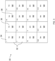
- Fig. 3 shows a visualisation of a portion 30 of the terrain elevation map 4.
- the terrain elevation map 4 is not actually a visual map as shown in Figs. 3 to 5 , but in reality comprises a plurality of data entries (map posts), each corresponding to a particular area on the Earth's surface and each comprising an elevation of the terrain for that area.
- the portion 30 of the terrain map 4 shown in Figs. 3 to 5 is illustrative only, and provided in order to aid understanding of the operation of the land-water calculation unit 6.
- the portion 30 of the terrain map 4 comprises sixteen map posts 32 arranged in a square.
- Each map post 32 comprises an arbitrary label 34 in order to aid the forthcoming description, each label 34 comprising a roman numeral from I to XVI, an elevation value 36, in metres, and a land/water label 38, which may comprise a 'W' to indicate that the corresponding map post is labelled as water, or an 'L' to indicate that the corresponding map post is labelled as land.
- the portion 30 comprises an arbitrary portion of the terrain map 4, however in normal operation of the navigation system 1, the portion of the terrain map 4 on which the following operation is carried out comprises a cache of the local terrain elevation data 14 surrounding the current estimated position 22 of the vehicle.
- the cache of the local terrain elevation data 14 is updated continually to follow the estimated position of the vehicle as it changes over time, and to allow the land-water calculation unit 6 and IAU 2 to have quick and efficient access to the local terrain elevation data 14.
- Fig. 3 illustrates the first stage in the process by which the land-water calculation unit 6 classifies the map posts 32 within the portion 30 of the terrain map 4 as being probably land, or probably water.
- This process operates on the principle that terrain elevation data for a body of water is typically the local minimum of terrain elevation data within a given portion of a terrain map 4, and that areas of land that are adjacent to the body of water are thereby at a higher elevation.
- the land-water calculation unit 6 classifies all map posts 32 of the portion 30 as water, as indicated by the labels 38 of Fig. 3 (each of which are labelled 'W').
- the IAU 2 is arranged to apply a Q-boost to the height bias state when the proportion 16 of map posts 32 that are labelled as land, as output by the land-water calculation unit 6, is between 5% and 95% for the subset of the cached portion of the terrain map 4. If the proportion 16 of map posts 32 that are labelled as land for the local portion (i.e. subset) of the terrain map 4 is between 5% and 95%, this indicates that the vehicle is over a transition between land and water, and therefore that the IAU 2 should take this into account when updating the system error state and the position estimate.
Landscapes
- Engineering & Computer Science (AREA)
- Remote Sensing (AREA)
- Radar, Positioning & Navigation (AREA)
- Physics & Mathematics (AREA)
- General Physics & Mathematics (AREA)
- Automation & Control Theory (AREA)
- Computer Networks & Wireless Communication (AREA)
- Electromagnetism (AREA)
- Navigation (AREA)
Description
- The present disclosure relates to the field of terrain referenced navigation systems. More particularly, this disclosure relates to the detection of land/water transitions in terrain referenced navigation systems.
- Terrain Referenced Navigation (TRN) systems are in service on a number of airborne platforms and integrate aircraft navigation data, radar altimeter data and stored terrain elevation data in order to generate a navigation solution. TRN systems are often used in conjunction with Inertial Navigation Systems (INS), which use inertial measurement sensors (e.g. gyroscopes, accelerometers, etc.) to provide a navigation solution. Such systems are sometimes referred to as Inertial Reference Units (IRUs). The navigation solutions often use INS error calibrating Kalman Filters as a means of integrating the navigation solutions provided by the TRN and the INS.
- Position estimates obtained from Inertial Navigation Systems typically drift at a rate of around 2 nautical miles per hour due to the accumulation of errors caused by accelerometers and gyroscopes over time. Navigation systems are able to correct for these errors, to an extent, by using further sources of position estimates, including satellite-based navigation solutions such as GPS, GNSS, etc. However, satellite-based navigation solutions are not reliable: signals can be jammed, spoofed, blocked, etc. which can lead to problems with navigation systems that rely too heavily on these satellite-based navigation solutions. TRN systems offer a further navigation solution that can allow navigation systems to correct for INS errors over time.
- Conventional TRN systems utilise Barometric-Inertial mixed altitude and radar altimeters in order to estimate terrain elevation beneath an aircraft. Measured terrain elevation estimates are then correlated with terrain elevation data, stored in a terrain elevation map, along the aircraft's travel path in order to produce a navigation solution - i.e. estimate the position of the aircraft.
-
US 5331562 A1 discloses a terrain referenced navigation system utilizing a five-state Kalman filter and a database that utilizes a state variable indicating whether the aircraft is headed over water or land. The accuracy of the filter is improved by ignoring filter coefficients over water. - When viewed from a first aspect this disclosure provides a terrain referenced navigation system comprising: at least one sensor arranged to measure the elevation of terrain below a current position of the navigation system; a terrain elevation map comprising a plurality of map posts that each comprise terrain elevation data; and a land-water detection unit arranged to calculate a proportion of land and/or water of at least a portion of the terrain elevation map based on the terrain elevation data of said portion of said terrain elevation map.
- Terrain maps typically store a fixed elevation for each entry, including entries that correspond to both areas of land and areas of water on the surface of the Earth. The elevation of bodies of water, however, rises and falls over time (e.g. as a result of tides, seasonal filling and evaporation of lakes, etc.). This can cause the actual elevation of water to differ from stored elevation values in the terrain map, which can cause errors in position estimates obtained from terrain-referenced navigation systems when such systems try to correlate the measurements of actual height with the stored map heights.
- The effect of inaccurate terrain elevation data over areas of water is particularly problematic over areas of transitions between land and water. When an aircraft equipped with a terrain referenced navigation system passes from land to water (or vice versa), the measured difference in elevation across the transition can differ from the expected difference in elevation based on the stored elevation values in the terrain elevation map. The discrepancy between the actual and expected values may be a number of meters. In practice, this can lead to the TRN outputting inaccurate position estimates and/or state error estimates (e.g. of position, velocity, attitude, etc.), as it may assume that the measured data is correct and therefore fail to correlate the aircraft's position with the correct position on the map (either matching to an incorrect position or making no match at all). This can lead to sharp spikes in navigation error over transitions between land and water. The TRN system disclosed herein comprises a land-water detection unit, which provides the ability for the navigation system to estimate a proportion of land and/or water of a portion of the terrain elevation map, using the terrain elevation data stored therein. The land-water detection unit allows the navigation system to detect areas of the terrain map that contain transitions between land and water, and allows the TRN system to compensate accordingly when passing over these areas, thereby reducing the effect of these transitions on navigational error.
- In a set of examples, the navigation system further comprises: an iterative algorithm unit arranged to determine a position estimate of the navigation system, wherein in each iteration the iterative algorithm unit is arranged to: receive the measured terrain elevation data; receive the proportion of land and/or water of at least a portion of the terrain elevation map from the land-water detection unit; determine whether the current position estimate of the navigation system is over a land-water transition based on the proportion of land and/or water received from the land-water detection unit; and update the position estimate for the next iteration based on the current position estimate, the measured terrain elevation data, the stored terrain elevation data and whether the current position estimate of the navigation system is over a land-water transition. Iterative algorithms are often used in navigation systems to take various observations and/or estimates and combine them into an optimal solution. Examples of such iterative algorithms include least squares estimators such as Kalman filters. By taking into account the extra information on the presence of a land-water transition, the iterative algorithm unit can provide an improved estimate of position. In particular, the presence or absence of a land-water transition may be used to change the way in which the other information is combined or processed to form the optimal solution.
- The iterative algorithm unit may be arranged to update the position estimate for the next iteration based on a correlation between measured terrain elevation data and stored terrain elevation data in the terrain elevation map. In a set of examples, the terrain referenced navigation system (TRN) further comprises an inertial navigation system (INS), and the iterative algorithm unit is arranged to update the position estimate for the next iteration based further on the signal(s) output by the INS. This provides additional input that the iterative algorithm unit can take into account when updating the position estimate for the next iteration, allowing the terrain referenced navigation system to produce a more accurate navigation solution. In some examples, the INS can produce a position estimate that is independent of a purely terrain based position estimate. In such examples the INS produces its position estimate based on integrating the outputs of the IMU (accelerometers and gyros) over time while the purely terrain based position estimate is produced by correlating measurements of the terrain elevation with the stored map of terrain elevation to give a best estimate of current position. In practice, both of these position estimates may be calculated and combined by the IAU based on inputs from the INS, the stored map of terrain elevation and the terrain elevation sensors. The way in which these two estimates are combined is determined by the iterative algorithm unit which may adjust its optimal solution based on the changes and the reliability of each estimate. Where a land-water transition is detected, the iterative algorithm unit may place less reliance on current measurements as the TRN estimate could be thrown off by an unexpected water level in such areas. Accordingly, the IAU effectively treats the unexpected water level as being of lower significance and does not adjust its optimal position solution so much in response to that unexpected water level.
- In a set of examples, the iterative algorithm unit is arranged to update the position estimate for the next iteration based on whether the current position estimate (i.e. the estimate of the previous iteration) is located above a land-water transition by increasing the uncertainty associated with the measured terrain elevation data. In doing so, the iterative algorithm unit effectively assumes that the measured terrain elevation data has a larger error than has been calculated by the normal mechanisms when it is over areas of transition between land and water. This forces the iterative algorithm unit to update the position estimate for the next iteration based more heavily on other sources of navigation (e.g. an INS) when passing over land-water transitions, and thus helps prevent navigation errors caused by discrepancies between measured elevation data and stored elevation data of areas of water. By increasing the uncertainty associated with the measured terrain elevation data, any discrepancy between the measured data and the stored map data is more likely to be within the expected uncertainty and is therefore less likely to cause errors within the iterative algorithm unit. The iterative algorithm is more likely to remain convergent in such circumstances.
- In a set of examples, the iterative algorithm unit comprises a Kalman filter. The iterative algorithm unit may be arranged to de-weight the measured terrain elevation data by increasing the modelled uncertainty of its knowledge of a height state (also known to those skilled in the art as a "Q"-boost) of the iterative algorithm unit when the iterative algorithm unit determines that the navigation system is located above a land-water transition. Iterative algorithm units, such as Kalman filters, typically utilise a "P"-matrix which holds the covariances of the error estimates of each available system state variable. Iterative algorithm units also typically utilise a "Q"-matrix which holds levels of uncertainty that are added to the P-matrix on each propagation cycle in order to model system noise and other effects, The state vector may include one or more height error states, with their associated entries in the P and Q matrices. The height states are therefore associated with the measured terrain elevation data as this is calculated based on height measurements taken by at least one sensor of the navigation system. By adding this theoretical noise to a state, the iterative algorithm unit assumes that said state has a larger error than it would without applying the Q-boost, and therefore does not take measurements associated with the state into account as strongly as other measurements when updating the position estimate for the next iteration. In other words, the iterative algorithm unit increases the uncertainty associated with (or reduces the weight of) the measurements associated with the height state (i.e. the measured terrain elevation data) when updating the position estimate for the next iteration. When referring to weights (or de-weighting), it will be appreciated that the various pieces of information may be combined together with weighting coefficients that indicate their respective importance or accuracy. One way to do this is to weight the measurements according to their estimated uncertainties, with more uncertain measurements given less weight than those with lower uncertainties.
- In a set of examples, the iterative algorithm unit is arranged to apply a Q-boost equal to a predetermined amount to the height state of the iterative algorithm unit when it determines that the navigation system is located above a land-water transition. In some examples the predetermined value may be greater than (0.5 m)2, preferably greater than (1 m)2, more preferably greater than (2 m)2, yet more preferably greater than (3 m)2.
- In a set of examples, the iterative algorithm unit is arranged to apply a Q-boost equal to an amount dynamically determined by the iterative algorithm based on other variables. Such variables may include local gradients, tide times, flight phase, etc.
- In a set of examples, the portion of the terrain elevation map for which the land-water detection unit calculates a proportion of land or water comprises a number of map posts (i.e. individual location data points) corresponding to an area surrounding (and optionally centred on) the current estimated position of the navigation system. The size and shape of the area for which the land-water detection unit calculates a proportion of land or water, and therefore the corresponding number of map posts, may depend upon the uncertainty in the current position estimate. The portion of the terrain elevation map for which the land-water detection unit calculates a proportion of land or water may comprise a subset of a larger cache comprising a predetermined number of map posts corresponding to an area surrounding the current position estimate.
- Many different algorithms could be used to determine from the terrain elevation map which map posts are likely to be land and which are likely to be water. However, in a set of examples, the land-water detection unit is arranged to classify a map post as probably land or probably water of at least a portion of the terrain elevation map that may comprise an area of less than 40000 (e.g. 200 by 200) map posts, preferably an area of less than 10000 (e.g. 100 by 100) map posts, more preferably an area of less than 2500 (e.g. 50 by 50) map posts, yet more preferably an area of less than or equal to 1000 (e.g. 30 by 30) map posts. In some embodiments, each map post comprises terrain elevation data for an area of less than 40000 m2 (e.g. 200 m by 200 m) on the Earth's surface, preferably an area of less than 10000 m2 (e.g. 100 m by 100 m), more preferably an area of less than 2500 m2 (e.g. 50 m by 50 m), yet more preferably an area of less than or equal to 1000 m2 (e.g. 30 m by 30 m). It will be appreciated that there is a trade-off between the resolution of the data points, the number of data points, the accuracy of the classification process and the processing power required to perform the correlation process.
- In a set of examples, the land-water detection unit is arranged to classify each map post as land or water for a portion of the terrain elevation map, the process of classifying each map post as land or water comprising: initially labelling as water all map posts within the portion of the terrain elevation map; changing to land the labels of all map posts that have an adjacent map post at a lower elevation in a first pass of the map posts within the portion of the terrain elevation map; and in repeated passes, changing to land the labels of all map posts that have an adjacent map post at the same elevation that is labelled as land, ceasing at the end of the first pass that results in no labels being changed. This algorithm allows the land-water detection unit to classify as land or water a portion of the terrain elevation map using only the terrain elevation data stored therein, enabling the land-water detection unit to be compatible with a variety of different existing terrain elevation maps, e.g. DTED (Digital Terrain Elevation Data), DTED2, etc., as the unit simply requires terrain elevation data to function. This algorithm operates on the principle that water generally flows down slopes to the lowest possible position. Therefore a local minimum in the terrain may be considered to be water. Any map post that has an adjacent map post that is at a lower elevation can be safely assumed to be land as it is at an upper region of a slope such that water would flow down it. Once all the sloping land has been categorized this way, any terrain that is at the same height as adjacent land can also be assumed to be land as the local water level has been established as being lower. Whatever remains is then assumed to be water. This approach may detect some small flat areas of land (e.g. a flat valley floor) as water, but it will reliably detect genuine areas of water. Being able to detect and compensate for the actual land-water transitions is of great benefit while the occasional increased error that may be associated with small flat areas of land (because they are incorrectly identified as water) has been found to have little detrimental effect on the accuracy of the system.
- It may be noted that the theory of identifying a map post as land when there is a lower adjacent post may fall down for large flowing rivers and waterfalls. However, in practice this is not a problem. The disclosure is mainly concerned with identification of boundaries at larger relatively static bodies of water such as lakes, seas, reservoirs, etc. Also, the database creators typically put an artificial lip of
height 1 metre around bodies of water where there is no higher terrain (e.g. at the top of a waterfall) such that the algorithm would still function correctly. - In a set of examples, the land-water detection unit is arranged to: classify each map post as land or water for a first portion of the terrain elevation map corresponding to a predetermined area surrounding the current position estimate; and calculate a proportion of land and/or water of a second portion of the terrain elevation map corresponding to a second area surrounding the current position estimate, wherein the second portion of the terrain elevation map is a subset of the first portion. The first portion of the terrain elevation map over which the land/water classification is performed may be cached for ease of access.
- In a set of examples the iterative algorithm unit is arranged to determine that the navigation system is located above a transition between land and water when the proportion of map posts within the second portion of the terrain elevation map that are labelled as land lies above a first predetermined threshold and below a second predetermined threshold, and to determine that the navigation system is not located above a land-water transition when the proportion of said map posts that are labelled as land does not lie above said first predetermined threshold and below said second predetermined threshold. It will be appreciated that the same process may be used with the proportion of water instead of the proportion of land. In some examples the first predetermined threshold is less than or equal to 20%, preferably less than or equal to 15%, more preferably less than or equal to 10%, yet more preferably less than or equal to 5%. In some examples the second predetermined threshold is greater than or equal to 80%, preferably greater than or equal to 85%, more preferably greater than or equal to 90%, more preferably greater than or equal to 95%. Such values for the first predetermined threshold and the second predetermined threshold allow transitions between land and water to be easily detected whilst reducing the occurrence of false detections of land-water transitions.
- It will be appreciated that the determination of a map post as land or water could be calculated in advance for the whole of, or a large portion of the terrain map, with the labels being stored alongside the elevation data for swift reference. However, modifying the map data may complicate matters from a software and regulatory perspective and therefore it is advantageous in certain examples to keep the standard terrain map unchanged and to calculate the land and water labels (and thus the land-water transitions) in real time on the cached portion of the terrain map that is currently in use for terrain based navigation (i.e. for position estimation). This cached portion is updated in a rolling manner as the position changes with new map points being loaded into the cache from the terrain map as the vehicle moves over new (uncached) terrain, while older map points are discarded when no longer needed (when the vehicle moves sufficiently far from those map points).
- When viewed from a second aspect the present disclosure provides a method of calculating a proportion of land and/or water of at least a portion of a terrain elevation map comprising a plurality of map posts that each comprise terrain elevation data, the method comprising: initially labelling as water all map posts within the portion of the terrain elevation map; changing to land the labels of all map posts that have an adjacent map post at a lower elevation; changing to land the labels of all map posts that have an adjacent map post at the same elevation that is labelled as land; and calculating the proportion of map posts that are labelled as land and/or water within the portion of the terrain elevation map.
- When viewed from a third aspect the present disclosure provides a method of classifying each map post as land or water of a portion of a terrain elevation map, the terrain elevation map comprising a plurality of map posts that each comprise terrain elevation data, the method comprising: initially labelling as water all map posts within the portion of the terrain elevation map; changing to land the labels of all map posts that have an adjacent map post at a lower elevation in a first pass of the map posts within the portion of the terrain elevation map; and in repeated passes, changing to land the labels of all map posts that have an adjacent map post at the same elevation that is labelled as land, ceasing at the end of the first pass that results in no labels being changed.
- It will be appreciated that all of the optional features described above in relation to the first aspect of the disclosure may also apply equally to the second aspect.
- One or more non-limiting examples will now be described, with reference to the accompanying drawings in which:
-
Fig. 1 shows a schematic block diagram of a navigation system in accordance with the present disclosure; -
Fig. 2 shows a schematic block diagram illustrating the hardware components of a navigation system in accordance with the present disclosure; -
Fig. 3 shows a visualisation of a portion of a terrain elevation map after a first stage of a land/water classification process in accordance with the present disclosure; -
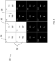
Fig. 4 shows a visualisation of a portion of a terrain elevation map after a second stage of a land/water classification process in accordance with the present disclosure; and -
Fig. 5 shows a visualisation of a portion of a terrain elevation map after a second stage of a land/water classification process in accordance with the present disclosure; -
Figure 1 schematically shows anavigation system 1. Thenavigation system 1 is suitable for a vehicle such as an aeroplane, a helicopter, etc. Thenavigation system 1 shown inFig. 1 comprises an iterative algorithm unit (IAU) 2, a terrain elevation map 4, a land-water calculation unit 6, an inertial navigation system (INS) 7, a radar altimeter (RADALT) 8 and abarometric altimeter 10. TheIAU 2 uses inputs from the terrain elevation map 4, the land-water calculation unit 6, theINS 7, theRADALT 8 and thebarometric altimeter 10 to derive an estimate of the vehicle'scurrent position 22, which it then outputs as theposition output 12. Theposition output 12 may comprise a further system of a vehicle to which thenavigation system 1 is attached, e.g. a navigation display, an autopilot system, a flight recording system, etc. - The terrain elevation map 4 comprises a plurality of map posts, each map post comprising terrain elevation data (i.e. a height above sea level) for an area on the Earth's surface. In this example, each map post comprises terrain elevation data for an area of 30m by 30m on the Earth's surface, The terrain elevation map 4 may be stored using any appropriate non-volatile storage means, including but not limited to hard-disk drives (HDD), solid state drives (SSD), etc. The terrain elevation map 4 is arranged to output
terrain elevation data 14 to both theIAU 2 and the land-water calculation unit 6. The terrain elevation map 4 may be arranged to output localterrain elevation data 14 to theIAU 2 and the land-water calculation unit 6 according to the current estimated position of thevehicle 22. - The
INS 7 comprises one or more inertial measurement units, for example accelerometers and gyroscopes, which measure the motion of the vehicle to which thenavigation system 1 is attached in order to allow a position estimate to be calculated. In this example, theINS 7 comprises three orthogonal accelerometers and three orthogonal gyroscopes. TheINS 7 outputs the measurements obtained using these accelerometers and gyroscopes to theIAU 2, in the form ofINS measurements 17. TheINS measurements 17 may comprise the signals as output by the accelerometers and gyroscopes, or a sequence of digital samples of the outputs of each of the accelerometers and gyroscopes. - The
radar altimeter 8 comprises a radar system arranged to measure the distance between the vehicle and the ground beneath it at any one time. In this example, theradar altimeter 8 uses time of flight measurements of radio waves emitted from antennas aboard the vehicle and detected at the vehicle after reflection off of the ground's surface. Theradar altimeter 8outputs measurements 18 of the vehicle's height above the ground to theIAU 2. - The
barometric altimeter 10 comprises an air pressure sensor (barometer) arranged to measure the air pressure over time. While the barometric altimeter may output these measurements directly to theIAU 2, in this example it is arranged to output an estimate of the vehicle's altitude 20 (i.e. height above sea level) to the IAU, calculated using the air pressure measurements. - The land-water calculation unit 6 is arranged to classify map posts for a region of the terrain elevation map 4 as land or water, and to calculate a proportion of land and/or water from the classifications of map posts for a region surrounding the current estimated position of the
vehicle 22. The land-water calculation unit 6 is arranged to output at 16 a proportion of map posts that are labelled as land for a region surrounding the current estimated position of thevehicle 22 to theIAU 2. The land-water calculation unit 6 receives the current estimatedposition 22 from theIAU 2, which it uses to calculate which map posts of the terrain map 4 correspond to the region surrounding the current estimatedposition 22. The operation of the land-water calculation unit 6 will be described in further detail with reference toFigs. 3 to 5 . - In this example, the
IAU 2 comprises a Kalman filter, arranged to iteratively update a system error state which comprises estimates of errors for a plurality of system variables, including, for example, a height state, a pitch state, a yaw state, a roll state, etc. TheIAU 2 is arranged to iteratively update the system error state according to inputs from the terrain elevation map 4, the land-water calculation unit 6, theINS 7, theradar altimeter 8 and thebarometric altimeter 10, and output acurrent position estimate 22 based on the current system state and the position estimate of the previous iteration, using variations on standard Kalman filter algorithms which are well known in the art. In this example, theIAU 2 holds a "P"-matrix which holds the covariances of the error estimates of each available system state variable, as well as a "Q"-matrix which holds levels of uncertainty that are added to the P-matrix on each iteration in order to model system noise and other effects. When theIAU 2 increases a value within the Q-matrix corresponding to a system state variable, the corresponding error within the P-matrix increases accordingly to take this into account. In other words, theIAU 2 is able to apply a "Q-boost" to the estimated error of a particular state variable stored within the P-matrix in order to cause theIAU 2 to apply less weight to measurements corresponding to that state variable when updating the system error state and position estimate, - In this example, the
IAU 2 is arranged to calculate a terrain-based position estimate which it uses to update the system error state and theposition estimate 22 for the next iteration. TheIAU 2 calculates the terrain-based position estimate by correlating estimates of terrain elevation obtained using measurements from theradar altimeter 8,barometric altimeter 10 andINS 7. More specifically, theIAU 2 calculates a barometric-inertial mixed altitude by combining measurements from theINS 7 and from thebarometric altimeter 10, the barometric-inertial mixed altitude comprising an estimate of the vehicles altitude (i.e height above sea level) at any given time. TheIAU 2 then subtracts measurements of the vehicle's height above the ground beneath it obtained from theradar altimeter 8 from the barometric-inertial mixed altitude in order to obtain an estimate of the terrain height beneath the vehicle. By doing this over a period of time, theIAU 2 is able to calculate a track of terrain height measurements. TheIAU 2 is arranged to correlate the track of terrain height measurements with the localterrain elevation data 14, obtained from the terrain elevation map 4, and use said correlation in order to provide a moreaccurate position estimate 22 in each iteration. In particular, by performing this correlation between measurements of terrain height and stored terrain elevation data, the position estimate of the vehicle output by theIAU 2 is subjected to a lower level of drift over time. -
Fig. 2 is a schematic block diagram illustrating the hardware components of thenavigation system 1. Shown are aprocessor 24, coupled to a memory 26 (e.g. by a memory bus), which make up the hardware components of theIAU 2. Theprocessor 24 may comprise any suitable processing hardware, for example a central processing unit (CPU), a field-programmable gate array (FPGA), etc. Thememory 26 may comprise any suitable computer-readable memory, for example random access memory (RAM) Flash memory, etc. In this example, theprocessor 24 andmemory 26, as well as performing the functions of theIAU 2, also perform the functions of the land-water calculation unit 6 shown inFig. 1 . Theprocessor 24 is arranged to update the system error state and position estimate, as described previously with reference to theIAU 2 andFig. 1 , and output the current position estimate to theposition output 12, which may communicated to a further system of the vehicle to which thenavigation system 1 is attached (e.g. a navigation display). - Also coupled to the
processor 24 is the storage 28 (e.g. by a memory bus). Stored within thestorage 28 is the terrain elevation map 4. Thestorage 28 may comprise any suitable non-volatile computer memory, including but not limited to a hard-disk drive (HDD), solid state drive (SSD), etc. Thestorage 28 outputs terrain elevation data to theprocessor 24, allowing theprocessor 24 to perform its functions both as theIAU 2 and the land-water calculation unit 6. - Also coupled to the
processor 24 are theINS 7, which in this example comprises threeorthogonal accelerometers 21 and threeorthogonal gyroscopes 23, theradar altimeter 8, and thebarometric altimeter 10. The operation of theradar altimeter 8, barometric altimeter andINS 7 are described above in further detail with reference toFig. 1 . - The operation of the land-water calculation unit 6 will now be described in detail with reference to
Figs. 3 to 5 , which illustrate the three main stages by which the land-water calculation unit 6 is arranged to classify map posts within a portion of the terrain map 4 as being probably land, or probably water.Fig. 3 shows a visualisation of aportion 30 of the terrain elevation map 4. It will be appreciated that the terrain elevation map 4 is not actually a visual map as shown inFigs. 3 to 5 , but in reality comprises a plurality of data entries (map posts), each corresponding to a particular area on the Earth's surface and each comprising an elevation of the terrain for that area. Theportion 30 of the terrain map 4 shown inFigs. 3 to 5 is illustrative only, and provided in order to aid understanding of the operation of the land-water calculation unit 6. - The
portion 30 of the terrain map 4 comprises sixteenmap posts 32 arranged in a square. Each map post 32 comprises anarbitrary label 34 in order to aid the forthcoming description, eachlabel 34 comprising a roman numeral from I to XVI, anelevation value 36, in metres, and a land/water label 38, which may comprise a 'W' to indicate that the corresponding map post is labelled as water, or an 'L' to indicate that the corresponding map post is labelled as land. In this example, theportion 30 comprises an arbitrary portion of the terrain map 4, however in normal operation of thenavigation system 1, the portion of the terrain map 4 on which the following operation is carried out comprises a cache of the localterrain elevation data 14 surrounding the current estimatedposition 22 of the vehicle. The cache of the localterrain elevation data 14 is updated continually to follow the estimated position of the vehicle as it changes over time, and to allow the land-water calculation unit 6 andIAU 2 to have quick and efficient access to the localterrain elevation data 14. -
Fig. 3 illustrates the first stage in the process by which the land-water calculation unit 6 classifies the map posts 32 within theportion 30 of the terrain map 4 as being probably land, or probably water. This process operates on the principle that terrain elevation data for a body of water is typically the local minimum of terrain elevation data within a given portion of a terrain map 4, and that areas of land that are adjacent to the body of water are thereby at a higher elevation. Initially, the land-water calculation unit 6 classifies all map posts 32 of theportion 30 as water, as indicated by thelabels 38 ofFig. 3 (each of which are labelled 'W'). -
Fig. 4 illustrates the second stage in the land/water classification process. During this stage, the land-water calculation unit 6 changes the classification from water to land of all mapposts 32 within theportion 30 which have an adjacent map post at a lower elevation. In this example, the land-water calculation unit 6 classifies map posts VII, VIII, IX, X, XI, XII, XIV and XV as land (indicated by the black colour, and the label 'L'), as each of these has an adjacent map post at a lower elevation. For example, map post VII (which has an elevation of 2m) is adjacent to map posts III and VI (both of which have an elevation of 1m). The elevation of map posts III and VI is therefore less than that of map post VII, and therefore the land-water calculation unit 6 changes the label of map post VII to land. -
Fig. 5 illustrates the third stage in the land/water classification process. During this stage, the land-water calculation unit 6 classifies all map posts 32 within theportion 30 as land which have anadjacent map post 32 at the same elevation which is already labelled as land. In this example, the land-water calculation unit 6 does this repeatedly - that is over a series of repeated passes until a pass is completed in which the labels of no map posts 32 are changed, at which point the land-water calculation unit 6 ceases the land/water classification process. This operation is performed repeatedly as each pass in which a label of amap post 32 is changed from water to land requires a further pass to be completed in order to make sure that the change has not enabled further map posts 32 to have their labels changed from water to land. - In the example shown in
Fig. 5 , two passes are completed. In the first pass, the land-water calculation unit 6 changes the label of map posts XIII and XVI to land, as both of these map posts are adjacent to at least one map post at the same elevation that has already been labelled as land. For example, map post XIII is adjacent to map posts IX and XIV, both of which were labelled as land during the second stage of the land/water classification process (shown inFig. 2 ) and both of which have the same elevation (3m) as map post XIII. Similarly, map post XVI is adjacent to map posts XII and XV at the same height of 4m. In the second pass, the land-water calculation unit does not change the labels of any of the map posts 32 within theportion 30, as there are no remaining map posts that are not already labelled as land that have an adjacent map post at the same elevation which is already labelled as land. Therefore, after the second pass, the land-water calculation unit 6 determines that the land/water classification process for thisportion 30 of the terrain map 4 is completed. - The land-water calculation unit 6 is then arranged to calculate and output a
proportion 16 of map posts 32 that are labelled as land for a subset of the portion of map posts 32 for which the land/water classification process has been performed (which in this example comprises the cached portion of the terrain elevation map 4). During normal operation of thenavigation system 1, the land-water calculation unit 6 calculates theproportion 16 of map posts 32 that are labelled as land of a subset of the cached portion of the terrain elevation map 4, the subset corresponding to an area surrounding thecurrent position estimate 22. The subset may be a predetermined number of map posts 32 corresponding to an area centred on thecurrent position estimate 22, or it may be a dynamic number of map posts 32 corresponding to an area centred on thecurrent position estimate 22, the number of map posts 32 (and therefore the size of the corresponding area) being dependant on the current estimated uncertainty in thecurrent position estimate 22. For example, if the estimated uncertainty in thecurrent position estimate 22 is large, the subset of the cached portion which the land-water calculation unit 6 uses to calculate theproportion 16 may be increased in size accordingly. - In this example, the
IAU 2 is arranged to apply a Q-boost to the height bias state when theproportion 16 of map posts 32 that are labelled as land, as output by the land-water calculation unit 6, is between 5% and 95% for the subset of the cached portion of the terrain map 4. If theproportion 16 of map posts 32 that are labelled as land for the local portion (i.e. subset) of the terrain map 4 is between 5% and 95%, this indicates that the vehicle is over a transition between land and water, and therefore that theIAU 2 should take this into account when updating the system error state and the position estimate. - Applying a Q-boost to the height bias state in this way causes the
IAU 2 to increase the uncertainty associated with the height bias state. This causes theIAU 2 to reduce the weight applied to the height bias state when updating the system error state and theposition estimate 22, and thus helps reduce the effect of errors that result from passing over areas containing transitions from land to water (as explained previously). - Examples of this disclosure thus provide an improved terrain referenced navigation system by providing the ability to detect and account for transitions between land and water when a vehicle passes over these.
Claims (15)
- A terrain referenced navigation system (1) comprising:at least one sensor (8, 10) arranged to measure the elevation of terrain below a current position of the navigation system (1); anda terrain elevation map (4) comprising a plurality of map posts (32) that each comprise terrain elevation data (14);characterised in that the navigation system (1) comprises:
a land-water detection unit (6) arranged to calculate a proportion (16) of land and/or water of at least a portion (30) of the terrain elevation map (4) based on the terrain elevation data (14) of said portion (30) of the terrain elevation map (4). - The navigation system (1) of claim 1, further comprising:
an iterative algorithm unit (2) arranged to determine a position estimate (22) of the navigation system, wherein in each iteration the iterative algorithm unit (2) is arranged to:receive the measured terrain elevation data (18, 20);receive the proportion (16) of land and/or water of at least a portion (30) of the terrain elevation map (4) from the land-water detection unit (6);determine whether the current position estimate (22) of the navigation system (1) is over a land-water transition based on the proportion (16) of land and/or water received from the land-water detection unit (6); andupdate the position estimate for the next iteration based on the current position estimate (22), the measured terrain elevation data (18, 20), the stored terrain elevation data (14) and whether the current position estimate (22) of the navigation system (1) is over a land-water transition. - The navigation system (1) of claim 2, wherein the iterative algorithm unit (2) is arranged to update the position estimate for the next iteration based on a correlation between measured terrain elevation data (18, 20) and stored terrain elevation data (14) in the terrain elevation map (4).
- The navigation system (1) of claim 2 or 3, further comprising an inertial navigation system (7) and wherein the iterative algorithm unit (2) is arranged to update the position estimate for the next iteration further based on the signal(s) (17) output by the inertial navigation system (17).
- The navigation system (1) of any of claims 2 to 4, wherein the iterative algorithm unit (2) is arranged to increase an uncertainty associated with the measured terrain elevation data (18, 20) when the iterative algorithm unit (2) determines that the navigation system (1) is located above a land-water transition.
- The navigation system (1) of any of any of claims 2 to 5, wherein the iterative algorithm unit (2) is arranged to apply a Q-boost to a height state of the iterative algorithm unit (2) when the iterative algorithm unit (2) determines that the navigation system (1) is located above a land-water transition.
- The navigation system (1) of claim 6, wherein the Q-boost applied to the height state is equal to a predetermined amount.
- The navigation system (1) of claim 7, wherein the predetermined amount is greater than (0.5m)2, preferably wherein the predetermined amount is greater than (1m)2, more preferably wherein the predetermined amount is greater than (2m)2, more preferably wherein the predetermined amount is greater than or equal to (3m)2.
- The navigation system (1) of any preceding claim, wherein the land-water detection unit (6) is arranged to classify each map post (32) as land or water for a portion (30) of the terrain elevation map (4), the process of classifying each map post (32) as land or water comprising:initially labelling as water all map posts (32) within the portion (30) of the terrain elevation map (4);changing to land the labels (38) of all map posts (32) that have an adjacent map post (32) at a lower elevation (36) in a first pass of the map posts (32) within the portion (30) of the terrain elevation map (4); andin repeated passes changing to land the labels (38) of all map posts (32) that have an adjacent map post (32) at the same elevation (36) that is labelled as land, ceasing at the end of the first pass that results in no labels (38) being changed.
- The navigation system (1) of any preceding claim, wherein the land-water detection unit (6) is arranged to:classify each map post (32) as land or water for a first portion (30) of the terrain elevation map (4) corresponding to a predetermined area surrounding the current position estimate (22); andcalculate a proportion of land and/or water of a second portion of the terrain elevation map (4) corresponding to a second area surrounding the current position estimate (22), wherein the second portion of the terrain elevation map (4) is a subset of the first portion (30) of the terrain elevation map (4).
- The navigation system (1) of claim 10, wherein the first portion (30) of the terrain elevation map (4) comprises a cache of a predetermined number of map posts (32) surrounding the current position estimate (22), and the size of the second portion of the terrain elevation map (4) is dependent upon the uncertainty in the current position estimate (22).
- The navigation system (1) of claim 10 or 11, wherein the iterative algorithm unit (2) is arranged to determine that the navigation system (1) is located above a land-water transition when the proportion of map posts (32) within the second portion of the terrain elevation map (4) that are labelled as land lies above a first predetermined threshold and below a second predetermined threshold, and to determine that the navigation system (1) is not located above a land-water transition when the proportion of said map posts (32) that are labelled as land does not lie above said first predetermined threshold and below said second predetermined threshold.
- The navigation system (1) of claim 12, wherein the first predetermined threshold is less than or equal to 5%, and the second predetermined threshold is greater than or equal to 95%.
- The navigation system (1) of any preceding claim, wherein the iterative algorithm unit (2) is a Kalman filter.
- A method of calculating a proportion of land to water of at least portion (30) of a terrain elevation map (4) comprising a plurality of map posts (32) that each comprise terrain elevation data (14), the method comprising:initially labelling as water all map posts (32) within the portion (30) of the terrain elevation map (4);changing to land the labels (38) of all map posts (32) that have an adjacent map post (32) at a lower elevation (36);changing to land the labels (38) of all map posts (32) that have an adjacent map post (32) at the same elevation (36) that is labelled as land; andcalculating the proportion of map posts (32) that are labelled as land and/or water within the portion (30) of the terrain elevation map (4).
Priority Applications (4)
| Application Number | Priority Date | Filing Date | Title |
|---|---|---|---|
| EP20275164.0A EP3988900B1 (en) | 2020-10-23 | 2020-10-23 | Terrain referenced navigation system |
| KR1020210121436A KR20220054178A (en) | 2020-10-23 | 2021-09-13 | Terrain referenced navigation system |
| US17/506,903 US12259467B2 (en) | 2020-10-23 | 2021-10-21 | Terrain referenced navigation system |
| JP2021172773A JP2022069425A (en) | 2020-10-23 | 2021-10-22 | Terrain referenced navigation system |
Applications Claiming Priority (1)
| Application Number | Priority Date | Filing Date | Title |
|---|---|---|---|
| EP20275164.0A EP3988900B1 (en) | 2020-10-23 | 2020-10-23 | Terrain referenced navigation system |
Publications (2)
| Publication Number | Publication Date |
|---|---|
| EP3988900A1 EP3988900A1 (en) | 2022-04-27 |
| EP3988900B1 true EP3988900B1 (en) | 2024-07-10 |
Family
ID=73014448
Family Applications (1)
| Application Number | Title | Priority Date | Filing Date |
|---|---|---|---|
| EP20275164.0A Active EP3988900B1 (en) | 2020-10-23 | 2020-10-23 | Terrain referenced navigation system |
Country Status (4)
| Country | Link |
|---|---|
| US (1) | US12259467B2 (en) |
| EP (1) | EP3988900B1 (en) |
| JP (1) | JP2022069425A (en) |
| KR (1) | KR20220054178A (en) |
Family Cites Families (8)
| Publication number | Priority date | Publication date | Assignee | Title |
|---|---|---|---|---|
| US3659085A (en) * | 1970-04-30 | 1972-04-25 | Sierra Research Corp | Computer determining the location of objects in a coordinate system |
| US5335181A (en) | 1992-01-15 | 1994-08-02 | Honeywell Inc. | Terrain referenced navigation--woods data base model |
| US5331562A (en) * | 1992-01-16 | 1994-07-19 | Honeywell Inc. | Terrain referenced navigation-adaptive filter distribution |
| US7822275B2 (en) * | 2007-06-04 | 2010-10-26 | Objectvideo, Inc. | Method for detecting water regions in video |
| US8788128B1 (en) * | 2008-08-01 | 2014-07-22 | Rockwell Collins, Inc. | Precision navigation for landing |
| CN106297416A (en) | 2016-08-27 | 2017-01-04 | 桂林信通科技有限公司 | A kind of aircraft coastal waters alarm method and system |
| US20180130193A1 (en) * | 2016-11-09 | 2018-05-10 | Regents Of The University Of Minnesota | Simultaneous estimation of location elevations and water levels |
| US11940277B2 (en) * | 2018-05-29 | 2024-03-26 | Regents Of The University Of Minnesota | Vision-aided inertial navigation system for ground vehicle localization |
-
2020
- 2020-10-23 EP EP20275164.0A patent/EP3988900B1/en active Active
-
2021
- 2021-09-13 KR KR1020210121436A patent/KR20220054178A/en active Pending
- 2021-10-21 US US17/506,903 patent/US12259467B2/en active Active
- 2021-10-22 JP JP2021172773A patent/JP2022069425A/en active Pending
Also Published As
| Publication number | Publication date |
|---|---|
| JP2022069425A (en) | 2022-05-11 |
| US12259467B2 (en) | 2025-03-25 |
| EP3988900A1 (en) | 2022-04-27 |
| KR20220054178A (en) | 2022-05-02 |
| US20220128686A1 (en) | 2022-04-28 |
Similar Documents
| Publication | Publication Date | Title |
|---|---|---|
| EP3260877B1 (en) | Integrity monitoring of radar altimeters | |
| EP2784445B1 (en) | Selected aspects of advanced receiver autonomous integrity monitoring application to kalman filter based navigation filter | |
| US8788128B1 (en) | Precision navigation for landing | |
| EP3084350B1 (en) | Method and system for generating a geoid via three computation spaces and airborne-acquired gravity data | |
| US5331562A (en) | Terrain referenced navigation-adaptive filter distribution | |
| US9663200B2 (en) | System and method for the navigation of a movable vehicle, suitable for determining and displaying a safe navigation zone | |
| US7486227B2 (en) | System and method for removal of sea-state bias in satellite altimetry data | |
| US20120203519A1 (en) | Method for calculating a navigation phase in a navigation system involving terrain correlation | |
| US11029159B2 (en) | Navigation system | |
| US11321563B2 (en) | Handling of ARAIM terrain database induced errors | |
| US20240175984A1 (en) | Information processing device, control method, program, and storage medium | |
| EP3722834B1 (en) | Integrity monitoring of primary and derived parameters | |
| US11428802B2 (en) | Localization using particle filtering and image registration of radar against elevation datasets | |
| US6256264B1 (en) | Localization of a submerged tow vehicle (lost) | |
| US10048370B2 (en) | Estimating weather and ground reflectivity with doppler spectral information | |
| EP3988900B1 (en) | Terrain referenced navigation system | |
| Quist | UAV navigation and radar odometry | |
| JP3962403B2 (en) | Advanced computing device and method | |
| US6725153B2 (en) | System and a method for navigating a vehicle | |
| CN116710909B (en) | Electronic device for storing a topographic database, method for generating such a database, avionics system, monitoring method and related computer program | |
| EP4724773A1 (en) | System for gravity map aided navigation | |
| Haydon et al. | Trusted inertial terrain-aided navigation (TITAN) | |
| EP3929627B1 (en) | Split vertical advanced receiver autonomous integrity monitoring | |
| RU2389042C2 (en) | Method of determining protective limit around position of moving body calculated from satellite signals | |
| Turan et al. | Flight test results of terrain referenced aircraft navigation with laser altimeter |
Legal Events
| Date | Code | Title | Description |
|---|---|---|---|
| PUAI | Public reference made under article 153(3) epc to a published international application that has entered the european phase |
Free format text: ORIGINAL CODE: 0009012 |
|
| STAA | Information on the status of an ep patent application or granted ep patent |
Free format text: STATUS: THE APPLICATION HAS BEEN PUBLISHED |
|
| AK | Designated contracting states |
Kind code of ref document: A1 Designated state(s): AL AT BE BG CH CY CZ DE DK EE ES FI FR GB GR HR HU IE IS IT LI LT LU LV MC MK MT NL NO PL PT RO RS SE SI SK SM TR |
|
| STAA | Information on the status of an ep patent application or granted ep patent |
Free format text: STATUS: REQUEST FOR EXAMINATION WAS MADE |
|
| 17P | Request for examination filed |
Effective date: 20221011 |
|
| RBV | Designated contracting states (corrected) |
Designated state(s): AL AT BE BG CH CY CZ DE DK EE ES FI FR GB GR HR HU IE IS IT LI LT LU LV MC MK MT NL NO PL PT RO RS SE SI SK SM TR |
|
| RIC1 | Information provided on ipc code assigned before grant |
Ipc: G01C 21/20 20060101ALI20231109BHEP Ipc: G01C 21/00 20060101AFI20231109BHEP |
|
| GRAP | Despatch of communication of intention to grant a patent |
Free format text: ORIGINAL CODE: EPIDOSNIGR1 |
|
| STAA | Information on the status of an ep patent application or granted ep patent |
Free format text: STATUS: GRANT OF PATENT IS INTENDED |
|
| INTG | Intention to grant announced |
Effective date: 20240202 |
|
| GRAS | Grant fee paid |
Free format text: ORIGINAL CODE: EPIDOSNIGR3 |
|
| GRAA | (expected) grant |
Free format text: ORIGINAL CODE: 0009210 |
|
| STAA | Information on the status of an ep patent application or granted ep patent |
Free format text: STATUS: THE PATENT HAS BEEN GRANTED |
|
| AK | Designated contracting states |
Kind code of ref document: B1 Designated state(s): AL AT BE BG CH CY CZ DE DK EE ES FI FR GB GR HR HU IE IS IT LI LT LU LV MC MK MT NL NO PL PT RO RS SE SI SK SM TR |
|
| REG | Reference to a national code |
Ref country code: CH Ref legal event code: EP |
|
| REG | Reference to a national code |
Ref country code: DE Ref legal event code: R096 Ref document number: 602020033686 Country of ref document: DE |
|
| REG | Reference to a national code |
Ref country code: LT Ref legal event code: MG9D |
|
| REG | Reference to a national code |
Ref country code: NL Ref legal event code: MP Effective date: 20240710 |
|
| PG25 | Lapsed in a contracting state [announced via postgrant information from national office to epo] |
Ref country code: PT Free format text: LAPSE BECAUSE OF FAILURE TO SUBMIT A TRANSLATION OF THE DESCRIPTION OR TO PAY THE FEE WITHIN THE PRESCRIBED TIME-LIMIT Effective date: 20241111 |
|
| REG | Reference to a national code |
Ref country code: AT Ref legal event code: MK05 Ref document number: 1702387 Country of ref document: AT Kind code of ref document: T Effective date: 20240710 |
|
| PG25 | Lapsed in a contracting state [announced via postgrant information from national office to epo] |
Ref country code: NL Free format text: LAPSE BECAUSE OF FAILURE TO SUBMIT A TRANSLATION OF THE DESCRIPTION OR TO PAY THE FEE WITHIN THE PRESCRIBED TIME-LIMIT Effective date: 20240710 |
|
| PG25 | Lapsed in a contracting state [announced via postgrant information from national office to epo] |
Ref country code: PT Free format text: LAPSE BECAUSE OF FAILURE TO SUBMIT A TRANSLATION OF THE DESCRIPTION OR TO PAY THE FEE WITHIN THE PRESCRIBED TIME-LIMIT Effective date: 20241111 Ref country code: NL Free format text: LAPSE BECAUSE OF FAILURE TO SUBMIT A TRANSLATION OF THE DESCRIPTION OR TO PAY THE FEE WITHIN THE PRESCRIBED TIME-LIMIT Effective date: 20240710 |
|
| PG25 | Lapsed in a contracting state [announced via postgrant information from national office to epo] |
Ref country code: NO Free format text: LAPSE BECAUSE OF FAILURE TO SUBMIT A TRANSLATION OF THE DESCRIPTION OR TO PAY THE FEE WITHIN THE PRESCRIBED TIME-LIMIT Effective date: 20241010 |
|
| PG25 | Lapsed in a contracting state [announced via postgrant information from national office to epo] |
Ref country code: GR Free format text: LAPSE BECAUSE OF FAILURE TO SUBMIT A TRANSLATION OF THE DESCRIPTION OR TO PAY THE FEE WITHIN THE PRESCRIBED TIME-LIMIT Effective date: 20241011 Ref country code: PL Free format text: LAPSE BECAUSE OF FAILURE TO SUBMIT A TRANSLATION OF THE DESCRIPTION OR TO PAY THE FEE WITHIN THE PRESCRIBED TIME-LIMIT Effective date: 20240710 Ref country code: FI Free format text: LAPSE BECAUSE OF FAILURE TO SUBMIT A TRANSLATION OF THE DESCRIPTION OR TO PAY THE FEE WITHIN THE PRESCRIBED TIME-LIMIT Effective date: 20240710 |
|
| PG25 | Lapsed in a contracting state [announced via postgrant information from national office to epo] |
Ref country code: BG Free format text: LAPSE BECAUSE OF FAILURE TO SUBMIT A TRANSLATION OF THE DESCRIPTION OR TO PAY THE FEE WITHIN THE PRESCRIBED TIME-LIMIT Effective date: 20240710 |
|
| PG25 | Lapsed in a contracting state [announced via postgrant information from national office to epo] |
Ref country code: LV Free format text: LAPSE BECAUSE OF FAILURE TO SUBMIT A TRANSLATION OF THE DESCRIPTION OR TO PAY THE FEE WITHIN THE PRESCRIBED TIME-LIMIT Effective date: 20240710 |
|
| PG25 | Lapsed in a contracting state [announced via postgrant information from national office to epo] |
Ref country code: AT Free format text: LAPSE BECAUSE OF FAILURE TO SUBMIT A TRANSLATION OF THE DESCRIPTION OR TO PAY THE FEE WITHIN THE PRESCRIBED TIME-LIMIT Effective date: 20240710 Ref country code: IS Free format text: LAPSE BECAUSE OF FAILURE TO SUBMIT A TRANSLATION OF THE DESCRIPTION OR TO PAY THE FEE WITHIN THE PRESCRIBED TIME-LIMIT Effective date: 20241110 |
|
| PG25 | Lapsed in a contracting state [announced via postgrant information from national office to epo] |
Ref country code: HR Free format text: LAPSE BECAUSE OF FAILURE TO SUBMIT A TRANSLATION OF THE DESCRIPTION OR TO PAY THE FEE WITHIN THE PRESCRIBED TIME-LIMIT Effective date: 20240710 |
|
| PG25 | Lapsed in a contracting state [announced via postgrant information from national office to epo] |
Ref country code: ES Free format text: LAPSE BECAUSE OF FAILURE TO SUBMIT A TRANSLATION OF THE DESCRIPTION OR TO PAY THE FEE WITHIN THE PRESCRIBED TIME-LIMIT Effective date: 20240710 Ref country code: RS Free format text: LAPSE BECAUSE OF FAILURE TO SUBMIT A TRANSLATION OF THE DESCRIPTION OR TO PAY THE FEE WITHIN THE PRESCRIBED TIME-LIMIT Effective date: 20241010 |
|
| PG25 | Lapsed in a contracting state [announced via postgrant information from national office to epo] |
Ref country code: RS Free format text: LAPSE BECAUSE OF FAILURE TO SUBMIT A TRANSLATION OF THE DESCRIPTION OR TO PAY THE FEE WITHIN THE PRESCRIBED TIME-LIMIT Effective date: 20241010 Ref country code: PL Free format text: LAPSE BECAUSE OF FAILURE TO SUBMIT A TRANSLATION OF THE DESCRIPTION OR TO PAY THE FEE WITHIN THE PRESCRIBED TIME-LIMIT Effective date: 20240710 Ref country code: NO Free format text: LAPSE BECAUSE OF FAILURE TO SUBMIT A TRANSLATION OF THE DESCRIPTION OR TO PAY THE FEE WITHIN THE PRESCRIBED TIME-LIMIT Effective date: 20241010 Ref country code: LV Free format text: LAPSE BECAUSE OF FAILURE TO SUBMIT A TRANSLATION OF THE DESCRIPTION OR TO PAY THE FEE WITHIN THE PRESCRIBED TIME-LIMIT Effective date: 20240710 Ref country code: IS Free format text: LAPSE BECAUSE OF FAILURE TO SUBMIT A TRANSLATION OF THE DESCRIPTION OR TO PAY THE FEE WITHIN THE PRESCRIBED TIME-LIMIT Effective date: 20241110 Ref country code: HR Free format text: LAPSE BECAUSE OF FAILURE TO SUBMIT A TRANSLATION OF THE DESCRIPTION OR TO PAY THE FEE WITHIN THE PRESCRIBED TIME-LIMIT Effective date: 20240710 Ref country code: GR Free format text: LAPSE BECAUSE OF FAILURE TO SUBMIT A TRANSLATION OF THE DESCRIPTION OR TO PAY THE FEE WITHIN THE PRESCRIBED TIME-LIMIT Effective date: 20241011 Ref country code: FI Free format text: LAPSE BECAUSE OF FAILURE TO SUBMIT A TRANSLATION OF THE DESCRIPTION OR TO PAY THE FEE WITHIN THE PRESCRIBED TIME-LIMIT Effective date: 20240710 Ref country code: ES Free format text: LAPSE BECAUSE OF FAILURE TO SUBMIT A TRANSLATION OF THE DESCRIPTION OR TO PAY THE FEE WITHIN THE PRESCRIBED TIME-LIMIT Effective date: 20240710 Ref country code: BG Free format text: LAPSE BECAUSE OF FAILURE TO SUBMIT A TRANSLATION OF THE DESCRIPTION OR TO PAY THE FEE WITHIN THE PRESCRIBED TIME-LIMIT Effective date: 20240710 Ref country code: AT Free format text: LAPSE BECAUSE OF FAILURE TO SUBMIT A TRANSLATION OF THE DESCRIPTION OR TO PAY THE FEE WITHIN THE PRESCRIBED TIME-LIMIT Effective date: 20240710 |
|
| REG | Reference to a national code |
Ref country code: DE Ref legal event code: R097 Ref document number: 602020033686 Country of ref document: DE |
|
| PG25 | Lapsed in a contracting state [announced via postgrant information from national office to epo] |
Ref country code: DK Free format text: LAPSE BECAUSE OF FAILURE TO SUBMIT A TRANSLATION OF THE DESCRIPTION OR TO PAY THE FEE WITHIN THE PRESCRIBED TIME-LIMIT Effective date: 20240710 Ref country code: RO Free format text: LAPSE BECAUSE OF FAILURE TO SUBMIT A TRANSLATION OF THE DESCRIPTION OR TO PAY THE FEE WITHIN THE PRESCRIBED TIME-LIMIT Effective date: 20240710 Ref country code: SM Free format text: LAPSE BECAUSE OF FAILURE TO SUBMIT A TRANSLATION OF THE DESCRIPTION OR TO PAY THE FEE WITHIN THE PRESCRIBED TIME-LIMIT Effective date: 20240710 |
|
| PG25 | Lapsed in a contracting state [announced via postgrant information from national office to epo] |
Ref country code: EE Free format text: LAPSE BECAUSE OF FAILURE TO SUBMIT A TRANSLATION OF THE DESCRIPTION OR TO PAY THE FEE WITHIN THE PRESCRIBED TIME-LIMIT Effective date: 20240710 |
|
| PG25 | Lapsed in a contracting state [announced via postgrant information from national office to epo] |
Ref country code: CZ Free format text: LAPSE BECAUSE OF FAILURE TO SUBMIT A TRANSLATION OF THE DESCRIPTION OR TO PAY THE FEE WITHIN THE PRESCRIBED TIME-LIMIT Effective date: 20240710 |
|
| PG25 | Lapsed in a contracting state [announced via postgrant information from national office to epo] |
Ref country code: SK Free format text: LAPSE BECAUSE OF FAILURE TO SUBMIT A TRANSLATION OF THE DESCRIPTION OR TO PAY THE FEE WITHIN THE PRESCRIBED TIME-LIMIT Effective date: 20240710 Ref country code: IT Free format text: LAPSE BECAUSE OF FAILURE TO SUBMIT A TRANSLATION OF THE DESCRIPTION OR TO PAY THE FEE WITHIN THE PRESCRIBED TIME-LIMIT Effective date: 20240710 |
|
| PLBE | No opposition filed within time limit |
Free format text: ORIGINAL CODE: 0009261 |
|
| STAA | Information on the status of an ep patent application or granted ep patent |
Free format text: STATUS: NO OPPOSITION FILED WITHIN TIME LIMIT |
|
| REG | Reference to a national code |
Ref country code: CH Ref legal event code: PL |
|
| 26N | No opposition filed |
Effective date: 20250411 |
|
| PG25 | Lapsed in a contracting state [announced via postgrant information from national office to epo] |
Ref country code: MC Free format text: LAPSE BECAUSE OF FAILURE TO SUBMIT A TRANSLATION OF THE DESCRIPTION OR TO PAY THE FEE WITHIN THE PRESCRIBED TIME-LIMIT Effective date: 20240710 |
|
| PG25 | Lapsed in a contracting state [announced via postgrant information from national office to epo] |
Ref country code: LU Free format text: LAPSE BECAUSE OF NON-PAYMENT OF DUE FEES Effective date: 20241023 Ref country code: BE Free format text: LAPSE BECAUSE OF NON-PAYMENT OF DUE FEES Effective date: 20241031 |
|
| PG25 | Lapsed in a contracting state [announced via postgrant information from national office to epo] |
Ref country code: CH Free format text: LAPSE BECAUSE OF NON-PAYMENT OF DUE FEES Effective date: 20241031 |
|
| REG | Reference to a national code |
Ref country code: BE Ref legal event code: MM Effective date: 20241031 |
|
| PG25 | Lapsed in a contracting state [announced via postgrant information from national office to epo] |
Ref country code: SE Free format text: LAPSE BECAUSE OF FAILURE TO SUBMIT A TRANSLATION OF THE DESCRIPTION OR TO PAY THE FEE WITHIN THE PRESCRIBED TIME-LIMIT Effective date: 20240710 |
|
| PGFP | Annual fee paid to national office [announced via postgrant information from national office to epo] |
Ref country code: GB Payment date: 20250923 Year of fee payment: 6 |
|
| PGFP | Annual fee paid to national office [announced via postgrant information from national office to epo] |
Ref country code: FR Payment date: 20250924 Year of fee payment: 6 |
|
| PG25 | Lapsed in a contracting state [announced via postgrant information from national office to epo] |
Ref country code: IE Free format text: LAPSE BECAUSE OF NON-PAYMENT OF DUE FEES Effective date: 20241023 |
|
| PGFP | Annual fee paid to national office [announced via postgrant information from national office to epo] |
Ref country code: DE Payment date: 20250923 Year of fee payment: 6 |
|
| PG25 | Lapsed in a contracting state [announced via postgrant information from national office to epo] |
Ref country code: CY Free format text: LAPSE BECAUSE OF FAILURE TO SUBMIT A TRANSLATION OF THE DESCRIPTION OR TO PAY THE FEE WITHIN THE PRESCRIBED TIME-LIMIT; INVALID AB INITIO Effective date: 20201023 |
|
| PG25 | Lapsed in a contracting state [announced via postgrant information from national office to epo] |
Ref country code: HU Free format text: LAPSE BECAUSE OF FAILURE TO SUBMIT A TRANSLATION OF THE DESCRIPTION OR TO PAY THE FEE WITHIN THE PRESCRIBED TIME-LIMIT; INVALID AB INITIO Effective date: 20201023 |