EP3988857A1 - Indoor unit for air conditioners - Google Patents
Indoor unit for air conditioners Download PDFInfo
- Publication number
- EP3988857A1 EP3988857A1 EP19933348.5A EP19933348A EP3988857A1 EP 3988857 A1 EP3988857 A1 EP 3988857A1 EP 19933348 A EP19933348 A EP 19933348A EP 3988857 A1 EP3988857 A1 EP 3988857A1
- Authority
- EP
- European Patent Office
- Prior art keywords
- section
- indoor unit
- installation plate
- linear
- linear section
- Prior art date
- Legal status (The legal status is an assumption and is not a legal conclusion. Google has not performed a legal analysis and makes no representation as to the accuracy of the status listed.)
- Granted
Links
Images


Classifications
-
- F—MECHANICAL ENGINEERING; LIGHTING; HEATING; WEAPONS; BLASTING
- F24—HEATING; RANGES; VENTILATING
- F24F—AIR-CONDITIONING; AIR-HUMIDIFICATION; VENTILATION; USE OF AIR CURRENTS FOR SCREENING
- F24F13/00—Details common to, or for air-conditioning, air-humidification, ventilation or use of air currents for screening
- F24F13/20—Casings or covers
-
- F—MECHANICAL ENGINEERING; LIGHTING; HEATING; WEAPONS; BLASTING
- F24—HEATING; RANGES; VENTILATING
- F24F—AIR-CONDITIONING; AIR-HUMIDIFICATION; VENTILATION; USE OF AIR CURRENTS FOR SCREENING
- F24F1/00—Room units for air-conditioning, e.g. separate or self-contained units or units receiving primary air from a central station
- F24F1/0007—Indoor units, e.g. fan coil units
- F24F1/0043—Indoor units, e.g. fan coil units characterised by mounting arrangements
- F24F1/0057—Indoor units, e.g. fan coil units characterised by mounting arrangements mounted in or on a wall
-
- F—MECHANICAL ENGINEERING; LIGHTING; HEATING; WEAPONS; BLASTING
- F24—HEATING; RANGES; VENTILATING
- F24F—AIR-CONDITIONING; AIR-HUMIDIFICATION; VENTILATION; USE OF AIR CURRENTS FOR SCREENING
- F24F2221/00—Details or features not otherwise provided for
- F24F2221/17—Details or features not otherwise provided for mounted in a wall
Definitions
- An embodiment of the present invention relate to an indoor unit for air conditioners.
- an indoor unit for air conditioners is configured such that an indoor unit constituting a main body section of the indoor unit is attached to an installation plate fixed to an indoor wall surface.
- a lower side of the installation plate includes a linear section projecting on an indoor side and linearly extending in the horizontal direction. Also, it is possible to curb deformation of a lower surface of a cover section and wave-like distortion and to improve an appearance by attaching the indoor unit to the linear section such that a lower surface of the cover section follows the linear section.
- Patent Literature 1 Japanese Patent Laid-Open No. 5-312349
- Patent Literature 1 a configuration in which the cover section of the indoor unit is in contact with the linear section of the installation plate only from the lower side is employed. Therefore, in a case in which an upward force acts on the cover section of the indoor unit, it is possible to curb the force with the linear section. It is thus possible to sufficiently curb deformation of the lower surface of the cover section and wave-like distortion.
- a downward force acts on the cover section of the indoor unit due to influences of piping or the like accommodated in a lower portion of a rear portion of the indoor unit, for example, it is not possible to curb the force with the linear section. Therefore, it is not possible to sufficiently curb deformation of the lower surface of the cover section and wave-like distortion.
- an indoor unit for air conditioners capable of curbing deformation and distortion and improving appearance is provided, not only in a case in which an upward force acts on the indoor unit but also in a case in which a downward force acts on the indoor unit.
- An indoor unit for air conditioners includes: an installation plate that is fixed to an indoor wall surface; and an indoor unit that is attached to the installation plate, the installation plate includes a linear section projecting on an indoor side and linearly extending in a horizontal direction, and the indoor unit includes clamping sections that clamp the linear section in a vertical direction.
- An indoor unit 10 for air conditioners illustrated as an example in Figure 1 constitutes an air conditioner along with an outdoor unit, which is provided outdoors and is not illustrated in the drawing, and includes an installation plate 100 and an indoor unit 200.
- the installation plate 100 is made of metal and is strongly fixed to an indoor wall surface with bolts, for example.
- the indoor unit 200 is attached to a front surface side, in other words, an indoor side of the installation plate 100 fixed to the indoor wall surface with screws and bolts, for example.
- the indoor unit 200 includes a unit main body section 201 and a unit cover section 202.
- the unit main body section 201 constitutes a main body section of the indoor unit 200 and is fixed directly to the front surface side of the installation plate 100 with screws and bolts, for example.
- the unit cover section 202 is configured as a cover section with substantially a box shape covering surfaces on the indoor side of the unit main body section 201 fixed to the front surface side of the installation plate 100, in this case, a front surface, an upper surface, a lower surface, a left side surface, and a right side surface.
- An air inlet port 203 is provided at an upper portion of the indoor unit 200, and an air outlet port 204 is provided at a lower portion of the indoor unit 200. Also, a blowing passage 205 is provided from the air inlet port 203 to the air outlet port 204 inside the indoor unit 200.
- An air filter 206, a heat exchanger 207, a cross flow fan 208, a louver 209, and the like are provided from an upstream side, which corresponds to the side of the air inlet port 203, toward a downstream side, which corresponds to the side of the air outlet port 204, inside the blowing passage 205.
- the air filter 206 captures foreign matters included in air suctioned from the air inlet port 203.
- the heat exchanger 207 performs heat exchange with the air suctioned from the air inlet port 203 and heats or cools the air.
- the cross flow fan 208 suctions indoor air from the air inlet port 203 and forms a flow of the air blown out from the air outlet port 204 to the indoor space through the blowing passage 205.
- the louver 209 adjusts a direction of the air blown out from the air outlet port 204.
- the installation plate 100 has an elongated substantially rectangular plate shape.
- the installation plate 100 has a shape with a longer dimension in the left-right direction than the dimension in the vertical direction in a state in which the installation plate 100 is fixed to the indoor wall surface.
- Notch portions 101 into which piping and the like can be inserted are provided at lower portions of both left and right end portions of the installation plate 100.
- a linear section 102 is provided at a lower portion of the installation plate 100 at a position between the notch portions 101 on both the left and right ends.
- the linear section 102 includes a plurality of, in this case, two sub-linear sections 102A and 102B.
- Both the sub-linear sections 102A and 102B have shapes projecting on the indoor side and linear extending in the horizontal direction, that is, the left-right direction. Also, the sub-linear sections 102A and 102B have shapes folded to be gradually inclined downward from the lower side of the installation plate 100 toward the indoor side. Moreover, distal end portions of the sub-linear sections 102A and 102B have shapes folded back from the upper side toward the rear side.
- a length LA of the sub-linear section 102A and a length LB of the sub-linear section 102B are different lengths, and in this case, the length LA of the sub-linear section 102A is shorter than the length LB of the sub-linear section 102B.
- the length LA of the sub-linear section 102A and the length LB of the sub-linear section 102B may be the same length.
- a total length of the length LA of the sub-linear section 102A and the length LB of the sub-linear section 102B is preferably configured to secure at least a length that is at least 30% or more of the entire length of the installation plate 100 in the left-right direction or the entire length of the indoor unit 10 in the left-right direction.
- the entire sub-linear section 102A is located on the left side beyond a center line CL of the installation plate 100 when seen from the front side, which is the indoor side.
- the sub-linear section 102B is located with the left end side thereof located on the left side beyond the center line CL of the installation plate 100 and with the center portion and the right end side thereof except for the left end side located on the right side beyond the center line CL of the installation plate 100 when seen from the front side, which is the indoor side. Therefore, the installation plate 100 is configured to include at least a part of the linear section 102 at the center portion thereof in the left-right direction, in this case, the left end part of the sub-linear section 102B.
- the installation plate 100 is configured to include the entire sub-linear section 102A and a part of the sub-linear section 102B on the left side beyond the center portion in the left-right direction and include the other portions of the sub-linear section 102B on the right side beyond the center portion in the left-right direction.
- the installation plate 100 includes a plurality of, in this case, two through-hole portions 103A and 103B. Both the through-hole portions 103A and 103B have elongated substantially oval shapes extending in a longitudinal direction of the installation plate 100. Also, the length of the through-hole portion 103A in the left-right direction is shorter than the length of the through-hole portion 103B in the left-right direction. Note that the length of the through-hole portion 103A in the left-right direction and the length of the through-hole portion 103B in the left-right direction may be the same length. Moreover, the length of the through-hole portion 103A in the vertical direction and the length of the through-hole portion 103B in the vertical direction are the same length. Note that the length of the through-hole portion 103A in the vertical direction and the length of the through-hole portion 103B in the vertical direction may be different lengths.
- an opening area of the through-hole portion 103A is smaller than an opening area of the through-hole portion 103B.
- the opening area of the through-hole portion 103A and the opening area of the through-hole portion 103B may be the same.
- the through-hole portion 103A is located above the sub-linear section 102A.
- the center portion of the through-hole portion 103A in the left-right direction substantially or completely conforms to the center portion of the sub-linear section 102A in the left-right direction.
- the through-hole portion 103B is located above the sub-linear section 102B.
- the center portion of the through-hole portion 103B deviates from the center portion of the sub-linear section 102B on the left side by a predetermined amount, and the left end portion of the through-hole portion 103A is located on the left side beyond the left end portion of the sub-linear section 102B. Note that this can be implemented with the amount of deviation between the center portion of the through-hole portion 103B and the center portion of the sub-linear section 102B appropriately changed.
- the installation plate 100 includes a plurality of, in this case, three screw-fastening sections 104A, 104B, and 104C.
- the screw-fastening sections 104A, 104B, and 104C are configured such that distal end portions thereof are folded downward and the folded distal end portions include screw holes.
- the unit main body section 201 constituting the main body section of the indoor unit 200 is strongly fixed with screws, which are not illustrated, via the screw-fastening sections 104A, 104B, and 104C.
- the screw-fastening sections 104A, 104B, and 104C are disposed as follows, for example, at lower portions of the installation plate 100.
- the screw-fastening sections 104A and 104B are separately included at both end portions of the sub-linear section 102A in the left-right direction.
- the screw-fastening sections 104B and 104C are separately included at both end portions of the sub-linear section 102B in the left-right direction.
- the screw-fastening sections 104A and 104C are separately included at both end portions of the linear section 102 in the left-right direction when the entire linear section 102 is seen.
- the screw-fastening section 104B is included to be located at an intermediate portion of the linear section 102 in the left-right direction, in this case, between the sub-linear section 102A and the sub-linear section 102B.
- the screw-fastening section 104B may be included at the center portion of the linear section 102 in the left-right direction, or may be included on the left side or the right side beyond the center portion of the linear section 102 in the left-right direction, for example, as long as the screw-fastening section 104B is included at an intermediate portion of the linear section 102 in the left-right direction.
- the installation plate 100 includes a plurality of, in this case, four narrowed portions 105A, 105B, 105C, and 105D.
- the narrowed portions 105A, 105B, 105C, and 105D are disposed as follows, for example, at lower portions of the installation plate 100.
- the narrowed portions 105A and 105B are separately included at both end portions of the sub-linear section 102A in the left-right direction.
- the narrowed portions 105C and 105D are separately included at both end portions of the sub-linear section 102B in the left-right direction.
- the screw-fastening section 104A is included on the left side, which is an outer side beyond the narrowed portion 105A.
- the screw-fastening section 104B is included to be located between the narrowed portion 105B and the narrowed portion 105C. Also, the screw-fastening section 104C is included on the right side, which is an outer side beyond the narrowed portion 105D.
- each clamping section 300 forms a structure for clamping the linear section 102 of the installation plate 100 in the vertical direction, and in this case, each clamping section 300 includes an upper clamping section 301 and a lower clamping section 302.
- the plurality of clamping sections 300 are included at lower portions of the rear portion of the indoor unit 200 along the indoor unit 200 in the left-right direction. Note that this can be implemented with the number of clamping sections 300 appropriately changed. Also, this can be implemented with intervals of the plurality of clamping sections 300 appropriately changed.
- the upper clamping section 301 is an example of the first clamping section, and in this case, the upper clamping section 301 is provided to project downward at a lower portion of a rear portion of the unit main body section 201.
- the upper clamping section 301 is provided integrally with a rear portion of a member of the unit main body section 201 of the indoor unit 200 constituting a rear wall surface of the air outlet port 204.
- an inclined portion 301a that is linearly inclined to be gradually elevated from the front side toward the rear side is provided at a lower portion of the rear portion of the upper clamping section 301.
- the inclined portion 301a is not limited to the linear shape and may be inclined in a curved shape, for example.
- the lower clamping section 302 is an example of the second clamping section, and in this case, a rear end portion of a lower surface of the unit cover section 202 functions as the lower clamping section 302. Both the upper surface and the lower surface of the lower clamping section 302 are substantially horizontal planes.
- the upper clamping section 301 and the lower clamping section 302 face each other in the vertical direction. Also, a clearance is formed by the inclined portion 301a provided between the upper clamping section 301 and the lower clamping section 302. Also, in a state in which the indoor unit 200 is attached to the installation plate 100 on the front side, the linear section 102 of the installation plate 100 is pinched between the upper clamping section 301 and the lower clamping section 302. In other words, the linear section 102 of the installation plate 100 is brought into a state in which it is pinched by the clamping section 300 of the indoor unit 200 in the vertical direction.
- the indoor unit 200 further includes clamped state maintaining sections 400.
- each clamped state maintaining section 400 is included on the front side beyond the clamping section 300 in this case.
- the plurality of clamped state maintaining sections 400 are included at lower portions of the rear portion of the indoor unit 200 along the indoor unit 200 in the left-right direction. Note that this can be implemented with the number of clamped state maintaining sections 400 appropriately changed in accordance with the number of clamping sections 300, for example. Also, this can be implemented with intervals of the plurality of clamped state maintaining sections 400 appropriately changed in accordance with the intervals of the plurality of clamping sections 300, for example.
- the clamped state maintaining sections 400 are preferably provided in the vicinity of the clamping sections 300. Also, the number and the intervals of the clamped state maintaining sections 400 may be the same as or different from the number and the intervals of the clamping sections 300.
- Each clamped state maintaining section 400 includes a claw hole portion 401 provided on the side of the unit main body section 201 and a claw portion 402 provided on the side of the unit cover section 202.
- the claw hole portion 401 is provided integrally with the rear portion of the member of the unit main body section 201 of the indoor unit 200 constituting the rear wall surface of the air outlet port 204.
- the claw hole portion 401 is a rectangular hole portion opened on the front side in the front-back direction.
- the claw portion 402 is provided integrally with an upper surface of the rear end portion of the lower surface of the unit cover section 202.
- the claw portion 402 is a claw portion linear extending on the rear side in the front-back direction.
- the claw portion 402 is inserted into the claw hole portion 401 from the front side toward the rear side.
- the rear end portion of the lower surface of the unit cover section 202 that is, a part where the lower clamping section 302 is provided is strongly fixed to the lower portion of the rear portion of the unit main body section 201, that is, a part where the upper clamping section 301 is provided.
- the indoor unit 200 is configured to clamp the linear section 102 of the installation plate 100 with the upper clamping section 301 and the lower clamping section 302 of the clamping section 300 in the vertical direction. With this configuration, it is possible to suppress an upward force with the linear section 102 by the lower clamping section 302 abutting on the lower surface of the linear section 102 in a case in which the upward force acts on the indoor unit 200. On the other hand, in a case in which a downward force acts on the indoor unit 200, it is possible to suppress the downward force with the linear section 102 by the upper clamping section 301 abutting on the upper surface of the linear section 102. Therefore, it is possible to sufficiently curb deformation and distortion of the lower surface of the unit cover section 202 and to improve an appearance not only in a case in which the upward force acts on the indoor unit 200 but also in a case in which the downward force acts on the indoor unit 200.
- the linear section 102 is included at least at the center portion of the installation plate 100 in the left-right direction.
- the linear sections 102 are further included both on the left side and on the right side of the center portion of the installation plate 100 in the left-right direction.
- the installation plate 100 includes, in a dispersed manner, the screw-fastening sections 104A, 104B, and 104C at the intermediate portion of the linear section 102 and the end portions of the linear section 102 in the left-right direction.
- the indoor unit 200 it is possible to attach the indoor unit 200 to the installation plate 100 at an accurate position by performing screwing at the plurality of screw-fastening sections 104A, 104B, and 104C. Therefore, it is possible to position the unit cover section 202 at a further accurate position relative to the installation plate 100 and thus to further curb occurrence of deformation and distortion of the appearance of the indoor unit 10.
- the installation plate 100 includes, in a dispersed manner, the narrowed portions 105A, 105B, 105C, and 105D at the end portions of the linear section 102 in the left-right direction.
- the clamped state maintaining section 400 that maintains the state in which the linear section 102 is clamped with the upper clamping section 301 and the lower clamping section 302 in the vertical direction is included. With this configuration, it is possible to stably maintain the state in which the linear section 102 of the installation plate 100 is clamped with the clamping section 300 in the vertical direction and to further effectively curb occurrence of deformation and distortion of the appearance of the indoor unit 200.
- the number of sub-linear sections constituting the linear section 102 is not limited to two and may be one or another plural number like three or more. Also, this can be implemented with the projection length and the inclination angle of the linear section 102 from the lower side of the installation plate 100 appropriately changed. Moreover, the plurality of sub-linear sections may have mutually the same projection length and the same inclination angle or may have different projection lengths and different inclination angles.
- the indoor unit 200 may be configured not to include the linear section 102 at the center portion of the installation plate 100 in the left-right direction.
- the linear section 102 may be configured to be included on any one side of the left part and the right part of the center portion of the installation plate 100 in the left-right direction.
- the number of screw-fastening sections is not limited to three and may be one, two, or another plural number like four or more. Also, the numbers of screw-fastening sections may be the same or different on the left side and the right side of the installation plate 100. Moreover, the plurality of screw-fastening sections may have mutually the same shape and the same size or may have different shapes and different sizes.
- the number of narrowed portions is not limited to four and may be one, two, three, or another plural number like five or more.
- the numbers of narrowed portions may be the same or different at the left part and the right part of the center portion of the installation plate 100 in the left-right direction.
- the plurality of narrowed portions may have mutually the same shape and the same size or may have different shapes and different sizes.
- the narrowed portions may be provided at both end portions of the linear section 102 in the left-right direction or may be provided only on one end side.
- the clamped state maintaining section 400 may be configured such that the claw hole portion 401 is provided on the side of the unit cover section 202 and the claw portion 402 is provided on the side of the unit main body section 201.
- the clamped state maintaining section is not limited to the configuration including the claw hole portion 401 and the claw portion 402, and it is possible to apply various configurations as long as the configurations enable the state in which the linear section 102 is clamped with the upper clamping section 301 and the lower clamping section 302 in the vertical direction to be maintained, such as pins and pin holes, for example.
Landscapes
- Engineering & Computer Science (AREA)
- Chemical & Material Sciences (AREA)
- Combustion & Propulsion (AREA)
- Mechanical Engineering (AREA)
- General Engineering & Computer Science (AREA)
- Air Filters, Heat-Exchange Apparatuses, And Housings Of Air-Conditioning Units (AREA)
Abstract
Description
- An embodiment of the present invention relate to an indoor unit for air conditioners.
- As disclosed in Patent Literature 1, for example, an indoor unit for air conditioners is configured such that an indoor unit constituting a main body section of the indoor unit is attached to an installation plate fixed to an indoor wall surface. As disclosed in Patent Literature 1, a lower side of the installation plate includes a linear section projecting on an indoor side and linearly extending in the horizontal direction. Also, it is possible to curb deformation of a lower surface of a cover section and wave-like distortion and to improve an appearance by attaching the indoor unit to the linear section such that a lower surface of the cover section follows the linear section.
- Patent Literature 1:
Japanese Patent Laid-Open No. 5-312349 - According to the configuration of Patent Literature 1, a configuration in which the cover section of the indoor unit is in contact with the linear section of the installation plate only from the lower side is employed. Therefore, in a case in which an upward force acts on the cover section of the indoor unit, it is possible to curb the force with the linear section. It is thus possible to sufficiently curb deformation of the lower surface of the cover section and wave-like distortion. However, in a case in which a downward force acts on the cover section of the indoor unit due to influences of piping or the like accommodated in a lower portion of a rear portion of the indoor unit, for example, it is not possible to curb the force with the linear section. Therefore, it is not possible to sufficiently curb deformation of the lower surface of the cover section and wave-like distortion.
- Thus, according to the present embodiment, an indoor unit for air conditioners capable of curbing deformation and distortion and improving appearance is provided, not only in a case in which an upward force acts on the indoor unit but also in a case in which a downward force acts on the indoor unit.
- An indoor unit for air conditioners according to the present embodiment includes: an installation plate that is fixed to an indoor wall surface; and an indoor unit that is attached to the installation plate, the installation plate includes a linear section projecting on an indoor side and linearly extending in a horizontal direction, and the indoor unit includes clamping sections that clamp the linear section in a vertical direction.
-
- [
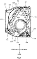
Figure 1] Figure 1 is a vertical sectional side view schematically illustrating a configuration example of an indoor unit for air conditioners according to the present embodiment. - [
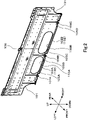
Figure 2] Figure 2 is a perspective view schematically illustrating a configuration example of an installation plate according to the present embodiment. - [
Figure 3] Figure 3 is a front view schematically illustrating a configuration example of the installation plate according to the present embodiment. - [
Figure 4] Figure 4 is an enlarged view schematically illustrating a configuration example of a clamping section and a surrounding part thereof according to the present embodiment. - [
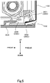
Figure 5] Figure 5 is an enlarged view schematically illustrating a configuration example of a clamped state maintaining section and a surrounding part thereof according to the present embodiment. - Hereinafter, an embodiment related to an indoor unit for air conditioners will be described with reference to the drawings. An
indoor unit 10 for air conditioners illustrated as an example inFigure 1 constitutes an air conditioner along with an outdoor unit, which is provided outdoors and is not illustrated in the drawing, and includes aninstallation plate 100 and anindoor unit 200. Theinstallation plate 100 is made of metal and is strongly fixed to an indoor wall surface with bolts, for example. Theindoor unit 200 is attached to a front surface side, in other words, an indoor side of theinstallation plate 100 fixed to the indoor wall surface with screws and bolts, for example. - Next, a configuration example of the
indoor unit 200 will be described. Theindoor unit 200 includes a unitmain body section 201 and aunit cover section 202. The unitmain body section 201 constitutes a main body section of theindoor unit 200 and is fixed directly to the front surface side of theinstallation plate 100 with screws and bolts, for example. Theunit cover section 202 is configured as a cover section with substantially a box shape covering surfaces on the indoor side of the unitmain body section 201 fixed to the front surface side of theinstallation plate 100, in this case, a front surface, an upper surface, a lower surface, a left side surface, and a right side surface. - An
air inlet port 203 is provided at an upper portion of theindoor unit 200, and anair outlet port 204 is provided at a lower portion of theindoor unit 200. Also, a blowingpassage 205 is provided from theair inlet port 203 to theair outlet port 204 inside theindoor unit 200. Anair filter 206, aheat exchanger 207, across flow fan 208, alouver 209, and the like are provided from an upstream side, which corresponds to the side of theair inlet port 203, toward a downstream side, which corresponds to the side of theair outlet port 204, inside the blowingpassage 205. - The
air filter 206 captures foreign matters included in air suctioned from theair inlet port 203. Theheat exchanger 207 performs heat exchange with the air suctioned from theair inlet port 203 and heats or cools the air. Thecross flow fan 208 suctions indoor air from theair inlet port 203 and forms a flow of the air blown out from theair outlet port 204 to the indoor space through the blowingpassage 205. Thelouver 209 adjusts a direction of the air blown out from theair outlet port 204. - Next, a configuration example of the
installation plate 100 will be described. As illustrated as an example inFigures 2 and3 , theinstallation plate 100 has an elongated substantially rectangular plate shape. In this case, theinstallation plate 100 has a shape with a longer dimension in the left-right direction than the dimension in the vertical direction in a state in which theinstallation plate 100 is fixed to the indoor wall surface.Notch portions 101 into which piping and the like can be inserted are provided at lower portions of both left and right end portions of theinstallation plate 100. Also, alinear section 102 is provided at a lower portion of theinstallation plate 100 at a position between thenotch portions 101 on both the left and right ends. Thelinear section 102 includes a plurality of, in this case, twosub-linear sections - Both the
sub-linear sections sub-linear sections installation plate 100 toward the indoor side. Moreover, distal end portions of thesub-linear sections - A length LA of the
sub-linear section 102A and a length LB of thesub-linear section 102B are different lengths, and in this case, the length LA of thesub-linear section 102A is shorter than the length LB of thesub-linear section 102B. Note that the length LA of thesub-linear section 102A and the length LB of thesub-linear section 102B may be the same length. Also, a total length of the length LA of thesub-linear section 102A and the length LB of thesub-linear section 102B is preferably configured to secure at least a length that is at least 30% or more of the entire length of theinstallation plate 100 in the left-right direction or the entire length of theindoor unit 10 in the left-right direction. - Also, in this case, the
entire sub-linear section 102A is located on the left side beyond a center line CL of theinstallation plate 100 when seen from the front side, which is the indoor side. On the other hand, thesub-linear section 102B is located with the left end side thereof located on the left side beyond the center line CL of theinstallation plate 100 and with the center portion and the right end side thereof except for the left end side located on the right side beyond the center line CL of theinstallation plate 100 when seen from the front side, which is the indoor side. Therefore, theinstallation plate 100 is configured to include at least a part of thelinear section 102 at the center portion thereof in the left-right direction, in this case, the left end part of thesub-linear section 102B. Moreover, theinstallation plate 100 is configured to include theentire sub-linear section 102A and a part of thesub-linear section 102B on the left side beyond the center portion in the left-right direction and include the other portions of thesub-linear section 102B on the right side beyond the center portion in the left-right direction. - Also, the
installation plate 100 includes a plurality of, in this case, two through-hole portions hole portions installation plate 100. Also, the length of the through-hole portion 103A in the left-right direction is shorter than the length of the through-hole portion 103B in the left-right direction. Note that the length of the through-hole portion 103A in the left-right direction and the length of the through-hole portion 103B in the left-right direction may be the same length. Moreover, the length of the through-hole portion 103A in the vertical direction and the length of the through-hole portion 103B in the vertical direction are the same length. Note that the length of the through-hole portion 103A in the vertical direction and the length of the through-hole portion 103B in the vertical direction may be different lengths. - Also, in this case, an opening area of the through-
hole portion 103A is smaller than an opening area of the through-hole portion 103B. Note that the opening area of the through-hole portion 103A and the opening area of the through-hole portion 103B may be the same. In addition, the through-hole portion 103A is located above thesub-linear section 102A. In this case, the center portion of the through-hole portion 103A in the left-right direction substantially or completely conforms to the center portion of thesub-linear section 102A in the left-right direction. Also, the through-hole portion 103B is located above thesub-linear section 102B. In this case, the center portion of the through-hole portion 103B deviates from the center portion of thesub-linear section 102B on the left side by a predetermined amount, and the left end portion of the through-hole portion 103A is located on the left side beyond the left end portion of thesub-linear section 102B. Note that this can be implemented with the amount of deviation between the center portion of the through-hole portion 103B and the center portion of thesub-linear section 102B appropriately changed. - Also, the
installation plate 100 includes a plurality of, in this case, three screw-fastening sections fastening sections main body section 201 constituting the main body section of theindoor unit 200 is strongly fixed with screws, which are not illustrated, via the screw-fastening sections - Also, the screw-
fastening sections installation plate 100. In other words, the screw-fastening sections sub-linear section 102A in the left-right direction. Also, the screw-fastening sections sub-linear section 102B in the left-right direction. Also, the screw-fastening sections linear section 102 in the left-right direction when the entirelinear section 102 is seen. Moreover, the screw-fastening section 104B is included to be located at an intermediate portion of thelinear section 102 in the left-right direction, in this case, between thesub-linear section 102A and thesub-linear section 102B. Note that the screw-fastening section 104B may be included at the center portion of thelinear section 102 in the left-right direction, or may be included on the left side or the right side beyond the center portion of thelinear section 102 in the left-right direction, for example, as long as the screw-fastening section 104B is included at an intermediate portion of thelinear section 102 in the left-right direction. - Also, the
installation plate 100 includes a plurality of, in this case, four narrowedportions portions installation plate 100. In other words, the narrowedportions sub-linear section 102A in the left-right direction. Also, the narrowedportions sub-linear section 102B in the left-right direction. Moreover, the screw-fastening section 104A is included on the left side, which is an outer side beyond the narrowedportion 105A. In addition, the screw-fastening section 104B is included to be located between the narrowedportion 105B and the narrowedportion 105C. Also, the screw-fastening section 104C is included on the right side, which is an outer side beyond the narrowedportion 105D. - The
indoor unit 200 configured as described above further includes clampingsections 300 as illustrated as an example inFigure 1 . Next, a configuration example of the clampingsections 300 will be described. As illustrated as an example inFigure 4 , each clampingsection 300 forms a structure for clamping thelinear section 102 of theinstallation plate 100 in the vertical direction, and in this case, each clampingsection 300 includes anupper clamping section 301 and alower clamping section 302. The plurality of clampingsections 300 are included at lower portions of the rear portion of theindoor unit 200 along theindoor unit 200 in the left-right direction. Note that this can be implemented with the number of clampingsections 300 appropriately changed. Also, this can be implemented with intervals of the plurality of clampingsections 300 appropriately changed. - The
upper clamping section 301 is an example of the first clamping section, and in this case, theupper clamping section 301 is provided to project downward at a lower portion of a rear portion of the unitmain body section 201. In this case, theupper clamping section 301 is provided integrally with a rear portion of a member of the unitmain body section 201 of theindoor unit 200 constituting a rear wall surface of theair outlet port 204. Also, an inclined portion 301a that is linearly inclined to be gradually elevated from the front side toward the rear side is provided at a lower portion of the rear portion of theupper clamping section 301. Note that the inclined portion 301a is not limited to the linear shape and may be inclined in a curved shape, for example. - The
lower clamping section 302 is an example of the second clamping section, and in this case, a rear end portion of a lower surface of theunit cover section 202 functions as thelower clamping section 302. Both the upper surface and the lower surface of thelower clamping section 302 are substantially horizontal planes. - In a state in which the
unit cover section 202 is attached to the unitmain body section 201, theupper clamping section 301 and thelower clamping section 302 face each other in the vertical direction. Also, a clearance is formed by the inclined portion 301a provided between theupper clamping section 301 and thelower clamping section 302. Also, in a state in which theindoor unit 200 is attached to theinstallation plate 100 on the front side, thelinear section 102 of theinstallation plate 100 is pinched between theupper clamping section 301 and thelower clamping section 302. In other words, thelinear section 102 of theinstallation plate 100 is brought into a state in which it is pinched by theclamping section 300 of theindoor unit 200 in the vertical direction. - Also, as illustrated as an example in
Figure 1 , theindoor unit 200 further includes clampedstate maintaining sections 400. As illustrated as an example inFigure 5 , each clampedstate maintaining section 400 is included on the front side beyond theclamping section 300 in this case. Also, the plurality of clampedstate maintaining sections 400 are included at lower portions of the rear portion of theindoor unit 200 along theindoor unit 200 in the left-right direction. Note that this can be implemented with the number of clampedstate maintaining sections 400 appropriately changed in accordance with the number of clampingsections 300, for example. Also, this can be implemented with intervals of the plurality of clampedstate maintaining sections 400 appropriately changed in accordance with the intervals of the plurality of clampingsections 300, for example. The clampedstate maintaining sections 400 are preferably provided in the vicinity of the clampingsections 300. Also, the number and the intervals of the clampedstate maintaining sections 400 may be the same as or different from the number and the intervals of the clampingsections 300. - Each clamped
state maintaining section 400 includes aclaw hole portion 401 provided on the side of the unitmain body section 201 and aclaw portion 402 provided on the side of theunit cover section 202. In this case, theclaw hole portion 401 is provided integrally with the rear portion of the member of the unitmain body section 201 of theindoor unit 200 constituting the rear wall surface of theair outlet port 204. Also, theclaw hole portion 401 is a rectangular hole portion opened on the front side in the front-back direction. Theclaw portion 402 is provided integrally with an upper surface of the rear end portion of the lower surface of theunit cover section 202. In addition, theclaw portion 402 is a claw portion linear extending on the rear side in the front-back direction. - In a state in which the
unit cover section 202 is attached to the unitmain body section 201, theclaw portion 402 is inserted into theclaw hole portion 401 from the front side toward the rear side. In this manner, the rear end portion of the lower surface of theunit cover section 202, that is, a part where thelower clamping section 302 is provided is strongly fixed to the lower portion of the rear portion of the unitmain body section 201, that is, a part where theupper clamping section 301 is provided. It is thus possible to stably maintain the state in which theupper clamping section 301 and thelower clamping section 302 face each other in the vertical direction and thus to stably maintain the state in which thelinear section 102 of theinstallation plate 100 is clamped with theupper clamping section 301 and thelower clamping section 302 in the vertical direction. - According to the
indoor unit 10 for air conditioners according to the present embodiment, theindoor unit 200 is configured to clamp thelinear section 102 of theinstallation plate 100 with theupper clamping section 301 and thelower clamping section 302 of theclamping section 300 in the vertical direction. With this configuration, it is possible to suppress an upward force with thelinear section 102 by thelower clamping section 302 abutting on the lower surface of thelinear section 102 in a case in which the upward force acts on theindoor unit 200. On the other hand, in a case in which a downward force acts on theindoor unit 200, it is possible to suppress the downward force with thelinear section 102 by theupper clamping section 301 abutting on the upper surface of thelinear section 102. Therefore, it is possible to sufficiently curb deformation and distortion of the lower surface of theunit cover section 202 and to improve an appearance not only in a case in which the upward force acts on theindoor unit 200 but also in a case in which the downward force acts on theindoor unit 200. - Also, according to the
indoor unit 10, thelinear section 102 is included at least at the center portion of theinstallation plate 100 in the left-right direction. With this configuration, it is possible to sufficiently curb occurrence of deformation and distortion at the center portion of theindoor unit 200 in the left-right direction where deformation and distortion of the lower surface of theunit cover section 202 are likely to occur. - Also, according to the
indoor unit 10, thelinear sections 102 are further included both on the left side and on the right side of the center portion of theinstallation plate 100 in the left-right direction. With this configuration, it is possible to sufficiently curb occurrence of deformation and distortion not only at the center portion of the lower surface of theunit cover section 202 in the left-right direction but also in a wide range including the left side and the right side thereof. - Also, according to the
indoor unit 10, theinstallation plate 100 includes, in a dispersed manner, the screw-fastening sections linear section 102 and the end portions of thelinear section 102 in the left-right direction. With this configuration, it is possible to attach theindoor unit 200 to theinstallation plate 100 at an accurate position by performing screwing at the plurality of screw-fastening sections unit cover section 202 at a further accurate position relative to theinstallation plate 100 and thus to further curb occurrence of deformation and distortion of the appearance of theindoor unit 10. - Also, according to the
indoor unit 10, theinstallation plate 100 includes, in a dispersed manner, the narrowedportions linear section 102 in the left-right direction. With this configuration, it is possible to improve strength of thelinear section 102 and a part in the vicinity thereof and to sufficiently curb occurrence of deformation and distortion of thelinear section 102 and thus occurrence of deformation and distortion of the appearance of theindoor unit 10. - Also, according to the
indoor unit 10, the clampedstate maintaining section 400 that maintains the state in which thelinear section 102 is clamped with theupper clamping section 301 and thelower clamping section 302 in the vertical direction is included. With this configuration, it is possible to stably maintain the state in which thelinear section 102 of theinstallation plate 100 is clamped with theclamping section 300 in the vertical direction and to further effectively curb occurrence of deformation and distortion of the appearance of theindoor unit 200. - Also, it is possible to stably maintain, with the clamped
state maintaining section 400, the state in which theupper clamping section 301 and thelower clamping section 302 face each other in the vertical direction and thus the state in which thelinear section 102 of theinstallation plate 100 is clamped with theupper clamping section 301 and thelower clamping section 302 even with the configuration in which theupper clamping section 301 is provided on the side of the unitmain body section 201 and thelower clamping section 302 is provided on the side of theunit cover section 202, that is, with the configuration in which theupper clamping section 301 and thelower clamping section 302 are provided in mutually different members. Therefore, it is possible to further effectively curb occurrence of deformation and distortion of the appearance of theindoor unit 200. - Note that the present embodiment is not limited to the aforementioned embodiment, and various modifications and expansions can be made without departing from the gist thereof.
- For example, the number of sub-linear sections constituting the
linear section 102 is not limited to two and may be one or another plural number like three or more. Also, this can be implemented with the projection length and the inclination angle of thelinear section 102 from the lower side of theinstallation plate 100 appropriately changed. Moreover, the plurality of sub-linear sections may have mutually the same projection length and the same inclination angle or may have different projection lengths and different inclination angles. - In addition, although the
linear section 102 is preferably included at least at the center portion of theinstallation plate 100 in the left-right direction, theindoor unit 200 may be configured not to include thelinear section 102 at the center portion of theinstallation plate 100 in the left-right direction. Also, thelinear section 102 may be configured to be included on any one side of the left part and the right part of the center portion of theinstallation plate 100 in the left-right direction. - In addition, the number of screw-fastening sections is not limited to three and may be one, two, or another plural number like four or more. Also, the numbers of screw-fastening sections may be the same or different on the left side and the right side of the
installation plate 100. Moreover, the plurality of screw-fastening sections may have mutually the same shape and the same size or may have different shapes and different sizes. - Also, the number of narrowed portions is not limited to four and may be one, two, three, or another plural number like five or more. In addition, the numbers of narrowed portions may be the same or different at the left part and the right part of the center portion of the
installation plate 100 in the left-right direction. Also, the plurality of narrowed portions may have mutually the same shape and the same size or may have different shapes and different sizes. In addition, the narrowed portions may be provided at both end portions of thelinear section 102 in the left-right direction or may be provided only on one end side. - In addition, the clamped
state maintaining section 400 may be configured such that theclaw hole portion 401 is provided on the side of theunit cover section 202 and theclaw portion 402 is provided on the side of the unitmain body section 201. Also, the clamped state maintaining section is not limited to the configuration including theclaw hole portion 401 and theclaw portion 402, and it is possible to apply various configurations as long as the configurations enable the state in which thelinear section 102 is clamped with theupper clamping section 301 and thelower clamping section 302 in the vertical direction to be maintained, such as pins and pin holes, for example. - Although the embodiment of the present invention has been described above, the present embodiment has been presented as an example and is not intended to limit the scope of the present invention. The novel embodiment can be implemented in various other forms, and various omissions, replacements, amendments can be made without departing from the gist of the present invention. The present embodiment and modifications thereof are included within the scope and the gist of the present invention and are also included in the inventions described in the claims and a scope equivalent thereto.
Claims (6)
- An indoor unit for air conditioners including:an installation plate that is secured to an indoor wall surface; andan indoor unit that is attached to the installation plate,wherein the installation plate includes a linear section projecting on an indoor side and linearly extending in a horizontal direction, andthe indoor unit includes a clamping section that clamps the linear section in a vertical direction.
- The indoor unit for air conditioners according to claim 1, wherein the linear section is included at least at a center portion of the installation plate in a left-right direction.
- The indoor unit for air conditioners according to claim 2, wherein the linear section is further included on a left side and a right side of the center portion of the installation plate in the left-right direction.
- The indoor unit for air conditioners according to any one of claims 1 to 3,wherein the installation plate includes screw-fastening sections that screw-fasten the indoor unit, andthe screw-fastening sections are included at an intermediate portion of the linear section and end portions of the linear section in the left-right direction.
- The indoor unit for air conditioners according to any one of claims 1 to 4, wherein the installation plate includes narrowed portions at the end portions of the linear section in the left-right direction.
- The indoor unit for air conditioners according to any one of claims 1 to 5,wherein the indoor unit includesa unit main body section that is secured to the installation plate, anda unit cover section that covers a surface of the unit main body section on the indoor side,the clamping section includesa first clamping section that is provided at the unit main body section, anda second clamping section that is provided at the unit cover section, andthe indoor unit comprises: a clamped state maintaining section that maintains a state in which the linear section is clamped with the first clamping section and the second clamping section in the vertical direction.
Applications Claiming Priority (1)
| Application Number | Priority Date | Filing Date | Title |
|---|---|---|---|
| PCT/JP2019/024733 WO2020255380A1 (en) | 2019-06-21 | 2019-06-21 | Indoor unit for air conditioners |
Publications (3)
| Publication Number | Publication Date |
|---|---|
| EP3988857A1 true EP3988857A1 (en) | 2022-04-27 |
| EP3988857A4 EP3988857A4 (en) | 2023-01-11 |
| EP3988857B1 EP3988857B1 (en) | 2025-03-26 |
Family
ID=74040287
Family Applications (1)
| Application Number | Title | Priority Date | Filing Date |
|---|---|---|---|
| EP19933348.5A Active EP3988857B1 (en) | 2019-06-21 | 2019-06-21 | Indoor unit for air conditioners |
Country Status (4)
| Country | Link |
|---|---|
| EP (1) | EP3988857B1 (en) |
| JP (1) | JP7209087B2 (en) |
| CN (1) | CN114008390B (en) |
| WO (1) | WO2020255380A1 (en) |
Family Cites Families (11)
| Publication number | Priority date | Publication date | Assignee | Title |
|---|---|---|---|---|
| JPS6118342Y2 (en) * | 1980-03-04 | 1986-06-04 | ||
| JPS6118431U (en) * | 1984-07-09 | 1986-02-03 | 株式会社東芝 | Air conditioner indoor unit installation structure |
| JPH05312349A (en) * | 1992-05-12 | 1993-11-22 | Mitsubishi Electric Corp | Installation device for air-conditioner |
| JP3071353B2 (en) * | 1994-01-18 | 2000-07-31 | 東芝キヤリア株式会社 | Indoor unit of air conditioner |
| JPH09324927A (en) * | 1996-06-06 | 1997-12-16 | Fujitsu General Ltd | Air conditioner installation equipment |
| JP3122715B2 (en) * | 1996-11-13 | 2001-01-09 | 東芝キヤリア株式会社 | Indoor unit of air conditioner |
| JP3879432B2 (en) * | 2000-04-24 | 2007-02-14 | 松下電器産業株式会社 | Air conditioner installation equipment |
| DE202004015275U1 (en) * | 2004-09-17 | 2005-05-04 | Hdm Gmbh | Panel, in particular, floor panel comprises a tongue section which carries or interacts with a locking element and has a greater elasticity than the locking element |
| JP5264680B2 (en) | 2009-11-12 | 2013-08-14 | 三菱電機株式会社 | Indoor unit and air conditioner |
| CN203364249U (en) * | 2013-01-27 | 2013-12-25 | 宁波奥克斯空调有限公司 | Casing structure of indoor unit of wall-mounted air conditioner |
| WO2018185842A1 (en) | 2017-04-04 | 2018-10-11 | 三菱電機株式会社 | Indoor unit for air conditioner |
-
2019
- 2019-06-21 CN CN201980097592.4A patent/CN114008390B/en active Active
- 2019-06-21 EP EP19933348.5A patent/EP3988857B1/en active Active
- 2019-06-21 WO PCT/JP2019/024733 patent/WO2020255380A1/en not_active Ceased
- 2019-06-21 JP JP2021528600A patent/JP7209087B2/en active Active
Also Published As
| Publication number | Publication date |
|---|---|
| WO2020255380A1 (en) | 2020-12-24 |
| CN114008390A (en) | 2022-02-01 |
| JPWO2020255380A1 (en) | 2020-12-24 |
| JP7209087B2 (en) | 2023-01-19 |
| EP3988857A4 (en) | 2023-01-11 |
| EP3988857B1 (en) | 2025-03-26 |
| CN114008390B (en) | 2023-04-28 |
Similar Documents
| Publication | Publication Date | Title |
|---|---|---|
| EP2952822B1 (en) | Outdoor unit for air-conditioning apparatus | |
| US11162693B2 (en) | Fan unit, and outdoor unit of air conditioner comprising fan unit | |
| US20200158373A1 (en) | Air conditioning indoor unit | |
| WO2018107867A1 (en) | Air outlet assembly, air conditioner and vehicle | |
| US10240805B2 (en) | Indoor unit for air conditioner | |
| US20100206514A1 (en) | Air conditioner indoor unit | |
| EP3988857B1 (en) | Indoor unit for air conditioners | |
| US11370274B2 (en) | Blow-off device of air conditioner | |
| US6685556B1 (en) | Automatic modular outlets for conditioned air, dampers, and modular return air grills | |
| CN203869173U (en) | Air conditioner | |
| KR200387015Y1 (en) | Air guider for condensing unit of air conditioner | |
| JP5790621B2 (en) | Air conditioning indoor unit | |
| EP3339763A1 (en) | Indoor unit of air conditioner | |
| WO2018185842A1 (en) | Indoor unit for air conditioner | |
| JP3608182B2 (en) | Line-type outlet | |
| EP3130860A1 (en) | Air conditioner | |
| JP2009058206A (en) | Air conditioner indoor unit | |
| JP7241918B2 (en) | Indoor unit of air conditioner | |
| US20040157543A1 (en) | Automatic modular outlets for conditioned air, dampers, and modular return air grills | |
| CN104094065B (en) | The indoor set of aircondition | |
| CN222378227U (en) | Pipeline machine | |
| KR20100001506A (en) | Air conditioner | |
| JP2010216750A (en) | Air conditioner | |
| EP3517852A1 (en) | Diffuser for air conditioning installations | |
| CN208765216U (en) | A left side plate matched with a long-short-expansion-high condenser, an outdoor unit and an air conditioner |
Legal Events
| Date | Code | Title | Description |
|---|---|---|---|
| STAA | Information on the status of an ep patent application or granted ep patent |
Free format text: STATUS: THE INTERNATIONAL PUBLICATION HAS BEEN MADE |
|
| PUAI | Public reference made under article 153(3) epc to a published international application that has entered the european phase |
Free format text: ORIGINAL CODE: 0009012 |
|
| STAA | Information on the status of an ep patent application or granted ep patent |
Free format text: STATUS: REQUEST FOR EXAMINATION WAS MADE |
|
| 17P | Request for examination filed |
Effective date: 20211217 |
|
| AK | Designated contracting states |
Kind code of ref document: A1 Designated state(s): AL AT BE BG CH CY CZ DE DK EE ES FI FR GB GR HR HU IE IS IT LI LT LU LV MC MK MT NL NO PL PT RO RS SE SI SK SM TR |
|
| DAV | Request for validation of the european patent (deleted) | ||
| DAX | Request for extension of the european patent (deleted) | ||
| A4 | Supplementary search report drawn up and despatched |
Effective date: 20221209 |
|
| RIC1 | Information provided on ipc code assigned before grant |
Ipc: F24F 13/20 20060101AFI20221205BHEP |
|
| GRAP | Despatch of communication of intention to grant a patent |
Free format text: ORIGINAL CODE: EPIDOSNIGR1 |
|
| STAA | Information on the status of an ep patent application or granted ep patent |
Free format text: STATUS: GRANT OF PATENT IS INTENDED |
|
| INTG | Intention to grant announced |
Effective date: 20241021 |
|
| GRAS | Grant fee paid |
Free format text: ORIGINAL CODE: EPIDOSNIGR3 |
|
| GRAA | (expected) grant |
Free format text: ORIGINAL CODE: 0009210 |
|
| STAA | Information on the status of an ep patent application or granted ep patent |
Free format text: STATUS: THE PATENT HAS BEEN GRANTED |
|
| AK | Designated contracting states |
Kind code of ref document: B1 Designated state(s): AL AT BE BG CH CY CZ DE DK EE ES FI FR GB GR HR HU IE IS IT LI LT LU LV MC MK MT NL NO PL PT RO RS SE SI SK SM TR |
|
| RAP3 | Party data changed (applicant data changed or rights of an application transferred) |
Owner name: CARRIER JAPAN CORPORATION |
|
| REG | Reference to a national code |
Ref country code: GB Ref legal event code: FG4D |
|
| REG | Reference to a national code |
Ref country code: CH Ref legal event code: EP |
|
| REG | Reference to a national code |
Ref country code: DE Ref legal event code: R096 Ref document number: 602019067956 Country of ref document: DE |
|
| REG | Reference to a national code |
Ref country code: IE Ref legal event code: FG4D |
|
| PG25 | Lapsed in a contracting state [announced via postgrant information from national office to epo] |
Ref country code: RS Free format text: LAPSE BECAUSE OF FAILURE TO SUBMIT A TRANSLATION OF THE DESCRIPTION OR TO PAY THE FEE WITHIN THE PRESCRIBED TIME-LIMIT Effective date: 20250626 |
|
| PG25 | Lapsed in a contracting state [announced via postgrant information from national office to epo] |
Ref country code: FI Free format text: LAPSE BECAUSE OF FAILURE TO SUBMIT A TRANSLATION OF THE DESCRIPTION OR TO PAY THE FEE WITHIN THE PRESCRIBED TIME-LIMIT Effective date: 20250326 |
|
| PGFP | Annual fee paid to national office [announced via postgrant information from national office to epo] |
Ref country code: DE Payment date: 20250612 Year of fee payment: 7 |
|
| PGFP | Annual fee paid to national office [announced via postgrant information from national office to epo] |
Ref country code: GB Payment date: 20250620 Year of fee payment: 7 |
|
| REG | Reference to a national code |
Ref country code: LT Ref legal event code: MG9D |
|
| PG25 | Lapsed in a contracting state [announced via postgrant information from national office to epo] |
Ref country code: NO Free format text: LAPSE BECAUSE OF FAILURE TO SUBMIT A TRANSLATION OF THE DESCRIPTION OR TO PAY THE FEE WITHIN THE PRESCRIBED TIME-LIMIT Effective date: 20250626 |
|
| PG25 | Lapsed in a contracting state [announced via postgrant information from national office to epo] |
Ref country code: HR Free format text: LAPSE BECAUSE OF FAILURE TO SUBMIT A TRANSLATION OF THE DESCRIPTION OR TO PAY THE FEE WITHIN THE PRESCRIBED TIME-LIMIT Effective date: 20250326 |
|
| PG25 | Lapsed in a contracting state [announced via postgrant information from national office to epo] |
Ref country code: LV Free format text: LAPSE BECAUSE OF FAILURE TO SUBMIT A TRANSLATION OF THE DESCRIPTION OR TO PAY THE FEE WITHIN THE PRESCRIBED TIME-LIMIT Effective date: 20250326 |
|
| PGFP | Annual fee paid to national office [announced via postgrant information from national office to epo] |
Ref country code: FR Payment date: 20250627 Year of fee payment: 7 |
|
| PG25 | Lapsed in a contracting state [announced via postgrant information from national office to epo] |
Ref country code: GR Free format text: LAPSE BECAUSE OF FAILURE TO SUBMIT A TRANSLATION OF THE DESCRIPTION OR TO PAY THE FEE WITHIN THE PRESCRIBED TIME-LIMIT Effective date: 20250627 Ref country code: BG Free format text: LAPSE BECAUSE OF FAILURE TO SUBMIT A TRANSLATION OF THE DESCRIPTION OR TO PAY THE FEE WITHIN THE PRESCRIBED TIME-LIMIT Effective date: 20250326 |
|
| REG | Reference to a national code |
Ref country code: NL Ref legal event code: MP Effective date: 20250326 |
|
| PG25 | Lapsed in a contracting state [announced via postgrant information from national office to epo] |
Ref country code: NL Free format text: LAPSE BECAUSE OF FAILURE TO SUBMIT A TRANSLATION OF THE DESCRIPTION OR TO PAY THE FEE WITHIN THE PRESCRIBED TIME-LIMIT Effective date: 20250326 |
|
| PG25 | Lapsed in a contracting state [announced via postgrant information from national office to epo] |
Ref country code: SE Free format text: LAPSE BECAUSE OF FAILURE TO SUBMIT A TRANSLATION OF THE DESCRIPTION OR TO PAY THE FEE WITHIN THE PRESCRIBED TIME-LIMIT Effective date: 20250326 |
|
| REG | Reference to a national code |
Ref country code: AT Ref legal event code: MK05 Ref document number: 1779308 Country of ref document: AT Kind code of ref document: T Effective date: 20250326 |
|
| PG25 | Lapsed in a contracting state [announced via postgrant information from national office to epo] |
Ref country code: SM Free format text: LAPSE BECAUSE OF FAILURE TO SUBMIT A TRANSLATION OF THE DESCRIPTION OR TO PAY THE FEE WITHIN THE PRESCRIBED TIME-LIMIT Effective date: 20250326 |
|
| PG25 | Lapsed in a contracting state [announced via postgrant information from national office to epo] |
Ref country code: ES Free format text: LAPSE BECAUSE OF FAILURE TO SUBMIT A TRANSLATION OF THE DESCRIPTION OR TO PAY THE FEE WITHIN THE PRESCRIBED TIME-LIMIT Effective date: 20250326 Ref country code: PT Free format text: LAPSE BECAUSE OF FAILURE TO SUBMIT A TRANSLATION OF THE DESCRIPTION OR TO PAY THE FEE WITHIN THE PRESCRIBED TIME-LIMIT Effective date: 20250728 |
|
| PG25 | Lapsed in a contracting state [announced via postgrant information from national office to epo] |
Ref country code: IT Free format text: LAPSE BECAUSE OF FAILURE TO SUBMIT A TRANSLATION OF THE DESCRIPTION OR TO PAY THE FEE WITHIN THE PRESCRIBED TIME-LIMIT Effective date: 20250326 Ref country code: PL Free format text: LAPSE BECAUSE OF FAILURE TO SUBMIT A TRANSLATION OF THE DESCRIPTION OR TO PAY THE FEE WITHIN THE PRESCRIBED TIME-LIMIT Effective date: 20250326 |
|
| PG25 | Lapsed in a contracting state [announced via postgrant information from national office to epo] |
Ref country code: AT Free format text: LAPSE BECAUSE OF FAILURE TO SUBMIT A TRANSLATION OF THE DESCRIPTION OR TO PAY THE FEE WITHIN THE PRESCRIBED TIME-LIMIT Effective date: 20250326 |
|
| PG25 | Lapsed in a contracting state [announced via postgrant information from national office to epo] |
Ref country code: EE Free format text: LAPSE BECAUSE OF FAILURE TO SUBMIT A TRANSLATION OF THE DESCRIPTION OR TO PAY THE FEE WITHIN THE PRESCRIBED TIME-LIMIT Effective date: 20250326 |
|
| PG25 | Lapsed in a contracting state [announced via postgrant information from national office to epo] |
Ref country code: RO Free format text: LAPSE BECAUSE OF FAILURE TO SUBMIT A TRANSLATION OF THE DESCRIPTION OR TO PAY THE FEE WITHIN THE PRESCRIBED TIME-LIMIT Effective date: 20250326 |
|
| PG25 | Lapsed in a contracting state [announced via postgrant information from national office to epo] |
Ref country code: SK Free format text: LAPSE BECAUSE OF FAILURE TO SUBMIT A TRANSLATION OF THE DESCRIPTION OR TO PAY THE FEE WITHIN THE PRESCRIBED TIME-LIMIT Effective date: 20250326 |
|
| PG25 | Lapsed in a contracting state [announced via postgrant information from national office to epo] |
Ref country code: IS Free format text: LAPSE BECAUSE OF FAILURE TO SUBMIT A TRANSLATION OF THE DESCRIPTION OR TO PAY THE FEE WITHIN THE PRESCRIBED TIME-LIMIT Effective date: 20250726 |
|
| REG | Reference to a national code |
Ref country code: DE Ref legal event code: R097 Ref document number: 602019067956 Country of ref document: DE |
|
| PG25 | Lapsed in a contracting state [announced via postgrant information from national office to epo] |
Ref country code: DK Free format text: LAPSE BECAUSE OF FAILURE TO SUBMIT A TRANSLATION OF THE DESCRIPTION OR TO PAY THE FEE WITHIN THE PRESCRIBED TIME-LIMIT Effective date: 20250326 |
|
| PG25 | Lapsed in a contracting state [announced via postgrant information from national office to epo] |
Ref country code: CZ Free format text: LAPSE BECAUSE OF FAILURE TO SUBMIT A TRANSLATION OF THE DESCRIPTION OR TO PAY THE FEE WITHIN THE PRESCRIBED TIME-LIMIT Effective date: 20250326 |
|
| REG | Reference to a national code |
Ref country code: CH Ref legal event code: H13 Free format text: ST27 STATUS EVENT CODE: U-0-0-H10-H13 (AS PROVIDED BY THE NATIONAL OFFICE) Effective date: 20260127 |
|
| PG25 | Lapsed in a contracting state [announced via postgrant information from national office to epo] |
Ref country code: MC Free format text: LAPSE BECAUSE OF FAILURE TO SUBMIT A TRANSLATION OF THE DESCRIPTION OR TO PAY THE FEE WITHIN THE PRESCRIBED TIME-LIMIT Effective date: 20250326 |
|
| PLBE | No opposition filed within time limit |
Free format text: ORIGINAL CODE: 0009261 |
|
| STAA | Information on the status of an ep patent application or granted ep patent |
Free format text: STATUS: NO OPPOSITION FILED WITHIN TIME LIMIT |
|
| REG | Reference to a national code |
Ref country code: CH Ref legal event code: L10 Free format text: ST27 STATUS EVENT CODE: U-0-0-L10-L00 (AS PROVIDED BY THE NATIONAL OFFICE) Effective date: 20260211 |
|
| PG25 | Lapsed in a contracting state [announced via postgrant information from national office to epo] |
Ref country code: LU Free format text: LAPSE BECAUSE OF NON-PAYMENT OF DUE FEES Effective date: 20250621 |
|
| REG | Reference to a national code |
Ref country code: BE Ref legal event code: MM Effective date: 20250630 |
|
| 26N | No opposition filed |
Effective date: 20260105 |
|
| PG25 | Lapsed in a contracting state [announced via postgrant information from national office to epo] |
Ref country code: IE Free format text: LAPSE BECAUSE OF NON-PAYMENT OF DUE FEES Effective date: 20250621 |
|
| PG25 | Lapsed in a contracting state [announced via postgrant information from national office to epo] |
Ref country code: BE Free format text: LAPSE BECAUSE OF NON-PAYMENT OF DUE FEES Effective date: 20250630 |
|
| PG25 | Lapsed in a contracting state [announced via postgrant information from national office to epo] |
Ref country code: CH Free format text: LAPSE BECAUSE OF NON-PAYMENT OF DUE FEES Effective date: 20250630 |