EP3988742A1 - Rosette-less window or door handle - Google Patents
Rosette-less window or door handle Download PDFInfo
- Publication number
- EP3988742A1 EP3988742A1 EP21203723.8A EP21203723A EP3988742A1 EP 3988742 A1 EP3988742 A1 EP 3988742A1 EP 21203723 A EP21203723 A EP 21203723A EP 3988742 A1 EP3988742 A1 EP 3988742A1
- Authority
- EP
- European Patent Office
- Prior art keywords
- handle
- base
- piece
- insert
- recess
- Prior art date
- Legal status (The legal status is an assumption and is not a legal conclusion. Google has not performed a legal analysis and makes no representation as to the accuracy of the status listed.)
- Granted
Links
Images





Classifications
-
- E—FIXED CONSTRUCTIONS
- E05—LOCKS; KEYS; WINDOW OR DOOR FITTINGS; SAFES
- E05B—LOCKS; ACCESSORIES THEREFOR; HANDCUFFS
- E05B3/00—Fastening knobs or handles to lock or latch parts
-
- E—FIXED CONSTRUCTIONS
- E05—LOCKS; KEYS; WINDOW OR DOOR FITTINGS; SAFES
- E05B—LOCKS; ACCESSORIES THEREFOR; HANDCUFFS
- E05B3/00—Fastening knobs or handles to lock or latch parts
- E05B3/003—Fastening knobs or handles to hollow cylindrical spindles, e.g. of tubular locks
-
- E—FIXED CONSTRUCTIONS
- E05—LOCKS; KEYS; WINDOW OR DOOR FITTINGS; SAFES
- E05B—LOCKS; ACCESSORIES THEREFOR; HANDCUFFS
- E05B15/00—Other details of locks; Parts for engagement by bolts of fastening devices
- E05B15/04—Spring arrangements in locks
- E05B2015/0496—Springs actuated by cams or the like
-
- E—FIXED CONSTRUCTIONS
- E05—LOCKS; KEYS; WINDOW OR DOOR FITTINGS; SAFES
- E05B—LOCKS; ACCESSORIES THEREFOR; HANDCUFFS
- E05B65/00—Locks or fastenings for special use
- E05B65/02—Locks or fastenings for special use for thin, hollow, or thin-metal wings
Definitions
- the present invention relates to a rosette-less window or door handle for any type of built-in lock.
- a built-in lock contains a handle with a lever and a spindle which fits in an operating mechanism.
- the handle is rotatably attached in a so-called rosette with which the handle can be attached on the leaf of a window or door by means of screws or the like which are inserted through threaded holes provided to this end in the rosette.
- the operating mechanism ensures the conversion of the rotation of the handle in a translation of a closing lath in the fitting groove, whereby the handle is mounted with a square spindle through a passage in the front wall and with the end of the spindle is coupled with the operating mechanism.
- Such rosette needs to protrude outside the foot of the handle to provide access to said threaded holes of the rosette.
- Such rosette is therefore relatively bulky and affects the aesthetic look of the window or door.
- the purpose of the present invention is to provide a solution to at least one of the aforementioned and other disadvantages.
- the invention relates to a rosette-less handle for attachment to a profile wall of a window or door, and for operating a built-in lock which is slidable along the contour of the leaf of the window or the door via a spindle, whereby the handle comprises a foot and a lever, characterised in that the handle comprises a base piece which can be housed in the foot of the handle, whereby the base piece comprises a base and an insert, whereby with one free end the insert is arranged in a recess of the base and is housed in an open chamber of the foot, and with the other end is blocked against the base, whereby the free end of the foot rests against the base, whereby the insert is provided with an axial recess for a spindle for transmitting the rotational motion of the handle to the operating mechanism of the built-in lock, whereby the insert is attachable in the foot of the handle, whereby the base is attachable to the profile wall via a specific tightening piece also provided with a recess for a
- the base piece comprises a sliding piece which via a central recess is provided over the free end of the insert up against the base, whereby the sliding piece on the side against the base is provided with a wave-shaped pattern of notches and protrusions complementary to the wave-shaped pattern of notches and protrusions around the recess of the base, whereby the sliding piece is provided with semi-circular axial recesses on its outer contour which are complementary to the semi-circular axial guides provided in the foot of the handle.
- the base piece further comprises a cylindrical or conical compression spring over the free end of the insert provided up against the sliding piece.
- the specific tightening piece comprises a central part and a winged part whereby the winged part can be rotated behind the profile wall.
- the central part of the specific tightening piece is provided with a central collar which is complementary and fits in or against the open end or the edge of the insert.
- the specific tightening piece has a complementary shape to the shape of the recess in the profile wall.
- the rotation of the specific tightening piece is 90°.
- the specific tightening piece comprises at least two threaded holes which in the rotated position behind a profile wall align with at least two threaded holes in the profile wall on which the base can be attached using at least two screws in at least two threaded holes.
- the specific tightening piece is premounted in the recess of the profile wall.
- the shape of the specific tightening piece is such that it is unilaterally secured in the recess preventing it from falling into the recess.
- the base of the handle consists of a disk provided on one side with a vertical upstanding edge on the contour within which the free end of the foot of the handle can be arranged.
- the base is provided with an upstanding edge or raised part with a complementary shape to the shape of the recess in the profile wall, such that the upstanding edge or the raised part fits in the recess and it is additionally secured against rotation of the base relative to the profile wall.
- the wave-shaped pattern of the sliding piece and of the base forms a pattern of notches and protrusions per 90° around the contour.
- the insert is cylindrical or conical.
- the insert is provided with an edge with a greater diameter and possibly a slide bearing that can lean against the flat side of the base.
- the free end of the insert is provided with a square cross-section.
- the insert is secured to the handle with a pressing screw which is at an angle in a recess of the handle, whereby the pressing screw engages on a circular sloping surface or a notch of the insert and is thus tightened in the handle.
- the handle as described above is an inner handle.
- the insert can also be secured to the handle via an internal threaded connection and a fixing screw which is premounted in the insert coaxially with the foot of the handle.
- a fixing screw which is premounted in the insert coaxially with the foot of the handle.
- such handle is an outer handle.
- the handle according to the invention can work independently with any type of built-in lock.
- the specific tightening piece can be replaced by a tightening plate provided with two protruding elements with internal thread, whereby the tightening plate is provided via the recess of the operating mechanism or lock.
- the tightening plate can be provided in a known inside door.
- the invention relates more specifically to a rosette-less handle for attachment to a profile wall of a window or door, for operating a built-in lock which is slideable along the contour of the leaf of the window or the door via a spindle, whereby the handle comprises a foot and a lever , whereby the rotational motion of the handle is transferred to an operating mechanism of the built-in lock, whereby the handle comprises a base piece provided with a base, an insert, a sliding piece and a spring, whereby the base consists of a flat disk provided with an upstanding edge within which the free end of the foot of the handle can be provided such that the base piece is housed in the foot of the handle, whereby the base is provided with a recess for an insert, whereby the insert is wider than said recess such that it cannot fall through, whereby the insert is provided with a square cross-section at its free end which fits in the square cross-section of the foot of the handle, whereby the sliding piece over the insert is provided up against the base, whereby a
- the recess in the base is centrally located.
- the shape of the specific tightening piece is such that it fits in a recess of the profile walls and after rotating can be attached behind the profile walls.
- the rotation of the specific tightening piece is 90°.
- the specific tightening piece comprises two threaded holes which in the rotated position behind the profile wall align with two threaded holes in the profile wall to which the base can be attached with two screws.
- the specific tightening piece is premounted in the recess of the profile wall preventing it from falling into the recess.
- the insert is oblong-shaped and on its inside or in its axial core is provided with a recess for a known square spindle for transmitting the rotational motion of the handle to the operating mechanism of the built-in lock.
- the invention also relates to a method for mounting the specific tightening piece in a profile wall, comprising the following steps:
- the invention further relates to a method for the composition of the base piece, comprising the following steps:
- the invention also relates to a method for mounting a base piece to a profile wall, comprising the following steps:
- the invention also relates to a method for mounting a handle via the base piece to a profile wall, comprising the following steps:
- the invention also relates to a method for the spring-loaded operation of a handle, comprising the following steps:
- the invention also relates to a handle for a known inside door whereby the specific tightening piece is replaced by a tightening plate provided with two protruding elements with internal thread, whereby the tightening plate is provided via the recess of the operating mechanism or lock.
- the purpose of the invention is providing a rosette-less window or door handle with spindle drive and built in spring-back mechanism which can work independently with any type of built-in lock.
- the spring mechanism always returns the handle to a horizontal or vertical condition.
- a square spindle the rotational motion can be transmitted to another operating mechanism, such as for example a lock.
- a built-in spring system always returns the handle to its original initial position, even in case of frequent use.
- the spring-loaded handle has a balance position every 90°.
- the handle can be very simply attached to any type of window or door.
- This system allows the handle to be mounted for most profiles.
- Characteristic for a rosette-less handle according to the invention is that the handle no longer has a plate to which it is attached.
- the handle consists of a very small base compared to a long plate of a standard handle.
- the handle according to the invention has several advantages, as described below.
- the rosette-less handle according to the invention can be used for window and door levers whereby a square of 7.8mm and 9mm is possible.
- the rosette-less handle has a click position every 90°, which can be used for windows and pentalock.
- the rosette-less handle is applicable without special square spindle.
- the handle is secure on the outside because it cannot be disassembled from the outside due to the screw that is completely hidden in the insert.
- mounting screw of the inner handle is at an angle such that it is not visible within the normal field of vision.
- the base with the profile provides a very strong connection due to the big overlap of the tightening piece with the profile.
- the rosette-less handle can be simply mounted on site (base piece and handle). Consequently, the door and window profiles can be transported without handles and they do not cause any damage during transport either. Moreover, the window and door profiles can be transported closer to or on each other.
- the handle is easy to disassemble in mounted doors or windows.
- Disassembly of the outer handle is only possible after disassembly of the inner handle.
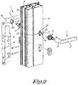
- Figures 1 and 2 show the section of a leaf of a door profile 2 provided with a rosette-less handle 1 according to the invention.
- the handle 1 operates a lock 3 for opening or closing the relevant door.
- the handle 1 according to the invention also applies to a window profile.
- the profile 2 is provided with an inner wall 4 and an outer wall 5 between which the operating mechanism 6 is located.
- a rosette-less handle 1 is mounted, i.e. an inner handle 1 on the inner wall 4 and an outer handle 1 on the outer wall 5.
- the handle 1 consists of a lever 7 with a foot 8.
- An open chamber 10 is provided in the foot 8 of the lever 7 in which a base piece 9 according to the invention can be housed.
- the handle 1 is mounted on the base 14 of the base piece 9 and is provided for receiving a square spindle 11 through a passage in the profile wall 4,5. To this end, the handle is internally provided with a complementary square cross-section 40.
- a recess 12 is provided in the walls 4,5 for attaching the handle 1.
- the recess is located on the surface of the wall and is directly accessible without disassembly of the operating mechanism or the lock.
- Figure 3 shows an inner handle (3A) and an outer handle (3B) according to the invention.
- the base piece 9 is different for an inner handle and an outer handle, more specifically concerning the end with which the base piece 9 is attached to the handle 1.
- the base piece 9 is attached to a specific tightening piece 13. The function thereof is explained below.
- Figure 3C shows a cross-section of the open chamber 10. Said chamber has a specific shape as explained below.
- Figures 4 and 5 show a base piece 9 for an inner handle and an outer handle respectively, whereby the handle 1 is mounted on an inner wall 4 or outer wall 5 of a door respectively.
- the relevant figures show a base piece 9 attached to a specific tightening piece 13.
- the inner and outer handle are largely identical, only the attachment of the handle is different.
- the handle 1 comprises a base piece 9 comprising a base 14, an insert 15, a sliding piece 16, a spring 17 and a locking washer 18.
- the foot 8 of the handle 1 is placed on the base 14 whereby the base piece 9 is housed in the open chamber 10 of the foot 8.
- the base piece 9 is attached by means of a specific tightening piece 13 on the profile wall 4,5 via the base 14.
- the specific tightening piece 13 comprises a central collar 19 and a specific shape which allows it to be secured behind a wall after rotation in a specific recess 12 in the relevant wall.
- the shape of the recess 12 in the wall is complementary to the shape of the specific tightening piece 13.
- the central collar 19 fits in the recess on the underside of the base 14.
- the spacing up to this open end depends on the wall thickness of the profile on which the clamping is carried out.
- the collar is intended to fit in the round section of the recess such that the 90° rotation occurs in a simple and centred way.
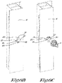
- the specific tightening piece 13 comprises two threaded holes 20 which in the secure position behind the wall align with two threaded holes 21 in the wall. This is shown in detail in figures 6A , 6B and 6C .
- Figure 6A shows the position of the specific tightening piece 13 just before it is placed in the recess 12 of the wall.
- Figure 6B shows the specific tightening piece 13 that is placed in the recess 12 of the wall. Only the central collar 19 still protrudes from the surface of the wall. The cropping of the recess 12 is complementary to the contour of the specific tightening piece 13.
- the base 14 consists of a flat disk 22, circular here, with a vertical upstanding edge 23 of approximately 90° on its contour oriented toward one side of the disk.
- the other side of the disk 22 is flat such that it connects to a flat profile wall.
- the inner contour of the upstanding edge 23 is slightly bigger than the contour of the circular foot 8 of the handle 1.
- the flat disk 22 of the base 14 is provided with recesses for, among others, threaded holes 24 in which screws 25 fit.
- the base 14 also has a specific shape which further fills the recess in the profile. This results in an additional security against rotation.
- the two threaded holes 24 are located at 180° relative to the central axis for attaching the base 14 in the complementary threaded holes 20 of the specific tightening piece 13.
- the base 14 is provided with a central recess 26 for the insert 15.
- the shape of the recess 26 is complementary to the shape of the insert 15.
- the recess 26 is circular and formed as the bearing for rotation.
- the recess 26 also ensures the collar 19 of the specific tightening piece 13 is hidden.
- the base 14 is provided with an upstanding edge 27 in a specific shape of a wave-shaped pattern. This shape is complementary to the shape of the wave-shaped underside of the sliding piece 16.
- the sliding piece 16 is not flat on the underside but provided with a wave-shaped pattern 28 of notches and protrusions which is complementary to the wave-shaped pattern of notches and protrusions of the upstanding edge 27 around the recess 26 of the base 14 as described above.
- the sliding piece 16 is conical and on its outer contour is provided with semi-circular recesses 29 parallel to the direction of the central axis of the base piece 9. They are complementary to the semi-circular guides 30 provided in the foot 8 of the handle 1 ( figure 3C ).
- the sliding piece 16 is further provided with a central recess 31 for the insert (15).
- the shape of the recess 31 is complementary to the shape of the cross-section of the insert 15.
- the insert 15 fits in the central recess 26 of the base 14.
- the insert 15 is further provided with a protruding edge 32 which finds support against the flat side of the base.
- a washer 33 acting as slide bearing, can optionally provide extra support and prevent the insert 15 from being slid through the recess 26 of the base.
- the slide bearing 33 is a plastic slide bearing and limits the wear and tear upon rotation.
- the base of the insert 15 is cylindrical and has a square cross-section at its free end 34.
- the insert 15 can have several specific embodiments at its free end 34 for attaching the handle 1 to the base piece 9.
- said attachment is different for example. It differs in that the inner handle can be disassembled via the handle itself.
- the outer handle can only be disassembled by removing the whole base piece.
- a notch 35 or a sloping surface is provided in which or against which the end of a pressing screw 36 fits.
- the free end 34 of the insert 15 is provided with a hole for a screw 37 and the handle is provided with thread.
- the sunken head 38 of the screw 37 is provided on the inside of the insert 15.
- the handle 1 is provided for receiving the square end of the insert 15. To this end, the handle is internally provided with a complementary square cross-section 40.
- Figure 3C also shows the threaded hole 41 provided in the handle 1 for tightening the screw 37 of the insert.
- the mounting of the base piece 9 according to the invention is simple and as follows.
- the insert 15 is placed with its free end 34 in the recess 26 of the base 14 with the protruding edge 32 against the flat side of the base 14.
- the sliding piece 16 is slid over the insert 15 via the free end 34 of the insert.
- the wave-shaped pattern 28 of the sliding piece 16 is hereby positioned in the corresponding wave-shaped pattern 27 of the base 14.
- a spring 4 is provided over the insert 15 up against the sliding piece 16 after which it is clamped via a locking washer 3.
- a screw 38 with sunken head inside the free end 34 of the insert 15 is subsequently provided for the base piece 9 of an outer handle.
- the base piece 9 is attached to the profile wall as follows.
- the specific tightening piece 13 is attached in the profile wall 4,5 and rotated 90° such that the threaded holes of the specific tightening piece correspond with the holes in the profile wall. After aligning the threaded holes 24 of the base 14 with the threaded holes 20 of the specific tightening piece 13 the base piece 9 is screwed on the tightening piece 13 via two screws 25.
- the shape of the specific tightening piece 13 is such that it fits in the recess 12 of the walls 4,5 and after rotation of the specific tightening piece 13 can be rotated behind the walls 4,5 of the profile 2 and attached therewith.
- the specific tightening piece 13 has an elongated shape.
- the recess 12 in the wall has the same or a complementary shape.
- the shape of the recess 12 is such that the specific tightening piece 13 can be integrated in the recess 12 and thereafter finds support behind the wall after rotation.
- the specific tightening piece 13 can be premounted in a recess 12 in the profile wall 4,5, preventing it from falling into the recess 12.
- the base 14 After rotating the specific tightening piece 13 90°, the base 14 can be attached to the profile 2 by means of two small screws 25.
- This system allows the handle to be mounted for most profiles.
- an adapted shape of the specific tightening piece 13 can be provided, such that it can be attached behind the walls 4,5 of the profile 2.
- the upstanding edge or the raised part 49 of the base 14 in turn falls in the recess 12 in the profile wall 4,5 provided for inserting the specific tightening piece 13, such that an extra security and strong connection against rotation of the base 14 is obtained.
- the upstanding edge or the raised part 49 has a complementary shape to the shape of the recess 12 in the profile wall 4,5.
- the specific tightening piece 13 engages a long way behind the profile 2.
- the strong overlap creates a strong connection against tensile forces perpendicular to the door plane.
- the recess 12 of the profile can leave sufficient space for clearance such that the operation is less critical.
- a variation in thickness can also be absorbed.
- Each tightening piece 13 has a thickness range for a wall thickness of 1.8mm to 2.4mm for example. For thicker profile walls, another tightening piece is necessary.
- the handle 1 is attached to the base piece 9 as follows.
- a standard square spindle 11 is slid in the insert 15.
- the handle 1 can be slid over the base piece 9 and more specifically over the insert 15.
- the free end of the foot 8 of the handle 1 is placed on the base 14 whereby the base piece 9 is housed in the open chamber 10 of the foot 8.
- the free end of the foot 8 and base 14 have a complementary circular shape.
- the open chamber 10 of the handle 1 has a square-shaped cross-section 40 over a certain length in the deepest part of the chamber. Said square shape is complementary to the square shape of the free end 34 of the insert 15. The part of the open chamber 10 is shaped conically at its free end.
- the handle 1 engages on the insert 15 with the square-shaped detailing to thus form a solid connection.
- the conical design ensures an attachment without clearance with the insert 15.
- the attachment of the insert 15 with the handle is different.
- the insert 15 is screwed coaxially with the foot of the handle by an internal threaded connection.
- the fixing screw 37 is premounted in the insert 15, whereas a locking washer 50 ensures that the screw 37 cannot fall into the profile of the door during mounting.
- the elastic locking washer 50 is pressed into the round opening after mounting. Because the locking washer is slightly bigger, it is tensioned in the zone behind the screw. The locking washer also has a hole such that with the appropriate tool the screw can be reached and tightened.
- the insert 15 is fixed with a pressing screw 36 which is at an angle in the foot 8 of the handle 1.
- the pressing screw 36 engages on the circular sloping surface or notch 35 of the insert 15 such that it is tightened in the recess 48 of the handle and in turn thus forms a fixed connection.
- Figure 7 shows a cross-section of a mounted inner and outer handle on a door according to the invention.
- An inner handle 42 is attached to an inner wall 4 of a door profile 2 via a base piece 9, a pressing screw 36 and a specific tightening piece 13.
- the specific tightening piece 13 is anchored behind the wall 4 of the profile. Only the upstanding edge 23 of the base 14 is visible at the foot of the handle against the profile wall 4.
- An outer handle 43 is attached via a base piece 9, an internal screw 37 and a specific tightening piece 13 on the outer wall 5 of the door profile 2.
- the specific tightening piece 13 is also anchored behind the wall 5 of the profile. Only the upstanding edge 23 of the base 14 is also visible at the foot of the handle against the profile wall 5.
- the inner handle 42 and outer handle 43 house a spindle 11 in the insert 15 of their base piece 9.
- the lock 3 is operated with this.
- the spring-loaded operation of the handle 1 is as follows.
- Such handle can also be applied for inside doors provided an adapted tightening plate 44 is used which is slid in the recess for the lock.
- FIG 8 shows such an alternative embodiment of a handle according to the invention for an inside door.
- the inner handle is provided with a base piece 9 as described above.
- the specific tightening piece 13 is now replaced by a tightening plate 44 provided with two protruding elements 47 with internal thread.
- the tightening plate 44 is placed via the recess 46 of the operating mechanism behind the wall 4 with the two protruding elements through the threaded holes 45 of the wall. Via two screws 25 in the threaded holes 24 of the base 14 the handle can be screwed in the protruding elements 47.
Landscapes
- Engineering & Computer Science (AREA)
- Mechanical Engineering (AREA)
- Casings For Electric Apparatus (AREA)
- Supports Or Holders For Household Use (AREA)
Abstract
Description
- The present invention relates to a rosette-less window or door handle for any type of built-in lock.
- In the known way, a built-in lock contains a handle with a lever and a spindle which fits in an operating mechanism. Typically, the handle is rotatably attached in a so-called rosette with which the handle can be attached on the leaf of a window or door by means of screws or the like which are inserted through threaded holes provided to this end in the rosette. The operating mechanism ensures the conversion of the rotation of the handle in a translation of a closing lath in the fitting groove, whereby the handle is mounted with a square spindle through a passage in the front wall and with the end of the spindle is coupled with the operating mechanism.
- Such rosette needs to protrude outside the foot of the handle to provide access to said threaded holes of the rosette.
- Such rosette is therefore relatively bulky and affects the aesthetic look of the window or door.
- Furthermore, with such rosette the handle always needs to remain mounted on the window or the door, such that said handle always takes up extra space during transport and therefore can be easily damaged.
- So-called rosette-less handles are known nowadays, whereby the rosette can be mounted on the window by means of screws or the like separately from the handle.
- The disadvantage of such known so-called rosette-less handles is that due to wear and tear the lever is no longer in a perfectly horizontal position.
- Other disadvantages of such handles are the unstable attachment or anchoring resulting in rotation.
- The purpose of the present invention is to provide a solution to at least one of the aforementioned and other disadvantages.
- To this end, the invention relates to a rosette-less handle for attachment to a profile wall of a window or door, and for operating a built-in lock which is slidable along the contour of the leaf of the window or the door via a spindle, whereby the handle comprises a foot and a lever, characterised in that the handle comprises a base piece which can be housed in the foot of the handle, whereby the base piece comprises a base and an insert, whereby with one free end the insert is arranged in a recess of the base and is housed in an open chamber of the foot, and with the other end is blocked against the base, whereby the free end of the foot rests against the base, whereby the insert is provided with an axial recess for a spindle for transmitting the rotational motion of the handle to the operating mechanism of the built-in lock, whereby the insert is attachable in the foot of the handle, whereby the base is attachable to the profile wall via a specific tightening piece also provided with a recess for a spindle, whereby the specific tightening piece is inserted in the profile wall via a recess, and the shape of the specific tightening piece and the recess is such that the specific tightening piece, after rotation in the recess is at least partly behind the profile wall.
- The base piece comprises a sliding piece which via a central recess is provided over the free end of the insert up against the base, whereby the sliding piece on the side against the base is provided with a wave-shaped pattern of notches and protrusions complementary to the wave-shaped pattern of notches and protrusions around the recess of the base, whereby the sliding piece is provided with semi-circular axial recesses on its outer contour which are complementary to the semi-circular axial guides provided in the foot of the handle.
- The base piece further comprises a cylindrical or conical compression spring over the free end of the insert provided up against the sliding piece.
- Preferably, the specific tightening piece comprises a central part and a winged part whereby the winged part can be rotated behind the profile wall.
- Preferably, the central part of the specific tightening piece is provided with a central collar which is complementary and fits in or against the open end or the edge of the insert.
- Preferably, the specific tightening piece has a complementary shape to the shape of the recess in the profile wall.
- Preferably, the rotation of the specific tightening piece is 90°.
- Preferably, the specific tightening piece comprises at least two threaded holes which in the rotated position behind a profile wall align with at least two threaded holes in the profile wall on which the base can be attached using at least two screws in at least two threaded holes.
- The specific tightening piece is premounted in the recess of the profile wall. The shape of the specific tightening piece is such that it is unilaterally secured in the recess preventing it from falling into the recess.
- The base of the handle consists of a disk provided on one side with a vertical upstanding edge on the contour within which the free end of the foot of the handle can be arranged.
- Preferably, the base is provided with an upstanding edge or raised part with a complementary shape to the shape of the recess in the profile wall, such that the upstanding edge or the raised part fits in the recess and it is additionally secured against rotation of the base relative to the profile wall.
- Preferably, the wave-shaped pattern of the sliding piece and of the base forms a pattern of notches and protrusions per 90° around the contour.
- Preferably, the insert is cylindrical or conical.
- Preferably, the insert is provided with an edge with a greater diameter and possibly a slide bearing that can lean against the flat side of the base.
- Preferably, the free end of the insert is provided with a square cross-section.
- Preferably, the insert is secured to the handle with a pressing screw which is at an angle in a recess of the handle, whereby the pressing screw engages on a circular sloping surface or a notch of the insert and is thus tightened in the handle. Preferably the handle as described above is an inner handle.
- The insert can also be secured to the handle via an internal threaded connection and a fixing screw which is premounted in the insert coaxially with the foot of the handle. Preferably, such handle is an outer handle.
- The handle according to the invention can work independently with any type of built-in lock.
- In another embodiment the specific tightening piece can be replaced by a tightening plate provided with two protruding elements with internal thread, whereby the tightening plate is provided via the recess of the operating mechanism or lock. The tightening plate can be provided in a known inside door.
- The invention relates more specifically to a rosette-less handle for attachment to a profile wall of a window or door, for operating a built-in lock which is slideable along the contour of the leaf of the window or the door via a spindle, whereby the handle comprises a foot and a lever , whereby the rotational motion of the handle is transferred to an operating mechanism of the built-in lock, whereby the handle comprises a base piece provided with a base, an insert, a sliding piece and a spring, whereby the base consists of a flat disk provided with an upstanding edge within which the free end of the foot of the handle can be provided such that the base piece is housed in the foot of the handle, whereby the base is provided with a recess for an insert, whereby the insert is wider than said recess such that it cannot fall through, whereby the insert is provided with a square cross-section at its free end which fits in the square cross-section of the foot of the handle, whereby the sliding piece over the insert is provided up against the base, whereby a spring is provided over the insert up against the sliding piece, whereby the sliding piece is provided with a wave-shaped pattern of notches and protrusions per 90° complementary to the wave-shaped pattern of notches and protrusions around the recess of the base, whereby the sliding piece is provided on its outer contour with semi-circular recesses in axis-direction complementary to the semi-circular guides provided in the foot of the handle, whereby the base piece with the base is attachable to the profile wall via a specific tightening piece, the collar of which is provided in the base, whereby the base piece is attachable with the insert to the foot of the handle.
- Preferably, the recess in the base is centrally located.
- The shape of the specific tightening piece is such that it fits in a recess of the profile walls and after rotating can be attached behind the profile walls.
- Preferably, the rotation of the specific tightening piece is 90°.
- The specific tightening piece comprises two threaded holes which in the rotated position behind the profile wall align with two threaded holes in the profile wall to which the base can be attached with two screws.
- The specific tightening piece is premounted in the recess of the profile wall preventing it from falling into the recess.
- Preferably, the insert is oblong-shaped and on its inside or in its axial core is provided with a recess for a known square spindle for transmitting the rotational motion of the handle to the operating mechanism of the built-in lock.
- The invention also relates to a method for mounting the specific tightening piece in a profile wall, comprising the following steps:
- a. placing the specific tightening piece in the provided recess of the profile wall,
- b. rotating the specific tightening piece over 90° behind the profile wall,
- c. aligning the threaded holes of the specific tightening piece with the threaded holes in the profile wall.
- The invention further relates to a method for the composition of the base piece, comprising the following steps:
- a. placing the insert via its free end in the recess of the base, via the flat side of the base, whereby the insert is blocked against sliding further via a protruding edge and/or extra slide bearing,
- b. sliding the sliding piece over the free end of the insert,
- c. aligning the wave-shaped pattern of the sliding piece with the corresponding wave-shaped pattern of the base,
- d. placing a spring over the free end of the insert up against the sliding piece,
- e. securing the spring via a locking washer, f. optionally placing a screw inside the free end of the insert.
- The invention also relates to a method for mounting a base piece to a profile wall, comprising the following steps:
- a. mounting the specific tightening piece in the profile wall,
- b. placing the base piece via the provided recess of the base over the central collar of the specific tightening piece,
- c. aligning the threaded holes of the base with the threaded holes of the specific tightening piece,
- d. screwing the base and the specific tightening piece.
- The invention also relates to a method for mounting a handle via the base piece to a profile wall, comprising the following steps:
- a.mounting the base piece to the profile wall,
- b. placing the open chamber of the foot of the handle over the base piece,
- c. placing the foot of the handle in the upstanding contour of the base,
- d. fixing the handle to the base via a pressing screw or via an internal screw.
- The invention also relates to a method for the spring-loaded operation of a handle, comprising the following steps:
- a. operating the lever of the handle such that the sliding piece moves upward,
- b. engaging of the four semi-circular guides in the foot of the handle in the semi-circular recesses on the sliding piece such that the sliding piece starts to rotate,
- c. pushing the sliding piece downward by the counter pressure of the spring, such that the sliding piece is pushed in the wave-shaped pattern of the base and in a new 90° balance position.
- The invention also relates to a handle for a known inside door whereby the specific tightening piece is replaced by a tightening plate provided with two protruding elements with internal thread, whereby the tightening plate is provided via the recess of the operating mechanism or lock.
- The purpose of the invention is providing a rosette-less window or door handle with spindle drive and built in spring-back mechanism which can work independently with any type of built-in lock.
- The spring mechanism always returns the handle to a horizontal or vertical condition. Using a square spindle the rotational motion can be transmitted to another operating mechanism, such as for example a lock.
- A built-in spring system always returns the handle to its original initial position, even in case of frequent use. The spring-loaded handle has a balance position every 90°.
- Furthermore, a strong connection is obtained against rotation and also against tensile forces perpendicular to the door plane. Consequently, the recess of the profile can leave sufficient space for clearance such that the milling operation is less critical. A variation in thickness can also be absorbed.
- Contrary to many existing concepts this principle works with all already existing elements and operating mechanisms. The handle can be very simply attached to any type of window or door.
- This system allows the handle to be mounted for most profiles.
- Characteristic for a rosette-less handle according to the invention is that the handle no longer has a plate to which it is attached. The handle consists of a very small base compared to a long plate of a standard handle.
- The handle according to the invention has several advantages, as described below.
- The rosette-less handle according to the invention can be used for window and door levers whereby a square of 7.8mm and 9mm is possible.
- The rosette-less handle has a click position every 90°, which can be used for windows and pentalock.
- The rosette-less handle is applicable without special square spindle.
- The handle is secure on the outside because it cannot be disassembled from the outside due to the screw that is completely hidden in the insert.
- Placing the mounting screw of the inner handle is at an angle such that it is not visible within the normal field of vision.
- The base with the profile provides a very strong connection due to the big overlap of the tightening piece with the profile.
- The rosette-less handle can be simply mounted on site (base piece and handle). Consequently, the door and window profiles can be transported without handles and they do not cause any damage during transport either. Moreover, the window and door profiles can be transported closer to or on each other.
- The handle is easy to disassemble in mounted doors or windows.
- Disassembly of the outer handle is only possible after disassembly of the inner handle.
- With the intention of better showing the characteristics of the invention, a preferred embodiment of a rosette-less handle is described hereinafter, by way of an example without any limiting nature, with reference to the accompanying drawings wherein:
-
figure 1 schematically andfigure 2 in an exploded view drawing show a part of a profile of a leaf of a door equipped with a rosette-less inner and outer handle according to the invention; -
figure 3 schematically shows a handle according to the invention for an inner variant (3A) and an outer variant (3B), and in cross-section shows the open chamber of the foot of the handle (3C); -
figure 4 schematically, in exploded view drawing and in cross-section, shows a base piece for a first embodiment of a handle according to the invention; -
figure 5 schematically, in an exploded view drawing and in cross-section, shows a base piece for a second embodiment of a handle according to the invention; -
figure 6 shows a mounting overview of a handle according to the invention on a profile wall via a specific tightening piece; -
figure 7 shows a cross-section of a mounted inner and outer handle according to the invention; andfigure 8 schematically shows a handle according to the invention for mounting in an inside door. -
Figures 1 and2 show the section of a leaf of adoor profile 2 provided with a rosette-less handle 1 according to the invention. The handle 1 operates alock 3 for opening or closing the relevant door. - The handle 1 according to the invention also applies to a window profile.
- The
profile 2 is provided with aninner wall 4 and anouter wall 5 between which theoperating mechanism 6 is located. - Both on the
inner wall 4 and on theouter wall 5, on the level of theoperating mechanism 6, and more specifically on the level of thelock 3, a rosette-less handle 1 according to the invention is mounted, i.e. an inner handle 1 on theinner wall 4 and an outer handle 1 on theouter wall 5. - The handle 1 consists of a
lever 7 with afoot 8. Anopen chamber 10 is provided in thefoot 8 of thelever 7 in which abase piece 9 according to the invention can be housed. - The handle 1 is mounted on the
base 14 of thebase piece 9 and is provided for receiving asquare spindle 11 through a passage in theprofile wall square cross-section 40. - A
recess 12 is provided in thewalls -
Figure 3 shows an inner handle (3A) and an outer handle (3B) according to the invention. Thebase piece 9 is different for an inner handle and an outer handle, more specifically concerning the end with which thebase piece 9 is attached to the handle 1. - In
figures 3A and 3B , thebase piece 9 is attached to aspecific tightening piece 13. The function thereof is explained below. -
Figure 3C shows a cross-section of theopen chamber 10. Said chamber has a specific shape as explained below. -
Figures 4 and5 show abase piece 9 for an inner handle and an outer handle respectively, whereby the handle 1 is mounted on aninner wall 4 orouter wall 5 of a door respectively. - The relevant figures show a
base piece 9 attached to aspecific tightening piece 13. - The inner and outer handle are largely identical, only the attachment of the handle is different.
- The handle 1 comprises a
base piece 9 comprising abase 14, aninsert 15, a slidingpiece 16, aspring 17 and a lockingwasher 18. - The
foot 8 of the handle 1 is placed on the base 14 whereby thebase piece 9 is housed in theopen chamber 10 of thefoot 8. - The
base piece 9 is attached by means of aspecific tightening piece 13 on theprofile wall base 14. - The
specific tightening piece 13 comprises acentral collar 19 and a specific shape which allows it to be secured behind a wall after rotation in aspecific recess 12 in the relevant wall. Preferably, the shape of therecess 12 in the wall is complementary to the shape of thespecific tightening piece 13. - The
central collar 19 fits in the recess on the underside of thebase 14. The spacing up to this open end depends on the wall thickness of the profile on which the clamping is carried out. The collar is intended to fit in the round section of the recess such that the 90° rotation occurs in a simple and centred way. - The
specific tightening piece 13 comprises two threadedholes 20 which in the secure position behind the wall align with two threadedholes 21 in the wall. This is shown in detail infigures 6A ,6B and 6C . -
Figure 6A shows the position of thespecific tightening piece 13 just before it is placed in therecess 12 of the wall. -
Figure 6B shows thespecific tightening piece 13 that is placed in therecess 12 of the wall. Only thecentral collar 19 still protrudes from the surface of the wall. The cropping of therecess 12 is complementary to the contour of thespecific tightening piece 13. - In
figure 6C thespecific tightening piece 13 is rotated 90° to the right. The parts comprising the threaded holes are now aligned with the threaded holes in the wall. Thespecific tightening piece 13 is now largely located behind the wall. Sufficient space needs to be provided for this in the profile, just behind the wall. In this position the base 14 can be mounted on the wall via thespecific tightening piece 13. This is explained below. - The
base 14 consists of aflat disk 22, circular here, with a verticalupstanding edge 23 of approximately 90° on its contour oriented toward one side of the disk. The other side of thedisk 22 is flat such that it connects to a flat profile wall. The inner contour of theupstanding edge 23 is slightly bigger than the contour of thecircular foot 8 of the handle 1. - The
flat disk 22 of thebase 14 is provided with recesses for, among others, threadedholes 24 in which screws 25 fit. - The base 14 also has a specific shape which further fills the recess in the profile. This results in an additional security against rotation.
- The two threaded
holes 24 are located at 180° relative to the central axis for attaching the base 14 in the complementary threadedholes 20 of thespecific tightening piece 13. - The
base 14 is provided with acentral recess 26 for theinsert 15. The shape of therecess 26 is complementary to the shape of theinsert 15. Therecess 26 is circular and formed as the bearing for rotation. - The
recess 26 also ensures thecollar 19 of thespecific tightening piece 13 is hidden. - Around the
recess 26, thebase 14 is provided with anupstanding edge 27 in a specific shape of a wave-shaped pattern. This shape is complementary to the shape of the wave-shaped underside of the slidingpiece 16. - The sliding
piece 16 is not flat on the underside but provided with a wave-shapedpattern 28 of notches and protrusions which is complementary to the wave-shaped pattern of notches and protrusions of theupstanding edge 27 around therecess 26 of the base 14 as described above. - The sliding
piece 16 is conical and on its outer contour is provided with semi-circular recesses 29 parallel to the direction of the central axis of thebase piece 9. They are complementary to the semi-circular guides 30 provided in thefoot 8 of the handle 1 (figure 3C ). - The sliding
piece 16 is further provided with acentral recess 31 for the insert (15). Preferably, the shape of therecess 31 is complementary to the shape of the cross-section of theinsert 15. - The
insert 15 fits in thecentral recess 26 of thebase 14. Theinsert 15 is further provided with a protrudingedge 32 which finds support against the flat side of the base. Awasher 33, acting as slide bearing, can optionally provide extra support and prevent theinsert 15 from being slid through therecess 26 of the base. Theslide bearing 33 is a plastic slide bearing and limits the wear and tear upon rotation. - The base of the
insert 15 is cylindrical and has a square cross-section at itsfree end 34. - The
insert 15 can have several specific embodiments at itsfree end 34 for attaching the handle 1 to thebase piece 9. - Depending on whether it is an inner handle or an outer handle, said attachment is different for example. It differs in that the inner handle can be disassembled via the handle itself. The outer handle can only be disassembled by removing the whole base piece.
- For an inner handle at a distance from the
free end 34 of the insert 15 anotch 35 or a sloping surface is provided in which or against which the end of apressing screw 36 fits. - For an outer handle the
free end 34 of theinsert 15 is provided with a hole for ascrew 37 and the handle is provided with thread. Thesunken head 38 of thescrew 37 is provided on the inside of theinsert 15. - On its inside the
insert 15 is provided with arecess 39 for a known (square)spindle 11. - As shown in
figure 3C , the handle 1 is provided for receiving the square end of theinsert 15. To this end, the handle is internally provided with a complementarysquare cross-section 40.Figure 3C also shows the threadedhole 41 provided in the handle 1 for tightening thescrew 37 of the insert. - The mounting of the
base piece 9 according to the invention is simple and as follows. - The
insert 15 is placed with itsfree end 34 in therecess 26 of the base 14 with the protrudingedge 32 against the flat side of thebase 14. The slidingpiece 16 is slid over theinsert 15 via thefree end 34 of the insert. The wave-shapedpattern 28 of the slidingpiece 16 is hereby positioned in the corresponding wave-shapedpattern 27 of thebase 14. Thereafter aspring 4 is provided over theinsert 15 up against the slidingpiece 16 after which it is clamped via a lockingwasher 3. - A
screw 38 with sunken head inside thefree end 34 of theinsert 15 is subsequently provided for thebase piece 9 of an outer handle. - The
base piece 9 is attached to the profile wall as follows. - The
specific tightening piece 13 is attached in theprofile wall holes 24 of the base 14 with the threadedholes 20 of thespecific tightening piece 13 thebase piece 9 is screwed on the tighteningpiece 13 via twoscrews 25. - The shape of the
specific tightening piece 13 is such that it fits in therecess 12 of thewalls specific tightening piece 13 can be rotated behind thewalls profile 2 and attached therewith. - In the specific embodiment according to the invention the
specific tightening piece 13 has an elongated shape. Preferably, therecess 12 in the wall has the same or a complementary shape. - The shape of the
recess 12 is such that thespecific tightening piece 13 can be integrated in therecess 12 and thereafter finds support behind the wall after rotation. - Other shapes of the
specific tightening piece 13 than those in the shown figure are possible provided that an attachment behind a wall is possible after rotation or shift or a combination. - The
specific tightening piece 13 can be premounted in arecess 12 in theprofile wall recess 12. - After rotating the
specific tightening piece 13 90°, thebase 14 can be attached to theprofile 2 by means of twosmall screws 25. - This system allows the handle to be mounted for most profiles.
- For profiles whereby the
specific tightening piece 13 cannot rotate or is difficult to rotate 90°, an adapted shape of thespecific tightening piece 13 can be provided, such that it can be attached behind thewalls profile 2. - The upstanding edge or the raised
part 49 of the base 14 in turn falls in therecess 12 in theprofile wall specific tightening piece 13, such that an extra security and strong connection against rotation of thebase 14 is obtained. The upstanding edge or the raisedpart 49 has a complementary shape to the shape of therecess 12 in theprofile wall - The
specific tightening piece 13 engages a long way behind theprofile 2. The strong overlap creates a strong connection against tensile forces perpendicular to the door plane. - Consequently, the
recess 12 of the profile can leave sufficient space for clearance such that the operation is less critical. A variation in thickness can also be absorbed. - Each tightening
piece 13 has a thickness range for a wall thickness of 1.8mm to 2.4mm for example. For thicker profile walls, another tightening piece is necessary. - The handle 1 is attached to the
base piece 9 as follows. - A standard
square spindle 11 is slid in theinsert 15. - After attaching the
base piece 9 to theprofile wall base piece 9 and more specifically over theinsert 15. - The free end of the
foot 8 of the handle 1 is placed on the base 14 whereby thebase piece 9 is housed in theopen chamber 10 of thefoot 8. The free end of thefoot 8 andbase 14 have a complementary circular shape. - As shown in
figure 3C theopen chamber 10 of the handle 1 has a square-shapedcross-section 40 over a certain length in the deepest part of the chamber. Said square shape is complementary to the square shape of thefree end 34 of theinsert 15. The part of theopen chamber 10 is shaped conically at its free end. - The handle 1 engages on the
insert 15 with the square-shaped detailing to thus form a solid connection. - The conical design ensures an attachment without clearance with the
insert 15. - Depending on whether it is an outer or inner handle, the attachment of the
insert 15 with the handle is different. - In an outer handle the
insert 15 is screwed coaxially with the foot of the handle by an internal threaded connection. The fixingscrew 37 is premounted in theinsert 15, whereas a lockingwasher 50 ensures that thescrew 37 cannot fall into the profile of the door during mounting. - The
elastic locking washer 50 is pressed into the round opening after mounting. Because the locking washer is slightly bigger, it is tensioned in the zone behind the screw. The locking washer also has a hole such that with the appropriate tool the screw can be reached and tightened. - In the case of the inner handle the
insert 15 is fixed with apressing screw 36 which is at an angle in thefoot 8 of the handle 1. Thepressing screw 36 engages on the circular sloping surface or notch 35 of theinsert 15 such that it is tightened in therecess 48 of the handle and in turn thus forms a fixed connection. -
Figure 7 shows a cross-section of a mounted inner and outer handle on a door according to the invention. - An inner handle 42 is attached to an
inner wall 4 of adoor profile 2 via abase piece 9, apressing screw 36 and aspecific tightening piece 13. Thespecific tightening piece 13 is anchored behind thewall 4 of the profile. Only theupstanding edge 23 of thebase 14 is visible at the foot of the handle against theprofile wall 4. - An
outer handle 43 is attached via abase piece 9, aninternal screw 37 and aspecific tightening piece 13 on theouter wall 5 of thedoor profile 2. Thespecific tightening piece 13 is also anchored behind thewall 5 of the profile. Only theupstanding edge 23 of thebase 14 is also visible at the foot of the handle against theprofile wall 5. - The inner handle 42 and
outer handle 43 house aspindle 11 in theinsert 15 of theirbase piece 9. Thelock 3 is operated with this. - The spring-loaded operation of the handle 1 is as follows.
- Four
semi-circular guides 30 are provided in the handle which engage in the semi-circular recesses 29 of the slidingpiece 16. - The sliding
piece 16 with wave-shapedunderside 28 every 90° is pushed in thecomplementary shape 27 of the base 14 which has a wave-shaped pattern, such that it is always pressed in a stable condition and the axial guides in the handle mean the handle can also be held in a horizontal and vertical position. - When the handle is operated, the sliding
piece 16, according tofigure 4 and5 , will move up and due to counterpressure of thespring 4 the slidingpiece 16 will always be pushed back to the balance position. - In this way a spring-loaded handle is obtained which has a balance position every 90°.
- Such handle can also be applied for inside doors provided an adapted tightening
plate 44 is used which is slid in the recess for the lock. -
Figure 8 shows such an alternative embodiment of a handle according to the invention for an inside door. The inner handle is provided with abase piece 9 as described above. However, thespecific tightening piece 13 is now replaced by a tighteningplate 44 provided with two protrudingelements 47 with internal thread. - The tightening
plate 44 is placed via therecess 46 of the operating mechanism behind thewall 4 with the two protruding elements through the threadedholes 45 of the wall. Via twoscrews 25 in the threadedholes 24 of the base 14 the handle can be screwed in theprotruding elements 47. - The present invention is by no means limited to the embodiments described as an example and shown in the drawings, but a rosette-less handle according to the invention as defined by the claims can be realised according to different variants without departing from the scope of the invention.
Claims (18)
- Rosette-less handle (1) for attachment to a profile wall (4,5) of a window or door, and for operating a built-in lock which is slidable along the contour of the leaf of the window or the door via a spindle (11), whereby the handle (1)comprises a foot (8) and a lever (7), characterised in that the handle (1)comprises a base piece (9) which can be housed in the foot (8) of the handle (1), whereby the base piece (9) comprises a base (14) and an insert (15), whereby the insert (15) is arranged in a recess (26) of the base (14) and is housed in an open chamber (10) of the foot (8) with one free end, and with the other end is blocked against the base (14), whereby the free end of the foot (8) rests against the base (14), whereby the insert (15) is provided with an axial recess (39) for a spindle (11) for transmitting the rotational motion of the handle (1) to the operating mechanism (6) of the built-in lock, whereby the insert (15) is attachable in the foot (8) of the handle (1), whereby the base (14) is attachable to the profile wall (4,5) via a specific tightening piece (13) also provided with a recess (12) for a spindle (11), whereby the specific tightening piece (13) is inserted in the profile wall (4,5) via a recess (12), and the shape of the specific tightening piece (13) and the recess (12) is such that the specific tightening piece (13), after rotation in the recess (12) is at least partly behind the profile wall (4,5).
- Handle (1) according to claim 1, characterised in that the base piece (9) comprises a sliding piece (16) which via a central recess (31) is provided over the free end (34) of the insert (15) up against the base (14), whereby the sliding piece (16) on the side against the base is provided with a wave-shaped pattern (28) of notches and protrusions which is complementary to the wave-shaped pattern (27) of notches and protrusions around the recess (26) of the base (14), whereby the sliding piece (16) on its outer contour is provided with semi-circular axial recesses (29) which are complementary to the semi-circular axial guides (30) provided in the foot (8) of the handle (1).
- Handle (1) according to claim 2, characterised in that the base piece (9) comprises a cylindrical or conical compression spring (4) over the free end (34) of the insert (15) which is provided up against the sliding piece (16).
- Handle (1) according to any one of the previous claims, characterised in that the specific tightening piece (13) has a shape that is complementary to the shape of the recess (12) in the profile wall (4,5) and the specific tightening piece (13) comprises a central part (53) and a winged part (54) whereby the winged part can be rotated behind the profile wall (4,5).
- Handle (1) according to claim 4, characterised in that the central part (53) of the specific tightening piece (13) is provided with a central collar (19) which is complementary to and fits in or against the open end (51) or the edge (32) of the insert (15).
- Handle (1) according to any one of the previous claims, characterised in that the specific tightening piece (13) is premounted in the recess (12) of the profile wall (4,5) preventing it from falling into the recess (12).
- Handle (1) according to any one of the previous claims, characterised in that the base (14) consists of a disk (22) which is provided on one side with a vertical upstanding edge (23) on the contour within which the free end of the foot (8) of the handle can be arranged.
- Handle (1) according to any one of the previous claims, characterised in that the base (14) is provided with an upstanding edge or raised part (49) with a complementary shape to the shape of the recess (12) in the profile wall (4,5), such that the upstanding edge or the raised part (49) fits in the recess (12) and it is additionally secured against rotation of the base (14) relative to the profile wall (4,5) is provided.
- Handle (1) according to any one of the claims 2 to 8, characterised in that the wave-shaped pattern (28) of the sliding piece (16) and that of the base (27) forms a pattern of notches and protrusions per 90° around the contour.
- Handle (1) according to any one of the previous claims, characterised in that the insert (15) is provided with an edge (32) with a bigger diameter and possibly a slide bearing (33) which can lean against the flat side of the base (14).
- Handle (1) according to any one of the previous claims, characterised in that the free end (34) of the insert (15) is provided with a square cross-section.
- Handle (1) according to any one of the previous claims, characterised in that the insert (15) is secured to the handle (1) with a pressing screw (36) which is at an angle in a recess (48) of the handle (1), whereby the pressing screw (36) engages on a circular sloping surface or a notch (35) of the insert (15) and is thus tightened in the handle (1).
- Handle (1) according to any one of the previous claims, characterised in that the insert (15) is secured to the handle (1) via an internal threaded connection and a fixing screw (37) which is premounted in the insert (15) coaxially with the foot (8) of the handle (1).
- Handle (1) according to any one of the previous claims, characterised in that the handle (1) can work independently with any type of built-in lock.
- Handle (1) according to any one of the previous claims, characterised in that the specific tightening piece (13) is replaced by a tightening plate (44) provided with two protruding elements (47) with internal thread, whereby the tightening plate (44) is provided via the recess (46) of the operating mechanism or lock.
- Handle (1) according to claim 15, characterised in that the tightening plate (44) is provided in a known inside door.
- Method for composing the base piece (9) according to any one of the claims 1 to 16, comprising the following steps:a.placing the insert (15) via its free end (34) in the recess of the base (14), via the flat side of the base (14), whereby the insert (15) is blocked against sliding further via a protruding edge (32) and/or extra slide bearing (33),b. sliding the sliding piece (16) over the free end (34) of the insert (15),c. aligning the wave-shaped pattern of the sliding piece (16) with the corresponding wave-shaped pattern of the base (14),d. placing a spring (4) over the free end (34) of the insert (15) up against the sliding piece (16),e. securing the spring (4) via a locking washer (3),f. optionally placing a screw (37) inside the insert (15) .
- Method for the spring-loaded operation of a handle (1) according to any one of the claims 1 to 16, comprising the following steps:a. operating the lever (7) of the handle (1) such that the sliding piece (16) moves upward,b. engaging of the four semi-circular guides (30) in the foot (8) of the handle (1) in the semi-circular recesses on the sliding piece (29) such that the sliding piece (16) starts to rotate,c. pushing the sliding piece (16) downward by the counter pressure of the spring (4), such that the sliding piece (16) is pushed in the wave-shaped pattern (27) of the base (14) and in a new 90° balance position.
Applications Claiming Priority (1)
| Application Number | Priority Date | Filing Date | Title |
|---|---|---|---|
| BE20205741A BE1028725B1 (en) | 2020-10-22 | 2020-10-22 | Rosette-less window or door handle |
Publications (2)
| Publication Number | Publication Date |
|---|---|
| EP3988742A1 true EP3988742A1 (en) | 2022-04-27 |
| EP3988742B1 EP3988742B1 (en) | 2026-03-11 |
Family
ID=73014228
Family Applications (1)
| Application Number | Title | Priority Date | Filing Date |
|---|---|---|---|
| EP21203723.8A Active EP3988742B1 (en) | 2020-10-22 | 2021-10-20 | Rosette-less window or door handle |
Country Status (5)
| Country | Link |
|---|---|
| EP (1) | EP3988742B1 (en) |
| BE (1) | BE1028725B1 (en) |
| ES (1) | ES3067205T3 (en) |
| PL (1) | PL3988742T3 (en) |
| PT (1) | PT3988742T (en) |
Cited By (2)
| Publication number | Priority date | Publication date | Assignee | Title |
|---|---|---|---|---|
| JP2024036189A (en) * | 2022-09-05 | 2024-03-15 | Ykk Ap株式会社 | handles and fittings |
| IT202300011595A1 (en) * | 2023-06-07 | 2024-12-07 | Savio Spa | HANDLE GROUP FOR ONE DOOR OR WINDOW LEAF |
Citations (4)
| Publication number | Priority date | Publication date | Assignee | Title |
|---|---|---|---|---|
| US20080252086A1 (en) * | 2005-11-07 | 2008-10-16 | Cyclope | Mechanism for Installing a Control Turning Handle of a Door Lock and Its Deinstalling Tool |
| CN105257090A (en) * | 2015-11-10 | 2016-01-20 | 杨帆 | Multi-point lock handle mounted on door and window profile and handle mounting method |
| CN205116946U (en) * | 2015-11-10 | 2016-03-30 | 杨帆 | A multiple spot lock handle for installing at door and window section bar |
| EP3348750A1 (en) * | 2017-01-13 | 2018-07-18 | GSG International S.p.A. | Handle for door or window |
-
2020
- 2020-10-22 BE BE20205741A patent/BE1028725B1/en active IP Right Grant
-
2021
- 2021-10-20 ES ES21203723T patent/ES3067205T3/en active Active
- 2021-10-20 PT PT212037238T patent/PT3988742T/en unknown
- 2021-10-20 EP EP21203723.8A patent/EP3988742B1/en active Active
- 2021-10-20 PL PL21203723.8T patent/PL3988742T3/en unknown
Patent Citations (4)
| Publication number | Priority date | Publication date | Assignee | Title |
|---|---|---|---|---|
| US20080252086A1 (en) * | 2005-11-07 | 2008-10-16 | Cyclope | Mechanism for Installing a Control Turning Handle of a Door Lock and Its Deinstalling Tool |
| CN105257090A (en) * | 2015-11-10 | 2016-01-20 | 杨帆 | Multi-point lock handle mounted on door and window profile and handle mounting method |
| CN205116946U (en) * | 2015-11-10 | 2016-03-30 | 杨帆 | A multiple spot lock handle for installing at door and window section bar |
| EP3348750A1 (en) * | 2017-01-13 | 2018-07-18 | GSG International S.p.A. | Handle for door or window |
Cited By (2)
| Publication number | Priority date | Publication date | Assignee | Title |
|---|---|---|---|---|
| JP2024036189A (en) * | 2022-09-05 | 2024-03-15 | Ykk Ap株式会社 | handles and fittings |
| IT202300011595A1 (en) * | 2023-06-07 | 2024-12-07 | Savio Spa | HANDLE GROUP FOR ONE DOOR OR WINDOW LEAF |
Also Published As
| Publication number | Publication date |
|---|---|
| ES3067205T3 (en) | 2026-05-20 |
| PL3988742T3 (en) | 2026-06-01 |
| BE1028725B1 (en) | 2022-05-24 |
| EP3988742B1 (en) | 2026-03-11 |
| PT3988742T (en) | 2026-04-16 |
| BE1028725A1 (en) | 2022-05-16 |
| CN114382341A (en) | 2022-04-22 |
Similar Documents
| Publication | Publication Date | Title |
|---|---|---|
| US7210199B2 (en) | Hinge apparatus | |
| EP3988742B1 (en) | Rosette-less window or door handle | |
| US9022437B2 (en) | Fitting for windows or doors | |
| US7686357B2 (en) | Operating mechanism | |
| US5960517A (en) | Fixing device for door furniture | |
| US20090144939A1 (en) | Handle with a Closure Insert | |
| CN1081224A (en) | Latch device | |
| CA2959253C (en) | Handle set having latch bolt actuable by pushing handle | |
| AU2022201242B2 (en) | Pivot block | |
| GB2543389A (en) | Door latch installation | |
| EP2420640A1 (en) | A handle assembly | |
| US10683678B2 (en) | Door with door fitting | |
| KR930001623B1 (en) | Instrument for assembling board-shaped bodies | |
| US6616203B1 (en) | Door latch operator mount | |
| US5638708A (en) | Combination lock with latch bolt | |
| US4958868A (en) | Door bar | |
| CN222378176U (en) | Range hood mounting mechanism and cabinet type range hood mounting device | |
| US20240376747A1 (en) | Swing door handle and escutcheon | |
| AU2016201008B2 (en) | A spindle for use with a latch assembly | |
| GB2411431A (en) | Lever-operated expansion fastenings for hinge parts | |
| CN215889606U (en) | Operating handle for structural elements such as windows, doors and the like | |
| AU2016307888B2 (en) | Door latch installation | |
| AU696415B2 (en) | Fixing device for door furniture | |
| JP3482978B2 (en) | Locking device | |
| US10180021B1 (en) | Security device |
Legal Events
| Date | Code | Title | Description |
|---|---|---|---|
| PUAI | Public reference made under article 153(3) epc to a published international application that has entered the european phase |
Free format text: ORIGINAL CODE: 0009012 |
|
| STAA | Information on the status of an ep patent application or granted ep patent |
Free format text: STATUS: THE APPLICATION HAS BEEN PUBLISHED |
|
| AK | Designated contracting states |
Kind code of ref document: A1 Designated state(s): AL AT BE BG CH CY CZ DE DK EE ES FI FR GB GR HR HU IE IS IT LI LT LU LV MC MK MT NL NO PL PT RO RS SE SI SK SM TR |
|
| STAA | Information on the status of an ep patent application or granted ep patent |
Free format text: STATUS: REQUEST FOR EXAMINATION WAS MADE |
|
| 17P | Request for examination filed |
Effective date: 20220923 |
|
| RBV | Designated contracting states (corrected) |
Designated state(s): AL AT BE BG CH CY CZ DE DK EE ES FI FR GB GR HR HU IE IS IT LI LT LU LV MC MK MT NL NO PL PT RO RS SE SI SK SM TR |
|
| GRAP | Despatch of communication of intention to grant a patent |
Free format text: ORIGINAL CODE: EPIDOSNIGR1 |
|
| STAA | Information on the status of an ep patent application or granted ep patent |
Free format text: STATUS: GRANT OF PATENT IS INTENDED |
|
| INTG | Intention to grant announced |
Effective date: 20251114 |
|
| GRAS | Grant fee paid |
Free format text: ORIGINAL CODE: EPIDOSNIGR3 |
|
| GRAA | (expected) grant |
Free format text: ORIGINAL CODE: 0009210 |
|
| STAA | Information on the status of an ep patent application or granted ep patent |
Free format text: STATUS: THE PATENT HAS BEEN GRANTED |
|
| AK | Designated contracting states |
Kind code of ref document: B1 Designated state(s): AL AT BE BG CH CY CZ DE DK EE ES FI FR GB GR HR HU IE IS IT LI LT LU LV MC MK MT NL NO PL PT RO RS SE SI SK SM TR |
|
| REG | Reference to a national code |
Ref country code: CH Ref legal event code: F10 Free format text: ST27 STATUS EVENT CODE: U-0-0-F10-F00 (AS PROVIDED BY THE NATIONAL OFFICE) Effective date: 20260311 Ref country code: GB Ref legal event code: FG4D |
|
| REG | Reference to a national code |
Ref country code: NL Ref legal event code: FP |
|
| REG | Reference to a national code |
Ref country code: DE Ref legal event code: R096 Ref document number: 602021049624 Country of ref document: DE |
|
| REG | Reference to a national code |
Ref country code: IE Ref legal event code: FG4D |
|
| REG | Reference to a national code |
Ref country code: PT Ref legal event code: SC4A Ref document number: 3988742 Country of ref document: PT Date of ref document: 20260416 Kind code of ref document: T Free format text: AVAILABILITY OF NATIONAL TRANSLATION Effective date: 20260408 |
|
| REG | Reference to a national code |
Ref country code: ES Ref legal event code: FG2A Ref document number: 3067205 Country of ref document: ES Kind code of ref document: T3 Effective date: 20260520 |
|
| PG25 | Lapsed in a contracting state [announced via postgrant information from national office to epo] |
Ref country code: RS Free format text: LAPSE BECAUSE OF FAILURE TO SUBMIT A TRANSLATION OF THE DESCRIPTION OR TO PAY THE FEE WITHIN THE PRESCRIBED TIME-LIMIT Effective date: 20260611 |
|
| PG25 | Lapsed in a contracting state [announced via postgrant information from national office to epo] |
Ref country code: GR Free format text: LAPSE BECAUSE OF FAILURE TO SUBMIT A TRANSLATION OF THE DESCRIPTION OR TO PAY THE FEE WITHIN THE PRESCRIBED TIME-LIMIT Effective date: 20260612 |
|
| REG | Reference to a national code |
Ref country code: LT Ref legal event code: MG9D |
|
| PG25 | Lapsed in a contracting state [announced via postgrant information from national office to epo] |
Ref country code: LT Free format text: LAPSE BECAUSE OF FAILURE TO SUBMIT A TRANSLATION OF THE DESCRIPTION OR TO PAY THE FEE WITHIN THE PRESCRIBED TIME-LIMIT Effective date: 20260311 |
|
| PG25 | Lapsed in a contracting state [announced via postgrant information from national office to epo] |
Ref country code: NO Free format text: LAPSE BECAUSE OF FAILURE TO SUBMIT A TRANSLATION OF THE DESCRIPTION OR TO PAY THE FEE WITHIN THE PRESCRIBED TIME-LIMIT Effective date: 20260611 |
|
| PG25 | Lapsed in a contracting state [announced via postgrant information from national office to epo] |
Ref country code: FI Free format text: LAPSE BECAUSE OF FAILURE TO SUBMIT A TRANSLATION OF THE DESCRIPTION OR TO PAY THE FEE WITHIN THE PRESCRIBED TIME-LIMIT Effective date: 20260311 Ref country code: SE Free format text: LAPSE BECAUSE OF FAILURE TO SUBMIT A TRANSLATION OF THE DESCRIPTION OR TO PAY THE FEE WITHIN THE PRESCRIBED TIME-LIMIT Effective date: 20260311 |
|
| PG25 | Lapsed in a contracting state [announced via postgrant information from national office to epo] |
Ref country code: HR Free format text: LAPSE BECAUSE OF FAILURE TO SUBMIT A TRANSLATION OF THE DESCRIPTION OR TO PAY THE FEE WITHIN THE PRESCRIBED TIME-LIMIT Effective date: 20260311 |
|
| PG25 | Lapsed in a contracting state [announced via postgrant information from national office to epo] |
Ref country code: LV Free format text: LAPSE BECAUSE OF FAILURE TO SUBMIT A TRANSLATION OF THE DESCRIPTION OR TO PAY THE FEE WITHIN THE PRESCRIBED TIME-LIMIT Effective date: 20260311 |
|
| PG25 | Lapsed in a contracting state [announced via postgrant information from national office to epo] |
Ref country code: BG Free format text: LAPSE BECAUSE OF FAILURE TO SUBMIT A TRANSLATION OF THE DESCRIPTION OR TO PAY THE FEE WITHIN THE PRESCRIBED TIME-LIMIT Effective date: 20260311 |